JP4352871B2 - Pulse-driven laser diode-pumped Q-switched solid-state laser oscillator and its oscillation control method - Google Patents
Pulse-driven laser diode-pumped Q-switched solid-state laser oscillator and its oscillation control method Download PDFInfo
- Publication number
- JP4352871B2 JP4352871B2 JP2003390785A JP2003390785A JP4352871B2 JP 4352871 B2 JP4352871 B2 JP 4352871B2 JP 2003390785 A JP2003390785 A JP 2003390785A JP 2003390785 A JP2003390785 A JP 2003390785A JP 4352871 B2 JP4352871 B2 JP 4352871B2
- Authority
- JP
- Japan
- Prior art keywords
- pulse
- laser diode
- laser
- oscillation
- switch element
- Prior art date
- Legal status (The legal status is an assumption and is not a legal conclusion. Google has not performed a legal analysis and makes no representation as to the accuracy of the status listed.)
- Expired - Lifetime
Links
- 230000010355 oscillation Effects 0.000 title claims description 60
- 238000000034 method Methods 0.000 title claims description 22
- 230000005284 excitation Effects 0.000 claims description 19
- 238000010521 absorption reaction Methods 0.000 claims description 15
- 230000003287 optical effect Effects 0.000 claims description 8
- 238000005086 pumping Methods 0.000 claims description 5
- 230000008859 change Effects 0.000 description 18
- 230000000694 effects Effects 0.000 description 13
- 230000020169 heat generation Effects 0.000 description 9
- 238000009826 distribution Methods 0.000 description 7
- 238000003754 machining Methods 0.000 description 6
- 239000007787 solid Substances 0.000 description 6
- 238000010586 diagram Methods 0.000 description 5
- 238000007796 conventional method Methods 0.000 description 4
- 239000004065 semiconductor Substances 0.000 description 4
- 230000003252 repetitive effect Effects 0.000 description 3
- 238000001816 cooling Methods 0.000 description 2
- 230000004044 response Effects 0.000 description 2
- 230000001360 synchronised effect Effects 0.000 description 2
- 229910009372 YVO4 Inorganic materials 0.000 description 1
- 238000009825 accumulation Methods 0.000 description 1
- 230000008901 benefit Effects 0.000 description 1
- 239000002131 composite material Substances 0.000 description 1
- 239000013078 crystal Substances 0.000 description 1
- 238000005520 cutting process Methods 0.000 description 1
- 230000007423 decrease Effects 0.000 description 1
- 230000002950 deficient Effects 0.000 description 1
- 238000001514 detection method Methods 0.000 description 1
- 238000004146 energy storage Methods 0.000 description 1
- 238000005516 engineering process Methods 0.000 description 1
- 230000005281 excited state Effects 0.000 description 1
- 230000006872 improvement Effects 0.000 description 1
- 239000004973 liquid crystal related substance Substances 0.000 description 1
- 238000004519 manufacturing process Methods 0.000 description 1
- 238000005457 optimization Methods 0.000 description 1
- 230000008439 repair process Effects 0.000 description 1
- 239000000758 substrate Substances 0.000 description 1
- 230000001052 transient effect Effects 0.000 description 1
Images


Description
本発明は、パルス駆動のレーザダイオードを励起光源に用いたQスイッチ発振の固体レーザ発振器並びにその発振制御方法に関する。 The present invention relates to a Q-switch oscillation solid-state laser oscillator using a pulse-driven laser diode as an excitation light source and an oscillation control method thereof.
パルス励起のQスイッチ発振の固体レーザ発振器は、数ナノ秒の短いパルス幅のレーザ光を発生するため、主に微細加工を中心とした高いピーク出力が必要なレーザ加工応用に用いられている。この種のレーザ発振器においても、従来のフラッシュランプを励起光源とする方式から最近の主流である高効率化、コンパクト化などの利点のあるレーザダイオードを励起光源とする方式に切り替わりが進んでいる。
パルス励起のQスイッチ発振の固体レーザ発振器は、一般的にレーザダイオードをパルス電流駆動することにより、Nd:YAG、Nd:YLF、Nd:YVO4などの固体レーザ媒質を強励起し、Qスイッチによるレーザ発振停止状態の間に高いエネルギーを蓄積し、レーザ媒質のエネルギー蓄積可能時間である蛍光寿命の直前に近いタイミングでQスイッチによってレーザ発振開始状態にすることにより高ピーク出力レーザを得ている。
パルス励起のQスイッチ発振の固体レーザレーザ発振器の一般的な構成を図5に示す。レーザ共振器1、固体レーザ媒質2、励起用レーザダイオード3とQスイッチ動作をするためのポッケルス素子4からなるレーザヘッド部10と、レーザダイオードを駆動するためのパルス電流源5と励起用レーザダイオードを冷却し温度制御する機能7からなるレーザダイオード制御ユニット20と、ポッケルス素子を駆動するための高電圧スイッチング電源6とレーザダイオードのパルス電流とポッケルス素子に印加される高電圧パルスの同期をとるための機能である同期部8からなるQスイッチ素子制御ユニット30とによって構成される。
この種のレーザ発振器をレーザ加工等の工業用途に利用する場合には、パルスレーザ光のパラメータである出力エネルギー、Qスイッチパルス幅、繰り返し周波数を最適な加工条件が得られるように自動的に制御できることが要求される。ここで、Qスイッチパルス幅については、共振器設計上の構成を決定すると、Qスイッチ発振の原理からほぼ一意的に決まるため加工時の調整自由度は少ないが、光エネルギーとレーザ光の繰り返し周波数は、加工形態、加工時間、加工品質に適するように切り換えて使用されることが多い。
例えば、液晶パネル基板などの微細な回路パターンの欠陥部分を修正するレーザリペア装置では、ポイント的に余分なパターンを除去するような場合のシングルショットまたは数ショットの加工やレーザ照射位置を移動しながら線状にパターンを切断する高繰り返しの加工など、加工条件によってレーザ照射条件を切り換えることが必要なため、出力エネルギーレベルと繰り返し周波数の制御が求められる。
The pulse-excited Q-switch oscillation solid-state laser oscillator generates laser light having a short pulse width of several nanoseconds, and is therefore used mainly for laser processing applications that require high peak output mainly for fine processing. Also in this type of laser oscillator, the conventional flash lamp is used as a pumping light source, and the current mainstream method is to use a laser diode having an advantage such as high efficiency and downsizing as a pumping light source.
A pulse-excited Q-switched solid-state laser oscillator generally excites a solid-state laser medium such as Nd: YAG, Nd: YLF, Nd: YVO4 by driving a laser diode with a pulse current, and a laser using a Q switch. A high peak output laser is obtained by accumulating high energy during the oscillation stop state and setting the laser oscillation start state by the Q switch at a timing close to immediately before the fluorescence lifetime, which is the energy storage possible time of the laser medium.
FIG. 5 shows a general configuration of a pulse-pumped Q-switched solid-state laser laser oscillator. A
When this type of laser oscillator is used for industrial applications such as laser processing, the output energy, Q-switch pulse width, and repetition frequency, which are parameters of the pulse laser beam, are automatically controlled so that optimum processing conditions can be obtained. It is required to be able to do it. Here, the Q switch pulse width is determined almost uniquely from the principle of the Q switch oscillation when the configuration in the resonator design is determined, so the degree of freedom in adjustment during processing is small, but the optical energy and the repetition frequency of the laser light are small. Are often switched and used so as to suit the processing form, processing time, and processing quality.
For example, in a laser repair device that corrects a defective portion of a fine circuit pattern such as a liquid crystal panel substrate, while processing a single shot or several shots or moving a laser irradiation position when removing an excessive pattern in terms of points Since it is necessary to switch laser irradiation conditions depending on processing conditions such as high-repetition processing for cutting a pattern in a line, control of output energy level and repetition frequency is required.
上記のようにパルスレーザ光の出力エネルギーやQスイッチパルス繰り返し周波数のレーザ光発生条件を変化させることが必要である場合、従来その方法としては励起源であるレーザダイオードのパルス駆動電流の電流値を上下することと、パルスの繰り返し周波数を変化させる方法が用いられている(例えば、特許文献1参照)。 As described above, when it is necessary to change the output energy of the pulse laser beam or the laser beam generation conditions of the Q switch pulse repetition frequency, the conventional method is to set the current value of the pulse drive current of the laser diode that is the excitation source. A method of moving up and down and changing a pulse repetition frequency is used (for example, see Patent Document 1).
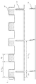
図6にパルス駆動電流11とQスイッチ素子印加電圧12とQスイッチパルス出力13のタイミング・チャートを示す。レーザダイオードの電流パルス時間幅Wは、レーザ媒質固有の上準位蛍光寿命に近い値とすることにより、最大限のレーザ光のQスイッチパルスエネルギーが得られるため固定としている。また、Qスイッチ制御を行うポッケルス素子に印加する高圧をスイッチングするタイミングΔtは、レーザダイオードの電流パルスの終端付近に調整され固定されている。斜線部で示されるパルス電流値ILDとΔtの積がレーザ媒質に蓄積されるエネルギーに対応し、発振するQスイッチエネルギーが決定される。このため、パルス電流値ILDを調整することによりQスイッチエネルギー13が調節できる。
一方、レーザダイオードの発振波長は、レーザダイオードの半導体チップ温度によりシフトする。一般的なレーザダイオードでは、レーザダイオードのケース温度に対して、約0.3nm/℃のシフト量で変化することが知られている。また、一般的に市販されているレーザダイオードの発振波長は、ケース温度を同一温度に設定しても生産上の歩留まりにより約±3nmの個体差がある。
レーザ媒質側の励起光の吸収特性に関しては、通常ある吸収ピークの中心波長に対して数nmの範囲の波長しか有効に吸収されないという特性を有している。例えば、Nd:YLF結晶では、一般に多用される波長798nmの吸収ピークに対して半値全幅は2nm程度である。このため、一般的にはケース温度を調節してレーザダイオードの発振波長をレーザ媒質の吸収ピークに一致させることにより、効率的な励起を行ってレーザ出力を得ている。図5の構成図にもレーザダイオードのケース温度TLDを検知しながら設定値に一定に保つための温度制御する機能7が含まれている。
しかし、チップとケースとの間には熱抵抗があるため、チップ温度と制御系の検出温度であるケース温度との間には差が生じ、あるレーザダイオードの電流に対する抵抗負荷による熱発生量に対してケース温度を一定に保つ制御を行っても、熱源であるチップ温度は多少変化してしまう。また時間的にも過渡特性がある。このため、温度調整によるレーザダイオード発振波長の最適化は、特定の熱発生条件、つまりレーザダイオードの特定のパルス駆動電流値及び繰り返し周波数の駆動条件下にて行われる。特にパルス励起のレーザ発振器では、レーザダイオード駆動パルス電流の繰り返しを単発から数10、ないし数100Hzまで変化させるため、熱発生量は数10から数100倍変化することになる。レーザダイオードの駆動パルスの電流値と周波数の双方を調節してレーザパルス出力レベルとレーザパルス繰り返し周波数を制御する従来技術では、上記の理由からある繰り返し条件では波長が最適であって効果的にレーザ出力が得られるが、他の繰り返し条件では波長が逸脱する方向となり、結果としてレーザ出力は低下していた。
この課題に対応するために、特性に個体差のあるレーザダイオード個々に対して、しかも多岐にわたる駆動パルス電流条件に合わせて波長一定となる温度条件を測定して記憶しておき、パルス電流値と繰り返しの条件が与えられたときに、記憶された温度条件にレーザダイオードを温度制御する方法も考えられるが、工業用レーザ発振器を生産する観点からは現実的ではない。
FIG. 6 shows a timing chart of the
On the other hand, the oscillation wavelength of the laser diode is shifted by the semiconductor chip temperature of the laser diode. It is known that a general laser diode changes with a shift amount of about 0.3 nm / ° C. with respect to the case temperature of the laser diode. Further, the oscillation wavelength of a commercially available laser diode has an individual difference of about ± 3 nm depending on production yield even when the case temperature is set to the same temperature.
The absorption characteristic of the excitation light on the laser medium side has a characteristic that only a wavelength in the range of several nm is effectively absorbed with respect to the central wavelength of a certain absorption peak. For example, in an Nd: YLF crystal, the full width at half maximum is about 2 nm with respect to an absorption peak with a wavelength of 798 nm that is generally used. For this reason, in general, the case temperature is adjusted to make the oscillation wavelength of the laser diode coincide with the absorption peak of the laser medium, whereby efficient excitation is performed to obtain a laser output. The configuration diagram of FIG. 5 also includes a
However, since there is a thermal resistance between the chip and the case, there is a difference between the chip temperature and the case temperature, which is the detection temperature of the control system, and the amount of heat generated by a resistive load with respect to the current of a certain laser diode. On the other hand, even if control is performed to keep the case temperature constant, the chip temperature as a heat source changes somewhat. There is also a transient characteristic in time. For this reason, optimization of the laser diode oscillation wavelength by temperature adjustment is performed under specific heat generation conditions, that is, under specific pulse drive current value and repetition frequency drive conditions of the laser diode. In particular, in a pulse excitation laser oscillator, since the repetition of the laser diode driving pulse current is changed from a single shot to several tens to several hundreds Hz, the amount of heat generation changes from several tens to several hundreds times. In the conventional technology that controls the laser pulse output level and the laser pulse repetition frequency by adjusting both the current value and the frequency of the drive pulse of the laser diode, the wavelength is optimal under the repetition condition for the above reason, and the laser is effectively used. Although an output is obtained, the wavelength is deviated in other repetition conditions, and as a result, the laser output is reduced.
In order to cope with this problem, for each laser diode having individual differences in characteristics, temperature conditions where the wavelength is constant according to various driving pulse current conditions are measured and stored, and the pulse current value and A method of controlling the temperature of the laser diode to the stored temperature condition when a repetition condition is given can be considered, but it is not practical from the viewpoint of producing an industrial laser oscillator.
本発明は、上記のような従来のパルス駆動レーザダイオード励起Qスイッチ固体レーザ発振器の制御方法のもつ問題点に鑑みてなされたものであって、その目的とするところは、パルス駆動のレーザダイオードを用いたQスイッチ発振の固体レーザ発振器において、レーザダイオードの発振波長の変動を抑制する手段と手法を備えることによって、Qスイッチパルスの繰り返し周波数と出力エネルギーを独立に指定できる制御性のよいレーザ光源を提供することにある。 The present invention has been made in view of the problems of the control method of the conventional pulse-driven laser diode-pumped Q-switched solid-state laser oscillator as described above. The object of the present invention is to provide a pulse-driven laser diode. The Q-switch oscillation solid-state laser oscillator used has a controllable laser light source that can specify the repetition frequency and output energy of the Q-switch pulse independently by providing means and method for suppressing fluctuations in the oscillation wavelength of the laser diode. It is to provide.
上記の課題を解決するために、本発明のパルス駆動レーザダイオード励起Qスイッチ固体レーザ発振器は、パルス駆動のレーザダイオードをレーザ媒質の光励起素子に用いたQスイッチ発振の固体レーザ発振器であって、レーザダイオードの複数からなるパルス駆動条件を所定の条件に固定してレーザダイオードを駆動するレーザダイオード駆動手段と、レーザダイオードを前記固定したパルス駆動条件で最適な温度に制御するレーザダイオード温度制御手段と、Qスイッチ発振を生起するQスイッチ素子の駆動タイミングを可変するQスイッチ素子制御手段と、を備え、前記Qスイッチ素子制御手段は、固体レーザ発振器の発振Qスイッチパルスの出力エネルギーと周期とを独立に可変制御することを特徴とする。
固定する複数のレーザダイオードのパルス駆動条件は、パルスの電流値とパルス時間幅とパルス繰り返し周期であることが好ましい。
また、一定に制御するレーザダイオードの最適な温度は、レーザダイオードの発振波長が、レーザ媒質の吸収ピーク波長となる温度であることが好ましい。
発振Qスイッチパルスの出力エネルギーの可変制御は、Qスイッチ素子の駆動タイミングをレーザダイオード駆動パルスのパルス時間幅内で可変することによって行うように構成することができる。
また、発振Qスイッチパルス周期の可変制御は、Qスイッチ素子の駆動周期をレーザダイオード駆動パルスのパルス周期のn倍(nは正の整数)で離散的に可変することによって行ってもよい。
レーザダイオードの駆動パルス時間幅は、レーザ媒質の上準位蛍光寿命であることが好ましい。
前記Qスイッチ素子の駆動周期の離散的な可変は、レーザ光の繰り返し周波数の種類に対応して予め複数組設定された前記レーザダイオード駆動パルスの繰り返し周波数と前記Qスイッチ素子の繰り返し周波数との組み合わせから前記nの大きさに応じて1の組み合わせを選択し、選択したレーザダイオード駆動パルスの繰り返し周波数を外部から前記レーザダイオード駆動手段及び前記Qスイッチ素子制御手段に入力し、選択したQスイッチ素子の繰り返し周波数を外部から前記Qスイッチ素子制御手段に入力することにより、前記レーザダイオード駆動パルスのパルス周期及び前記Qスイッチ素子の駆動周期を設定することによって行うように構成することができる。
In order to solve the above problems, a pulse-driven laser diode-pumped Q-switched solid-state laser oscillator of the present invention is a Q-switched solid-state laser oscillator using a pulse-driven laser diode as an optical pumping element of a laser medium, A laser diode driving means for driving a laser diode by fixing a plurality of diode pulse driving conditions to a predetermined condition; a laser diode temperature control means for controlling the laser diode to an optimum temperature under the fixed pulse driving conditions; and a Q-switch element control means for varying the driving timing of the Q switch element to rise to Q-switch oscillation, the Q-switch element control means, independently and output energy and the period of oscillation Q-switched pulsed solid-state laser oscillator It is characterized by variable control.
The pulse driving conditions of the plurality of laser diodes to be fixed are preferably a pulse current value, a pulse time width, and a pulse repetition period.
The optimum temperature of the laser diode is controlled to be constant, the oscillation wavelength of the laser diode is preferably a temperature at which the absorption peak wavelength of the laser medium.
Oscillation variable control of the Q-switched pulse output energy can be configured to perform by varying the driving timing of the Q switch element in the laser diode within the pulse duration of the drive pulse.
Further, the variable control of the oscillation Q-switched pulse period, n times the pulse period of the driving cycle laser diode driving pulses of the Q-switch element (n is a positive integer) I row by discretely variably.
The drive pulse time width of the laser diode is preferably the upper level fluorescence lifetime of the laser medium.
The discrete change of the driving period of the Q switch element is a combination of a repetition frequency of the laser diode driving pulse set in advance corresponding to the type of repetition frequency of the laser light and a repetition frequency of the Q switch element. 1 is selected according to the magnitude of n, and the repetition frequency of the selected laser diode drive pulse is externally input to the laser diode drive means and the Q switch element control means, and the selected Q switch element By inputting a repetition frequency from the outside to the Q switch element control means, the pulse period of the laser diode drive pulse and the drive period of the Q switch element can be set.
また、本発明のパルス駆動レーザダイオード励起Qスイッチ固体レーザ発振器の発振制御方法は、パルス駆動のレーザダイオードをレーザ媒質の光励起素子に用いたQスイッチ発振の固体レーザ発振器において、レーザダイオードの複数からなるパルス駆動条件を所定の条件に固定してレーザダイオードを駆動し、レーザダイオードを前記固定したパルス駆動条件で最適な温度に制御し、Qスイッチ発振を生起するQスイッチ素子の駆動タイミングを可変して、固体レーザ発振器の発振Qスイッチパルスの出力エネルギーと周期とを独立に可変制御することを特徴とする。
固定する複数のレーザダイオードのパルス駆動条件は、パルスの電流値とパルス時間幅とパルス繰り返し周期であることが好ましい。
また、一定に制御するレーザダイオードの最適な温度は、レーザダイオードの発振波長が、レーザ媒質の吸収ピーク波長となる温度であることが好ましい。
発振Qスイッチパルスの出力エネルギーの可変制御は、Qスイッチ素子の駆動タイミングをレーザダイオード駆動パルスのパルス時間幅内で可変することによって行うように構成することができる。
また、発振Qスイッチパルス周期の可変制御は、Qスイッチ素子の駆動周期をレーザダイオード駆動パルスのパルス周期のn倍(nは正の整数)で離散的に可変することによって行ってもよい。
レーザダイオードの駆動パルス時間幅は、レーザ媒質の上準位蛍光寿命であることが好ましい。
前記Qスイッチ素子の駆動周期の離散的な可変は、レーザ光の繰り返し周波数の種類に対応して予め複数組設定された前記レーザダイオード駆動パルスの繰り返し周波数と前記Qスイッチ素子の繰り返し周波数との組み合わせから前記nの大きさに応じて1の組み合わせを選択し、選択したレーザダイオード駆動パルスの繰り返し周波数を外部から前記レーザダイオード駆動手段及び前記Qスイッチ素子制御手段に入力し、選択したQスイッチ素子の繰り返し周波数を外部から前記Qスイッチ素子制御手段に入力することにより、前記レーザダイオード駆動パルスのパルス周期及び前記Qスイッチ素子の駆動周期を設定することによって行うように構成することができる。
Also, the oscillation control method for a pulse-driven laser diode-pumped Q-switched solid-state laser oscillator of the present invention comprises a plurality of laser diodes in a Q-switched solid-state laser oscillator using a pulse-driven laser diode as an optical pumping element of a laser medium The laser diode is driven with the pulse drive condition fixed to a predetermined condition, the laser diode is controlled to an optimum temperature under the fixed pulse drive condition, and the drive timing of the Q switch element that causes Q switch oscillation is varied. , characterized by variably controlling the output energy and the period of oscillation Q-switched pulsed solid state laser oscillator independently.
The pulse driving conditions of the plurality of laser diodes to be fixed are preferably a pulse current value, a pulse time width, and a pulse repetition period.
The optimum temperature of the laser diode is controlled to be constant, the oscillation wavelength of the laser diode is preferably a temperature at which the absorption peak wavelength of the laser medium.
Oscillation variable control of the Q-switched pulse output energy can be configured to perform by varying the driving timing of the Q switch element in the laser diode within the pulse duration of the drive pulse.
Further, the variable control of the oscillation Q-switched pulse period, n times the pulse period of the driving cycle laser diode driving pulses of the Q-switch element (n is a positive integer) I row by discretely variably.
The drive pulse time width of the laser diode is preferably the upper level fluorescence lifetime of the laser medium.
The discrete change of the driving period of the Q switch element is a combination of a repetition frequency of the laser diode driving pulse set in advance corresponding to the type of repetition frequency of the laser light and a repetition frequency of the Q switch element. 1 is selected according to the magnitude of n, and the repetition frequency of the selected laser diode drive pulse is externally input to the laser diode drive means and the Q switch element control means, and the selected Q switch element By inputting a repetition frequency from the outside to the Q switch element control means, the pulse period of the laser diode drive pulse and the drive period of the Q switch element can be set.
本発明の効果として第1の効果は、パルス駆動のレーザダイオードを用いたQスイッチ発振の固体レーザ発振器において、パルス繰り返し周波数を調整しても出力エネルギーは不変であるため、繰り返し周波数と出力エネルギーを独立に指定できる制御性のよいレーザ光源を提供する。
第2の効果は、レーザダイオードの駆動条件を半固定状態にし、レーザ媒質を最適な波長で励起することにより、一定の励起分布に対して共振器アライメントを最適状態に維持できるため、励起状態の変化による不安定要素を抑制し、レーザ光ビーム横モードの強度分布、出力エネルギーの安定性向上につながることである。
第3の効果は、レーザ発振器の制御性が向上することにより、加工装置の外部光学系に出力調整の減衰装置や、安定状態まで待機するための外部シャッタを用いずに加工出力の精密制御が可能となり加工装置のコンパクト化につながることである。
The first effect of the present invention is that, in a Q-switch oscillation solid-state laser oscillator using a pulse-driven laser diode, the output energy does not change even if the pulse repetition frequency is adjusted. Provided is a laser light source with high controllability that can be specified independently.
The second effect is that the resonator alignment can be maintained in an optimum state with respect to a fixed excitation distribution by setting the laser diode driving condition to a semi-fixed state and exciting the laser medium at an optimum wavelength. Instability factors due to changes are suppressed, leading to improved stability of the intensity distribution of the laser beam transverse mode and output energy.
The third effect is that the controllability of the laser oscillator is improved, so that the machining output can be precisely controlled without using an output adjusting attenuation device or an external shutter for waiting for a stable state in the external optical system of the machining device. It becomes possible and leads to downsizing of the processing equipment.
本発明の実施の形態について図面を参照して説明する。 Embodiments of the present invention will be described with reference to the drawings.
図1は本発明のパルス駆動レーザダイオード励起Qスイッチ固体レーザ発振器の構成を示すブロック図である。
レーザ発振器は、レーザヘッド部10とレーザダイオード制御ユニット20とQスイッチ素子制御ユニット30で構成される。
レーザヘッド部10は、レーザ共振器1、固体レーザ媒質2、励起用レーザダイオード3とQスイッチ動作をするためのポッケルス素子4からなる。
レーザダイオード制御ユニット20は、レーザダイオードを駆動するためのパルス電流源5と、励起用レーザダイオードを温度制御する温度制御部7と、一定のパルス繰り返し周波数fLDを発振する発振器9を含む。
Qスイッチ素子制御ユニット30は、ポッケルス素子を駆動するための高電圧スイッチング電源6とポッケルス素子に印加される高電圧パルスをレーザダイオード駆動パルスに同期をとるための同期部8とで構成される。
FIG. 1 is a block diagram showing the configuration of a pulse-driven laser diode-pumped Q-switched solid-state laser oscillator according to the present invention.
The laser oscillator includes a
The
The laser
The Q switch
レーザダイオード制御ユニット20では、発振器9の発振する繰り返し周波数一定fLDの信号を受けて、パルス電流源5は、レーザダイオードのパルス駆動条件である繰り返し周波数fLDに加えて、電流値ILD及び電流パルス幅Wも一定値に固定して出力する。これらの積分値はレーザダイオードに与えられる平均電力量に相当する。この積分値を一定値に固定することは、すなわちレーザダイオードの平均的な熱発生量を一定に保つことになる。
温度制御部7は、レーザダイオードのパルス駆動条件である電流値ILD及び電流パルス幅W及び繰り返し周波数fLDが一定の条件において、個体差をもつレーザダイオードのケース温度TLDをレーザダイオードの発振波長が最適波長になるように合わせ固定する。すなわち、ダイオードチップ内の熱発生によるケース温度の変化を検知しながら、例えばペルチェ素子のような電子冷却素子により温度制御を行い、レーザダイオードの発振波長がレーザ媒質の吸収ピーク波長に一致するようにケース温度を制御する。
ここで付け加えると、レーザダイオードの駆動条件を固定している期間は、一連のレーザ加工処理を行う短期的な時間の範囲であり、例えばレーザダイオードの消耗による発生光量を補正するための電流値増加の機能をパルス電流源5は備えていることが望ましい。
Qスイッチ素子制御ユニット30では、同期部8に外部からレーザダイオード駆動パルス立ち上がりからのQスイッチ遅れ時間Δtと、Qスイッチの繰り返し周波数fPC とが入力される。また、発振器9からレーザダイオード駆動パルス繰り返しタイミング信号fLDが入力される。これにより、同期部8は、レーザダイオード駆動パルス繰り返しタイミング信号fLDに同期したQスイッチ駆動信号12を生成する。
高電圧スイッチング電源6は、生成された信号を高電圧信号HVに変換してポッケルス素子4に印加する。
In the laser
The
In addition, the period during which the laser diode driving conditions are fixed is a short-term time range in which a series of laser processing is performed, for example, an increase in current value for correcting the amount of light generated due to laser diode consumption. It is desirable that the pulse
In Q-switching
The high voltage switching
図2に本発明のレーザ発振器構成によるQスイッチ動作のタイミング・チャートを示す。まず、外部から与えられるレーザダイオード開始信号STにより、発振器9によってレーザダイオードのタイミング信号fLDが生成され、レーザダイオードの駆動は開始される。レーザダイオードの駆動パルス電流11は、期待する最大のQスイッチパルスエネルギーが得られる電流値ILD及び電流パルス幅Wに設定されている。電流パルス幅Wは、レーザ媒質固有の上準位蛍光寿命に近い値とする。レーザダイオードの繰り返し周波数fLDも、レーザダイオードの性能保証範囲内で、かつ固体レーザ出力をレーザ加工等に用いる場合の加工条件に必要な最大の値に設定する。
このようにレーザダイオードの駆動条件が決定されると、レーザダイオードの熱発生量が決まり、レーザダイオードのケース温度をTLDに調節することにより、発光部の半導体チップ温度TCHIPが最適温度に定まり、レーザダイオードの励起発振波長はレーザ媒質の吸収ピーク波長に一致させて固定させることができる。温度制御部7は、ダイオードチップ内の熱発生によるケース温度の変化を検知しながら、ケースを温度制御し、レーザダイオードの発振波長がレーザ媒質の吸収ピーク波長に一致するケース温度TLDに到達した時点で安定し、スタンバイ状態となる。
次に、外部から同期部8にQスイッチ遅れタイミング時間ΔtとQスイッチの繰り返し信号fPCが入力され、これにより、レーザダイオードのタイミング信号fLDに同期した繰り返し信号fPCのQスイッチ素子駆動信号12が生成され、高電圧信号HVに変換されてポッケルス素子4に印加されることによりQスイッチパルスレーザ光13の発振が行われる。
FIG. 2 shows a timing chart of the Q switch operation according to the laser oscillator configuration of the present invention. First, a laser diode timing signal f LD is generated by the oscillator 9 in response to a laser diode start signal ST given from the outside, and the laser diode is started to be driven. The drive pulse current 11 of the laser diode is set to a current value I LD and a current pulse width W at which the expected maximum Q switch pulse energy can be obtained. The current pulse width W is set to a value close to the upper level fluorescence lifetime specific to the laser medium. The repetition frequency f LD of the laser diode is also set to the maximum value necessary for the processing conditions when the solid laser output is used for laser processing or the like within the performance guarantee range of the laser diode.
When the drive condition of the laser diode is determined such, determines the heat generation amount of the laser diode by adjusting a case temperature of the laser diode T LD, a semiconductor chip temperature T CHIP emitting portion Sadamari the optimum temperature The excitation oscillation wavelength of the laser diode can be fixed in accordance with the absorption peak wavelength of the laser medium. The
Next, the Q switch delay timing time Δt and the Q switch repetition signal f PC are input to the synchronization unit 8 from the outside, whereby the Q switch element drive signal of the repetition signal f PC synchronized with the timing signal f LD of the laser diode. 12 is generated, converted into a high voltage signal HV, and applied to the Pockels element 4 to oscillate the Q switch
レーザ発振の繰り返し周波数を変化させるには、Qスイッチ繰り返し信号fPCを変更する。つまり、レーザダイオードのパルス電流の繰り返し周波数fLDに対して1/n分周の周波数条件をもつfPC(fPC=fLD/n:nは整数)を与えると、この新たなfPCの繰り返し周波数のレーザ光が発生する。
レーザ光のパルスエネルギーを変化させるには、Qスイッチ遅れ時間Δtを変更することにより制御することができる。つまり、Δtをレーザダイオードの電流パルス幅Wとほぼ一致させると最大Qスイッチパルスエネルギーが得られ、Δtを減少してQスイッチをかけるタイミングを調整すると、Qスイッチエネルギーとして抽出されるレーザ媒質の蓄積エネルギーが減少し、レーザ光の出力エネルギーが調整できる。
本発明で創案した機能は、上記に示した一連の制御が可能なレーザダイオード制御ユニット20のレーザダイオード駆動制御機能、及びポッケルス素子を駆動するためのQスイッチ素子制御ユニット30のQスイッチタイミング制御機能を複合したものである。
To vary the repetition frequency of the laser oscillator changes the Q-switch repetition signal f PC. That is, if f PC having a frequency condition of 1 / n division with respect to the repetition frequency f LD of the pulse current of the laser diode is given (f PC = f LD / n: n is an integer), this new f PC Laser light having a repetition frequency is generated.
The pulse energy of the laser beam can be changed by changing the Q switch delay time Δt. In other words, the maximum Q switch pulse energy can be obtained by making Δt substantially coincide with the current pulse width W of the laser diode, and if the timing for applying the Q switch by adjusting Δt is adjusted, the accumulation of the laser medium extracted as the Q switch energy is obtained. The energy is reduced, and the output energy of the laser beam can be adjusted.
The functions created by the present invention include the laser diode drive control function of the laser
次に、温度制御部7の動作を説明する。
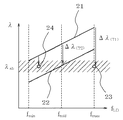
図3は、固定レーザ発振器組立前に予め測定することができるレーザダイオードのパルス電流の繰り返し周波数fLDに対する発振波長λの変化の傾向を示す。
従来のケース温度を調節してレーザダイオード発振波長を最適化する方式は、前述の如く特定の熱発生条件、つまりレーザダイオードの特定のパルス駆動電流値及び繰り返し周波数の駆動条件下にて行われている。この温度制御方法について図3を用いて説明すると、特性曲線21は、レーザダイオードの室温等の基準となるケース温度におけるλ−fLD特性である。従来の温度制御機能は、特定のパルス繰り返し周波数fmidにおいて、レーザダイオードの発振波長が、レーザ媒質の吸収ピーク波長λabに一致するようにレーザダイオードのケース温度をT2に設定し、λ−fLDの特性を21から22に移行させて一定値に制御する方法である。レーザダイオードのケース温度をT2に設定し一定値に制御しても、熱源である半導体チップ部の熱発生量が繰り返しの変化によって増減すると、ケースと半導体チップには熱抵抗があるためチップ温度TCHIPは変化する。チップ温度TCHIPの変化は、レーザダイオードの発振波長λの変化を生じさせる。特にレーザダイオードをパルス駆動した場合は、使用する繰り返し周波数の範囲が広いほど、熱発生量の増減範囲は大きくなり、レーザ媒質の吸収ピークの幅(斜線部)よりもっと広い範囲の波長変化が生じ、レーザ出力の低下が起こる。
これに対して、本発明の方式では、先述のようにレーザダイオードの駆動繰り返し周波数fLDは、レーザダイオードの性能保証範囲内であり、かつ例えば発振器出力をレーザ加工条件等に必要な最大の周波数fMAX(特性23)に固定している。この一定条件下で、温度制御部7は、レーザダイオードのケース温度TLDをT1に制御してレーザダイオードの発振波長をレーザ媒質の吸収ピーク波長λabに安定させる。
本方式では、QスイッチのタイミングΔtを変化させてレーザ出力を制御しても、またQスイッチ繰り返し周波数fpcを変化させても、fLDはfMAXのままで変化しないため波長の逸脱がない。
Next, the operation of the
FIG. 3 shows the tendency of the change in the oscillation wavelength λ with respect to the repetition frequency f LD of the pulse current of the laser diode, which can be measured in advance before the assembly of the fixed laser oscillator.
The conventional method of adjusting the case temperature and optimizing the laser diode oscillation wavelength is performed under specific heat generation conditions, that is, under the specific pulse drive current value and repetition frequency drive condition of the laser diode as described above. Yes. This temperature control method will be described with reference to FIG. 3. A
On the other hand, in the method of the present invention, as described above, the laser diode drive repetition frequency f LD is within the performance guarantee range of the laser diode, and the maximum output frequency required for the laser processing conditions, for example, is required. It is fixed to f MAX (characteristic 23). Under this constant condition, the
In this method, even if the laser output is controlled by changing the timing Δt of the Q switch or the Q switch repetition frequency f pc is changed, f LD remains f MAX and does not change, so there is no wavelength deviation. .
以上に構成と動作について述べた本発明のレーザ発振器の出力制御と発振繰り返し制御の特長を説明する。
Qスイッチ遅れ時間Δtとパルス電流値ILDで決まる斜線部が、Qスイッチを行う時点のレーザ媒質の蓄積エネルギーに相当し、レーザ発振器出力光のパルスエネルギー13と相関性がある。このため、予めQスイッチ遅れ時間Δtと出力エネルギーの特性を予め測定してテーブル化しておくことにより、このテーブルによりレーザ発振器出力の制御が可能である。
この出力制御方式を従来の固体レーザ発振器出力制御をレーザダイオードの電流値による制御によって行う方式と比較すると、従来方式では励起波長シフトが必然的に課題となって生じ、これによってレーザ媒質の吸収エネルギーの変化を引き起こし、レーザ媒質に励起光が侵入したときの吸収の傾向、つまり励起分布の変化として現れ、レーザ光ビーム横モードの強度分布のずれ、揺らぎによる不安定性につながっているが、本発明のように励起状態固定の場合にはこの効果が抑制される。
The features of the output control and oscillation repetition control of the laser oscillator of the present invention described above for the configuration and operation will be described.
Shaded area determined by the Q-switch delay time Δt and the pulse current value I LD is equivalent to the stored energy of the laser medium at the time of performing Q-switch is a
When this output control method is compared with the conventional method in which the solid-state laser oscillator output control is performed by controlling the current value of the laser diode, the pump wavelength shift inevitably becomes a problem in the conventional method. The change in absorption when the excitation light enters the laser medium, that is, a change in the excitation distribution, appears as a change in the intensity distribution of the laser light beam transverse mode, leading to instability due to fluctuations. Thus, this effect is suppressed when the excited state is fixed.
また、レーザ発振繰り返しを変化させる場合にはQスイッチ繰り返し信号fPCをレーザダイオードのパルス電流の繰り返し周波数fLDに対して分周された周波数条件を持ったfPC(fPC=fLD/n:nは整数)を与えることにより低繰り返しのレーザ光が発生する。図2ではn=2の状態を示している。
このとき、レーザ発振を間引いていることと同じであり、繰り返し周波数を変化させても出力レーザパルスエネルギーは変化しない。また、繰り返し周波数を変化させても励起されるレーザ媒質の熱的状態は変化せず一定であるため、共振器アライメントを常に最適調整の状態に保ことができる。これは従来技術のようにパルス電流の繰り返し周波数fLDによる励起分布や熱的歪みの変化が引き起こす共振器アライメントのずれがないため出力安定度の向上につながる。
ただし、この方式では繰り返し周波数を同じ変化量で細かく調整をすることはできないが、通常のレーザ加工では数種もしくはシングルショットなどの切り換えで十分であることが多く、最大繰り返しであるfMAXを励起用レーザダイオードの繰り返し周波数fLDに選定することで実用上の弊害は少ない。
When the laser oscillation repetition is changed, f PC (f PC = f LD / n) having a frequency condition obtained by dividing the Q switch repetition signal f PC with respect to the repetition frequency f LD of the pulse current of the laser diode. : N is an integer), a low repetition laser beam is generated. FIG. 2 shows a state where n = 2.
At this time, it is the same as thinning out the laser oscillation, and the output laser pulse energy does not change even if the repetition frequency is changed. Further, even if the repetition frequency is changed, the thermal state of the laser medium to be excited does not change and is constant, so that the resonator alignment can always be kept in the optimal adjustment state. This leads to an improvement in output stability because there is no deviation in resonator alignment caused by a change in excitation distribution and thermal distortion due to the repetition frequency f LD of the pulse current as in the prior art.
However, with this method, the repetition frequency cannot be finely adjusted with the same amount of change, but in normal laser processing, switching between several types or single shots is often sufficient, and the maximum repetition f MAX is excited. By selecting the repetition frequency f LD of the laser diode for use, there are few practical problems.
以上の説明のように、本発明のレーザ発振器は以下の効果を奏す。
第1の効果は、パルス駆動のレーザダイオードを用いたQスイッチ発振の固体レーザ発振器において、パルス繰り返し周波数を調整しても出力エネルギーは不変であるため、繰り返し周波数と出力エネルギーを独立に指定できる制御性のよいレーザ光源を提供する。
第2の効果は、レーザダイオードの駆動条件を固定しレーザ媒質を最適な波長で励起することにより、一定の励起分布に対して共振器アライメントを最適状態に維持できるため、励起による不安定要素を抑制しレーザ光ビーム横モードの強度分布、出力エネルギーの安定性向上につながることである。
第3の効果は、レーザ発振器の制御性が向上することにより、加工装置の外部光学系に出力調整の減衰装置や、安定状態まで待機するための外部シャッタを用いずに加工出力の精密制御が可能となり加工装置のコンパクト化につながることである。
As described above, the laser oscillator of the present invention has the following effects.
The first effect is that, in a Q-switch oscillation solid-state laser oscillator using a pulse-driven laser diode, the output energy remains unchanged even if the pulse repetition frequency is adjusted, so that the repetition frequency and output energy can be specified independently. A laser light source with good characteristics is provided.
The second effect is that by fixing the laser diode driving conditions and exciting the laser medium at the optimum wavelength, the resonator alignment can be maintained in an optimum state with respect to a constant excitation distribution. This is to suppress the laser light beam transverse mode intensity distribution and improve the stability of the output energy.
The third effect is that the controllability of the laser oscillator is improved, so that the machining output can be precisely controlled without using an output adjusting attenuation device or an external shutter for waiting for a stable state in the external optical system of the machining device. It becomes possible and leads to downsizing of the processing equipment.
なお、一般的にQスイッチの方式として、高電圧を印加したときにレーザ発振するオンスイッチ方式と、高電圧を印加しレーザ発振停止した後に高電圧を切ったとき発振するオフスイッチ方式があるがいずれの方式でもよい。また、電気光学効果型の素子のみならず、必要に応じて音響効果型の素子を用いてもよい。 In general, as a Q switch system, there are an on-switch system that oscillates when a high voltage is applied, and an off-switch system that oscillates when the high voltage is turned off after applying a high voltage to stop laser oscillation. Either method may be used. In addition to the electro-optic effect element, an acoustic effect element may be used as necessary.
次に、本発明の第2の実施例について図4を参照して詳細に説明する。
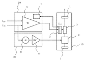
図4は、図1のレーザ発振器の構成のうち、レーザヘッド部10を除くレーザダイオード制御ユニット20とQスイッチ素子制御ユニット30を示している。
上述の第1の実施例ではレーザダイオードの繰り返し周波数fLDを固定するとしていたが、例えば高繰り返し周波数と低繰り返し周波数でのみしか使用しない場合には、低繰り返し時に発振に寄与しないレーザダイオードの発光が多いため、レーザダイオードの寿命への影響が懸念される面もある。図4に示す実施例はこれに対応するため機能を拡張したものである。
レーザダイオードの繰り返し周波数fLDを高繰り返し時には、その最大値をf1LDに選定し、低繰り返し時にはその最大値をf2LDに選定する。各々に対して最適励起波長となるレーザダイオードのケース温度T1LD、T2LDを測定しておき記憶する。これは図3に示す調整点23の他に調整点24を設けることである。この各繰り返し信号に対して、分周するQスイッチの繰り返し信号fPCがfPC=fLD/n(nは整数)の条件を満たし、各分周の割合nによって決まる複数のf1PC、f2PCを設けると高低の多種にわたるパルス繰り返しの選定が可能となる。
Next, a second embodiment of the present invention will be described in detail with reference to FIG.
FIG. 4 shows a laser
In the first embodiment described above, the repetition frequency f LD of the laser diode is fixed. For example, when only the high repetition frequency and the low repetition frequency are used, the light emission of the laser diode that does not contribute to oscillation at the low repetition frequency. In many cases, there is a concern about the influence on the life of the laser diode. The embodiment shown in FIG. 4 has an expanded function to cope with this.
When the repetition frequency f LD of the laser diode is high, the maximum value is selected as f1 LD , and when the repetition frequency is low, the maximum value is selected as f2 LD . The laser diode case temperatures T1 LD and T2 LD, which are optimum excitation wavelengths for each, are measured and stored. This is to provide an
外部から低繰り返しのf2PCを指定した場合には、レーザダイオード開始信号STと共にレーザダイオードの低繰り返し時の最大周波数の駆動信号f2LDがパルス電流源5に与えられ、レーザダイオードの設定温度T2LDが温度制御機能7に与えられてレーザダイオードの駆動は開始される。そしてレーザダイオードの波長は、図3の調整点24に安定化される。その後、パルスエネルギーを決定するQスイッチ遅れ時間ΔtとQスイッチの繰り返し信号f2PCが高電圧スイッチング電源6に与えられるとレーザ発振する。このとき、レーザダイオードの発振に寄与しない発光は、高繰り返し時の最大周波数の駆動信号f1LDで駆動したときよりも少ないため、レーザダイオードの消耗は少なくなる。
上記の例は調整点を2個とした場合であるが、加工条件に要求されるレーザ光の繰り返し周波数の種類に対応してfLD、fPC、TLDの複数の組み合わせを外部入力できるようにしておくことで、効率よく無駄な発光を減らしてレーザダイオードの駆動をすることも可能である。
When low repetition f2 PC is designated from the outside, the laser diode start signal ST and the maximum frequency drive signal f2 LD at the time of low repetition of the laser diode are given to the pulse
In the above example, the number of adjustment points is two, but a plurality of combinations of f LD , f PC , and T LD can be externally input corresponding to the type of repetition frequency of laser light required for processing conditions. In this way, it is possible to drive the laser diode while efficiently reducing wasteful light emission.
本第2の実施例は以下の効果を奏す。
第1の効果は、パルス駆動のレーザダイオードを用いたQスイッチ発振の固体レーザ発振器において、パルス繰り返し周波数を調整しても出力エネルギーは不変であるため、繰り返し周波数と出力エネルギーを独立に指定できる制御性のよいレーザ光源を提供する。
第2の効果は、レーザ発振器の制御性が向上することにより、加工装置の外部光学系に出力調整の減衰装置や、安定状態まで待機するための外部シャッタを用いずに加工出力の精密制御が可能となり加工装置のコンパクト化につながることである。
The second embodiment has the following effects.
The first effect is that, in a Q-switch oscillation solid-state laser oscillator using a pulse-driven laser diode, the output energy remains unchanged even if the pulse repetition frequency is adjusted, so that the repetition frequency and output energy can be specified independently. A laser light source with good characteristics is provided.
The second effect is that the controllability of the laser oscillator is improved, so that the machining output can be precisely controlled without using an output adjusting attenuation device or an external shutter for waiting for a stable state in the external optical system of the machining device. It becomes possible and leads to downsizing of the processing equipment.
1 レーザ共振器
2 レーザ媒質
3 レーザダイオード
4 ポッケルス素子
5 パルス電流源
6 高電圧スイッチング電源
7 温度制御機能
8 同期部
9 発振器
10 レーザヘッド部
11 レーザダイオードの駆動パルス電流
12 Qスイッチ素子駆動信号
13 パルスレーザ光
20 レーザダイオード制御ユニット
30 Qスイッチ素子制御ユニット
DESCRIPTION OF
Claims (14)
前記レーザダイオードの複数からなるパルス駆動条件を所定の条件に固定して前記レーザダイオードを駆動するレーザダイオード駆動手段と、
前記レーザダイオードを前記固定したパルス駆動条件で最適な温度に制御するレーザダイオード温度制御手段と、
前記Qスイッチ発振を生起するQスイッチ素子の駆動タイミングを可変するQスイッチ素子制御手段と、
を備え、
前記Qスイッチ素子制御手段は、前記固体レーザ発振器の発振Qスイッチパルスの出力エネルギーと周期とを独立に可変制御する、
ことを特徴とするパルス駆動レーザダイオード励起Qスイッチ固体レーザ発振器。 A Q-switched solid-state laser oscillator using a pulse-driven laser diode as an optical excitation element of a laser medium,
A laser diode driving means for driving the laser diode while fixing a plurality of pulse driving conditions of the laser diode to a predetermined condition;
Laser diode temperature control means for controlling the laser diode to an optimum temperature under the fixed pulse driving condition;
A Q-switch element control means for varying the driving timing of the Q switch element to rise to the Q-switch oscillation,
With
The Q-switch element control means variably controls the output energy and the period of oscillation Q-switched pulse of the solid-state laser oscillator independently,
A pulse-driven laser diode-pumped Q-switched solid-state laser oscillator characterized by the above.
パルスの電流値とパルス時間幅とパルス繰り返し周期である、
ことを特徴とする請求項1に記載のパルス駆動レーザダイオード励起Qスイッチ固体レーザ発振器。 The pulse driving conditions for the plurality of laser diodes to be fixed are:
The pulse current value, pulse duration, and pulse repetition period.
The pulse-driven laser diode-pumped Q-switched solid-state laser oscillator according to claim 1.
前記レーザダイオードの発振波長が、前記レーザ媒質の吸収ピーク波長となる温度である、
ことを特徴とする請求項1に記載のパルス駆動レーザダイオード励起Qスイッチ固体レーザ発振器。 The optimum temperature of the laser diode to be controlled constant is
The oscillation wavelength of the laser diode is a temperature at which the absorption peak wavelength of the laser medium is obtained.
The pulse-driven laser diode-pumped Q-switched solid-state laser oscillator according to claim 1.
前記Qスイッチ素子の駆動タイミングを前記レーザダイオード駆動パルスのパルス時間幅内で可変することによって行う、
ことを特徴とする請求項2に記載のパルス駆動レーザダイオード励起Qスイッチ固体レーザ発振器。 The variable control of the output energy of the oscillation Q switch pulse is as follows:
By varying the drive timing of the Q switch element within the pulse time width of the laser diode drive pulse,
The pulse-driven laser diode-pumped Q-switched solid-state laser oscillator according to claim 2.
前記Qスイッチ素子の駆動周期を前記レーザダイオード駆動パルスのパルス周期のn倍(nは正の整数)で離散的に可変することによって行う、
ことを特徴とする請求項2に記載のパルス駆動レーザダイオード励起Qスイッチ固体レーザ発振器。 The variable control of the oscillation Q switch pulse period is as follows:
The drive period of the Q switch element is discretely varied by n times the pulse period of the laser diode drive pulse (n is a positive integer).
The pulse-driven laser diode-pumped Q-switched solid-state laser oscillator according to claim 2.
前記レーザ媒質の上準位蛍光寿命である、
ことを特徴とする請求項2に記載のパルス駆動レーザダイオード励起Qスイッチ固体レーザ発振器。 The drive pulse time width of the laser diode is:
The upper level fluorescence lifetime of the laser medium,
The pulse-driven laser diode-pumped Q-switched solid-state laser oscillator according to claim 2.
レーザ光の繰り返し周波数の種類に対応して予め複数組設定された前記レーザダイオード駆動パルスの繰り返し周波数と前記Qスイッチ素子の繰り返し周波数との組み合わせから前記nの大きさに応じて1の組み合わせを選択し、選択したレーザダイオード駆動パルスの繰り返し周波数を外部から前記レーザダイオード駆動手段及び前記Qスイッチ素子制御手段に入力し、選択したQスイッチ素子の繰り返し周波数を外部から前記Qスイッチ素子制御手段に入力することにより、
前記レーザダイオード駆動パルスのパルス周期及び前記Qスイッチ素子の駆動周期を設定することによって行う、
ことを特徴とする請求項5に記載のパルス駆動レーザダイオード励起Qスイッチ固体レーザ発振器。 The discrete variable of the driving cycle of the Q switch element is
One combination is selected according to the size of n from the combination of the repetition frequency of the laser diode driving pulse and the repetition frequency of the Q switch element, which are set in advance corresponding to the type of repetition frequency of the laser light. Then, the repetition frequency of the selected laser diode drive pulse is inputted from the outside to the laser diode drive means and the Q switch element control means, and the repetition frequency of the selected Q switch element is inputted from the outside to the Q switch element control means. By
By setting a pulse period of the laser diode driving pulse and a driving period of the Q switch element;
The pulse-driven laser diode-pumped Q-switched solid-state laser oscillator according to claim 5.
前記レーザダイオードの複数からなるパルス駆動条件を所定の条件に固定して前記レーザダイオードを駆動し、
前記レーザダイオードを前記固定したパルス駆動条件で最適な温度に制御し、
前記Qスイッチ発振を生起するQスイッチ素子の駆動タイミングを可変して、
前記固体レーザ発振器の発振Qスイッチパルスの出力エネルギーと周期とを独立に可変制御する、
ことを特徴とするパルス駆動レーザダイオード励起Qスイッチ固体レーザ発振器の発振制御方法。 In a Q-switch oscillation solid-state laser oscillator using a pulse-driven laser diode as an optical pumping element of a laser medium,
Driving the laser diode by fixing a pulse driving condition consisting of a plurality of the laser diodes to a predetermined condition,
Controlling the laser diode to an optimum temperature under the fixed pulse driving conditions;
By varying the drive timing of the Q switch element that causes the Q switch oscillation,
Variably controlled independently an output energy and the period of oscillation Q-switched pulse of the solid-state laser oscillator,
An oscillation control method for a pulse-driven laser diode-pumped Q-switched solid-state laser oscillator characterized by the above.
パルスの電流値とパルス時間幅とパルス繰り返し周期である、
ことを特徴とする請求項8に記載のパルス駆動レーザダイオード励起Qスイッチ固体レーザ発振器の発振制御方法。 The pulse driving conditions for the plurality of laser diodes to be fixed are:
The pulse current value, pulse duration, and pulse repetition period.
The oscillation control method for a pulse-driven laser diode-pumped Q-switched solid-state laser oscillator according to claim 8.
前記レーザダイオードの発振波長が、前記レーザ媒質の吸収ピーク波長となる温度である、
ことを特徴とする請求項8に記載のパルス駆動レーザダイオード励起Qスイッチ固体レーザ発振器の発振制御方法。 The optimum temperature of the laser diode to be controlled constant is
The oscillation wavelength of the laser diode is a temperature at which the absorption peak wavelength of the laser medium is obtained.
The oscillation control method for a pulse-driven laser diode-pumped Q-switched solid-state laser oscillator according to claim 8.
前記Qスイッチ素子の駆動タイミングを前記レーザダイオード駆動パルスのパルス時間幅内で可変することによって行う、
ことを特徴とする請求項9に記載のパルス駆動レーザダイオード励起Qスイッチ固体レーザ発振器の発振制御方法。 The variable control of the output energy of the oscillation Q switch pulse is as follows:
By varying the drive timing of the Q switch element within the pulse time width of the laser diode drive pulse,
The oscillation control method for a pulse-driven laser diode-pumped Q-switched solid-state laser oscillator according to claim 9.
前記Qスイッチ素子の駆動周期を前記レーザダイオード駆動パルスのパルス周期のn倍(nは正の整数)で離散的に可変することによって行う、
ことを特徴とする請求項9に記載のパルス駆動レーザダイオード励起Qスイッチ固体レーザ発振器の発振制御方法。 The variable control of the oscillation Q switch pulse period is as follows:
The drive period of the Q switch element is discretely varied by n times the pulse period of the laser diode drive pulse (n is a positive integer).
The oscillation control method for a pulse-driven laser diode-pumped Q-switched solid-state laser oscillator according to claim 9.
前記レーザ媒質の上準位蛍光寿命である、
ことを特徴とする請求項9に記載のパルス駆動レーザダイオード励起Qスイッチ固体レーザ発振器の発振制御方法。 The drive pulse time width of the laser diode is:
The upper level fluorescence lifetime of the laser medium,
The oscillation control method for a pulse-driven laser diode-pumped Q-switched solid-state laser oscillator according to claim 9.
レーザ光の繰り返し周波数の種類に対応して予め複数組設定された前記レーザダイオード駆動パルスの繰り返し周波数と前記Qスイッチ素子の繰り返し周波数との組み合わせから前記nの大きさに応じて1の組み合わせを選択し、選択したレーザダイオード駆動パルスの繰り返し周波数を外部から前記レーザダイオード駆動手段及び前記Qスイッチ素子制御手段に入力し、選択したQスイッチ素子の繰り返し周波数を外部から前記Qスイッチ素子制御手段に入力することにより、
前記レーザダイオード駆動パルスのパルス周期及び前記Qスイッチ素子の駆動周期を設定することによって行う、
ことを特徴とする請求項12に記載のパルス駆動レーザダイオード励起Qスイッチ固体レーザ発振器の発振制御方法。 The discrete variable of the driving cycle of the Q switch element is
One combination is selected according to the size of n from the combination of the repetition frequency of the laser diode driving pulse and the repetition frequency of the Q switch element, which are set in advance corresponding to the type of repetition frequency of the laser light. Then, the repetition frequency of the selected laser diode drive pulse is inputted from the outside to the laser diode drive means and the Q switch element control means, and the repetition frequency of the selected Q switch element is inputted from the outside to the Q switch element control means. By
By setting a pulse period of the laser diode driving pulse and a driving period of the Q switch element;
13. The oscillation control method for a pulse-driven laser diode-pumped Q-switched solid-state laser oscillator according to claim 12.
Priority Applications (1)
| Application Number | Priority Date | Filing Date | Title |
|---|---|---|---|
| JP2003390785A JP4352871B2 (en) | 2003-11-20 | 2003-11-20 | Pulse-driven laser diode-pumped Q-switched solid-state laser oscillator and its oscillation control method |
Applications Claiming Priority (1)
| Application Number | Priority Date | Filing Date | Title |
|---|---|---|---|
| JP2003390785A JP4352871B2 (en) | 2003-11-20 | 2003-11-20 | Pulse-driven laser diode-pumped Q-switched solid-state laser oscillator and its oscillation control method |
Publications (2)
| Publication Number | Publication Date |
|---|---|
| JP2005158790A JP2005158790A (en) | 2005-06-16 |
| JP4352871B2 true JP4352871B2 (en) | 2009-10-28 |
Family
ID=34718047
Family Applications (1)
| Application Number | Title | Priority Date | Filing Date |
|---|---|---|---|
| JP2003390785A Expired - Lifetime JP4352871B2 (en) | 2003-11-20 | 2003-11-20 | Pulse-driven laser diode-pumped Q-switched solid-state laser oscillator and its oscillation control method |
Country Status (1)
| Country | Link |
|---|---|
| JP (1) | JP4352871B2 (en) |
Families Citing this family (5)
| Publication number | Priority date | Publication date | Assignee | Title |
|---|---|---|---|---|
| JP2007235063A (en) * | 2006-03-03 | 2007-09-13 | Tokyo Institute Of Technology | Q-switch laser and q-switch oscillation method |
| DE102006039398A1 (en) | 2006-08-22 | 2008-03-06 | Robert Bosch Gmbh | Method for operating a pump light source with a diode laser |
| JP2008235806A (en) * | 2007-03-23 | 2008-10-02 | Fujikura Ltd | Optical pulse generator |
| JP6033252B2 (en) * | 2014-03-27 | 2016-11-30 | 富士フイルム株式会社 | Laser apparatus and photoacoustic measuring apparatus including the same |
| JP7462220B2 (en) | 2020-05-08 | 2024-04-05 | パナソニックIpマネジメント株式会社 | Laser Oscillator |
Family Cites Families (8)
| Publication number | Priority date | Publication date | Assignee | Title |
|---|---|---|---|---|
| US5291505A (en) * | 1993-01-21 | 1994-03-01 | Hughes Aircraft Company | Active energy control for diode pumped laser systems using pulsewidth modulation |
| JP2500753B2 (en) * | 1993-05-13 | 1996-05-29 | 日本電気株式会社 | Small laser pointer |
| JPH08148740A (en) * | 1994-11-21 | 1996-06-07 | Miyachi Technos Corp | Solid-state laser masking device |
| JPH08222785A (en) * | 1995-02-14 | 1996-08-30 | Nippon Steel Corp | Solid state laser equipment |
| JP3487404B2 (en) * | 1997-10-31 | 2004-01-19 | 三菱電機株式会社 | Semiconductor laser pumped Q-switched solid-state laser device |
| JP3482945B2 (en) * | 2000-06-09 | 2004-01-06 | 日本電気株式会社 | Laser irradiation device for laser trimming device |
| JP2002359422A (en) * | 2001-05-30 | 2002-12-13 | Nec Corp | Q-switch laser controller and laser |
| JP2003198018A (en) * | 2001-12-28 | 2003-07-11 | Communication Research Laboratory | Light stimulated solid-state laser oscillator |
-
2003
- 2003-11-20 JP JP2003390785A patent/JP4352871B2/en not_active Expired - Lifetime
Also Published As
| Publication number | Publication date |
|---|---|
| JP2005158790A (en) | 2005-06-16 |
Similar Documents
| Publication | Publication Date | Title |
|---|---|---|
| US7656913B2 (en) | Fiber pulse laser apparatus and method of controlling the same | |
| US7599407B2 (en) | Laser control method, laser apparatus, laser treatment method used for the same, laser treatment apparatus | |
| US8599890B2 (en) | Systems and methods for laser pulse equalization | |
| EP1696522A2 (en) | Passively Q-switched laser with adjustable pulse repetition rate | |
| WO2000076037A1 (en) | Pulsed diode-pumped solid-state laser | |
| US6038240A (en) | Method and solid-state laser system for generating laser pulses with a variable pulse repetition frequency and constant beam characteristics | |
| US6931047B2 (en) | Laser light source | |
| US8964800B2 (en) | Microcrystal laser for generating laser pulses | |
| EP2736129A1 (en) | High-power pulsed light generator | |
| JP2005539365A (en) | Q-switch method for pulse train generation | |
| JP2009130143A (en) | Laser oscillation apparatus and method of controlling the same | |
| JP6562464B2 (en) | Passive Q-switched laser device | |
| JP4352871B2 (en) | Pulse-driven laser diode-pumped Q-switched solid-state laser oscillator and its oscillation control method | |
| JP2010502007A (en) | Driving method of pump light source provided with diode laser | |
| JPH1126858A (en) | Method for controlling q switch oscillation solid laser device and q switch oscillation solid laser device | |
| JP2001127366A (en) | Solid-state laser device, method for controlling output thereof and power supply device for solid-state laser | |
| JP5439836B2 (en) | Solid state laser equipment | |
| JP2002359422A (en) | Q-switch laser controller and laser | |
| JP2003347636A (en) | Q-switched laser apparatus and method for controlling q-switching | |
| JP2017103490A (en) | Solid-state pulse laser device | |
| JP2000223765A (en) | Semiconductor exciting solid state laser oscillating equipment | |
| JPH11135870A (en) | Solid-state laser device for oscillating semiconductor-laser exciting q switch | |
| JPH10321933A (en) | Semiconductor pumping solid-state laser | |
| WO2020179834A1 (en) | Control device and control method for fiber laser | |
| EP0904615A1 (en) | Pulsed laser with passive stabilization |
Legal Events
| Date | Code | Title | Description |
|---|---|---|---|
| A621 | Written request for application examination |
Free format text: JAPANESE INTERMEDIATE CODE: A621 Effective date: 20061006 |
|
| RD02 | Notification of acceptance of power of attorney |
Free format text: JAPANESE INTERMEDIATE CODE: A7422 Effective date: 20070115 |
|
| A711 | Notification of change in applicant |
Free format text: JAPANESE INTERMEDIATE CODE: A711 Effective date: 20080425 |
|
| A521 | Request for written amendment filed |
Free format text: JAPANESE INTERMEDIATE CODE: A821 Effective date: 20080425 |
|
| A977 | Report on retrieval |
Free format text: JAPANESE INTERMEDIATE CODE: A971007 Effective date: 20090317 |
|
| A131 | Notification of reasons for refusal |
Free format text: JAPANESE INTERMEDIATE CODE: A131 Effective date: 20090421 |
|
| A521 | Request for written amendment filed |
Free format text: JAPANESE INTERMEDIATE CODE: A523 Effective date: 20090525 |
|
| TRDD | Decision of grant or rejection written | ||
| A01 | Written decision to grant a patent or to grant a registration (utility model) |
Free format text: JAPANESE INTERMEDIATE CODE: A01 Effective date: 20090707 |
|
| A01 | Written decision to grant a patent or to grant a registration (utility model) |
Free format text: JAPANESE INTERMEDIATE CODE: A01 |
|
| A61 | First payment of annual fees (during grant procedure) |
Free format text: JAPANESE INTERMEDIATE CODE: A61 Effective date: 20090707 |
|
| A61 | First payment of annual fees (during grant procedure) |
Free format text: JAPANESE INTERMEDIATE CODE: A61 Effective date: 20090720 |
|
| R150 | Certificate of patent or registration of utility model |
Ref document number: 4352871 Country of ref document: JP Free format text: JAPANESE INTERMEDIATE CODE: R150 Free format text: JAPANESE INTERMEDIATE CODE: R150 |
|
| FPAY | Renewal fee payment (event date is renewal date of database) |
Free format text: PAYMENT UNTIL: 20120807 Year of fee payment: 3 |
|
| FPAY | Renewal fee payment (event date is renewal date of database) |
Free format text: PAYMENT UNTIL: 20120807 Year of fee payment: 3 |
|
| FPAY | Renewal fee payment (event date is renewal date of database) |
Free format text: PAYMENT UNTIL: 20120807 Year of fee payment: 3 |
|
| FPAY | Renewal fee payment (event date is renewal date of database) |
Free format text: PAYMENT UNTIL: 20130807 Year of fee payment: 4 |
|
| S111 | Request for change of ownership or part of ownership |
Free format text: JAPANESE INTERMEDIATE CODE: R313113 |
|
| R350 | Written notification of registration of transfer |
Free format text: JAPANESE INTERMEDIATE CODE: R350 |
|
| R250 | Receipt of annual fees |
Free format text: JAPANESE INTERMEDIATE CODE: R250 |
|
| R250 | Receipt of annual fees |
Free format text: JAPANESE INTERMEDIATE CODE: R250 |
|
| R250 | Receipt of annual fees |
Free format text: JAPANESE INTERMEDIATE CODE: R250 |
|
| R250 | Receipt of annual fees |
Free format text: JAPANESE INTERMEDIATE CODE: R250 |
|
| R250 | Receipt of annual fees |
Free format text: JAPANESE INTERMEDIATE CODE: R250 |
|
| EXPY | Cancellation because of completion of term |