JP4352437B2 - Drilling method for plate-like body - Google Patents
Drilling method for plate-like body Download PDFInfo
- Publication number
- JP4352437B2 JP4352437B2 JP34152098A JP34152098A JP4352437B2 JP 4352437 B2 JP4352437 B2 JP 4352437B2 JP 34152098 A JP34152098 A JP 34152098A JP 34152098 A JP34152098 A JP 34152098A JP 4352437 B2 JP4352437 B2 JP 4352437B2
- Authority
- JP
- Japan
- Prior art keywords
- hole
- plate
- drill
- diamond drill
- glass plate
- Prior art date
- Legal status (The legal status is an assumption and is not a legal conclusion. Google has not performed a legal analysis and makes no representation as to the accuracy of the status listed.)
- Expired - Fee Related
Links
Images


Landscapes
- Perforating, Stamping-Out Or Severing By Means Other Than Cutting (AREA)
- Processing Of Stones Or Stones Resemblance Materials (AREA)
Description
【0001】
【発明の属する技術分野】
本発明は、板状体の孔明加工方法に係り、特に板ガラスに孔を加工する板状体の孔明加工方法に関する。
【0002】
【従来の技術】
ビル用ファザードガラスは、製造工程において構造躯体に取り付けるための孔が孔明け加工される。これらの孔はダイヤモンドドリルをガラス板に押し当てて回転と送りとを与えることにより孔明け加工するが、ガラス板の割れを防止するために、一度には加工せずガラス板の両側から二度に分けて加工する方法が採られている。
【0003】
すなわち、図3(a)に示すように、まず、ガラス板1の下面1Aに回転するダイヤモンドドリル2Aを押し当てて下穴3Aを形成し、次いで、同図(b)に示すように、ガラス板1の上面1Bに回転するダイヤモンドドリル2Bを押し当てて上穴3Bを形成する。そして、その上穴3Bを下穴3Aに連通させて孔3を形成する。
【0004】
【発明が解決しようとする課題】
しかしながら、上記従来の加工方法では、図3(c)に示すように、上穴3Bと下穴3Aとを連通させる際に連通部に罅が入りやすいという欠点があった。
本発明はこのような事情に鑑みてなされたもので、割れ、罅を生じさせることなく孔明け加工することができる板状体の孔明加工方法を提供することを目的とする。
【0005】
【課題を解決するための手段】
本発明は前記目的を達成するために、第1ドリルを回転させながら板状体の一方の側面に押し当てて所定深さの第1穴を形成した後、先端から所定長さの位置にテーパ状の拡径部が形成された第2ドリルを回転させながら前記板状体の他方の側面に押し当てて第2穴を形成し、該第2穴を前記板状体の一方の側面に形成した第1穴と連通させるとともに前記拡径部で皿座ぐりする板状体の孔明加工方法において、前記第2穴は、前記第2ドリルの拡径部が皿座ぐりしているときに前記第1穴と連通するように加工されるとともに、前記第1穴と連通されるまで定圧加工により穴明けされることを特徴とする。
また、本発明は前記目的を達成するために、第1ドリルを回転させながら板状体の一方の側面に押し当てて所定深さの第1穴を形成した後、先端から所定長さの位置にテーパ状の拡径部が形成された第2ドリルを回転させながら前記板状体の他方の側面に押し当てて第2穴を形成し、該第2穴を前記板状体の一方の側面に形成した第1穴と連通させるとともに前記拡径部で皿座ぐりする板状体の孔明加工方法において、前記第2穴は、前記第2ドリルの拡径部が皿座ぐりしているときに前記第1穴と連通するように加工されるとともに、前記第1穴と連通される直前まで定速加工により穴明けされ、前記第1穴と連通される直前以降、定圧加工により穴明けされることを特徴とする。
【0006】
本発明によれば、第2ドリルの拡径部が第2穴を皿座ぐりしているときに第1穴と第2穴とが連通される。このように孔明け加工することにより、第2ドリルに付与された押圧力はドリルの先端面と拡径部のテーパ面とで受けられることになり、無理な力をかけずに第1穴と第2穴とを連通させることができる。これにより、罅や割れを生じさせることなく孔明け加工することができる。
【0007】
【発明の実施の形態】
以下添付図面に従って本発明に係る板状体の孔明加工方法の好ましい実施の形態について詳説する。
図1は、本発明が適用されるガラス板の孔明加工装置10の構成を示す正面図である。同図に示すように、孔明加工装置10は主としてクランプ装置14、下穴加工装置16、上穴加工装置18から構成されている。
【0008】
クランプ装置14はガラス板20をクランプする装置であり、装置本体12のステージ22上に載置されたガラス板20の上面をクランププレート24で押圧してクランプする。
クランププレート24はリング状に形成されており、その内周部を後述する上穴加工装置18のドリルが挿通して上穴を加工する。このクランププレート24はクランプアーム26の先端部に固定されており、該クランプアーム26はブラケット28の先端部にピン結合されている。また、このクランプアーム26の先端部にはコネクティングロッド30の先端部がピン結合されており、該コネクティングロッド30の基端部には駆動アーム32の先端部がピン結合されている。駆動アーム32はL字状に形成されており、その屈曲部がブラケット34にピン結合されている。また、この駆動アーム32の基端部にはクランプシリンダ36のロッド先端部がピン結合されており、該クランプシリンダ36はブラケット38の先端部にピン結合されている。
【0009】
前記のごとく構成されたクランプ装置14は、クランプシリンダ36を駆動してロッドを伸長させると、クランププレート24が上昇してガラス板20から退避しクランプを解除する。そして、クランプシリンダ36のロッドを収縮させると、クランププレート24が下降してガラス板20を押圧しガラス板20をクランプする。
【0010】
下穴加工装置16は、ガラス板20の下面に所定深さの下穴42を加工する装置であり、回転する第1ダイヤモンドドリル40をガラス板20の下面に押し当てて所定深さの下穴42を加工する。
第1ダイヤモンドドリル40は前記ステージ22に対して垂直に配置されており、第1モータ44の出力軸に取り付けられている。この第1モータ44は第1送りテーブル46に設けられており、該第1送りテーブル46は装置本体12に内蔵された図示しない送り機構に駆動されて垂直に上下動する。
【0011】
前記のごとく構成された下穴加工装置16は、第1ダイヤモンドドリル40をガラス板20の下面に押し当て回転と送りとを与えることにより下穴42を加工する。
ここで、第1ダイヤモンドドリル40は、図2(a)に示すように、先端から所定長さL1 の位置にテーパ状のフランジ40Aが形成されており、このフランジ40Aのテーパ面が先行して加工された下穴42の周縁に押し当てられることにより下穴42が皿座ぐりされる。
【0012】
なお、図示されていないがステージ22には挿通孔が形成されており、この挿通孔を通って下穴加工用ダイヤモンドドリル40がガラス板20に当接する。
上穴加工装置18は、ガラス板20の上面に上穴48を加工する装置であり、回転する第2ダイヤモンドドリル50をガラス板20の上面に押し当てて上穴48を加工する。
【0013】
第2ダイヤモンドドリル50は前記第1ダイヤモンドドリル40と対向するように設けられており、第2モータ52の出力軸に取り付けられている。第2モータ52は第2送りテーブル54に設けられており、該第2送りテーブル54はリニアガイド56、56を介してガイドレール58上を摺動自在に設けられている。このガイドレール58は装置本体12上に敷設されており、前記ステージ22に対して直交して敷設されている。したがって、第2送りテーブル54はステージ22に対して垂直に昇降移動する。
【0014】
前記ガイドレール58の背面の位置には、ガイドレール60がガイドレール58と平行に敷設されている。このガイドレール60上にはリニアガイド62を介してナット部材64が摺動自在に支持されている。ナット部材64はガイドレール60と平行に配設されたネジ棒66に螺合されており、該ネジ棒66の両端部は装置本体12上に配設された軸受68、68に回動自在に支持されている。
【0015】
ここで、前記装置本体12には第3モータ70がネジ棒66と平行に設置されており、その出力軸には駆動プーリ72が固着されている。一方、ネジ棒66の上端部には従動プーリ74が固着されており、該従動プーリ74と駆動プーリ72には駆動ベルト76が巻きかけられている。したがって、第3モータ70を駆動すると、その回転がネジ棒66に伝達されてネジ棒66が回転し、この結果、ナット部材64が垂直に上下動する。
【0016】
前記ネジ棒66にはストッパー部材78が遊嵌されており、該ストッパー部材78はナット部材64の上面部に載置されている。このストッパー部材78は第2送りテーブル54に連結されており、該第2送りテーブル54は、このストッパー部材78がナット部材64に係止されることにより、下方への移動が規制される。
【0017】
ところで、第2送りテーブル54はナット部材64を下降させることにより、それに伴って下降するが、第2ダイヤモンドドリル50がガラス板20に当接した後はナット部材64を下降させても下降しない。このため加工に必要な押圧力を第2ダイヤモンドドリル50の先端部に付与できないおそれがある。このため、装置本体12の天井部には押圧用シリンダ80が設置されており、該押圧用シリンダ80で第2送りテーブル54の上面を押圧することにより、第2ダイヤモンドドリル50の先端部に必要な押圧力を付与する。
【0018】
なお、ナット部材64の上面部には図示しない触覚センサが設置されており、ストッパ部材78が接触していることを検出できるようにされている。
前記のごとく構成された上穴加工装置18は、第2ダイヤモンドドリル50をガラス板20の上面に押し当て回転と送りとを与えることにより上穴48を加工するが、この上穴加工装置18は第2ダイヤモンドドリル50を一定速度で送って穴明け加工する定速加工と、第2ダイヤモンドドリル50を一定圧力で送って穴明け加工する定圧加工とを選択的に行なうことができる。
【0019】
すなわち、定速加工する場合は、押圧用シリンダ80によって第2送りテーブル54の上面をある一定以上の力、すなわち加工抵抗を上回る力で押圧することによりストッパ部材78とナット部材64とを一体化させる。そして、この状態でナット部材64を一定速度で下降させる。これにより、第2ダイヤモンドドリル50は一定速度で下降してゆき、ガラス板20を一定速度で穴明け加工する。
【0020】
一方、定圧加工は次のように行なう。まず、第2送りテーブル54を無加圧の状態で定速下降させる。すなわち、ナット部材64を一定速度で下降させる。第2ダイヤモンドドリル50がガラス板20に当接するまではナット部材64とストッパ部材78とが一体となって下降するが、第2ダイヤモンドドリル50がガラス板20に当接するとナット部材64のみが下降し、ナット部材64とストッパ部材78との接触状態が解除される。
【0021】
このナット部材64とストッパ部材78の接触状態の解除が触覚センサによって検出されると、図示しない制御装置がナット部材64を微小量(約0.2mm程度)下降させる。これによりナット部材64とストッパ部材78との間に微小隙間が形成される。この状態において第2ダイヤモンドドリル50の先端部には、第2ダイヤモンドドリル50と第2モータ52及び第2送りテーブル54の自重のみが付与されているので、押圧用シリンダ80を駆動して第2送りテーブル54の上面を押圧する。これにより、第2ダイヤモンドドリル50の先端部には所定の押圧力が付与されて定圧加工される。
【0022】
加工が進行すると再びストッパ部材78が停止しているナット部材64に接触するので、この接触状態を触覚センサが検出すると、再び図示しない制御装置がナット部材64を微小量(約0.2mm程度)下降させる。そして、押圧用シリンダ80を駆動して第2送りテーブル54の上面を押圧する。
以上を繰り返し行なうことにより、第2ダイヤモンドドリル50の先端部には常に一定の押圧力が付与されてガラス板20に定圧穴明け加工がされる。
【0023】
なお、上述したように上穴加工装置18は定速加工と定圧加工を選択的に実施することができるが、ガラス板20の割れ等を考慮すると定圧加工により穴明けするのが好ましい。
また、図2(a)に示すように、第2ダイヤモンドドリル50も前記第1ダイヤモンドドリル40と同様に、先端から所定長さL2 の位置にテーパ状のフランジ50Aが形成されており、このフランジ50Aのテーパ面が先行して加工された上穴48の周縁に押し当てられることにより上穴48が皿座ぐりされる。
【0024】
なお、この第2ダイヤモンドドリル50に形成するフランジ50Aの位置は次のように設定する。すなわち、上記の孔明加工装置10では、初めに下穴加工装置16で所定深さの下穴42を形成したのち、上穴加工装置18で上穴48を形成して連通する方法が採られるが、第2ダイヤモンドドリル50のフランジ50Aが上穴48を皿座ぐりしているときに下穴42と上穴48とが連通されるように第2ダイヤモンドドリル50のフランジ50Aの位置を設定する。
【0025】
たとえば、図2(c)に示すように、第1ダイヤモンドドリル40で形成した下穴42の先端面からガラス板20の上面までの距離をTとすれば、少なくともL2 <Tとなるようにフランジ50Aを形成する。これにより、上穴48は第2ダイヤモンドドリル50のフランジ50Aで皿座ぐりされているときに下穴42と連通される。
【0026】
前記のごとく構成された孔明加工装置10を用いた本発明に係る孔明加工方法は次の通りである。
まず、ガラス板20をステージ22上の所定の位置にセットする。なお、ガラス板20は図示しない搬送ラインによって搬送され、ステージ22上にセットされる。
【0027】
次に、クランプ装置14によってステージ22上のガラス板20をクランプする。すなわち、クランプシリンダ36を駆動してクランププレート24でガラス板20の上面を押圧しクランプする。この状態において第1ダイヤモンドドリル40と第2ダイヤモンドドリル50は、図2(a)に示すように、それぞれガラス板20から所定距離離れた位置(原点位置)に待機している。
【0028】
次に、第1モータ44を駆動して第1ダイヤモンドドリル40を回転させるとともに、第1送りテーブル46を上昇させて第1ダイヤモンドドリル40の先端部をガラス板20の下面に押し当てる。次に、第1送りテーブル46を上昇させて第1ダイヤモンドドリル40を上方に送る。これにより、図2(b)に示すように、ガラス板20の下面が第1ダイヤモンドドリル40に研削されて下穴42が加工される。
【0029】
なお、下穴42の加工が進行すると、第1ダイヤモンドドリル40のフランジ40Aが下穴42の周縁部に当接するようになり、これにより下穴42の加工と同時に、その下穴42の皿座ぐりが行なわれるようになる。
所定深さの下穴42が加工されると、第1モータ44の駆動を継続して第1ダイヤモンドドリル40の回転を継続させたまま図2(c)に示すように、第1送りテーブル46を下降させて第1ダイヤモンドドリル40を原点位置に退避させる。
【0030】
次に、第2モータ52を駆動して第2ダイヤモンドドリル50を回転させるとともに、第2送りテーブル54を下降させて第2ダイヤモンドドリル50の先端部をガラス板20の上面に押し当てる。次に、第2送りテーブル54を下降させて第2ダイヤモンドドリル50を下方に送る(定圧送り)。これにより、図2(d)に示すように、ガラス板20の上面が第2ダイヤモンドドリル50に研削されて上穴48が加工される。そして、この上穴48の加工が進行することにより下穴42と連通されて通し孔82が加工されるが、この連通は第2ダイヤモンドドリル50のフランジ50Aが上穴48を皿座ぐりしているときなされる。
【0031】
すなわち、上述したように第2ダイヤモンドドリル50のフランジ50Aは、少なくともL2 <Tを満足するように設定されている。したがって、第2ダイヤモンドドリル50の直線部(フランジ50Aよりも前の部分)のみで上穴48を加工している間は連通はなされず、図2(d)に示すように、その連通の前に第2ダイヤモンドドリル50のフランジ50Aが上穴48の周縁部に当接して皿座ぐりを開始する。そして、図2(e)に示すように、その上穴48の皿座ぐりが行なわれている最中に上穴48と下穴42が連通する。
【0032】
このように、第2ダイヤモンドドリル50のフランジ50Aが上穴48を皿座ぐりしている最中に上穴48と下穴42とを連通させることにより、連通時に生じるガラス板20の罅や割れを効果的に防止することができる。すなわち、皿座ぐりしている時は、第2ダイヤモンドドリル50にかかる押圧力が第2ダイヤモンドドリル50の先端面とフランジ50Aのテーパ面とで受けられるため、無理な力をかけずに連通させることができる。これにより、ガラス板20に生じる罅、割れを効果的に防止することができる。
【0033】
上穴48と下穴42が連通し、上穴48に所定の皿座ぐり加工がなされると、第2モータ52の駆動を継続して第2ダイヤモンドドリル50の回転を継続させたまま図2(f)に示すように、第2送りテーブル54を上昇させて第2ダイヤモンドドリル50を原点位置に退避させる。
以上により孔明け加工が終了し、ガラス板20には両端部が皿座ぐりされた通し孔82が形成される。加工終了後、ガラス板20はクランプ装置14によるクランプが解除されたのち、図示しない搬送ラインによって搬送されてゆく。
【0034】
以上説明したように、本発明に係る孔明加工方法によれば、第2ダイヤモンドドリル50のフランジ50Aが上穴48を皿座ぐりしている最中に上穴48と下穴42とを連通させることにより、連通時に生じるガラス板20の罅や割れを効果的に防止することができる。
次に、本発明に係る孔明加工方法の第2の実施の形態について説明する。
【0035】
上記の実施の形態では、上穴48の加工は定圧加工、すなわち第2ダイヤモンドドリル50を一定圧で送って加工している。
この上穴48の加工を定速加工、すなわち第2ダイヤモンドドリル50を一定速度で送って加工した場合、第2ダイヤモンドドリル50にかかる負荷の変化は図4に示すグラフのようになる。同グラフに示すように、第2ダイヤモンドドリル50にかかる負荷は、皿座ぐりの開始とともに徐々に増加してゆく。したがって、この定速加工で上穴48を加工すると連通時に罅や割れを生じるおそれがある。
【0036】
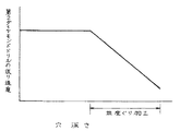
一方、上述した実施の形態のように上穴48を定圧加工した場合、第2ダイヤモンドドリル50の送り速度の変化は図5に示すグラフのようになる。同グラフに示すように、第2ダイヤモンドドリル50の送り速度は、皿座ぐりの開始とともに徐々に低下してゆく。要するに、第2ダイヤモンドドリル50にかかる負荷は、第2ダイヤモンドドリル50とガラス板20との接触面積(≒単位時間当たりのガラス板20の除去体積)にほぼ比例する。したがって、この定圧加工の場合、連通時に生じる罅や割れは防止できるが、1つの孔明加工に要する時間が長くなるという問題がある。
【0037】
そこで、第2の実施の形態の孔明加工方法では、下穴42と連通する直前までは上穴48を定速加工で加工し、連通直前に第2ダイヤモンドドリル50を定圧で送って下穴42と連通させる。
これにより、連通時に生じる罅や割れを効果的に防止しつつ、加工タクトを大幅に向上させることができる。
【0038】
なお、上述した一連の実施の形態では孔82の両側を皿座ぐりする例で説明したが、孔の片側のみを皿座ぐりする場合にも本発明は有効に適用することができる。この場合、初めに皿座ぐりしない穴を形成し、次いで皿座ぐりする穴を形成する。そして、皿座ぐりをしながら互いの穴を連通させる。
また、上述した実施の形態では被加工物としてガラス板20を孔明加工する場合を例に説明したが、被加工物はガラス板に限らず、罅や割れが生じやすい他の高脆性材料を孔明け加工するときにも本発明は有効に適用することができる。
【0039】
【発明の効果】
以上説明したように、本発明によれば皿座ぐりしているときに第1穴と第2穴とを連通させることにより、無理な力をかけずに第1穴と第2穴とを連通させることができる。これにより罅や割れを生じさせることなく孔明け加工することができる。
【図面の簡単な説明】
【図1】ガラス板の孔明加工装置の構成を示す正面図
【図2】本発明に係る孔明加工方法の説明図
【図3】従来の孔明加工方法の説明図
【図4】定速加工時における第2ダイヤモンドドリルに生じる負荷の変化のグラフ
【図5】定圧加工時における第2ダイヤモンドドリルの送り速度の変化のグラフ
【符号の説明】
10…孔明加工装置
12…装置本体
14…クランプ装置
16…下穴加工装置
18…上穴加工装置
20…ガラス板(板状体)
40…第1ダイヤモンドドリル(第1ドリル)
40A…フランジ(拡径部)
50…第2ダイヤモンドドリル(第2ドリル)
50A…フランジ(拡径部)
42…下穴(第1穴)
48…上穴(第2穴)[0001]
BACKGROUND OF THE INVENTION
The present invention relates to a method for drilling a plate-like body, and more particularly to a method for drilling a plate-like body for processing holes in a plate glass.
[0002]
[Prior art]
In the building hazard glass, holes for attaching to the structural frame are drilled in the manufacturing process. These holes are drilled by pressing the diamond drill against the glass plate to give rotation and feed, but to prevent cracking of the glass plate, it is not processed at once but twice from both sides of the glass plate. The method of processing is divided into two.
[0003]
That is, as shown in FIG. 3A, first, a rotating diamond drill 2A is pressed against the lower surface 1A of the glass plate 1 to form a pilot hole 3A, and then, as shown in FIG. A rotating
[0004]
[Problems to be solved by the invention]
However, as shown in FIG. 3C, the conventional processing method has a drawback that wrinkles easily enter the communicating portion when communicating the
This invention is made | formed in view of such a situation, and it aims at providing the punching method of the plate-shaped body which can be drilled without producing a crack and a flaw.
[0005]
[Means for Solving the Problems]
In order to achieve the above object, the present invention forms a first hole having a predetermined depth by pressing against one side surface of a plate-like body while rotating a first drill, and then taper from a tip to a position of a predetermined length. A second drill formed with a large-diameter enlarged portion is pressed against the other side surface of the plate-like body while rotating to form a second hole, and the second hole is formed on one side surface of the plate-like body In the drilling method of the plate-like body that is communicated with the first hole and is countersunk at the enlarged diameter portion, the second hole is formed when the enlarged diameter portion of the second drill is countersunk. while being processed so as to communicate with the first hole, and wherein the Turkey is drilled by pressure processing until communication with the first hole.
In order to achieve the above object, the present invention forms a first hole having a predetermined depth by pressing against one side surface of the plate-like body while rotating the first drill, and then a position having a predetermined length from the tip. A second drill having a tapered enlarged diameter portion formed thereon is rotated against the other side surface of the plate-like body to form a second hole, and the second hole is formed on one side surface of the plate-like body. In the drilling method of the plate-like body that communicates with the first hole formed in the plate and is countersunk at the enlarged diameter portion, the second hole is when the enlarged diameter portion of the second drill is countersunk. Are drilled by constant-speed machining until just before communicating with the first hole, and drilled by constant-pressure machining immediately before communicating with the first hole. It is characterized by that.
[0006]
According to the present invention, the first hole and the second hole communicate with each other when the enlarged diameter portion of the second drill is countersunk the second hole. By drilling in this way, the pressing force applied to the second drill can be received by the tip surface of the drill and the tapered surface of the enlarged diameter portion, and without applying excessive force, The second hole can communicate with the second hole. As a result, it is possible to perform drilling without causing wrinkles or cracks.
[0007]
DETAILED DESCRIPTION OF THE INVENTION
A preferred embodiment of a plate-like body drilling method according to the present invention will be described in detail with reference to the accompanying drawings.
FIG. 1 is a front view showing a configuration of a glass
[0008]
The
The
[0009]
In the
[0010]
The pilot
The
[0011]
The prepared
Here, as shown in FIG. 2A, the
[0012]
Although not shown, an insertion hole is formed in the
The upper
[0013]
The
[0014]
A
[0015]
Here, a
[0016]
A
[0017]
By the way, the second feed table 54 is lowered along with the lowering of the
[0018]
Note that a tactile sensor (not shown) is installed on the upper surface of the
The upper
[0019]
That is, when performing constant speed machining, the
[0020]
On the other hand, constant pressure machining is performed as follows. First, the second feed table 54 is lowered at a constant speed with no pressure applied. That is, the
[0021]
When the release of the contact state between the
[0022]
Since the
By repeating the above, a constant pressing force is always applied to the tip of the
[0023]
As described above, the upper
Further, as shown in FIG. 2 (a), similarly to the even
[0024]
The position of the
[0025]
For example, as shown in FIG. 2C, if the distance from the tip surface of the
[0026]
The drilling method according to the present invention using the
First, the
[0027]
Next, the
[0028]
Next, the first motor 44 is driven to rotate the
[0029]
As the drilling of the
When the
[0030]
Next, the
[0031]
That is, as described above, the
[0032]
As described above, when the
[0033]
When the
Thus, the drilling process is completed, and the
[0034]
As described above, according to the drilling method according to the present invention, the
Next, a second embodiment of the drilling method according to the present invention will be described.
[0035]
In the above embodiment, the
When the
[0036]
On the other hand, when the
[0037]
Therefore, in the drilling method of the second embodiment, the
Thereby, the processing tact can be greatly improved while effectively preventing wrinkles and cracks generated during communication.
[0038]
In the series of embodiments described above, an example in which both sides of the
In the above-described embodiment, the case where the
[0039]
【The invention's effect】
As described above, according to the present invention, the first hole and the second hole are communicated with each other without applying an excessive force by communicating the first hole and the second hole when the countersink is countersunk. Can be made. As a result, drilling can be performed without causing wrinkles or cracks.
[Brief description of the drawings]
FIG. 1 is a front view showing the configuration of a glass plate drilling apparatus. FIG. 2 is an explanatory diagram of a drilling method according to the present invention. FIG. 3 is an explanatory diagram of a conventional drilling method. Graph of change in load generated in second diamond drill in Fig. 5 Fig. 5 Graph of change in feed speed of second diamond drill during constant pressure machining
DESCRIPTION OF
40 ... 1st diamond drill (1st drill)
40A ... Flange (expanded part)
50 ... Second diamond drill (second drill)
50A ... Flange (expanded part)
42 ... Pilot hole (1st hole)
48 ... Upper hole (second hole)
Claims (2)
前記第2穴は、前記第2ドリルの拡径部が皿座ぐりしているときに前記第1穴と連通するように加工されるとともに、前記第1穴と連通されるまで定圧加工により穴明けされることを特徴とする板状体の孔明加工方法。A first hole having a predetermined depth is formed by pressing the first drill against one side surface of the plate-like body while rotating the first drill, and then a tapered enlarged diameter portion is formed at a position of a predetermined length from the tip. A second hole is formed by pressing against the other side surface of the plate-like body while rotating a drill, and the second hole is communicated with the first hole formed on one side surface of the plate-like body and the diameter-expanded In the drilling method of the plate-like body that goes countersunk in the part,
The second hole is processed so as to communicate with the first hole when the diameter-expanded portion of the second drill is countersunk, and is formed by constant pressure processing until the second hole communicates with the first hole. opened by perforated processing method of the plate-like body, wherein the Turkey.
前記第2穴は、前記第2ドリルの拡径部が皿座ぐりしているときに前記第1穴と連通するように加工されるとともに、前記第1穴と連通される直前まで定速加工により穴明けされ、前記第1穴と連通される直前以降、定圧加工により穴明けされることを特徴とする板状体の孔明加工方法。 A first hole having a predetermined depth is formed by pressing the first drill against one side surface of the plate-like body while rotating the first drill, and then a tapered enlarged diameter portion is formed at a position of a predetermined length from the tip. A second hole is formed by pressing against the other side surface of the plate-like body while rotating a drill, and the second hole is communicated with the first hole formed on one side surface of the plate-like body and the diameter-expanded In the drilling method of the plate-like body that goes countersunk in the part,
The second hole is processed so as to communicate with the first hole when the diameter-expanded portion of the second drill is countersunk, and constant-speed machining until immediately before the second hole is communicated with the first hole. by being drilled, said first bore and communicating since the last being passed, drilled by a perforated processing method of the plate-like body you wherein Rukoto by pressure processing.
Priority Applications (1)
| Application Number | Priority Date | Filing Date | Title |
|---|---|---|---|
| JP34152098A JP4352437B2 (en) | 1998-12-01 | 1998-12-01 | Drilling method for plate-like body |
Applications Claiming Priority (1)
| Application Number | Priority Date | Filing Date | Title |
|---|---|---|---|
| JP34152098A JP4352437B2 (en) | 1998-12-01 | 1998-12-01 | Drilling method for plate-like body |
Publications (3)
| Publication Number | Publication Date |
|---|---|
| JP2000158395A JP2000158395A (en) | 2000-06-13 |
| JP2000158395A5 JP2000158395A5 (en) | 2005-10-27 |
| JP4352437B2 true JP4352437B2 (en) | 2009-10-28 |
Family
ID=18346711
Family Applications (1)
| Application Number | Title | Priority Date | Filing Date |
|---|---|---|---|
| JP34152098A Expired - Fee Related JP4352437B2 (en) | 1998-12-01 | 1998-12-01 | Drilling method for plate-like body |
Country Status (1)
| Country | Link |
|---|---|
| JP (1) | JP4352437B2 (en) |
Families Citing this family (8)
| Publication number | Priority date | Publication date | Assignee | Title |
|---|---|---|---|---|
| JP4079152B2 (en) * | 2005-01-25 | 2008-04-23 | 旭硝子株式会社 | How to make a donut glass substrate |
| JP4566840B2 (en) * | 2005-06-30 | 2010-10-20 | Agcテクノグラス株式会社 | Reflector mirror drilling method |
| JP4602224B2 (en) * | 2005-10-27 | 2010-12-22 | Agcテクノグラス株式会社 | Reflector mirror drilling method |
| JP5144909B2 (en) * | 2006-08-11 | 2013-02-13 | 剛 蓮野 | Hole drilling method for plate |
| KR101232926B1 (en) * | 2006-10-13 | 2013-02-13 | 아사히 가라스 가부시키가이샤 | Method of boring glass substrate and glass substrate for plasma display manufactured by the method |
| JP6261286B2 (en) * | 2013-11-01 | 2018-01-17 | 中村留精密工業株式会社 | Hard brittle plate drilling device |
| JP6871031B2 (en) * | 2017-03-23 | 2021-05-12 | 株式会社ミツバ | Worm processing equipment and worm processing method |
| CN111113690B (en) * | 2020-01-13 | 2021-09-17 | 浙江蓝炬星电器有限公司 | Hole forming device and hole forming method for glass table top furnace head hole of integrated stove |
-
1998
- 1998-12-01 JP JP34152098A patent/JP4352437B2/en not_active Expired - Fee Related
Also Published As
| Publication number | Publication date |
|---|---|
| JP2000158395A (en) | 2000-06-13 |
Similar Documents
| Publication | Publication Date | Title |
|---|---|---|
| JP4352437B2 (en) | Drilling method for plate-like body | |
| CN211332305U (en) | Movable automatic clamping and overturning bracket | |
| JP4567298B2 (en) | Method and apparatus for drilling glass plate | |
| CN106827253B (en) | A kind of automatic punch and boring method | |
| JP2003039122A (en) | Apparatus and method for blanking micro pore | |
| US20080056833A1 (en) | Drilling apparatus | |
| JP3215572B2 (en) | Spindle rising end setting device when moving processing position in printed circuit board processing device | |
| JP2520166B2 (en) | Printed circuit board processing method and processing apparatus | |
| KR100901665B1 (en) | Angle Processing Device | |
| WO2002007907A3 (en) | Method and forming machine for deforming a hollow workpiece | |
| JPH0871823A (en) | Boring device | |
| JP2001071323A (en) | Device for holinig sheet glass | |
| JPH04171159A (en) | Automatic control type cutting device and guide pin positioning mark cutting device for multi-layer printed wiring board | |
| JPH0448885Y2 (en) | ||
| JP3163348B2 (en) | Shaped steel processing machine | |
| CN113976936B (en) | Online plate punching equipment and control method thereof | |
| JPH02116458A (en) | Control method for work tool in ultrasonic machine | |
| CN218476931U (en) | Hole punching machine for corner holes of billiard table surface | |
| JPH11114903A (en) | Device for forming vertical hole in wood | |
| JPH0929521A (en) | Underside supporting device for shape steel drilling machine | |
| CN107838273A (en) | A kind of cylindrical material hole punched device | |
| JPH0327769Y2 (en) | ||
| JPH09174496A (en) | Ultrasonic drilling device | |
| JPH06210623A (en) | Boring device of panel and method thereof | |
| JPH0715628Y2 (en) | Release amount setting device for feed roll device |
Legal Events
| Date | Code | Title | Description |
|---|---|---|---|
| A521 | Written amendment |
Free format text: JAPANESE INTERMEDIATE CODE: A523 Effective date: 20050722 |
|
| A621 | Written request for application examination |
Free format text: JAPANESE INTERMEDIATE CODE: A621 Effective date: 20051025 |
|
| A977 | Report on retrieval |
Free format text: JAPANESE INTERMEDIATE CODE: A971007 Effective date: 20080529 |
|
| A131 | Notification of reasons for refusal |
Free format text: JAPANESE INTERMEDIATE CODE: A131 Effective date: 20080605 |
|
| A521 | Written amendment |
Free format text: JAPANESE INTERMEDIATE CODE: A523 Effective date: 20080728 |
|
| A521 | Written amendment |
Free format text: JAPANESE INTERMEDIATE CODE: A523 Effective date: 20080729 |
|
| A131 | Notification of reasons for refusal |
Free format text: JAPANESE INTERMEDIATE CODE: A131 Effective date: 20080930 |
|
| A521 | Written amendment |
Free format text: JAPANESE INTERMEDIATE CODE: A523 Effective date: 20081113 |
|
| TRDD | Decision of grant or rejection written | ||
| A01 | Written decision to grant a patent or to grant a registration (utility model) |
Free format text: JAPANESE INTERMEDIATE CODE: A01 Effective date: 20090706 |
|
| A01 | Written decision to grant a patent or to grant a registration (utility model) |
Free format text: JAPANESE INTERMEDIATE CODE: A01 |
|
| A61 | First payment of annual fees (during grant procedure) |
Free format text: JAPANESE INTERMEDIATE CODE: A61 Effective date: 20090719 |
|
| FPAY | Renewal fee payment (event date is renewal date of database) |
Free format text: PAYMENT UNTIL: 20120807 Year of fee payment: 3 |
|
| S531 | Written request for registration of change of domicile |
Free format text: JAPANESE INTERMEDIATE CODE: R313531 |
|
| R371 | Transfer withdrawn |
Free format text: JAPANESE INTERMEDIATE CODE: R371 |
|
| FPAY | Renewal fee payment (event date is renewal date of database) |
Free format text: PAYMENT UNTIL: 20120807 Year of fee payment: 3 |
|
| S531 | Written request for registration of change of domicile |
Free format text: JAPANESE INTERMEDIATE CODE: R313531 |
|
| FPAY | Renewal fee payment (event date is renewal date of database) |
Free format text: PAYMENT UNTIL: 20120807 Year of fee payment: 3 |
|
| R350 | Written notification of registration of transfer |
Free format text: JAPANESE INTERMEDIATE CODE: R350 |
|
| FPAY | Renewal fee payment (event date is renewal date of database) |
Free format text: PAYMENT UNTIL: 20130807 Year of fee payment: 4 |
|
| LAPS | Cancellation because of no payment of annual fees |