JP4352369B2 - Game machine - Google Patents
Game machine Download PDFInfo
- Publication number
- JP4352369B2 JP4352369B2 JP2002181884A JP2002181884A JP4352369B2 JP 4352369 B2 JP4352369 B2 JP 4352369B2 JP 2002181884 A JP2002181884 A JP 2002181884A JP 2002181884 A JP2002181884 A JP 2002181884A JP 4352369 B2 JP4352369 B2 JP 4352369B2
- Authority
- JP
- Japan
- Prior art keywords
- game
- display
- symbol
- endless belt
- gaming machine
- Prior art date
- Legal status (The legal status is an assumption and is not a legal conclusion. Google has not performed a legal analysis and makes no representation as to the accuracy of the status listed.)
- Expired - Fee Related
Links
Images


Description
【0001】
【発明の属する技術分野】
本発明は、遊技機に関するものである。
【0002】
【従来の技術】
遊技機の一種として、複数の図柄が円環状のリール表面に付されて構成された図柄列を可変表示した後に停止図柄を表示する可変表示手段を備えたスロットマシン等が知られている。この種の遊技機としては、可変表示手段の所定領域である有効ラインに表示される停止図柄が特定図柄である場合に、例えばビッグボーナスゲームのような遊技者に有利な所定のゲーム(特別遊技状態)が発生するものが提供されている。かかるスロットマシンでは、遊技媒体として例えばメダルを使用することが一般的である。すなわち、ゲーム毎に1枚乃至3枚のメダルの投入が行われ、かかる投入によりリールの回転等の所謂ゲームの開始が許容される。
【0003】
また、複数の図柄がリールまたはベルト表面に付されて構成された図柄列を可変表示した後に停止図柄を表示する可変表示手段を備えたパチンコ遊技機が知られている。この種の遊技機としては、可変表示手段の所定領域である有効ラインに表示される停止図柄が特定図柄である場合に、例えば大入賞口が開放する大当りのような遊技者に有利な所定のゲーム(特別遊技状態)が発生するものが提供されている。
【0004】
さらに、近年、メダルの代わりに、パチンコ機で使用される遊技球を用いて上記スロットマシンのような遊技を行うことの可能な遊技機が考えられている。かかる遊技機においては、所定数の遊技球が取り込まれた上でレバー操作が行われることで可変表示手段の可変表示が開始される。また、特別遊技状態の発生に際しては多くの遊技球が払い出される。かかる遊技機をスロットマシンに代えて使用すれば、パチンコホール等の遊技ホールでは遊技球を共通の遊技媒体として取り扱うことができる。そのため、パチンコ機とスロットマシンとが混在している現在の遊技ホールにおいて多く見られる、メダルと遊技球との別個の取扱による設備上の負担や遊技機設置個所の制約といった問題を解消し得る。
【0005】
【発明が解決しようとする課題】
ところが、上記各種遊技機においては、可変表示手段に円環状のリールを用いると遊技機の奥行きが大きくなってしまう不都合がある。また、円環状のリールではリール設置領域が大きくなり、他の遊技機器、例えば電気的表示装置の設置領域が小さくなったり、同表示装置を遊技者に見やすい位置に設置できない等の不都合が生じる。
【0006】
本発明は、上記事情に鑑みてなされたものであり、その主たる目的は、遊技機の厚みを少なくしてコンパクトにし、または図柄を機械的に可変表示する可変表示手段の占有領域を小さくして他の遊技機器の設置スペースを確保し得る遊技機を提供することにある。
【0007】
また、特に、遊技球を取り込んだ上で一遊技回を実行することのできるタイプの遊技機においては、パチンコ機と同一の島に設置される関係上、当該遊技機の奥行きを小さくすることを目的の一つとし、このように遊技機の奥行きを小さくしてもなお遊技の興趣を損なわないようにすることを目的とする。
【0008】
【課題を解決するための手段及びその効果】
上記の課題を解決するために有効な手段等を以下に示す。なお、必要に応じて各手段の直後に作用、効果等をそれぞれ記載する。
【0009】
手段1.表面に図柄が付された無端状ベルトを周回させるように構成するとともに、無端状ベルトの一部を視認できるように表示窓が設けられ、当該表示窓から前記図柄を視認できるようにした遊技機において、
前記無端状ベルトのうち、表示窓から視認される部分を、当該ベルトの回転方向において表示窓側に凸となるように巻回したことを特徴とする遊技機。
【0010】
無端状ベルトを利用することで、断面円形(円環状)のリールによって図柄変動領域を形成するよりも、遊技機の厚みを抑えることができる。しかし、無端状ベルトを利用すると、表示窓から視認される図柄の変動態様は平面的になってしまい、遊技者にとってはベルト回転中の図柄を目で追い難くなる。この点、本手段では、表示窓から視認される部分を表示窓側に凸となるように無端状ベルトの常態を構成したことから、遊技機の厚みを抑えつつも、遊技者がベルト回転中の図柄を目で追い易くなる。
【0011】
手段2.表面に図柄が付された無端状ベルトを周回させるように構成するとともに、無端状ベルトの一部を視認できるように表示窓が設けられ、当該表示窓から前記図柄を視認できるようにした遊技機において、
前記無端状ベルトを扁平状に周回させ、かつ、前記無端状ベルトのうち表示窓から視認される部分を当該ベルトの回転方向において表示窓側に凸となるように構成したことを特徴とする遊技機。
【0012】
無端状ベルトを利用して扁平状に周回させることで、断面円形のリールによって図柄変動領域を形成するよりも、遊技機の厚みを抑えることができる。しかし、無端状ベルトを扁平状に周回させると、表示窓から視認される図柄の変動態様は平面的になってしまい、遊技者にとってはベルト回転中の図柄を目で追い難くなる。この点、本手段では、無端状ベルトのうち表示窓から視認される部分については表示窓側に凸となるように構成したことから、遊技機の厚みを抑えつつも、遊技者がベルト回転中の図柄を目で追い易くなる。
【0013】
なお、以上の手段1,2において、手段5乃至手段11のいずれかの構成を適用してもよい。
【0014】
手段3.遊技球を取り込む取込手段を備え、所定数の遊技球が取り込まれると、表面に図柄が付された無端状ベルトを回転させて停止させる一遊技回の遊技を実行し得るとともに、無端状ベルトの一部を視認できるように表示窓が設けられて当該表示窓から前記図柄を視認できるようにした遊技機において、
前記無端状ベルトのうち、表示窓から視認される部分を、当該ベルトの回転方向において表示窓側に凸となるように構成したことを特徴とする遊技機。
【0015】
無端状ベルトを利用することで、断面円形のリールによって図柄変動領域を形成するよりも、遊技機の厚みを抑えることができる。しかし、無端状ベルトを利用すると、表示窓から視認される図柄の変動態様は平面的になってしまい、遊技者にとってはベルト回転中の図柄を目で追い難くなる。この点、本手段では、表示窓から視認される部分を表示窓側に凸となるように無端状ベルトの常態を構成したことから、遊技機の厚みを抑えつつも、遊技者がベルト回転中の図柄を目で追い易くなる。
【0016】
手段4.遊技球を取り込む取込手段を備え、所定数の遊技球が取り込まれると、表面に図柄が付された無端状ベルトを回転させて停止させる一遊技回の遊技を実行し得るとともに、無端状ベルトの一部を視認できるように表示窓が設けられて当該表示窓から前記図柄を視認できるようにした遊技機において、
前記無端状ベルトを扁平状に周回させ、かつ、前記無端状ベルトのうち表示窓から視認される部分を当該ベルトの回転方向において表示窓側に凸となるように構成したことを特徴とする遊技機。
【0017】
無端状ベルトを利用して扁平状に周回させることで、断面円形のリールによって図柄変動領域を形成するよりも、遊技機の厚みを抑えることができる。しかし、無端状ベルトを扁平状に周回させると、表示窓から視認される図柄の変動態様は平面的になってしまい、遊技者にとってはベルト回転中の図柄を目で追い難くなる。この点、本手段では、無端状ベルトのうち表示窓から視認される部分については表示窓側に凸となるように構成したことから、遊技機の厚みを抑えつつも、遊技者がベルト回転中の図柄を目で追い易くなる。
【0018】
なお、以上の手段1乃至手段4において、無端状ベルトの表示窓側への凸形状は、円弧状に凸となる形状であることが好ましい。このように構成すれば、無端状ベルトの変形による疲労が軽減されるとともに、ベルト回転時の図柄の可変表示が滑らかなものとなって違和感がなくなる。
【0019】
手段5.手段2または手段4において、前記無端状ベルトの前記凸となる部分に隣接する位置には、前記無端状ベルトの扁平方向に沿って、平板状の電気的表示装置を配置したことを特徴とする遊技機。
【0020】
手段5によれば、無端状ベルトの凸となる部分に隣接して形成される空間に、電気的表示装置を略平行に配置することによって、遊技機の厚みを増加させることなく、電気的表示装置を遊技機の中心的位置に配置することができる。この場合、無端状ベルトと電気的表示装置とが全体として直方体空間に収まるように配置されることが好ましく、これにより表示演出系の装置類のコンパクト化を図ることができる。
【0021】
手段6.手段5において、前記無端状ベルト及びその駆動系と、前記電気的表示装置とは、一体的に組み立てられて表示装置ユニットを構成しており、当該表示装置ユニットが遊技機本体に取り付けられるものであることを特徴とする遊技機。
【0022】
手段6によれば、無端状ベルト及びその駆動系と、電気的表示装置とがユニットを構成しており、一体物として遊技機本体に取り付けられることから、それらを別々に組み付ける場合に比べて組み付けが容易である。
【0023】
手段7.遊技球を取り込む取込手段を備え、所定数の遊技球が取り込まれると、表面に図柄が付された無端状ベルトを回転させて停止させる一遊技回の遊技を実行し得るとともに、無端状ベルトの一部を視認できるように表示窓が設けられて当該表示窓から前記図柄を視認できるようにした遊技機において、
前記無端状ベルトを小径ローラと大径ローラとに掛け渡して、無端状ベルトの大径ローラに掛け渡された部分を前記表示窓に対応配置したことを特徴とする遊技機。
【0024】
無端状ベルトを一対のローラに掛け渡すこと等によって、断面円形のリールによって図柄変動領域を形成するよりも、遊技機の厚みを抑えることができる。しかし、無端状ベルトを掛け渡すローラとして同一径のものを利用して遊技機の厚みを抑えようとすると、表示窓から視認される図柄の変動態様は平面的になってしまい、遊技者にとってはベルト回転中の図柄を目で追い難くなる。この点、本手段では、無端状ベルトが掛け渡されるローラとして径の異なるものを利用して表示窓から視認される領域を大径ローラに掛け渡された部分によって構成したことから、遊技機の厚みを抑えつつも、遊技者がベルト回転中の図柄を目で追い易くなる。
【0025】
手段8.手段7において、無端状ベルトの表示窓側における前記両ローラに掛け渡されている領域のうち、大径ローラ寄りには、無端状ベルトを大径ローラ側に押える押えローラを設けたことを特徴とする遊技機。
【0026】
手段8によれば、押えローラによって、無端状ベルトは大径ローラに沿った部分がひろがり、表示窓から見えるベルトに十分な奥行き感が生じ、遊技者がベルト回転中の図柄を一層目で追い易くなる。
【0027】
手段9.手段8において、前記押えローラよりも小径ローラ側には、前記無端状ベルトに沿って平板状の電気的表示装置を配置したことを特徴とする遊技機。
【0028】
手段9によれば、押えローラよりも小径ローラ側に形成される空間に、電気的表示装置を略平行に配置することによって、遊技機の厚みを増加させることなく、電気的表示装置を遊技機の中心的位置に配置することができる。この場合、無端状ベルトと電気的表示装置とが全体として直方体空間に収まるように配置されることが好ましく、これにより表示演出系の装置類のコンパクト化を図ることができる。
【0029】
手段10.手段9において、前記無端状ベルト及び前記各ローラと、前記電気的表示装置とは、一体的に組み立てられて表示装置ユニットを構成しており、当該表示装置ユニットが遊技機本体に取り付けられるものであることを特徴とする遊技機。
【0030】
手段10によれば、無端状ベルト及び各ローラと、電気的表示装置とがユニットを構成しており、一体物として遊技機本体に取り付けられることから、それらを別々に組み付ける場合に比べて組み付けが容易である。
【0031】
手段11.手段7乃至手段10のいずれかにおいて、前記小径ローラがモータ等の電気的駆動源に連結された駆動ローラであり、他のローラが従動ローラであることを特徴とする遊技機。
【0032】
手段11によれば、無端状ベルトのうち表示窓に臨む部分である大径ローラを従動ローラとしたことから、大径ローラ内に蛍光ランプ等のバックライトを配置することができる利点がある。
【0033】
手段12.手段1乃至手段11のいずれかにおいて、前記表示窓から視認される前記図柄の停止状況に応じて遊技者に遊技価値を付与するようにしたことを特徴とする遊技機。
【0034】
手段12によれば、図柄停止状況に応じて遊技者に付与される遊技価値が決定されることから、遊技の興趣を高めることができる。
【0035】
手段13.手段1乃至手段12のいずれかにおいて、前記無端状ベルトは複数並設されていることを特徴とする遊技機。
【0036】
手段13によれば、無端状ベルトが複数並設されていることから、それぞれに付された図柄のベルト停止時の組合せによって、遊技者に付与する遊技価値を変化させることができる。また、前記電気的表示装置を設置する場合にあっては、その幅を並設方向に広げることができ、特にベルトとともにユニット化する際には複数のベルト列と略同一幅とすることがコンパクトさ等の面で最も有利である。
【0037】
手段14.手段1乃至手段13のいずれかにおいて、始動操作手段の操作に起因して前記ベルトの回転を始動させて図柄を可変表示するとともに、停止操作手段の操作に起因して或いは該停止操作手段が操作されないまま所定時間経過したことに起因して前記ベルトの回転を停止させて図柄の可変表示を停止するように構成したことを特徴とする遊技機。
【0038】
手段14によれば、遊技者が始動操作手段を操作したり停止操作手段を操作することにより、遊技に積極的に関与することができる。そして、停止操作手段を操作するに際して、以上の各手段のように無端状ベルトに付された図柄の視認性が向上していることで、遊技の興趣を損なうことがない。
【0039】
手段15.手段1乃至手段14のいずれか(電気的表示装置について説明されていない手段を除く)において、前記電気的表示装置は、内部抽選によって既に遊技者に有利な遊技価値を付与する図柄で停止し得る状態にあることを示す情報を付与するものであることを特徴とする遊技機。
【0040】
手段15によれば、電気的表示装置は、内部抽選によって当選していることを示す情報(例えばビッグボーナスフラグが成立していることを示す情報)を付与することから、遊技者は遊技球の取り込みの最中にそのような情報が導き出されることに強い感心を持つこととなり、遊技球の取り込み最中の待ち時間を有意義に過ごすことができる。
【0041】
ここで、かかる情報を明示することも可能であるが、遊技球の取り込み待ち時間が数秒ある場合においてその待ち状態を退屈させないためには、かかる情報を得るための手がかりを与える程度の付与が好ましい。例えば、所定のゲームを進行させてゲームが成立したら内部抽選で所定の当選がなされていることが遊技者にわかるようにする等である。
【0042】
手段16.手段1乃至手段15のいずれかにおいて、遊技球を保持する球受皿を備え、球受皿の球受面を、取込手段に遊技球を供給するように当該取込手段側へ傾斜させたことを特徴とする遊技機。
【0043】
手段16によれば、球受皿に保持された遊技球が当該球受皿の球受面の傾斜により取込手段に供給される。従って、球受皿に遊技球を入れておけば、取込手段によって次々と遊技球の取込処理を行うことができる。
【0044】
手段17.手段12において、前記遊技価値の付与は、払出手段による遊技球の払出によって実行されることを特徴とする遊技機。
【0045】
手段17によれば、遊技の開始の際も遊技価値の付与の際も共通の遊技球を使用しているから、パチンコ機の島で島設備を完全に共有化することができる。
【0046】
手段18.手段16と手段17との組み合わせにおいて、払出手段を球受皿、特に球受皿の傾斜上流側に遊技球を払い出すように構成したことを特徴とする遊技機。
【0047】
手段18によれば、払出手段からの遊技球が球受皿に受け入れられ、その遊技球が傾斜によって取込手段に取込まれるため、遊技者が積極的に遊技球を球受皿に持っていく手間が軽減される利点がある。
【0048】
手段19.手段1または手段2において、遊技機は、発射された遊技球が落下する遊技領域を備え、遊技領域の一部に前記表示窓が設けられているパチンコ機であること。
【0049】
手段19によれば、遊技領域の一部に可変表示手段であるベルトの表示窓が形成されている関係上、表示窓の設置領域が小さく、またホールの島設備に設置する関係上、パチンコ機の厚みも大きくできないが、本手段によれば、ベルトの占有領域を小さくしつつ、図柄の大きさを小さくすることなく図柄数を多くすることができる等の利点がある。
【0050】
【発明の実施の形態】
以下に、遊技球を取り込んだ上で遊技が開始される遊技機を具体化した一実施の形態につき図面に基づいて説明する。
【0051】
なお、本実施の形態における遊技機は、基本的な遊技内容についてはいわゆるスロットマシンと似通った性質を具備するものである。但し、遊技に際しては所定数の遊技媒体(遊技価値)としての遊技球(パチンコ機と同様の遊技球:パチンコ球)を必要とし、所定条件が成立した場合には複数の遊技球、場合によっては大量の遊技球が払い出されるよう構成されている。
【0052】
図1に示すように、遊技機10は、矩形状の外枠1と、外枠1の前部に設けられ外枠1の一側部にて開閉可能に支持された前面枠2とを備えている。本実施の形態では、基本的には外枠1及び前面枠2により遊技機本体が構成されている。
【0053】
前面枠2の前面側には、前面扉3が開閉可能に設けられている。前面扉3が閉状態となっている場合、該前面扉3によって前面枠2の下部を除く部分が閉鎖される。また、該前面扉3は、自身が閉状態にある場合には図示しないロック機構によって開放不能な状態にロックされており、そのロック状態は前面扉3に設けられた図示しないキーシリンダに対する所定のキー操作によって解除されるように構成されている。
【0054】
上述したように、本実施の形態における遊技機1は、遊技球(仮想遊技球をも含む)の投入を必要条件として遊技が行われるよう構成されている。すなわち、前記前面扉3の裏側には、遊技者の投入操作やクレジット操作等に基づいて遊技球を所定個数ずつ取込むための取込手段としての取込装置4(図7参照)が設けられている。また、所定条件成立に基づいて遊技球の払出が行われるようになっている。すなわち、前記前面枠2の裏側には、図6に示すように、裏セット盤5が取着されており、該裏セット盤5には、払出用の遊技球を貯留するためのタンク6、該タンク6に連接されたタンクレール7及びケースレール8、ケースレール8に連接された払出手段としての払出装置9、並びに、払出装置9から延びる払出通路11等が設けられている。
【0055】
また、図1,2に示すように、前面枠2の下部には、遊技者側において遊技球を貯留可能な上受皿12が着脱自在に取付けられている。一方、前面扉3のうち、前記上受皿12に対応する部分は前面側に膨出しており、かつ、その上下が開口形状となっている。このため、前面扉3が閉状態にあるときには、上受皿12、特にその上面側が、露出するよう構成されている。かかる構成により、上受皿12を容易に取り外すことができるとともに、取り外した上で、清掃等の作業を行いやすくなっている。また、後述する操作部14等の点検、修理等を前面扉3の裏側から行いやすくなっている。つまり、メンテナンス性の向上が図られている。
【0056】
そして、前記投入操作が行われた場合、取込装置4が作動し、これにより上受皿12にある遊技球が、図の右側から所定個数ずつ取り込まれるようになっている。また、所定条件が成立した場合には、前記払出装置9が作動し、これにより、タンク6に貯留されている遊技球が、払出通路11等を介して基本的には前記上受皿12に払い出されるようになっている。ここで、上受皿12は、払出装置9から払い出される遊技球を取込装置4の方へ向けて案内するべく、払出口から取込装置4側へと幾分下方傾斜するように形成されている。図1では、上受皿4の上面(球受面)は右側へと下方傾斜している。
【0057】
上受皿12の下方において、前面枠2の下部には、下受皿13が設けられている。そして、前記上受皿12内に遊技球が満タンに貯留されている状態であって、さらに遊技球の払出が行われた場合には、下受皿13の方へと遊技球が払い出されるようになっている。
【0058】
前記上受皿12に対応する部位において、前記前面扉3の膨出部分は、操作部14となっている。また、前面扉3のうち、操作部14の直上には、表示部15が設けられている。これら操作部14及び表示部15の構成については後述することとする。
【0059】
前面扉3には、前記表示部15の上方において、3つの表示窓21,22,23が横並びとなるように設けられている。表示窓21,22,23は透明又は半透明な材質により構成されており、各表示窓21,22,23を通して内部を視認可能な状態とされている。また、各表示窓21,22,23の上方には、補助表示窓24が設けられている。これら表示窓21,22,23及び補助表示窓24並びにこれらを含む領域は、パネル状をなしており、遊技者に視認されやすいよう、下方ほど手前となるように傾斜して形成されている(図5参照)。
【0060】
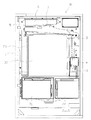
図2,5に示すように、前面扉3の裏側において、前面枠4には、表示装置ユニット30が設置されている。表示装置ユニット30は、前面枠4に取着固定された支持フレーム40を具備している。支持フレーム40には、可変表示手段を構成する左回転体31、中回転体32及び右回転体33が収納されている。本実施の形態において、各回転体31,32,33は、複数の外歯を等間隔に有してなる駆動ローラ34と、駆動ローラ34よりも大径で複数の外歯を等間隔に有してなる従動ローラ35と、両ローラ34,35の外歯に掛け渡されたベルト(無端状ベルト)36とを備えている。かかる構成下、円形状のリールで回転体を構成した場合とは異なり、ベルト36(回転体31,32,33)は、扁平状に構成されることとなる。
【0061】
各回転体31,32,33の駆動ローラ34は、表示装置ユニット30の上部において回転可能に軸支されている。また、各駆動ローラ34は、それぞれステッピングモータ等よりなるモータ37,38,39に連結されている。そして、各モータ37,38,39の駆動により各回転体31,32,33が個別に、すなわち、それぞれ独立して回転駆動するようになっている。さらに、各回転体31,32,33の従動ローラ35は、表示装置ユニット30の下部において、前記表示窓21,22,23に相対する位置において回転可能に軸支されている。
【0062】
各従動ローラ35の上方において、該従動ローラ35寄りには、前記ベルト36を前面側から奥側へと押圧するようにして、押えローラ41が従動回転可能に支持されている。該押えローラ41も外歯を有しており、ベルト36の回転に伴って回転させられるようになっている。かかる押えローラ41は、駆動ローラ34よりも小径であって、ベルト36に対し所定のテンションを付与するとともに、前記従動ローラ35に対するベルト36の当接長をより多くするべく機能する。
【0063】
具体的には、押えローラ41が存在することで、ベルト36は、前記従動ローラ35の外周面(円周)上の3分の2程度に当接する。これにより、前記表示窓21,22,23からは、前記ベルト36が、あたかも断面円弧状の湾曲面に沿って(円周上を)回転するかの如く視認されうるようになっている。換言すれば、前記ベルト36のうち、表示窓21,22,23から視認される部分は、ベルト36の回転方向において表示窓21,22,23側に円弧状に凸となるように構成されている。
【0064】
さらに、支持フレーム40には、電気的表示装置を構成する略平板状の液晶表示装置42が装着されている。液晶表示装置42は、前記従動ローラ35の上方、かつ、前記補助表示窓24及びベルト36間において、補助表示窓24及びベルト36と略平行に位置するよう設置されている。つまり、前記補助表示窓24からは、液晶表示装置42の表示面が視認されるようになっている。なお、液晶表示装置42を、前記押えローラ41よりも上方、つまり、駆動ローラ34側に設けることとしてもよい。また、ベルト36と液晶表示装置42とが全体として直方体空間に収まるよう配置されていることが、コンパクト化を図るといった観点からは望ましい。本実施の形態では、これら支持フレーム40、駆動ローラ34、従動ローラ35、ベルト36、モータ37,38,39、押えローラ41及び液晶表示装置42等により表示装置ユニット30が構成されている。
【0065】
さて、回転体31,32,33が回転すると、各表示窓21,22,23を通して回転体31,32,33(各ベルト36)が上から下へ向かって移動しているかのように視認される。図3に示すように、各ベルト36の外表面には、それぞれ識別情報としての図柄(シンボル)が多数付されている。これらの図柄のうち、表示窓21,22,23を介して視認可能な図柄数は、主として表示窓21,22,23の上下方向の長さによって決定される所定数に限られている。本実施の形態では各回転体31,32,33毎に全体を視認可能な図柄数は2個ずつとされている。
【0066】
次に、各回転体31,32,33のベルト36に付される図柄について説明する。図3には、左回転体31、中回転体32、右回転体33のベルト36についての図柄配列が示されている。同図は、ベルト36表面の展開図とみても差し支えない。同図に示すように、各ベルト36にはそれぞれ20個の図柄が一列に設けられている。
【0067】
図柄としては、例えばビッグボーナスゲームに移行するための「7」図柄(上の2つの図柄)がある(ビッグボーナス図柄)。また、リプレイゲームに移行するための「リプレイ」図柄(例えば、上から第3,4番目)がある。併せて、小役の払出が行われる小役図柄としての「タコ」図柄(例えば、上から第9,10番目)がある。なお、本実施の形態では各ベルト36における各図柄の数や配置順序は同じに設定されている。本実施の形態では、上下一対の2つの図柄が組合わさることによって「7」等の絵、模様、数字等が構成されるようになっているが、これらは、同種ではあるがそれぞれ異なる図柄である。例えば、上の2つの「7」図柄は、「7」の数字の上半分で1つの「7」図柄であり、「7」の数字の下半分で1つの「7」図柄を構成する(「リプレイ」図柄、「タコ」図柄も同様)。また、「7」の数字の下半分で構成される「7」図柄は、「タコ」の小さな絵模様が付されており、「タコ」図柄を兼ねている(但し、「7」図柄が3つ揃った場合は、「7」図柄が優先される)。
【0068】
そして、小役図柄に関し、「タコ」図柄が後述する有効ライン上に左・中・右と揃った場合には75個の遊技球の払出が行われ、ビッグボーナス図柄の組合せである「7」図柄が有効ライン上に左・中・右と揃った場合には75個の遊技球の払出が行われる。さらに、「リプレイ」図柄が有効ライン上に左・中・右と揃った場合には遊技球の払出は行われない。なお、本実施の形態では、更なる小役図柄の組合せを設定することとしている。すなわち、有効ライン上において、左・中・右の順に(1)「7」図柄、「7」図柄、「リプレイ」図柄が、(2)「7」図柄、「7」図柄、「タコ」図柄が、(3)「7」図柄、「リプレイ」図柄、「7」図柄が、(4)「7」図柄、「タコ」図柄、「7」図柄が、(5)「リプレイ」図柄、「7」図柄、「7」図柄が、(6)「タコ」図柄、「7」図柄、「7」図柄が揃った場合においても、75個の遊技球の払出が行われるようになっている。
【0069】
図4(a),(b)に示すように、前面扉3には、各表示窓21,22,23を結ぶように、横方向へ平行となるように2本、下上下及び上下上の如く山型、谷型となるように2本、計4本の有効ラインが付されている。勿論、最大有効ライン数を5以上としてもよく、3未満としてもよく、所定条件に応じて最大有効ライン数を変更するようにしてもよい。これら各有効ラインに対応して、表示窓21,22,23群の正面から見て左側にはベット数表示部43が設けられている。
【0070】
ベット数表示部43では、下段の横ライン(下ライン)のみが有効化された場合に「1」のセグメント表示によって報知される。本実施の形態では、前記下ラインが有効化されるためには、5個の遊技球の投入(1ベット)が必要とされる。また、ベット数表示部43では、下ライン及び上段の横ライン(上ライン)のみが有効化された場合に「2」のセグメント表示によって報知される。本実施の形態では、前記上下ラインが有効化されるためには、10個の遊技球の投入(2ベット)が必要とされる。さらに、ベット数表示部43では、上下の横ライン並びに、山形及び谷型(山谷ライン)、つまり計4つのラインが有効化された場合に「3」のセグメント表示によって報知される。本実施の形態では、前記上下ライン及び山谷ラインが有効化されるためには、15個の遊技球の投入(3ベット)が必要とされる。すなわち、本実施の形態では、一遊技回の遊技に必要な最低限の遊技球の数(所定数)は「5個」に設定され、一遊技回の遊技に最大限投入可能な遊技球の数(最大投入数)は「15個」に設定されている。
【0071】
図1に示すように、前記前面扉3の膨出部分に設けられた操作部14の左側には、各回転体31,32,33を一斉(同時である必要はない)に回転開始させるために操作されるスタートレバー44が設けられている。スタートレバー44は可変表示を開始させるべく操作される始動操作手段を構成する。スタートレバー44の右側には、回転している各回転体31,32,33を個別に停止させるために操作されるボタン状のストップスイッチ45,46,47が設けられている。各ストップスイッチ45,46,47は停止対象となる回転体31,32,33に対応する表示窓21,22,23に対応してそれぞれ配置されている。ストップスイッチ45,46,47は、可変表示を停止させる停止手段、及び、可変表示を停止させるべく操作される停止操作手段を構成する。なお、本実施の形態では、前記ストップスイッチ45,46,47が停止されないまま所定時間経過したことに起因して、前記回転体31,32,33が停止させられるよう構成されている。
【0072】
また、前記操作部14のうち、前記スタートレバー44の近傍には、遊技球を投入するための入力手段を構成するボタン状のベットスイッチが設けられている。本実施の形態では、ベットスイッチとして1ベットスイッチ51と、2ベットスイッチ52と、マックスベットスイッチ53とが設けられている。各ベットスイッチ51,52,53は、共に遊技媒体(又は記憶遊技媒体)たる遊技球を投入するためのものである。1ベットスイッチ51に関しては、1回押圧操作される毎に、5個の遊技球が投入されるよう設定されている。より詳しくは、後述するクレジットモード下においてクレジットされた仮想遊技球が所定数(5個)以上存在する場合には、1ベットスイッチ51の1回の押圧操作で、仮想遊技球がそれまでのクレジット数から「5個」だけ減算される。また、仮想遊技球が所定数以下の場合又はクレジットモードでないダイレクトモードの場合には、1ベットスイッチ51の1回の押圧操作で、上受皿12の遊技球が「5個」ずつ回収され、取り込まれるようになっている。
【0073】
また、2ベットスイッチ52に関しては、1回押圧操作される毎に、10個の遊技球が投入されるよう設定されている。より詳しくは、後述するクレジットモード下においてクレジットされた仮想遊技球が所定数(10個)以上存在する場合には、2ベットスイッチ52の1回の押圧操作で、仮想遊技球がそれまでのクレジット数から「10個」だけ減算される。また、仮想遊技球が所定数以下の場合又はクレジットモードでないダイレクトモードの場合には、2ベットスイッチ52の1回の押圧操作で、上受皿12の遊技球が「10個」ずつ回収され、取り込まれるようになっている。
【0074】
さらに、マックスベットスイッチ53は、前記1ベットスイッチ51等の複数回(3回)の押圧操作を省略することができるよう設けられているものであって、1回押圧操作される毎に、15個(3ベット分)の遊技球が投入されるよう設定されている。より詳しくは、後述するクレジットモード下においてクレジットされた仮想遊技球が所定数(15個)以上存在する場合には、マックスベットスイッチ53の1回の押圧操作で、仮想遊技球がそれまでのクレジット数から「15個」だけ減算される。また、仮想遊技球が所定数以下の場合又はクレジットモードでないダイレクトモードの場合には、マックスベットスイッチ53の1回の押圧操作で、上受皿12の遊技球が「15個」ずつ回収され、取り込まれるようになっている。本実施の形態における実際の遊技球の取込は、前述のとおり、取込装置4によって行われる。なお、取込装置4よりも上流側の取込通路(図示略)には、1個1個の遊技球の存在の有無を検出可能なフォトセンサよりなる取込検出センサ96(図7参照)が複数個配設されている。当該検出センサ96の存在によって、1ベット分(5個)、2ベット分(10個)或いはマックスベット分(15個)の遊技球を一度に取込可能か否かを検出できるようになっている。
【0075】
また、本実施の形態では、上下ライン及び山谷ライン(計4ライン)が有効化された(15個の遊技球が投入された)時点で、最大ベット(3ベット)状態となる。つまり、例えば、或いはマックスベットスイッチ53の1回の押圧操作がなされた時点で、それ以上の投入は行われないようになっている。従って、本実施の形態では最大ベット(3ベット)状態となった上で、さらにベットスイッチ51,52,53が押圧操作された場合には、該操作が無効化されるようになっている。
【0076】
さらに、前記操作部14において、スタートレバー44の近傍には、ボタン状の切換スイッチ54が設けられている。また、操作部14の右部には、精算スイッチ55が設けられている。切換スイッチ54は、既に取り込まれ貯留記憶された状態となっている遊技球や、所定条件成立の結果遊技者に払い出される遊技球の取扱形式を変更するために操作される。
【0077】
すなわち、例えば電源投入時には、所定の最大値(例えば遊技球250個分:最大記憶数)となるまでの余剰の遊技球をクレジット(仮想遊技球:記憶遊技媒体)として貯留記憶するとともに、払い出された遊技球もクレジット(仮想遊技球)として貯留記憶するように設定しておく「クレジットモード」とし、切換スイッチ54が押圧操作されると、クレジットがある場合にはその分を現実の遊技球として払い出すとともに、余剰の遊技球や獲得遊技球も現実の遊技球として直接払い出すように設定された「ダイレクトモード」に切り換えられるようにしておく。そして、この切換スイッチ54が操作される度に「クレジットモード」と「ダイレクトモード」とが交互に切り換えられるようにしておけば、遊技者は自身の好みに応じた形式で遊技を実行することができる。かかる切換スイッチ54は投入価値及び遊技価値の取扱形式を切り換える切換操作手段を構成する。
【0078】
また、精算スイッチ55は、上受皿12に貯留されている遊技球を下受皿13に排出するためのものである。すなわち、遊技者が遊技を終了して上受皿12に貯留されていた遊技球を取り出そうとした場合に、当該精算スイッチ55が押圧操作されることで、上受皿12に貯留されている遊技球が下受皿13に排出されるようになっている。もちろん、レバースライド操作によって上受皿12の遊技球が下受皿13に排出される構成であってもよい。
【0079】
さらに、前面扉3の前記表示部15には、クレジットモード時に有効化されて貯留記憶された遊技球数を表示する記憶数表示手段としての残数表示部56と、獲得遊技球の個数を表示する獲得数表示部57と、ビッグボーナスゲーム中の情報(例えばゲーム回数等)を表示するための情報表示部58とがそれぞれ設けられている。本実施の形態では、これら各表示部56,57,58は3桁或いは2桁の7セグメント表示器によって構成されているが、桁数は特に限定されるものではないし、液晶表示器等によって代替することも当然可能である。
【0080】
ところで、本実施の形態においては、前記クレジットモード時における最大貯留記憶個数は上述したように例えば「250個」(50ベット分相当)に設定されている。そして、前記残数表示部56には、「0」〜「250」までの貯留記憶数が表示可能となっている。クレジットモード時においては、この残数表示部56の表示される数字は、1ベット毎に5ずつ(マックスベットでは15ずつ)減算されて表示されることとなる。従って、当該残数表示部56に表示されている数値が5の倍数でない場合には、現時点での貯留記憶数が「0」〜「4」の間の端数分存在していることを遊技者は容易に認識することができる。
【0081】
なお、遊技機1(前面扉3)の上部には、ビッグ報知部、リプレイ報知部、小役報知部等の各種報知部(図示略)が設けられている。これら各種報知部は遊技機1上部以外の場所に設けてもよいし、共通の報知部で異なる態様の報知を行うようにしてもよい。例えば、ビッグ報知部は、各回転体31,32,33の停止時に「7」図柄が有効ライン上に揃った場合、ビッグボーナスゲームを獲得したことを点灯、点滅等によって表示報知する。リプレイ報知部は、各回転体31,32,33の回転停止時に「リプレイ」図柄が有効ライン上に揃った場合、リプレイゲームを獲得したことを点灯、点滅等によって表示報知する。小役報知部は、各回転体31,32,33の回転停止時に小役図柄としての「タコ」図柄或いは前記特殊な小役図柄が有効ライン上に揃った場合、所定数の遊技球を獲得したことを点灯、点滅等によって表示報知する。なお、これら各報知部は表示によって報知することとしたが、これに代えて或いはこれに加えて、遊技機1(前面扉3の上部)に備えられるスピーカ61によって音声により報知してもよい。
【0082】
さらに、表示窓21,22,23の両側及びスピーカ61の上方には、補助演出を行うためのランプ表示部62,63,64が設けられている。該ランプ表示部62,63,64は、例えば、表示内容の多様化及び表示演出の重厚化を意図して設けられており、遊技の進行に伴って各種表示演出を実行するためのものである。例えば、ビッグボーナスゲームを獲得しうる状態になったときに、全てのランプ表示部62,63,64を点灯させることで、遊技者への告知が行われることになっていてもよい。
【0083】
図6,7に示すように、遊技機1の裏セット盤5には、遊技に関する各種の制御を行うための主基板(制御装置)71が備えられている。主基板71は、主たる制御を司るCPU、遊技プログラムを記憶したROM、遊技の進行に応じた必要なデータを記憶するRAM、各種機器との連絡をとるポート、各種抽選の際に用いられる乱数発生器、時間計数や同期を図る場合などに使用されるクロックパルス発生回路等を含む制御回路基板よりなっており、制御基板ボックスに収納されている。また、裏セット盤5には、サブ基板72及び電源基板73等が設けられている。
【0084】
図7は、主基板71等の電気的構成を説明するブロック図である。同図において、太い矢印は、電源の接続及び方向を示し、細い矢印は信号の接続及び方向を示している。電源基板73からの電源は、主基板71及び払出装置9へと供給される。また、サブ基板72へは、主基板71を介して電源が供給される。
【0085】
主基板71の入力側には、スタートレバー44の操作を検出するスタート検出センサ81、各ストップスイッチ45,46,47の操作を個別に検出するストップ検出センサ82,83,84、1ベットスイッチ51の押圧操作を検出する1ベット検出センサ85、2ベットスイッチ52の押圧操作を検出する2ベット検出センサ86、マックスベットスイッチ53の押圧操作を検出するマックスベット検出センサ87、切換スイッチ54の押圧操作を検出する切換検出センサ88、各回転体31,32,33(ベルト36)の回転位置(原点位置)を個別に検出する回転位置検出センサ91,92,93、払出装置9より払い出される遊技球を検出する払出検出センサ94、取込装置4より取込まれる遊技球を検出する前記カウントセンサ95、取込装置4において1ベット分(5個)又はマックスベット分(15個)の遊技球を一度に取込可能か否かを検出するための取込検出センサ96等の各種センサが接続されている。
【0086】
主基板71の出力側には、前記電源基板73を介して前記払出装置9が接続されている。また、この外にも主基板71の出力側には、前記取込装置4、各モータ37,38,39、ベット数表示部43、残数表示部56、獲得数表示部57、情報表示部58等が接続されている。
【0087】
さらに、主基板71の出力側には、サブ基板72が接続されている。サブ基板の出力側には、前記液晶表示装置42、各ランプ表示部62,63,64、スピーカ61等が接続されている。主基板71からは、サブ基板72に対しそのときどきの遊技情報が信号として送信されるようになっている。各遊技情報に関する信号を入力したサブ基板72では、各種信号に基づき、自身の制御プログラムに基づき、種々の演出を実行する。
【0088】
主基板71、サブ基板72は、上述のとおりCPU,ROM,RAM等を備えているが、以下の説明では、それらの現実の構成自体に拘束されず、主基板71、サブ基板72を機能実現手段の集合体としてとらえて説明する。すなわち、以下に説明する各種機能はCPUの制御下で実現される機能であり、その制御プログラムはROM(場合によってはRAM)の記憶内容に基づくものであり、その時々の必要なデータはRAMに一時的に記憶保持されることとなるが、それらのプログラム上の要件等については適宜のテーブル構成を採用する等で当業者がなし得るものであるため、個々には説明しない。但し、本実施の形態の遊技内容を把握する上で必要がある場合等については、適宜具体的な説明をする。
【0089】
主基板71は、「小役抽選手段」を備えている。小役抽選手段は、スタート検出センサ81からの検出信号が入力されたタイミングによって、小役払出条件が成立したか否かの抽選を行い、これによって小役フラグの成立の有無が決定される。なお、小役の抽選は、他の抽選とともに、遊技球の投入個数(ベット数)に応じて変化するよう構成されており、概して投入個数が多い程遊技者に有利な抽選結果が得られるようになっている。
【0090】
主基板71は、「小役制御手段」を備えている。小役制御手段は、通常遊技中に小役フラグが成立している場合、各回転体31,32,33の停止時に、後述する小役成立テーブルの内容を参照しながら、一定の引き込み停止制御を加えて半強制的に小役図柄を有効ライン上に停止させる。
【0091】
主基板71は、「リプレイゲーム抽選手段」を備えている。リプレイゲーム抽選手段は、スタート検出センサ81からの検出信号が入力されたタイミングによって、リプレイゲーム移行条件が成立したか否かの抽選を行い、これによってリプレイフラグの成立の有無が決定される。
【0092】
主基板71は、「リプレイゲーム制御手段」を備えている。リプレイゲーム制御手段は、通常遊技中にリプレイフラグが成立している場合、各回転体31,32,33の停止時に、後述するリプレイ成立テーブルの内容を参照しながら、一定の引き込み停止制御を加えて半強制的にリプレイ図柄を有効ライン上に停止させる。そして、有効ライン上にリプレイ図柄が停止することを条件に、次回の遊技を無償で行うことができるようにするものである。勿論、このリプレイゲームが行われる場合にも各種抽選は実行されている。
【0093】
主基板71は、「ビッグボーナス抽選手段」を備えている。ビッグボーナス抽選手段は、スタート検出センサ81からの検出信号が入力されたタイミングによって、ビッグボーナス移行条件が成立したか否かの抽選を行い、これによってビッグボーナス成立フラグの有無が決定される。
【0094】
主基板71は、「ビッグボーナス制御手段」を備えている。ビッグボーナス制御手段は、通常遊技中に、前記ビッグボーナスフラグが成立すると、各回転体31,32,33の停止時に、後述するビッグボーナス成立テーブルの内容を参照しつつ、一定の引き込み停止制御を加えて半強制的にビッグボーナス図柄を有効ライン上に停止させる。そして、有効ライン上にビッグボーナス図柄が停止することを条件に、予め設定された所定の遊技回数(ここでは30回)を上限として、現状遊技状態である通常遊技からビッグボーナスゲームに移行させ、その後、原則的には元の通常遊技状態に復帰させるものである。
【0095】
主基板71は、「ビッグボーナス中抽選手段」を備えている。ビッグボーナス中抽選手段は、ビッグボーナス中にのみ有効化され、スタート検出センサ81からの検出信号が入力されたタイミングによって、小役図柄の抽選及びジャックインの抽選を行い、小役フラグ及びジャックインフラグの成立の有無が決定される。そして、前記ビッグボーナス制御手段は、小役フラグの成立によって所定の小役図柄(例えば「タコ」図柄)を有効ライン上に揃わせるべく小役成立テーブルを参照しつつ各回転体31,32,33を半強制的に引き込み停止制御する。
【0096】
また、前記ビッグボーナス制御手段は、前記ジャックインフラグの成立によってジャックインさせるべく、リプレイ成立テーブルの内容を参照しつつ、各回転体31,32,33を半強制的に引き込み停止制御する。ジャックインとは、ビッグボーナスゲーム中に所定のボーナスゲームを実行させる状態であり、具体的には「リプレイ」図柄が揃うことによって生じる。従って、ジャックイン実行のためにビッグボーナス制御手段は、ジャックイン図柄(リプレイ図柄)を有効ライン上に揃わせるべく各回転体31,32,33を半強制的に引き込み停止制御する。ジャックインされると所定のボーナスゲームが実行される。
【0097】
ここで、所定のボーナスゲームについて説明する。所定のボーナスゲームの実行が開始される(ジャックインされる)と、予め設定された所定のゲーム回数(ここでは12回)を上限として、現状遊技状態である通常遊技状態から特殊な状態に移行させられ、その後元の遊技状態に復帰させられる。該所定のボーナスゲーム中は、有効ラインが1ライン(下ライン)のみとされている。該所定のボーナスゲーム中においては、スタート検出センサ81からの検出信号が入力されたタイミングによって、所定の図柄(ここでは、リプレイ図柄)の抽選を行う。かかる図柄の抽選は、通常の抽選とは異なり、リプレイ図柄が有効ライン(下ラインのみ)に揃った場合に所定個数(例えば75個)の遊技球が払い出されるように設定しておき、かかるリプレイ図柄を遊技球払出図柄として、当該遊技球払出図柄が揃う条件を満たすか否かの抽選とされている。そして、前記抽選の結果、リプレイフラグ(ここでいうリプレイフラグは通常遊技中のものとは異なり、レギュラーボーナス用に新たに設定されたものである。)が成立した場合には前記遊技球払出図柄以外の図柄が有効ライン上に揃わないように各回転体31,32,33を制御するものであり、しかも遊技球払出図柄が所定回数(例えば8回)揃った場合には前記所定の遊技回数(12回)に達していなくとも所定のボーナスゲームは終了させられる。なお、かかる所定のボーナスゲームに際しては、投入される遊技球として5個が上限、すなわち、1ベットのみが有効化される。
【0098】
ここで、ビッグボーナスゲームは、前記所定の遊技回数(30回)内で所定回数(例えば3回)を上限とするジャックインが可能であり、ビッグボーナスゲーム中のジャックイン中における遊技回数は前記30回の回数には加算されないようになっている。そして、ビッグボーナス制御手段は、前記所定の遊技回数(30回)内であっても、前記所定のボーナスゲームが所定回数(3回)終了した時点(3回目のジャックインによる所定のボーナスゲーム終了時点)でビッグボーナスゲームを強制的に終了させる。
【0099】
主基板71は、「回転体制御手段」及び「記憶手段」を備えている。回転体制御手段は、記憶手段の記憶内容に応じて各回転体31,32,33を制御するものであり、特に記憶手段に記憶された各種テーブルの記憶内容に応じて各回転体31,32,33(駆動ローラ34ひいてはベルト36)の停止位置を制御するものである。
【0100】
記憶手段(ここではROMであるがRAMであってもよい。)に記憶された各種テーブルとは、成立した各種フラグに応じて個々に設定されたものである。具体的には、例えば何らフラグが成立していない場合にいずれの図柄をも有効ライン上に揃えないようにするための「外れテーブル」、小役フラグに対応して所定の小役図柄を有効ライン上に揃えるための「小役成立テーブル」、リプレイフラグに対応してリプレイ図柄を有効ライン上に揃えるための「リプレイ成立テーブル」、ビッグボーナスフラグに対応して「7」図柄を有効ライン上に揃えるための「ビッグ成立テーブル」等の他、以上の成立図柄をどの有効ライン上に揃えるかを決定するための「ラインテーブル」等である。また、記憶手段は、前記クレジットモード時における仮想遊技球の数も記憶している。
【0101】
さらに、前記サブ基板72は、「補助教示制御手段」を備えている。補助教示制御手段は、前記液晶表示装置42を主として表示制御するものであり、以下に説明する各種補助表示を実現する。また、補助教示制御手段は、かかる液晶表示装置42での演出に絡んで、前記ランプ表示部62,63,64や、スピーカ61等での補助演出をも実現する。より詳しくは、主基板71からは、サブ基板72に対し、そのときどきの遊技情報が信号として送信されるようになっており、当該情報を受けたサブ基板72では、そのときどきに応じた補助表示等を行うようになっている。
【0102】
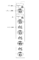
ここでは、液晶表示装置42の補助表示について説明する。即ち、まず、補助教示制御手段は、スタートレバー44が操作され、1遊技回の遊技が開始される毎に、液晶表示装置42での識別情報の変動表示を開始される。液晶表示装置42では、例えば図8に示すように、複数の疑似図柄列が表示される。本実施の形態では、これらの疑似図柄列として左疑似図柄列、中疑似図柄列及び右疑似図柄列の3つの疑似図柄列が表示されるが、それ以外の数の疑似図柄列が表示されてもよい。各疑似図柄列は、基本的には、複数種類の疑似図柄によって構成されている。各疑似図柄は、基本的には皿に盛られたタコ等の絵等によって構成されている。これらの疑似図柄は、前記回転体31,32,33のベルト36に付された図柄に基本的には対応している。すなわち、「7」図柄は、図8(a)の中央に表示されている「女の子+七」の疑似図柄に対応しており、「リプレイ」図柄は図8(a)の中央奥に表示されている「湯飲み茶碗」の疑似図柄に対応しており、「タコ」図柄(小役図柄)は、図8(a)の左右図柄列に表示されている「タコ」の疑似図柄に対応している。
【0103】
各々の疑似図柄列においては、あたかも回転寿司店における複数の(3つの)回転テーブル上に載置されたように表示される疑似図柄が、テーブルとともに回転(移動)可能に表示される。
【0104】
そして、疑似図柄の変動開始後、基本的には、第1番目のストップスイッチ45,46,又は47が押圧されたタイミングで、疑似図柄の変動が、左疑似図柄列、右疑似図柄列、中疑似図柄列の順で停止させられる。
【0105】
補助教示制御手段は、かかる表示演出を行いうる液晶表示装置42において、少なくとも、小役フラグ、リプレイフラグ、或いは、ビッグボーナスフラグの成立を報知する「ナビゲーション表示」や、ビッグボーナスフラグの成立時に小役フラグ等の成立と思わせる報知を行う「ナビゲーション外れ表示」や、種々の演出表示を行わせたりするべく、当該液晶表示装置42を表示制御する。なお、ナビゲーション表示とナビゲーション外れ表示とは、当該液晶表示装置42の表示内容のみから区別することはできない場合があり、この場合には、各回転体31,32,33の停止内容との関係から理解されるものである。
【0106】
即ち、補助教示制御手段は、「ナビゲーション表示」として、小役フラグ、或いはリプレイフラグ成立時には、そのゲームの終了前迄にフラグ成立に該当する小役、リプレイ、「7」に対応する疑似図柄を液晶表示装置42に表示停止させ、遊技者に表示された図柄を停止させるように促したり、遊技者に各フラグが成立している旨を教示したり、逆にフラグが成立していない旨を教示したりするべくナビゲーション的な機能を発揮させる。
【0107】
例えば、スタートレバー44が操作されたタイミング以降、液晶表示装置42では、疑似図柄の変動表示が開始される。そして、第1番目のストップスイッチ45,46,又は47が押圧されたタイミングで、主基板71から送信された情報に基づき、疑似図柄を順次停止させる。このとき、例えば、いずれの当りフラグも成立していない場合、つまり外れ時には、図8(a)に示すように、左、中、右疑似図柄列で全てが同一ではない疑似図柄を停止させる。また、例えば、小役フラグが成立している場合には、図8(b)に示すように、左、中、右疑似図柄列において「タコ」図柄に対応する「タコ」の疑似図柄をゾロ目で停止させる。さらに、例えば、リプレイフラグが成立している場合には、図示しないが、左、中、右疑似図柄列において「リプレイ」図柄に対応する「湯飲み茶碗」の疑似図柄をゾロ目で停止させる。
【0108】
また、例えばビッグボーナスフラグが成立している場合には、上記「ナビゲーション表示」、「ナビゲーション外れ表示」、「特殊演出表示」、「リーチ演出表示」のうちいずれかを実行する。ここで、「ナビゲーション表示」が行われる場合には、例えば図9(a)に示すように、第1番目のストップスイッチ45,46,又は47が押圧されたタイミングで、左、中、右疑似図柄列において「7」図柄に対応する「女の子+七」の疑似図柄をゾロ目で停止させる。
【0109】
次に「ナビゲーション外れ表示」について説明する。「ナビゲーション外れ表示」が行われる場合、本来フラグの成立していない小役或いはリプレイ図柄に対応する疑似図柄をそのゲームの終了前迄に液晶表示部42に表示させ、同じく遊技者に表示された図柄を停止させるように促すナビゲーション的な機能を発揮させるが、それら表示された図柄は本来フラグ成立していないのであるから実際にはその表示された図柄が有効ライン上に揃うことはない点で上記ナビゲーション表示とは意味内容が異なる。そして、このように、液晶表示装置42上では疑似図柄が揃ったにもかかわらず、有効ライン上に図柄が揃わないことに気づいた遊技者は、「ナビゲーション外れ表示」が行われたこと、つまり、ビッグボーナスゲームフラグが成立していることを察知することができる。
【0110】
また、ビッグボーナスフラグが成立している場合には、「特殊演出表示」が行われることもある。この場合、図9(b)に示すように、第1番目のストップスイッチ45,46,又は47が押圧されたタイミングで、左、右疑似図柄列において「7」図柄に対応する「女の子+七」の疑似図柄をゾロ目で停止させ、しばらく間をおいて中疑似図柄列において、「魚」をモチーフにした特殊疑似図柄を停止表示させる。この特殊疑似図柄は通常は表示されない類のものであるため、当該停止表示によって、遊技者は、ビッグボーナスゲームフラグが成立していることを察知することができる。
【0111】
さらに、ビッグボーナスフラグが成立している場合には、「リーチ演出表示」が行われることもある。この場合、図10(a)に示すように、第1番目のストップスイッチ45,46,又は47が押圧されたタイミングで、左、右疑似図柄列において「7」図柄に対応する「女の子+七」の疑似図柄をゾロ目で停止させ、しばらく間をおいて、別の演出画面を表示させる。例えば、図10(b)に示すように、まず中疑似図柄列の疑似図柄に関し、その表示領域を上方へ移動させる。また、表示部上に人物キャラクタ、猫及び盆を表示する。これとともに、上方へ表示領域の移動した疑似図柄を盆の上に載置されているかの如く表示する。そして、人物キャラクタ及び猫があたかも盆を引っ張りあうように左右方向に動作させるとともに、疑似図柄を左右方向に交互にスライドさせつつ変形表示する。また、この変形表示に伴って、疑似図柄を適宜切換変動させる。このように、猫及び人物キャラクタがあたかも盆を引っ張りあう動作に連動し、盆の上に載置表示された疑似図柄が左右方向に交互にスライドさせつつ変形切換表示され、かかる動作が連続して繰り替えされ、その後「女の子+七」の疑似図柄で停止表示される。もちろん、小役フラグが成立している場合等(ビッグボーナスフラグが成立していない場合)においても、上記のようなリーチ演出表示を行うこととしてもよい。この場合、最後に中疑似図柄列において停止表示される疑似図柄は、「女の子+七」の疑似図柄以外の疑似図柄となる。
【0112】
また、前記補助教示制御手段により、遊技球の投入動作中のタイムラグ、即ち遊技球の投入操作が行われてからスタートレバー44の操作に基づいて回転体31,32,33の回転が開始されるまでのタイムラグ(待ち時間)を利用して、液晶表示部42に各種表示(情報付与)を行わせるように表示制御することとしてもよい。このような演出表示を行うことで、遊技球の取込に要する期間を無駄にすることなく遊技者の興趣低下を抑制することができる。
【0113】
次に、以上の構成からなる遊技機1の作用につき、遊技方法を踏まえて説明する。
【0114】
遊技の開始に際し、遊技者は、クレジットが所定数以上あるか又は遊技球が上受皿12に所定個数あることを条件に、ベットスイッチ51,52,53を押圧操作することにより貯留記憶に基づく仮想遊技球又は実際の遊技球を投入する。該投入は、各ベット検出センサ85,86,87によって検出され、その検出信号を受けて主基板71は遊技球(仮想遊技球を含む)の投入があったことを判断する。このとき、クレジットモード時であれば、貯留記憶されていた仮想遊技球が投入されることとなる。例えば、クレジットモード時において、15個以上の貯留数(クレジット数)がある場合において、マックスベットスイッチ53が押圧操作されたような場合には、残数表示部56における残数表示数を「15」だけ減じて表示するとともに、前記記憶手段は、「15」だけ減じた数を貯留記憶数として記憶する。これに対し、貯留数(クレジット数)が15個未満しかない場合において、マックスベットスイッチ53が押圧操作された場合、或いは貯留数(クレジット数)が5個未満しかない場合において、1ベットスイッチ51が押圧操作されたような場合には、当該押圧操作は無効化される。
【0115】
また、ダイレクトモード時であれば、上受皿12にある実際の遊技球が取込まれ投入されることとなる。例えばダイレクトモード時において、15個以上の遊技球が上受皿12にある場合において、マックスベットスイッチ53が押圧操作されたような場合には、上受皿12上の15個の遊技球が上記取込装置4によって取込まれ、5個以上の遊技球が上受皿12にある場合において、1ベットスイッチ51が押圧操作されたような場合には、上受皿12上の5個の遊技球が上記取込装置4によって取込まれる。これに対し、遊技球が15個未満しかない場合においてマックスベットスイッチ53が押圧操作された場合、或いは5個未満しかない場合において1ベットスイッチ51が押圧操作された場合には、当該押圧操作は無効化される。
【0116】
このときの遊技球投入数(=ベット数×5)に応じて主基板71はベット数表示部43をセグメント表示させる。ここで、1ベットスイッチ51の1回の押圧操作(5個の遊技球の投入)であればベット数表示部43には「1」が表示されて下ラインのみが有効化される。また、1ベットスイッチ51の2回の押圧操作、又は2ベットスイッチ52の1回の押圧操作(10個の遊技球の投入)であればベット数表示部43には「2」が表示されて上下ラインが有効化される。さらに、マックスベットスイッチ53の押圧操作等(15個の遊技球の投入)であればベット数表示部43には「3」が表示されて上下ライン及び山谷ラインが有効化される。なお、本実施の形態では、ベット数表示部43においてベット数、つまり有効ラインを表示することとしているが、これに代えて、或いはこれに加えて、有効ラインに対応する有効ライン表示ランプ等を設け、どのラインが有効化されているのかをより明示的に表示することとしてもよい。
【0117】
なお、クレジットモード下でのベットスイッチ51,52,53の操作による仮想遊技球投入の場合には、主基板71はクレジットされている遊技球の貯留記憶数をその分減算し、その減算値に応じた表示を残数表示部56に行わせるように表示制御する。また、ダイレクトモード下でのベットスイッチ51,52,53の操作による遊技球投入の場合には、主基板71は取込装置4にその旨の信号を出力し、その分の遊技球を上受皿12から取込むよう取込装置4を駆動制御する。
【0118】
少なくとも1ラインが有効化されている時点で、遊技者がスタートレバー44を操作すると、その操作がスタート検出センサ81によって検出され、その検出信号を受けて主基板71はスタートレバー44の操作があったことを判断する。また、これとともに、その旨の情報をサブ基板72へと送信する。そして、主基板71は、全ての回転体31,32,33(ベルト36)を一斉(同時でもよいし所定の時間差を設けてもよい。)に回転させるべく、モータ37,38,39を駆動制御する。その結果、各ベルト36は、遊技者にとっては表面に付された図柄を目視することが困難な程度の速度で一方向に回転し、各表示窓21,22,23を介して各図柄が上から下へ向かって可変表示されているよう映し出される。
【0119】
なお、このタイミングにおいて、サブ基板72(補助教示制御手段)は、上述したように液晶表示装置42における補助表示等を開始させる。
【0120】
また、前記スタートレバー44の操作に基づく検出信号が主基板71に入力されたタイミングで、通常遊技中では、小役抽選手段、リプレイゲーム抽選手段、ビッグボーナス抽選手段による各抽選が行われる。
【0121】
小役抽選手段による抽選結果が、小役フラグ成立を意味する場合は、適宜の小役図柄を有効ライン上に停止させ得る権利がそのゲームにおいてのみ与えられる。また、リプレイゲーム抽選手段による抽選結果が、リプレイフラグ成立を意味する場合は、リプレイゲームへ移行する権利がそのゲームにおいてのみ与えられる。また、ビッグボーナス抽選手段による抽選結果がビッグボーナスフラグ成立を意味する場合は、ビッグボーナスゲームへ移行する権利が与えられ、そのフラグはビッグボーナスゲームへ移行するまで保持される。さらに、各抽選手段の抽選結果が、いずれの条件成立をも意味しない場合には、いずれのフラグもたたない。
【0122】
以上の各抽選手段による抽選が終了した後、遊技者がストップスイッチ45,46,47を任意の順序で操作すると、その操作がそれぞれストップ検出センサ82,83,84によって個別に検出され、各検出信号を受けて主基板71は各ストップスイッチ45,46,47の操作があったことを判断する。すると、主基板71は、操作された各ストップスイッチ45,46,47に対応した回転体31,32,33を個別に停止させるべく、各モータ37,38,39を停止制御する。
【0123】
これら各回転体31,32,33(ベルト36)の停止位置は、上記各抽選手段による抽選結果である各成立フラグに基づき、主基板71の記憶手段に記憶されている前記各テーブルを参照して決定される。このとき、有効ラインから回転体回転方向手前の4図柄分までに成立フラグに対応した図柄が存在すれば、原則として、その図柄が積極的に有効ライン上に引き込まれるような制御がなされることとなり、回転体停止タイミングが4図柄分手前までの誤差であれば、その誤差を吸収することができる。その結果、遊技者が熟練していなくとも主基板71によって成立フラグに応じた図柄を有効ライン上に極力停止させることが可能となる。また、上下一対の2つの図柄が組合わさることによって「7」等の絵、模様、数字等が構成されるようになっているが、これらは、それぞれ異なる図柄であることは既に説明したが、本実施の形態では、異種の図柄同士が上下に停止表示されることがないよう引き込み制御が行われるようになっている。例えば、一の表示窓21,22又は23に対応して、上段に「7」の数字の下半分の「7」図柄が停止され、下段に「リプレイ」の上半分の「リプレイ」図柄が停止されることがないよう、つまり、同種の図柄同士が上下に停止表示されるよう、引き込み制御が行われる。
【0124】
なお、所定のタイミング(例えば第1番目のストップスイッチ45,46,又は47が押圧されたタイミング)において、サブ基板72(補助教示制御手段)は、上述したように液晶表示装置42におけるリーチ演出表示等を実行する。
【0125】
各回転体31,32,33の停止時において、有効ライン上の停止図柄の組合せが、予め定められた所定の図柄の組合せである場合、即ち小役図柄の組合せ、リプレイ図柄の組合せ、ビッグボーナス図柄の組合せである場合、主基板71は各停止図柄の組合せに応じて払い出される遊技球数を獲得数表示部57に表示させる。
【0126】
主基板71は、獲得数表示部57への表示と並行して、各停止図柄の組合せに応じた数の遊技球を遊技価値として払い出すための払出制御を行う。かかる遊技球の払出は、原則として主基板71が電源基板73を介して払出装置9を駆動制御することにより、上受皿12等へ直接的に現実の遊技球として払い出される。ただし、切換スイッチ54の操作を切換検出センサ88が検出し、主基板71がクレジットモードであると判断した場合においては、貯留記憶できる最大値(250個分)に達していない場合には、その分が直接払出装置9を駆動することなく、クレジット遊技球(仮想遊技球)として貯留記憶される。この場合、主基板71はクレジットされている遊技球の貯留記憶数に今回獲得した遊技球数分を加算し、その加算値に応じた表示を残数表示部56に行わせるように表示制御する。勿論、この場合でも貯留記憶できる最大値である250個分を越えた分は払出装置9より直接遊技球が払い出される。
【0127】
そして、有効ライン上に揃った図柄が小役図柄或いは何ら払出のない図柄の組合せである場合には、通常遊技が続行される。一方、有効ライン上に揃った図柄の組合せがリプレイ図柄の組合せである場合にはリプレイゲーム制御手段によって次回のゲームを無償で行うことができるリプレイゲームが実行される。また、有効ライン上に揃った図柄の組合せがビッグボーナス図柄の組合せである場合にはビッグボーナス制御手段によってビッグボーナスゲームが実行される。ここで、本実施の形態の遊技機1では、ビッグボーナスゲームの終了条件として、所定回の遊技(30ゲームの終了又は3回のジャックインゲームの終了)の他、払出遊技球数が上限値(具体的には2250個)に達したか否かという条件も含まれるように構成されている。従って、30ゲーム又は3回のジャックインゲームの終了を待たずして払出遊技球数が上限値である2250個に達すると、そこでビッグボーナスゲームが終了されるようにして、必要以上に射幸性をあおらないようにしている。
【0128】
なお、小役図柄、リプレイ図柄、ビッグボーナス図柄等が有効ライン上に揃った場合、サブ基板72は、各ランプ表示部62,63,64等を表示制御して小役成立や、リプレイゲームへの移行や、ボーナスゲーム成立を表示報知するとともに、スピーカ61を適宜駆動制御して音声報知する。なお、これらスピーカ61による音声報知は、遊技者への遊技価値返還による利益が大きいもの程大袈裟なもの(音量を大きくしたり、トーンを高くしたり、リズムを変化させる等)とすることが好ましい。各報知部の表示態様についても同様であり、例えばビッグボーナスゲームではめまぐるしく点滅させる等のように表示態様を変化させることによって、得られる利益の大きさを遊技者に推し量らせることができる。
【0129】
さて、本実施の形態の遊技機1は、上述のとおり、回転体31,32,33に関し、ベルト36を用いて扁平状に周回させることとしている。このため、断面円形のリールによって図柄変動領域を形成する場合に比べて、遊技機1の厚みを抑えることができる。
【0130】
一方で、ベルト36を扁平状に周回させることとした場合、視認される図柄の変動態様が平面的になってしまうことが懸念される。この点、本実施の形態では、ベルト36のうち表示窓21,22,23から視認される部分については表示窓21,22,23側に凸となるように構成したことから、遊技機1の厚みを抑えつつも、遊技者がベルト36回転中の図柄を目で追い易くなる。特に、ベルト36の表示窓21,22,23側への凸形状は、円弧状に凸となる形状であるため、ベルト36の変形による疲労が軽減されるとともに、ベルト36回転時の図柄の可変表示が滑らかなものとなって違和感をなくすことができる。
【0131】
また、本実施の形態では、視認部分に対応する従動ローラ35寄りに、押えローラ41を設けることとしており、これにより、表示窓21,22,23から見えるベルト36に十分な奥行き感を生ぜしめることができ、遊技者がベルト36回転中の図柄を一層目で追い易くなる。
【0132】
さらに、本実施の形態では、ベルト36の扁平方向に沿って、平板状の液晶表示装置42を配置し、その表示部を補助表示窓24から視認可能としている。このため、遊技機1の厚みを増加させることなく、結果として表示装置ユニット30のコンパクト化を図ることができる。
【0133】
尚、上記実施の形態の記載内容に限定されず、例えば次のように実施してもよい。
【0134】
(a)上記実施の形態では、ベルト36のうち表示窓21,22,23に臨む部分である従動ローラ35として比較的大径のものを採用している。このため、特に言及していないが、当該従動ローラ35内に蛍光ランプ等のバックライトを配置することも可能である。
【0135】
(b)各ローラとして、同径のものを用いた場合には、表示窓から視認される図柄の変動態様が平面的なものとなってしまいがちである。この点、上記実施の形態では、駆動ローラ34の径と従動ローラ35の径とをそれぞれ異ならせているため、たとえ押えローラ41を省略したとしても表示窓21,22,23から視認される図柄の変動態様が平面的なものとはならない。それ故、場合によっては前記押えローラ41を省略することも可能である。
【0136】
(c)逆に、押えローラ41を設ける場合には、同径のローラを採用することとしてもよい。
【0137】
(d)駆動ローラ34及び従動ローラ35の位置関係を上下逆にしてもよい。
【0138】
(e)駆動ローラ34及び従動ローラ35の径の大小関係を逆にしてもよい。
【0139】
(f)上述した各ローラ、すなわち、駆動ローラ34、従動ローラ35及び押えローラ41に代えて、左右一対のプーリ或いはギヤを採用することとしてもよい。すなわち、「各手段において、「ローラ」に代えて、「プーリ」或いは「ギヤ」としたこと」としても差し支えない。
【0140】
(g)上記実施の形態では、電気的表示手段として、液晶表示装置42を用いることとしているが、他の電気的表示手段、例えば、CRT、ドットマトリックス、LED、エレクトロルミネセンス(EL)、蛍光表示管等を用いてもよい。
【0141】
(h)上記実施の形態における図柄の種類、配列等はあくまでも一例にすぎず、例えば他の小役図柄を盛り込む等、任意の構成を採用することができる。また、絵、数字、文字等に限らず、幾何学的な線や図形等であってもよい。また、光や色等によって図柄を構成することも可能であるし、立体的形状等によっても図柄を構成し得るし、これらを複合したものであっても図柄を構成し得る。即ち、図柄は識別性を有した情報(識別情報)としての機能を有するものであればよい。
【0142】
(i)上記実施の形態におけるスタートレバー44等に代表される操作手段や、残数表示部56等に代表される表示手段の配置はあくまでも一例に過ぎず、例えばスタートレバー44を右側に配置したり、レバーに代えてボタンにする等、適宜変更することは何ら差し支えない。
【0143】
(j)全ての制御を主基板71により司られる構成としてもよい。つまり、サブ基板72を省略した構成を採用してもよい。
【0144】
(k)上記実施の形態ではビッグボーナスゲームを有する遊技機1について説明したが、一回のジャックインゲームからなるレギュラーボーナスゲームを行いうる遊技機に適用してもよい。また、逆にビッグボーナスゲームを省略したものとしてもよい。更に、ビッグボーナスゲーム後に所定条件成立(所定ゲーム回数の終了、所定フラグ成立等)までメダルの消費を抑えてゲームを進行し得るチャンスゲーム機能等の各種付加価値を設けたものとしてもよい。
【0145】
(l)上記実施の形態における遊技球の、1ベット当りの投入数(所定数)、最大投入数、払出個数等はあくまでも例示であって、上記数値に特に限定されるものではない。
【0146】
(m)上記実施の形態において説明した遊技機1の他、パチンコ機やアレンジボール機、スロットマシンに適用してもよいし、その他の遊技機に適用してもよい。
【図面の簡単な説明】
【図1】一実施の形態における遊技機の正面図である。
【図2】前面扉を開放した状態を示す正面図である。
【図3】各回転体のベルトの図柄配列を示す説明図である。
【図4】(a)は表示窓から視認される図柄の一例を示す正面図であり、(b)は表示窓と有効ラインの関係を模式的に示す正面図である。
【図5】表示装置ユニット等を模式的に示し示す側断面図である。
【図6】遊技機を示す背面図である。
【図7】主基板等の電気的構成を説明するためのブロック図である。
【図8】(a),(b)ともに液晶表示装置に表示される疑似図柄等を示す正面図である。
【図9】(a),(b)ともに液晶表示装置に表示される疑似図柄等を示す正面図である。
【図10】(a),(b)ともに液晶表示装置に表示される疑似図柄等を示す正面図である。
【符号の説明】
1…外枠、2…前面枠、3…前面扉、4…取込装置、9…払出装置、10…遊技機、11…払出装置、12…上受皿、13…下受皿、21,22,23…表示窓、24…補助表示窓、30…表示装置ユニット、31…左回転体、32…中回転体、33…右回転体、34…駆動ローラ、35…従動ローラ、36…ベルト、37,38,39…モータ、41…押えローラ、42…電気的表示装置を構成する液晶表示装置、44…スタートレバー、45,46,47…ストップスイッチ、71…主基板、72…サブ基板、73…電源基板。[0001]
BACKGROUND OF THE INVENTION
The present invention relates to a gaming machine.
[0002]
[Prior art]
As a kind of gaming machine, there is known a slot machine or the like provided with variable display means for displaying a stop symbol after variably displaying a symbol row formed by attaching a plurality of symbols to an annular reel surface. This type of gaming machine includes a predetermined game (special game) that is advantageous to a player, such as a big bonus game, for example, when a stop symbol displayed on an active line that is a predetermined area of a variable display means is a specific symbol. What happens) is provided. In such a slot machine, for example, medals are generally used as game media. That is, one to three medals are inserted for each game, and the start of a so-called game such as reel rotation is allowed by such insertion.
[0003]
There is also known a pachinko gaming machine provided with variable display means for displaying a stopped symbol after variably displaying a symbol row formed by attaching a plurality of symbols to the reel or belt surface. In this type of gaming machine, when a stop symbol displayed on an active line, which is a predetermined area of the variable display means, is a specific symbol, for example, a predetermined advantage advantageous to a player such as a jackpot that opens a big prize opening. A game (special game state) is generated.
[0004]
Further, in recent years, a gaming machine capable of playing a game like the above slot machine using a game ball used in a pachinko machine instead of a medal has been considered. In such a gaming machine, a variable display of variable display means is started by operating a lever after a predetermined number of game balls are taken in. Also, a lot of game balls are paid out when the special game state occurs. If such a gaming machine is used instead of a slot machine, gaming balls such as pachinko halls can handle gaming balls as a common gaming medium. Therefore, problems such as a burden on equipment due to separate handling of medals and game balls and restrictions on the location of game machines, which are often seen in current game halls in which pachinko machines and slot machines are mixed, can be solved.
[0005]
[Problems to be solved by the invention]
However, in the above various gaming machines, there is a disadvantage that the depth of the gaming machine is increased when an annular reel is used as the variable display means. In addition, the reel installation area of the annular reel is increased, and there is a problem that the installation area of other gaming machines, for example, an electric display device is reduced, or the display device cannot be installed at a position that is easily visible to the player.
[0006]
The present invention has been made in view of the above circumstances, and its main purpose is to reduce the thickness of the gaming machine to make it compact, or to reduce the occupation area of the variable display means for mechanically displaying the symbols variably. An object of the present invention is to provide a gaming machine that can secure an installation space for other gaming machines.
[0007]
In particular, in the type of gaming machine that can execute one game round after taking in a game ball, the depth of the gaming machine should be reduced because it is installed on the same island as the pachinko machine. One of the purposes is to prevent the game from being spoiled even if the depth of the gaming machine is reduced.
[0008]
[Means for solving the problems and effects thereof]
Means and the like effective for solving the above problems are shown below. In addition, an action, an effect, etc. are each described immediately after each means as needed.
[0009]
A gaming machine, wherein a portion of the endless belt that is visible from a display window is wound so as to protrude toward the display window in the rotation direction of the belt.
[0010]
By using an endless belt, the thickness of the gaming machine can be reduced as compared with the case where the symbol variation region is formed by a reel having a circular cross section (annular). However, when an endless belt is used, the variation of the symbols visually recognized from the display window becomes planar, making it difficult for the player to follow the symbols while the belt is rotating. In this regard, in this means, since the normal state of the endless belt is configured so that the portion visible from the display window is convex toward the display window side, the player is rotating the belt while suppressing the thickness of the gaming machine. It becomes easier to follow the design with your eyes.
[0011]
Mean 2. A gaming machine configured to circulate an endless belt with a pattern on its surface and provided with a display window so that a part of the endless belt can be visually recognized, and to be able to visually recognize the pattern from the display window In
A gaming machine characterized in that the endless belt circulates in a flat shape, and a portion of the endless belt that is visible from the display window is convex toward the display window in the rotation direction of the belt. .
[0012]
By using the endless belt to circulate in a flat shape, the thickness of the gaming machine can be suppressed as compared with the case where the symbol variation area is formed by a reel having a circular cross section. However, when the endless belt is circulated in a flat shape, the variation of the symbols visually recognized from the display window becomes planar, and it is difficult for the player to follow the symbols while the belt is rotating. In this regard, in this means, the portion of the endless belt that is visible from the display window is configured to be convex toward the display window, so that the player can rotate the belt while suppressing the thickness of the gaming machine. It becomes easier to follow the design with your eyes.
[0013]
In the
[0014]
Means 3. It is provided with a taking-in means for taking in a game ball, and when a predetermined number of game balls are taken in, the endless belt having a pattern on its surface can be rotated and stopped, and one endless belt can be executed. In a gaming machine in which a display window is provided so that a part of the display can be visually recognized and the symbol can be visually recognized from the display window.
A gaming machine characterized in that a portion of the endless belt that is visible from the display window is configured to protrude toward the display window in the rotation direction of the belt.
[0015]
By using the endless belt, the thickness of the gaming machine can be suppressed as compared with the case where the symbol variation region is formed by the reel having a circular cross section. However, when an endless belt is used, the variation of the symbols visually recognized from the display window becomes planar, making it difficult for the player to follow the symbols while the belt is rotating. In this regard, in this means, since the normal state of the endless belt is configured so that the portion visible from the display window is convex toward the display window side, the player is rotating the belt while suppressing the thickness of the gaming machine. It becomes easier to follow the design with your eyes.
[0016]
Means 4. It is provided with a taking-in means for taking in a game ball, and when a predetermined number of game balls are taken in, the endless belt having a pattern on its surface can be rotated and stopped, and one endless belt can be executed. In a gaming machine in which a display window is provided so that a part of the display can be visually recognized and the symbol can be visually recognized from the display window.
A gaming machine characterized in that the endless belt circulates in a flat shape, and a portion of the endless belt that is visible from the display window is convex toward the display window in the rotation direction of the belt. .
[0017]
By using the endless belt to circulate in a flat shape, the thickness of the gaming machine can be suppressed as compared with the case where the symbol variation area is formed by a reel having a circular cross section. However, when the endless belt is circulated in a flat shape, the variation of the symbols visually recognized from the display window becomes planar, and it is difficult for the player to follow the symbols while the belt is rotating. In this regard, in this means, the portion of the endless belt that is visible from the display window is configured to be convex toward the display window, so that the player can rotate the belt while suppressing the thickness of the gaming machine. It becomes easier to follow the design with your eyes.
[0018]
In the
[0019]
[0020]
According to the
[0021]
Means 6. In the
[0022]
According to the means 6, the endless belt, its driving system, and the electrical display device constitute a unit and are attached to the gaming machine main body as an integral unit, so that they are assembled as compared with the case where they are assembled separately. Is easy.
[0023]
Mean 7 It is provided with a taking-in means for taking in a game ball, and when a predetermined number of game balls are taken in, the endless belt having a pattern on its surface can be rotated and stopped, and one endless belt can be executed. In a gaming machine in which a display window is provided so that a part of the display can be visually recognized and the symbol can be visually recognized from the display window.
A gaming machine characterized in that the endless belt is stretched between a small-diameter roller and a large-diameter roller, and a portion spanned by the large-diameter roller of the endless belt is disposed corresponding to the display window.
[0024]
By hanging the endless belt between a pair of rollers, etc., the thickness of the gaming machine can be suppressed as compared with the case where the symbol variation area is formed by a reel having a circular cross section. However, when trying to reduce the thickness of the gaming machine using the same diameter roller as the endless belt, the pattern variation seen from the display window becomes planar, and for the player It becomes difficult to follow the pattern while the belt is rotating. In this regard, in this means, the region that is visually recognized from the display window is configured by the portion that is stretched over the large-diameter roller by using a roller having a different diameter as the roller over which the endless belt is stretched. While suppressing the thickness, it becomes easier for the player to follow the pattern while the belt is rotating.
[0025]
[0026]
According to the
[0027]
Means 9. A gaming machine according to
[0028]
According to the means 9, the electrical display device can be connected to the gaming machine without increasing the thickness of the gaming machine by disposing the electrical display device substantially in parallel in the space formed on the small-diameter roller side with respect to the presser roller. Can be arranged at the central position. In this case, it is preferable that the endless belt and the electric display device are arranged so as to fit in the rectangular parallelepiped space as a whole, whereby the display rendering devices can be made compact.
[0029]
[0030]
According to the
[0031]
[0032]
According to the
[0033]
Means 12. A gaming machine according to any one of
[0034]
According to the means 12, since the game value given to the player is determined according to the symbol stop situation, the interest of the game can be enhanced.
[0035]
[0036]
According to the
[0037]
[0038]
According to the
[0039]
[0040]
According to the
[0041]
Here, it is possible to specify such information, but in order to avoid boring the waiting state when there is a waiting time for taking in a game ball of several seconds, it is preferable to give a clue to obtain such information. . For example, when a predetermined game is progressed and the game is established, the player can know that a predetermined winning is made by an internal lottery.
[0042]
Means 16. In any one of
[0043]
According to the means 16, the game ball held in the ball receiving tray is supplied to the taking-in means by the inclination of the ball receiving surface of the ball receiving tray. Therefore, if the game balls are put in the ball tray, the game balls can be taken in one after another by the taking-in means.
[0044]
[0045]
According to the
[0046]
Means 18. A gaming machine characterized in that in the combination of means 16 and means 17, the payout means is configured to pay out the game ball to the ball receiving tray, particularly to the upstream side of the inclination of the ball receiving tray.
[0047]
According to the means 18, the game ball from the payout means is received by the ball receiving tray, and the game ball is taken into the taking-in means by tilting, so that the player actively takes the game ball to the ball receiving tray. Has the advantage of being reduced.
[0048]
Means 19. In the
[0049]
According to the means 19, the display area of the belt which is a variable display means is formed in a part of the game area, the installation area of the display window is small, and the pachinko machine is installed in the island facility of the hall. However, this means has the advantage that the number of symbols can be increased without reducing the size of the symbols while reducing the belt occupation area.
[0050]
DETAILED DESCRIPTION OF THE INVENTION
Hereinafter, an embodiment in which a gaming machine in which a game is started after taking in a game ball will be described with reference to the drawings.
[0051]
Note that the gaming machine according to the present embodiment has properties similar to a so-called slot machine with respect to basic game contents. However, a game requires a game ball (a game ball similar to a pachinko machine: a pachinko ball) as a predetermined number of game media (game value), and if a predetermined condition is satisfied, a plurality of game balls, A large amount of game balls are arranged to be paid out.
[0052]
As shown in FIG. 1, the
[0053]
A
[0054]
As described above, the
[0055]
As shown in FIGS. 1 and 2, an upper tray 12 capable of storing game balls on the player side is detachably attached to the lower portion of the
[0056]
Then, when the throwing operation is performed, the take-in device 4 is actuated so that a predetermined number of game balls in the upper tray 12 are taken in from the right side of the figure. In addition, when a predetermined condition is satisfied, the payout device 9 is operated, whereby the game balls stored in the tank 6 are basically paid out to the upper tray 12 via the
[0057]
Below the upper tray 12, a
[0058]
In the portion corresponding to the upper tray 12, the bulging portion of the
[0059]
On the
[0060]
As shown in FIGS. 2 and 5, a
[0061]
The driving
[0062]
Above each driven
[0063]
Specifically, due to the presence of the
[0064]
Further, a substantially flat liquid
[0065]
Now, when the
[0066]
Next, the symbols attached to the
[0067]
As a symbol, for example, there is a “7” symbol (the two symbols above) for shifting to a big bonus game (big bonus symbol). In addition, there are “replay” symbols (for example, the third and fourth from the top) for shifting to the replay game. In addition, there is an “octopus” symbol (for example, the ninth and tenth from the top) as a small character symbol from which a small character is paid out. In the present embodiment, the number of symbols in each
[0068]
With respect to the small role symbol, when the “octopus” symbol is aligned with the left, middle, and right on the effective line described later, 75 game balls are paid out, and “7”, which is a combination of big bonus symbols. When the symbols are aligned with the left, middle, and right on the active line, 75 game balls are paid out. Further, when the “replay” symbols are aligned with the left, middle and right on the active line, the game balls are not paid out. In this embodiment, a further combination of small symbols is set. That is, (1) “7” symbol, “7” symbol, “Replay” symbol, (2) “7” symbol, “7” symbol, “octopus” symbol in the order of left, middle and right on the active line. (3) “7” symbol, “Replay” symbol, “7” symbol, (4) “7” symbol, “octopus” symbol, “7” symbol, (5) “Replay” symbol, “7 The symbols “7”, “7”, and (6) “Octopus”, “7”, and “7” symbols are arranged, and 75 game balls are paid out.
[0069]
As shown in FIGS. 4A and 4B, the
[0070]
In the bet
[0071]
As shown in FIG. 1, on the left side of the
[0072]
In addition, a button-like bet switch that constitutes an input means for inserting a game ball is provided in the
[0073]
Further, the 2-
[0074]
Further, the max bet switch 53 is provided so that a plurality of (three) pressing operations such as the one betting
[0075]
Further, in the present embodiment, when the upper and lower lines and the Yamatani line (4 lines in total) are activated (15 game balls are inserted), the maximum bet (3 bets) is entered. That is, for example, or when the maximum bet switch 53 is pressed once, no further insertion is performed. Accordingly, in the present embodiment, when the maximum bet (3 bets) state is reached and the bet switches 51, 52, 53 are further pressed, the operation is invalidated.
[0076]
Further, in the
[0077]
That is, for example, when power is turned on, excess game balls up to a predetermined maximum value (for example, 250 game balls: maximum memory number) are stored and stored as credits (virtual game balls: stored game media) and paid out. “Credit mode” is set so that the played game balls are stored and stored as credits (virtual game balls). When the
[0078]
The
[0079]
Further, the
[0080]
By the way, in the present embodiment, as described above, the maximum storage number in the credit mode is set to, for example, “250” (corresponding to 50 bets). The remaining
[0081]
Note that various notifying parts (not shown) such as a big notifying part, a replay notifying part, and a small role notifying part are provided on the upper part of the gaming machine 1 (front door 3). These various notification units may be provided in places other than the upper part of the
[0082]
Further,
[0083]
As shown in FIGS. 6 and 7, the back set
[0084]
FIG. 7 is a block diagram illustrating the electrical configuration of the
[0085]
On the input side of the
[0086]
The payout device 9 is connected to the output side of the
[0087]
Further, a
[0088]
As described above, the
[0089]
The
[0090]
The
[0091]
The
[0092]
The
[0093]
The
[0094]
The
[0095]
The
[0096]
Further, the big bonus control means semi-forcibly pulls in and stops the rotation of each of the
[0097]
Here, the predetermined bonus game will be described. When execution of a predetermined bonus game is started (jacked in), a transition is made from a normal gaming state, which is the current gaming state, to a special state with a predetermined number of games (here, 12 times) as an upper limit. And then returned to the original gaming state. During the predetermined bonus game, there is only one active line (lower line). During the predetermined bonus game, a predetermined symbol (in this case, a replay symbol) is drawn by the timing at which the detection signal from the
[0098]
Here, the big bonus game can be jacked in up to a predetermined number of times (for example, 3 times) within the predetermined number of games (30 times), and the number of games during the jack-in during the big bonus game is It is not added to 30 times. Then, the big bonus control means is configured to end the predetermined bonus game by the third jack-in when the predetermined bonus game is completed the predetermined number of times (three times) even within the predetermined number of games (30 times). Forcibly end the big bonus game.
[0099]
The
[0100]
The various tables stored in the storage means (here, ROM but may be RAM) are individually set according to various established flags. Specifically, for example, when no flag is established, a “out-of-table” that prevents any symbol from being aligned on the active line, a predetermined small role symbol corresponding to the small role flag is valid “Position formation table” for aligning on the line, “Replay establishment table” for aligning the replay symbol on the effective line corresponding to the replay flag, and “7” symbol corresponding to the big bonus flag on the effective line In addition to a “big formation table” for aligning, the “line table” for determining on which effective line the above formation symbols are aligned. The storage unit also stores the number of virtual game balls in the credit mode.
[0101]
Further, the sub-board 72 includes “auxiliary teaching control means”. The auxiliary teaching control means mainly controls display of the liquid
[0102]
Here, auxiliary display of the liquid
[0103]
In each pseudo-symbol row, pseudo-symbols displayed as if they were placed on a plurality of (three) rotating tables in a sushi restaurant are displayed so as to be rotatable (movable) together with the table.
[0104]
After the pseudo symbol variation starts, basically, at the timing when the
[0105]
In the liquid
[0106]
That is, the auxiliary teaching control means, as “navigation display”, when the small role flag or replay flag is established, the small symbol corresponding to the flag establishment, replay, and the pseudo symbol corresponding to “7” before the end of the game. The display is stopped on the liquid
[0107]
For example, after the timing at which the
[0108]
For example, when the big bonus flag is established, any one of the “navigation display”, “navigation outage display”, “special effect display”, and “reach effect display” is executed. Here, when “navigation display” is performed, for example, as shown in FIG. 9A, the left, middle, and right pseudo-simulations are performed at the timing when the
[0109]
Next, “navigation off display” will be described. When “navigation off display” is performed, a pseudo symbol corresponding to a small role or a replay symbol for which a flag is not originally established is displayed on the liquid
[0110]
Further, when the big bonus flag is established, “special effect display” may be performed. In this case, as shown in FIG. 9B, at the timing when the
[0111]
Furthermore, when the big bonus flag is established, “reach effect display” may be performed. In this case, as shown in FIG. 10A, at the timing when the
[0112]
Further, the auxiliary teaching control means starts the rotation of the
[0113]
Next, the operation of the
[0114]
At the start of the game, the player performs virtual operation based on the stored memory by pressing the bet switches 51, 52, and 53 on condition that there are a predetermined number of credits or a predetermined number of game balls in the upper tray 12. A game ball or an actual game ball is inserted. The insertion is detected by each of the
[0115]
In the direct mode, an actual game ball in the upper tray 12 is taken in and thrown in. For example, in the direct mode, when there are 15 or more game balls in the upper tray 12 and the max bet switch 53 is pressed, 15 game balls on the upper tray 12 are taken in. When five or more game balls are taken in by the device 4 and are in the upper tray 12 and the 1-
[0116]
The
[0117]
In the case of inserting virtual game balls by operating the bet switches 51, 52, and 53 in the credit mode, the
[0118]
When the player operates the
[0119]
At this timing, the sub board 72 (auxiliary teaching control means) starts auxiliary display or the like on the liquid
[0120]
Further, at the timing when the detection signal based on the operation of the
[0121]
When the lottery result by the small role lottery means that the small role flag is established, the right to stop an appropriate small role symbol on the active line is given only in the game. Further, when the lottery result by the replay game lottery means that the replay flag is established, the right to shift to the replay game is given only in that game. If the lottery result by the big bonus lottery means that the big bonus flag is established, the right to shift to the big bonus game is given, and the flag is held until the shift to the big bonus game. Furthermore, when the lottery result of each lottery means does not mean that any condition is satisfied, no flag is set.
[0122]
When the player operates the stop switches 45, 46, and 47 in an arbitrary order after the lottery by each of the above lottery means is completed, the operations are individually detected by the
[0123]
The stop positions of the
[0124]
At a predetermined timing (for example, when the
[0125]
When each of the
[0126]
The
[0127]
When the symbols arranged on the active line are a combination of small symbols or symbols that are not paid out, the normal game is continued. On the other hand, when the combination of symbols arranged on the active line is a combination of replay symbols, a replay game that allows the next game to be performed free of charge is executed by the replay game control means. Further, when the combination of symbols arranged on the active line is a combination of big bonus symbols, the big bonus game is executed by the big bonus control means. Here, in the
[0128]
When the small role symbol, the replay symbol, the big bonus symbol, etc. are aligned on the active line, the sub-board 72 controls the display of the
[0129]
Now, as described above, the
[0130]
On the other hand, when the
[0131]
Further, in the present embodiment, the
[0132]
Further, in the present embodiment, a flat liquid
[0133]
In addition, it is not limited to the description content of the said embodiment, For example, you may implement as follows.
[0134]
(A) In the above-described embodiment, the driven
[0135]
(B) When rollers having the same diameter are used as the rollers, the pattern variation pattern visually recognized from the display window tends to be flat. In this respect, in the above embodiment, the diameter of the driving
[0136]
(C) Conversely, when the
[0137]
(D) The positional relationship between the driving
[0138]
(E) The magnitude relationship between the diameters of the driving
[0139]
(F) Instead of the above-described rollers, that is, the driving
[0140]
(G) In the above embodiment, the liquid
[0141]
(H) The types, arrangements, and the like of the symbols in the above embodiment are merely examples, and any configuration can be employed, for example, including other small role symbols. Moreover, not only a picture, a number, a character, etc. but a geometric line, a figure, etc. may be sufficient. In addition, the design can be configured by light, color, or the like, the design can be configured by a three-dimensional shape or the like, and the design can be configured by combining these. That is, it is sufficient that the symbol has a function as identification information (identification information).
[0142]
(I) The arrangement of the operation means represented by the
[0143]
(J) A configuration may be adopted in which all control is controlled by the
[0144]
(K) Although the
[0145]
(L) The number of games balls inserted per bet (predetermined number), the maximum number of games inserted, the number of payouts, etc. of the game balls in the above embodiment are merely examples, and are not particularly limited to the above numerical values.
[0146]
(M) In addition to the
[Brief description of the drawings]
FIG. 1 is a front view of a gaming machine according to an embodiment.
FIG. 2 is a front view showing a state in which a front door is opened.
FIG. 3 is an explanatory diagram showing a symbol arrangement of a belt of each rotating body.
4A is a front view showing an example of a symbol visually recognized from a display window, and FIG. 4B is a front view schematically showing a relationship between the display window and effective lines.
FIG. 5 is a side sectional view schematically showing a display device unit and the like.
FIG. 6 is a rear view showing the gaming machine.
FIG. 7 is a block diagram for explaining an electrical configuration of a main substrate and the like.
FIGS. 8A and 8B are front views showing pseudo symbols and the like displayed on the liquid crystal display device.
FIGS. 9A and 9B are front views showing pseudo symbols and the like displayed on the liquid crystal display device.
10 (a) and 10 (b) are front views showing pseudo symbols and the like displayed on the liquid crystal display device.
[Explanation of symbols]
DESCRIPTION OF
Claims (3)
前記無端状ベルトを上下に配設された第1回転体及び第2回転体の外周側に掛け渡すことにより、前記無端状ベルトを上下方向に延びる偏平状に周回させるものとし、
前記無端状ベルトをその外周側かつ手前側から前記第1回転体に向けて押える押え体を設けることにより、前記無端状ベルトの前記第1回転体に沿った領域を拡張して前記押え体よりも手前側を前方に凸となるように周回させるものとし、
当該凸となった部分に現れる図柄を前記表示窓から視認可能とし、
前記押え体よりも前記第2回転体側となる前記無端状ベルトの前方領域に、遊技者に所定のタイミングで情報を付与する情報付与手段を設けたことを特徴とする遊技機。A gaming machine configured to circulate an endless belt with a pattern on its surface and provided with a display window so that a part of the endless belt can be visually recognized, and to be able to visually recognize the pattern from the display window In
By wrapping the endless belt on the outer peripheral side of the first rotating body and the second rotating body arranged vertically, the endless belt is rotated in a flat shape extending in the vertical direction,
By providing a pressing body for pressing the endless belt from the outer peripheral side and the front side thereof toward the first rotating body, an area along the first rotating body of the endless belt is expanded to extend from the pressing body . And the front side will circulate so that it is convex forward,
The symbol appearing on the convex part is visible from the display window,
A gaming machine, characterized in that information giving means for giving information to a player at a predetermined timing is provided in a front area of the endless belt that is closer to the second rotating body than the presser.
Priority Applications (1)
| Application Number | Priority Date | Filing Date | Title |
|---|---|---|---|
| JP2002181884A JP4352369B2 (en) | 2002-06-21 | 2002-06-21 | Game machine |
Applications Claiming Priority (1)
| Application Number | Priority Date | Filing Date | Title |
|---|---|---|---|
| JP2002181884A JP4352369B2 (en) | 2002-06-21 | 2002-06-21 | Game machine |
Publications (3)
| Publication Number | Publication Date |
|---|---|
| JP2004024338A JP2004024338A (en) | 2004-01-29 |
| JP2004024338A5 JP2004024338A5 (en) | 2005-10-20 |
| JP4352369B2 true JP4352369B2 (en) | 2009-10-28 |
Family
ID=31178606
Family Applications (1)
| Application Number | Title | Priority Date | Filing Date |
|---|---|---|---|
| JP2002181884A Expired - Fee Related JP4352369B2 (en) | 2002-06-21 | 2002-06-21 | Game machine |
Country Status (1)
| Country | Link |
|---|---|
| JP (1) | JP4352369B2 (en) |
-
2002
- 2002-06-21 JP JP2002181884A patent/JP4352369B2/en not_active Expired - Fee Related
Also Published As
| Publication number | Publication date |
|---|---|
| JP2004024338A (en) | 2004-01-29 |
Similar Documents
| Publication | Publication Date | Title |
|---|---|---|
| JP2008131985A (en) | Game machine | |
| JP2002282421A (en) | Game machine | |
| JP2001346935A (en) | Game stand | |
| JP4337083B2 (en) | Game machine | |
| JP4352408B2 (en) | Game machine | |
| JP4647181B2 (en) | Game machine | |
| JP4352369B2 (en) | Game machine | |
| JP3815397B2 (en) | Game machine | |
| JP3815389B2 (en) | Game machine | |
| JP4352370B2 (en) | Game machine | |
| JP3990305B2 (en) | Amusement stand | |
| JP2004229690A (en) | Game machine | |
| JP2007289484A (en) | Game machine | |
| JP2004065406A (en) | Game machine | |
| JP2005177528A (en) | Game machine | |
| JP2005261986A (en) | Game machine | |
| JP2004105757A (en) | Game machine | |
| JP2005230179A (en) | Slot machine | |
| JP4697319B2 (en) | Game machine | |
| JP2010253025A (en) | Slot machine | |
| JP2004105758A (en) | Game machine | |
| JP2008253384A (en) | Game machine | |
| JP2005118487A (en) | Game machine | |
| JP5368159B2 (en) | Slot machine | |
| JP5035406B2 (en) | Game machine |
Legal Events
| Date | Code | Title | Description |
|---|---|---|---|
| A521 | Request for written amendment filed |
Free format text: JAPANESE INTERMEDIATE CODE: A523 Effective date: 20050617 |
|
| A621 | Written request for application examination |
Free format text: JAPANESE INTERMEDIATE CODE: A621 Effective date: 20050617 |
|
| A131 | Notification of reasons for refusal |
Free format text: JAPANESE INTERMEDIATE CODE: A131 Effective date: 20080826 |
|
| A977 | Report on retrieval |
Free format text: JAPANESE INTERMEDIATE CODE: A971007 Effective date: 20080827 |
|
| A521 | Request for written amendment filed |
Free format text: JAPANESE INTERMEDIATE CODE: A523 Effective date: 20081020 |
|
| A131 | Notification of reasons for refusal |
Free format text: JAPANESE INTERMEDIATE CODE: A131 Effective date: 20090203 |
|
| A521 | Request for written amendment filed |
Free format text: JAPANESE INTERMEDIATE CODE: A523 Effective date: 20090402 |
|
| TRDD | Decision of grant or rejection written | ||
| A01 | Written decision to grant a patent or to grant a registration (utility model) |
Free format text: JAPANESE INTERMEDIATE CODE: A01 Effective date: 20090703 |
|
| A01 | Written decision to grant a patent or to grant a registration (utility model) |
Free format text: JAPANESE INTERMEDIATE CODE: A01 |
|
| A61 | First payment of annual fees (during grant procedure) |
Free format text: JAPANESE INTERMEDIATE CODE: A61 Effective date: 20090716 |
|
| R150 | Certificate of patent or registration of utility model |
Ref document number: 4352369 Country of ref document: JP Free format text: JAPANESE INTERMEDIATE CODE: R150 Free format text: JAPANESE INTERMEDIATE CODE: R150 |
|
| FPAY | Renewal fee payment (event date is renewal date of database) |
Free format text: PAYMENT UNTIL: 20120807 Year of fee payment: 3 |
|
| FPAY | Renewal fee payment (event date is renewal date of database) |
Free format text: PAYMENT UNTIL: 20150807 Year of fee payment: 6 |
|
| R250 | Receipt of annual fees |
Free format text: JAPANESE INTERMEDIATE CODE: R250 |
|
| R250 | Receipt of annual fees |
Free format text: JAPANESE INTERMEDIATE CODE: R250 |
|
| R250 | Receipt of annual fees |
Free format text: JAPANESE INTERMEDIATE CODE: R250 |
|
| R250 | Receipt of annual fees |
Free format text: JAPANESE INTERMEDIATE CODE: R250 |
|
| R250 | Receipt of annual fees |
Free format text: JAPANESE INTERMEDIATE CODE: R250 |
|
| R250 | Receipt of annual fees |
Free format text: JAPANESE INTERMEDIATE CODE: R250 |
|
| R250 | Receipt of annual fees |
Free format text: JAPANESE INTERMEDIATE CODE: R250 |
|
| LAPS | Cancellation because of no payment of annual fees |