JP4352016B2 - Inorganic solid electrolyte battery and method for producing inorganic solid electrolyte battery - Google Patents
Inorganic solid electrolyte battery and method for producing inorganic solid electrolyte battery Download PDFInfo
- Publication number
- JP4352016B2 JP4352016B2 JP2005078830A JP2005078830A JP4352016B2 JP 4352016 B2 JP4352016 B2 JP 4352016B2 JP 2005078830 A JP2005078830 A JP 2005078830A JP 2005078830 A JP2005078830 A JP 2005078830A JP 4352016 B2 JP4352016 B2 JP 4352016B2
- Authority
- JP
- Japan
- Prior art keywords
- negative electrode
- positive electrode
- layer
- active material
- solid electrolyte
- Prior art date
- Legal status (The legal status is an assumption and is not a legal conclusion. Google has not performed a legal analysis and makes no representation as to the accuracy of the status listed.)
- Expired - Fee Related
Links
Images


Classifications
-
- Y—GENERAL TAGGING OF NEW TECHNOLOGICAL DEVELOPMENTS; GENERAL TAGGING OF CROSS-SECTIONAL TECHNOLOGIES SPANNING OVER SEVERAL SECTIONS OF THE IPC; TECHNICAL SUBJECTS COVERED BY FORMER USPC CROSS-REFERENCE ART COLLECTIONS [XRACs] AND DIGESTS
- Y02—TECHNOLOGIES OR APPLICATIONS FOR MITIGATION OR ADAPTATION AGAINST CLIMATE CHANGE
- Y02E—REDUCTION OF GREENHOUSE GAS [GHG] EMISSIONS, RELATED TO ENERGY GENERATION, TRANSMISSION OR DISTRIBUTION
- Y02E60/00—Enabling technologies; Technologies with a potential or indirect contribution to GHG emissions mitigation
- Y02E60/10—Energy storage using batteries
-
- Y—GENERAL TAGGING OF NEW TECHNOLOGICAL DEVELOPMENTS; GENERAL TAGGING OF CROSS-SECTIONAL TECHNOLOGIES SPANNING OVER SEVERAL SECTIONS OF THE IPC; TECHNICAL SUBJECTS COVERED BY FORMER USPC CROSS-REFERENCE ART COLLECTIONS [XRACs] AND DIGESTS
- Y02—TECHNOLOGIES OR APPLICATIONS FOR MITIGATION OR ADAPTATION AGAINST CLIMATE CHANGE
- Y02P—CLIMATE CHANGE MITIGATION TECHNOLOGIES IN THE PRODUCTION OR PROCESSING OF GOODS
- Y02P70/00—Climate change mitigation technologies in the production process for final industrial or consumer products
- Y02P70/50—Manufacturing or production processes characterised by the final manufactured product
Landscapes
- Cell Electrode Carriers And Collectors (AREA)
- Secondary Cells (AREA)
- Connection Of Batteries Or Terminals (AREA)
- Battery Electrode And Active Subsutance (AREA)
Description
本発明は、無機固体電解質電池及びその製造方法に関する。 The present invention relates to an inorganic solid electrolyte battery and a method for producing the same.
電子機器の小型化、軽量化に伴い、電池についても小型化、軽量化の要望が強くなっている。この要求に適応する電池として、薄膜技術と電池材料技術の融合により生まれる超小型・超薄型電池の検討が行われている。これら薄型電池は、ICカード、タグなどの電源、あるいはLSI基板上への実装などが期待されている。 As electronic devices become smaller and lighter, there is an increasing demand for smaller and lighter batteries. As batteries that meet this demand, ultra-small and ultra-thin batteries born by the fusion of thin film technology and battery material technology are being studied. These thin batteries are expected to be mounted on power supplies such as IC cards and tags, or on LSI substrates.
一方、高出力の二次電池として、現状、正極にコバルト酸リチウム、負極に炭素材料、電解液に非水溶媒にリチウム塩を溶解させた溶液を組み合わせたリチウムイオン二次電池が実用化されている。これらは種々の方法で製造されているが、正極・負極材料を各々スラリー化して塗布し、乾燥を伴う工程とそれらを所定の形状に切断する工程、圧延工程、捲回工程と、電解液を注液する工程等を含む製法が主となり、実用化にいたっている。しかし、これらの工程、製法では、電池の薄型化、小型化には限界がある。 On the other hand, as a high-power secondary battery, a lithium ion secondary battery in which a lithium cobalt oxide is combined in the positive electrode, a carbon material in the negative electrode, and a solution in which a lithium salt is dissolved in a nonaqueous solvent is combined has been put into practical use. Yes. These are manufactured by various methods, but each of the positive electrode and negative electrode materials is slurried and applied, a process involving drying, a process of cutting them into a predetermined shape, a rolling process, a winding process, and an electrolyte solution. The manufacturing method including the step of injecting liquid is mainly used, leading to practical use. However, these processes and manufacturing methods have limitations in making the battery thinner and smaller.
このため、より小型、薄型化するために、負極に金属リチウムや炭素、正極にLiCoO2やLiMn2O4、電解質に無機固体電解質を用い、スパッタリング、蒸着法といった半導体プロセスとパターニング工法を導入した薄型無機固体電解質二次電池が考案されている。(例えば特許文献1、特許文献2参照)
For this reason, in order to make it smaller and thinner, lithium and carbon were used for the negative electrode, LiCoO 2 and LiMn 2 O 4 were used for the positive electrode, an inorganic solid electrolyte was used for the electrolyte, and semiconductor processes such as sputtering and vapor deposition and patterning methods were introduced. Thin inorganic solid electrolyte secondary batteries have been devised. (For example, see
しかしながら、このような従来の無機固体電解質電池は小型化するために電極面積が小さくなり、出力電流が小さくなり、電池特性が不十分になるという問題があった。
本発明は、このような問題に鑑みてなされたものであり、簡便なプロセスを用いて、出力電流が大きく、電池特性に優れ、小型化・薄型化に適した無機固体電解質電池およびその製造方法を提供することを課題とする。 The present invention has been made in view of such problems, and uses a simple process, an output current is large, excellent in battery characteristics, suitable for downsizing and thinning, and a method for manufacturing the same It is an issue to provide.
本発明は、互いに間隔を持って並列した複数の正極集電体層、各々の正極集電体層の端面に接続して前記複数の正極集電体層を互いに導通させる正極端子、前記正極集電体層の前記正極端子が接続した端面以外の端面と両面を被覆する焼結式正極活物質層を具備する正極と、
互いに間隔を持って並列した複数の負極集電体層、各々の負極集電体層の端面に接続して前記複数の負極集電体層を互いに導通させる負極端子、前記負極集電体層の前記負極端子が接続した端面以外の端面と両面を被覆する焼結式負極活物質層を具備し、前記正極と互いに間隔を持ちつつかみ合うように設けられた負極と、
前記焼結式正極活物質層及び前記焼結式負極活物質層間に挟持された焼結式無機固体電解質とを具備する電池要素を具備することを特徴とする無機固体電解質電池である。
The present invention provides a plurality of positive electrode current collector layers arranged in parallel with each other at intervals, a positive electrode terminal connected to an end face of each positive electrode current collector layer to electrically connect the plurality of positive electrode current collector layers, and the positive electrode current collector A positive electrode comprising a sintered positive electrode active material layer covering both the end face and the end face other than the end face to which the positive electrode terminal of the electrical conductor layer is connected;
A plurality of negative electrode current collector layers arranged in parallel at intervals, a negative electrode terminal connected to an end face of each negative electrode current collector layer to conduct the plurality of negative electrode current collector layers, and a negative electrode current collector layer A negative electrode provided with a sintered negative electrode active material layer covering both the end surface and both sides other than the end surface to which the negative electrode terminal is connected, and being engaged with the positive electrode while being spaced apart from each other;
An inorganic solid electrolyte battery comprising a battery element comprising the sintered positive electrode active material layer and a sintered inorganic solid electrolyte sandwiched between the sintered negative electrode active material layers.
本発明において、前記焼結式無機固体電解質は、リチウムを含有する無機固体電解質であり、前記焼結式負極活物層の負極活物質に金属リチウムもしくはリチウム合金を用い、かつ前記正極集電体及び負極集電体の少なくとも一方は導電性金属酸化物層であることが望ましい。 In the present invention, the sintered inorganic solid electrolyte is an inorganic solid electrolyte containing lithium, metallic lithium or a lithium alloy is used as a negative electrode active material of the sintered negative electrode active material layer, and the positive electrode current collector It is desirable that at least one of the negative electrode current collector is a conductive metal oxide layer.
前記導電性金属酸化物は、Sn、In、Zn、Tiから選ばれる少なくとも1種の元素の酸化物であることが望ましい。また、前記導電性金属酸化物は、SnO2、In2O3、ZnO、TiOx(0.5≦x≦2)から選ばれる少なくとも一種であることが望ましい。 The conductive metal oxide is preferably an oxide of at least one element selected from Sn, In, Zn, and Ti. The conductive metal oxide is preferably at least one selected from SnO 2 , In 2 O 3 , ZnO, and TiO x (0.5 ≦ x ≦ 2).
また、前記リチウム合金は、リチウム及びSn、In、Znから選ばれる少なくとも1種の元素を含むリチウム合金であることが望ましい。 The lithium alloy is preferably a lithium alloy containing lithium and at least one element selected from Sn, In, and Zn.
また、前記焼結式負極活物質層に、負極の作動電位が金属リチウムの電位に対して1.0Vよりも貴となる負極活物質を用い、かつ前記正極集電体及び負極集電体の少なくとも一方は導電性金属酸化物層であることが望ましい。前記導電性金属酸化物は、Sn、In、Zn、Tiから選ばれる少なくとも1種の元素の酸化物であることが望ましい。また、前記導電性金属酸化物は、SnO2、In2O3、ZnO、TiOx(0.5≦x≦2)から選ばれる少なくとも一種であることが望ましい。 The sintered negative electrode active material layer uses a negative electrode active material in which the negative electrode operating potential is nobler than 1.0 V with respect to the potential of metallic lithium, and the positive electrode current collector and the negative electrode current collector At least one of the conductive metal oxide layers is desirable. The conductive metal oxide is preferably an oxide of at least one element selected from Sn, In, Zn, and Ti. The conductive metal oxide is preferably at least one selected from SnO 2 , In 2 O 3 , ZnO, and TiO x (0.5 ≦ x ≦ 2).
また、前記負極作動電位が金属リチウムの電位に対して、1.0Vよりも貴となる負極活物質は、酸化タングステン、酸化モリブデン、硫化鉄、硫化鉄リチウム、硫化チタン、チタン酸リチウムから選択される少なくとも一種であることが望ましい。 The negative electrode active material whose negative electrode operating potential is nobler than 1.0 V with respect to the lithium metal potential is selected from tungsten oxide, molybdenum oxide, iron sulfide, lithium iron sulfide, titanium sulfide, and lithium titanate. It is desirable to be at least one kind.
また、前記電池には前記電池要素を挟む一対の絶縁板をさらに具備することが望ましい。 The battery preferably further includes a pair of insulating plates that sandwich the battery element.
また、本発明は、シート状支持体の一方の面上に部分的に無機固体電解質層を形成した無機固体電解質シートを形成する無機固体電解質シート形成工程と、
前記無機固体電解質シートの前記無機固体電解質層上に、第1正極活物質領域を具備する第1正極層、前記第1正極層上に、正極集電体領域と前記正極集電体領域を囲む第2正極活物質領域とを備える第2正極層、前記第2正極層上に、第3正極活物質領域を具備する第3正極層を順次積層した正極シートを複数用意する正極シート形成工程と、
前記無機固体電解質シートの前記無機固体電解質層上に、第1負極活物質領域を具備する第1負極層、前記第1負極層上に、負極集電体領域と前記負極集電体領域を囲む第2負極活物質領域とを備える第2負極層、前記第2負極層上に、第3負極活物質領域を具備する第3負極層を順次積層した負極シートを複数用意する負極シート形成工程と、
前記複数の正極シート及び前記複数の負極シートから前記シート状支持体を除去し、前記第1負極活物質領域と前記第3正極活物質領域、もしくは第3負極活物質領域と第1正極活物質領域、が前記無機固体電解質層を介して向き合うよう、前記シート状支持体が除去された複数の正極シートと前記複数の負極シートとを交互に積層して積層体を形成する積層工程と、
前記積層体を加熱し焼結する焼結工程と、
前記複数の正極集電体の端面に前記複数の正極集電体を電気的に接続する正極端子を接続し、前記複数の負極集電体の端面に前記複数の負極集電体を電気的に接続する負極端子を接続する工程と、
を具備することを特徴とする無機固体電解質電池の製造方法である。
The present invention also includes an inorganic solid electrolyte sheet forming step of forming an inorganic solid electrolyte sheet in which an inorganic solid electrolyte layer is partially formed on one surface of a sheet-like support;
A first positive electrode layer having a first positive electrode active material region is formed on the inorganic solid electrolyte layer of the inorganic solid electrolyte sheet, and a positive electrode current collector region and the positive electrode current collector region are surrounded on the first positive electrode layer. A second positive electrode layer having a second positive electrode active material region, a positive electrode sheet forming step of preparing a plurality of positive electrode sheets in which a third positive electrode layer having a third positive electrode active material region is sequentially laminated on the second positive electrode layer; ,
A first negative electrode layer having a first negative electrode active material region is formed on the inorganic solid electrolyte layer of the inorganic solid electrolyte sheet, and a negative electrode current collector region and the negative electrode current collector region are surrounded on the first negative electrode layer. A second negative electrode layer having a second negative electrode active material region, a negative electrode sheet forming step of preparing a plurality of negative electrode sheets in which a third negative electrode layer having a third negative electrode active material region is sequentially laminated on the second negative electrode layer; ,
The sheet-like support is removed from the plurality of positive electrode sheets and the plurality of negative electrode sheets, and the first negative electrode active material region and the third positive electrode active material region, or the third negative electrode active material region and the first positive electrode active material. A stacking step of alternately stacking the plurality of positive electrode sheets from which the sheet-like support has been removed and the plurality of negative electrode sheets so as to face each other through the inorganic solid electrolyte layer;
A sintering step of heating and sintering the laminate;
A positive terminal that electrically connects the plurality of positive electrode current collectors is connected to end faces of the plurality of positive electrode current collectors, and the plurality of negative electrode current collectors are electrically connected to end faces of the plurality of negative electrode current collectors. Connecting the negative terminal to be connected;
It is a manufacturing method of the inorganic solid electrolyte battery characterized by comprising.
また、本発明は、シート状支持体の一方の面上に部分的に無機固体電解質層を形成した無機固体電解質シートを形成する無機固体電解質シート形成工程と、
前記無機固体電解質シートの前記無機固体電解質層上に、第1番目の正極活物質領域を具備する第1番目の正極層、前記第1番目の正極層上に、正極集電体領域を備える正極集電
体層、前記正極集電体層上に、前記正極集電体領域端部を覆う第2番目の正極活物質領域を具備する第2番目の正極層を順次積層した正極シートを複数用意する正極シート形成工程と、
前記無機固体電解質シートの前記無機固体電解質層上に、第1番目の負極活物質領域を具備する第1番目の負極層、前記第1番目の負極層上に、負極集電体領域を備える負極集電
体層、前記負極集電体層上に、前記負極集電体領域端部を覆う第2番目の負極活物質領域を具備する第2番目の負極層を順次積層した負極シートを複数形成する負極シート形成工程と、
前記複数の正極シート及び前記複数の負極シートから前記シート状支持体を除去し、前記第1番目の負極活物質領域と前記第2番目の正極活物質領域、もしくは第2番目の負極活物質領域と第1番目の正極活物質領域、が前記無機固体電解質層を介して向き合うよう、前記シート状支持体が除去された複数の正極シートと前記複数の負極シートとを交互に積層して積層体を形成する積層工程と、
前記積層体を加熱し焼結する焼結工程と、
前記複数の正極集電体の端面に前記複数の正極集電体を電気的に接続する正極端子を接続し、前記複数の負極集電体の端面に前記複数の負極集電体を電気的に接続する負極端子を接続する工程と、
を具備することを特徴とする無機固体電解質電池の製造方法である。
The present invention also includes an inorganic solid electrolyte sheet forming step of forming an inorganic solid electrolyte sheet in which an inorganic solid electrolyte layer is partially formed on one surface of a sheet-like support;
A positive electrode including a first positive electrode layer having a first positive electrode active material region on the inorganic solid electrolyte layer of the inorganic solid electrolyte sheet, and a positive electrode current collector region on the first positive electrode layer. A plurality of positive electrode sheets in which a second positive electrode layer having a second positive electrode active material region covering the end of the positive electrode current collector region is sequentially laminated on the current collector layer and the positive electrode current collector layer are prepared. A positive electrode sheet forming step,
A first negative electrode layer having a first negative electrode active material region on the inorganic solid electrolyte layer of the inorganic solid electrolyte sheet, and a negative electrode having a negative electrode current collector region on the first negative electrode layer A plurality of negative electrode sheets in which a second negative electrode layer having a second negative electrode active material region covering an end of the negative electrode current collector region is sequentially stacked on the current collector layer and the negative electrode current collector layer are formed. A negative electrode sheet forming step,
The sheet-like support is removed from the plurality of positive electrode sheets and the plurality of negative electrode sheets, and the first negative electrode active material region and the second positive electrode active material region, or the second negative electrode active material region. A plurality of positive electrode sheets from which the sheet-like support is removed and the plurality of negative electrode sheets are alternately laminated so that the first positive electrode active material region and the first positive electrode active material region face each other through the inorganic solid electrolyte layer. Laminating process to form,
A sintering step of heating and sintering the laminate;
A positive terminal that electrically connects the plurality of positive electrode current collectors is connected to end faces of the plurality of positive electrode current collectors, and the plurality of negative electrode current collectors are electrically connected to end faces of the plurality of negative electrode current collectors. Connecting the negative terminal to be connected;
It is a manufacturing method of the inorganic solid electrolyte battery characterized by comprising.
本発明によれば、簡便な製法で製造でき、負極と正極との間に広い対向面積が確保され、出力電流が大きく電池特性に優れた無機固体電解質電池を提供することができる。 According to the present invention, it is possible to provide an inorganic solid electrolyte battery that can be manufactured by a simple manufacturing method, has a wide facing area between the negative electrode and the positive electrode, has a large output current, and is excellent in battery characteristics.
図1、図2に実施形態を例示し、以下図面を参照してこの実施形態について説明する。
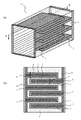
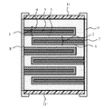
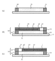
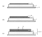
図1(a)に実施形態の電池を示す斜視図、図1(b)は電池を図1(a)のA−A´方向から下方向に切断した際の断面図である。また図2は電池の別の形態を示す断面図である。図1、図2において同じ符号は同一の部材を示す。
図1(a)、図2に示すように電池要素10は、正極1、負極2、無機固体電解質3を具備する。正極1と負極2とが無機固体電解質層3を介して対向するように互いに間隔を持ちつつかみ合っており、その間に無機固体電解質3が充填されている。
An embodiment is illustrated in FIGS. 1 and 2, and this embodiment will be described below with reference to the drawings.
FIG. 1A is a perspective view showing the battery of the embodiment, and FIG. 1B is a cross-sectional view when the battery is cut downward from the AA ′ direction in FIG. FIG. 2 is a cross-sectional view showing another embodiment of the battery. 1 and 2, the same reference numerals indicate the same members.
As shown in FIG. 1A and FIG. 2, the
図1(b)、図2に示すように正極1は、互いに間隔を持って並列した複数の正極集電体層5、各々の正極集電体層5の端面に接続して複数の正極集電体層5を互いに導通させ外部に電流を取り出す正極端子8、正極集電体層5の、正極端子8が接続した面以外の端面と両面を被覆する焼結式正極活物質層4(以下、正極活物質層4)を具備する。図1(b)のように正極集電体層5のみならず正極端子8表面も正極活物質層4で連続して被覆されていることが電極面積増加の点で望ましいが、図2に示すように、正極集電体層5の、正極端子8が接続した面以外の端面と両面のみが正極活物質層4で被覆されたものであっても良い。
As shown in FIG. 1B and FIG. 2, the
負極2は、互いに間隔を持って並列した複数の負極集電体層7、各々の負極集電体層7の端面に接続して複数の負極集電体層7を互いに導通させ外部に電流を取り出す負極端子9、負極集電体層7の、負極端子9が接続した面以外の端面と両面を被覆する焼結式負極活物質層6(以下、負極活物質層6)を具備する。図1(b)のように負極集電体層7のみならず負極端子9表面も負極活物質層6で連続して被覆されていることが電極面積増加の点で望ましいが、図2に示すように、負極集電体層7の、負極端子9が接続した面以外の端面と両面のみが負極活物質層6で被覆されたものであっても良い。
The
焼結式無機固体電解質3は、前記正極活物質層4及び前記負極活物質層6間に挟持されている。
The sintered inorganic
さらに図2に示すように電池要素10の上下に前記電池要素を挟む一対の絶縁板11、11´をさらに具備していることが望ましい。このような絶縁板で覆われていることが、電池要素保護のために望ましい。
Further, as shown in FIG. 2, it is desirable to further include a pair of insulating
本実施形態の電池構造は特に小型電池に適しており、例えば正極活物質層4の厚さは500〜0.1μm、より好ましくは50〜1μm、正極集電体層5の厚さは500〜0.1μm、より好ましくは50〜1μm、無機固体電解質層3の厚さは500〜0.1μm、より好ましくは50〜1μm、負極活物質層6の厚さは500〜0.1μm、より好ましくは50〜1μm、負極集電体層7の厚さは500〜0.1μm、より好ましくは50〜1μm、の範囲が例示される。
The battery structure of this embodiment is particularly suitable for small batteries. For example, the thickness of the positive electrode
正極1の正極活物質層4について説明する。
正極活物質層4に用いられる正極活物質としては、種々の金属酸化物、金属硫化物などを用いることができる。特に金属酸化物が用いられる場合には、電池要素焼結を酸素雰囲気下で行うことが可能となり、得られる電池は、酸素欠陥が少なく、結晶性が高い活物質を得ることが可能になるため、理論容量に近い高容量な電池を作製できるため望ましい。
The positive electrode
As the positive electrode active material used for the positive electrode
二次電池用の正極活物質の具体例としては、二酸化マンガン(MnO2)、酸化鉄、酸化銅、酸化ニッケル、リチウムマンガン複合酸化物(例えばLixMn2O4またはLixMnO2)、リチウムニッケル複合酸化物(例えばLixNiO2)、リチウムコバルト複合酸化物(LixCoO2)、リチウムニッケルコバルト複合酸化物(例えばLiNi1−yCoyO2)、リチウムマンガンコバルト複合酸化物(例えばLiMnyCo1−yO2)、スピネル型リチウムマンガンニッケル複合酸化物(LixMn2−yNiyO4)、オリビン構造を有するリチウムリン酸化物(LixFePO4、LixFe1−yMnyPO4、LixCoPO4など)、硫酸鉄(Fe2(SO4)3)、バナジウム酸化物(例えばV2O5)などから選択される少なくとも一種が挙げられる。なお、これらの化学式中、x,yは0〜1の範囲であることが好ましい。) Specific examples of the positive electrode active material for the secondary battery include manganese dioxide (MnO 2 ), iron oxide, copper oxide, nickel oxide, lithium manganese composite oxide (for example, Li x Mn 2 O 4 or Li x MnO 2 ), Lithium nickel composite oxide (eg Li x NiO 2 ), lithium cobalt composite oxide (Li x CoO 2 ), lithium nickel cobalt composite oxide (eg LiNi 1-y Co y O 2 ), lithium manganese cobalt composite oxide ( for example LiMn y Co 1-y O 2 ), spinel type lithium-manganese-nickel composite oxide (Li x Mn 2-y Ni y O 4), lithium phosphates having an olivine structure (Li x FePO 4, Li x Fe 1 -y Mn y PO 4, etc. Li x CoPO 4), iron sulfate (Fe 2 (SO 4) 3 ) At least one selected from vanadium oxides (e.g. V 2 O 5) can be mentioned. In these chemical formulas, x and y are preferably in the range of 0-1. )
より好ましい正極活物質は、電池電圧が高いリチウムマンガン複合酸化物(LixMn2O4)、リチウムニッケル複合酸化物(LixNiO2)、リチウムコバルト複合酸化物(LixCoO2)、リチウムニッケルコバルト複合酸化物(LixNi1−yCoyO2)、スピネル型リチウムマンガンニッケル複合酸化物(LixMn2−yNiyO4)、リチウムマンガンコバルト複合酸化物(LixMnyCo1−yO2)、リチウムリン酸鉄(LixFePO4)などが挙げられる。(なお、x,yは0〜1の範囲であることが好ましい。)これらの正極活物質は酸化性の雰囲気下での焼結により結晶性が向上し電池特性を向上させる。 More preferable positive electrode active materials include lithium manganese composite oxide (LixMn 2 O 4 ), lithium nickel composite oxide (Li x NiO 2 ), lithium cobalt composite oxide (Li x CoO 2 ), and lithium nickel cobalt having a high battery voltage. complex oxide (Li x Ni 1-y Co y O 2), spinel type lithium-manganese-nickel composite oxide (Li x Mn 2-y Ni y O 4), lithium manganese cobalt composite oxide (Li x Mn y Co 1 -y O 2), lithium iron phosphate (Li x FePO 4), and the like. (Note that x and y are preferably in the range of 0 to 1.) These positive electrode active materials have improved crystallinity and improved battery characteristics by sintering in an oxidizing atmosphere.
次に負極活物質層6に用いられる負極活物質について説明する。二次電池用の負極活物質層6に用いられる負極活物質は、金属リチウム、若しくはリチウム合金が挙げられる。前記リチウム合金としてはリチウム及びSn、In、Znから選択される少なくとも一種の合金が、容量が大きいため薄型化が可能となり、界面での応力を抑制できるために望ましい。具体的な合金組成としては、Li4.4Sn、LiIn、LiZnなどが挙げられ、特にLi4.4Snなどが高容量で薄膜化が可能であるため望ましい。
Next, the negative electrode active material used for the negative electrode
金属リチウム、若しくはリチウム合金の負極活物質層6は、電池組み立て後、初回充電時に析出形成することができる。負極集電体層7として導電性金属酸化物を用いた場合、正極活物質層4もしくは無機固体電解質層3から放出されるリチウムイオンと反応する材料(たとえば錫酸化物、インジウム酸化物、亜鉛酸化物)である場合には、無機固体電解質層3と負極集電体層7の間に負極活物質層6となるリチウム合金層が形成される。また、負極集電体層7として導電性金属酸化物を用いた場合、負極集電体層7である導電性金属酸化物が、正極から放出されるリチウムイオンと反応しない材料(例えばチタン酸化物)である場合には、無機固体電解質層3と負極集電体層7の間に負極活物質層6となる金属リチウム層が形成される。このような充電によって形成される負極活物質層6は、隣接する無機固体電解質3、あるいは負極集電体層7との接合性に富む良好な界面が形成される。この結果、界面抵抗が小さい優れた電池を作製できる。
The negative electrode
また、二次電池用の負極活物質層6に用いられる負極活物質は、負極2の作動電位が金属リチウムの電位に対して1.0Vよりも貴となる活物質を用いてもよい。負極集電体7に導電性金属酸化物を用いた場合、リチウムイオンを挿入・脱離する電位は1.0V以下である。したがって負極活物質層6でリチウムイオンの挿入・脱離反応が進行する電位で、負極集電体層7の導電性金属酸化物がリチウムイオンと反応することはない。したがって負極集電体層7の導電性金属酸化物の反応によって負極活物質自体の電極反応を阻害することがなく、電池の繰り返し寿命が向上する。
Moreover, the negative electrode active material used for the negative electrode
さらに、負極の作動電位が金属リチウムの電位に対して1.0Vよりも貴となる活物質であって、かつ導電性を有し、リチウムイオンの挿入・脱離反応の可逆性が高い物質であり、さらにリチウムイオンの吸蔵・放出の際に体積変化が小さく、さらに加熱によって大きく変質しない物質が用いられることが望ましく、具体的には、酸化タングステン(例えばWOa(1.8<a<2.2)、負極の作動電位1.0〜1.4V)、酸化モリブデン(例えばMoOb(1.8<b<2.2)、負極の作動電位1.0〜1.4V)、硫化鉄(例えばFecS(0.9<c<1.1)、負極の作動電位約1.8V)、硫化鉄リチウム(LixFeSy(0≦x≦4、0.9≦y≦2.1)、負極の作動電位約1.8V)、硫化チタン(例えばTiSd(1.8<d<2.2)、負極の作動電位1.5〜2.7V)、チタン酸リチウム(例えばLi4+zTi5O12(0≦z≦3)、負極の作動電位約1.55V)などの金属酸化物や金属硫化物を用いることができる。これらは単独で用いてもよく、または2種以上混合して用いても良い。特にリチウムと鉄を含む複合硫化物、あるいはリチウムとチタンを含む複合酸化物であることが望ましく、中でもLixFeSy(0≦x≦4、0.9≦y≦2.1)で表される硫化鉄(負極の作動電位約1.8V)はリチウムイオンの吸蔵量が多く電池容量をより高くするため望ましい。また、化学式Li4+xTi5O12(0≦x≦3)で表されスピネル型構造を有するチタン酸リチウム(負極の作動電位約1.55V)はリチウム吸脱反応時の結晶構造の変化が小さく、電池の充放電サイクル寿命をより伸ばすことができるため望ましい。 Furthermore, it is an active material in which the operating potential of the negative electrode is nobler than 1.0 V with respect to the potential of metallic lithium, has conductivity, and has high reversibility of lithium ion insertion / extraction reactions. In addition, it is desirable to use a material that has a small volume change upon occlusion / release of lithium ions and that does not change greatly upon heating. Specifically, tungsten oxide (for example, WO a (1.8 <a <2 .2), negative electrode operating potential 1.0 to 1.4 V), molybdenum oxide (eg MoO b (1.8 <b <2.2), negative electrode operating potential 1.0 to 1.4 V), iron sulfide (For example, Fe c S (0.9 <c <1.1), negative electrode operating potential of about 1.8 V), lithium iron sulfide (Li x FeS y (0 ≦ x ≦ 4, 0.9 ≦ y ≦ 2. 1), negative electrode operating potential of about 1.8 V), titanium sulfide (for example, T iS d (1.8 <d <2.2), negative electrode operating potential 1.5 to 2.7 V), lithium titanate (for example, Li 4 + z Ti 5 O 12 (0 ≦ z ≦ 3), negative electrode operating potential) A metal oxide or metal sulfide such as about 1.55 V) can be used. These may be used alone or in combination of two or more. In particular, it is preferably a composite sulfide containing lithium and iron, or a composite oxide containing lithium and titanium, and is represented by Li x FeS y (0 ≦ x ≦ 4, 0.9 ≦ y ≦ 2.1). Iron sulfide (operating potential of the negative electrode of about 1.8 V) is desirable because it has a large amount of lithium ion storage and increases battery capacity. Further, lithium titanate represented by the chemical formula Li 4 + x Ti 5 O 12 (0 ≦ x ≦ 3) and having a spinel structure (negative electrode operating potential of about 1.55 V) has a small change in crystal structure during lithium adsorption / desorption reaction. It is desirable because the charge / discharge cycle life of the battery can be further extended.
次に、正極集電体層5及び負極集電体層7について説明する。
正極集電体層5、負極集電体層7の少なくとも一方は、導電性金属酸化物層を用いることが望ましい。導電性金属酸化物層とは、導電性金属酸化物同士が一体化しており層状の形状を構成したものを指す。層内に微小な孔を有する多孔質体であっても良い。この材料の適用により、電極、電解質及び集電体を同時に焼結することが可能であり、それにより活物質の結晶性が高くなり導電性がさらに向上するため、優れた電池特性を得る上で非常に適している。
Next, the positive electrode
At least one of the positive electrode
正極集電体層5及び負極集電体層7のどちらか一方に、導電性金属酸化物を用いない場合は、負極の充放電電位でリチウムと反応しない銅やニッケルなどの金属、合金製集電体を用いることは可能であるが、正極集電体層5及び負極集電体層7共に導電性金属酸化物層を用いることが特に望ましい。
When a conductive metal oxide is not used for either the positive electrode
前記導電性金属酸化物としては、Sn、In、Zn、Tiから選ばれる少なくとも1種の元素の酸化物が挙げられる。さらに具体的には、SnO2、In2O3、ZnO、TiOx(0.5≦x≦2)が挙げられる。これら導電性金属酸化物には、構造中にSb、Nb、Taなど導電性を高めるための微量元素を(例えば10at%以下)含んでも良い。 Examples of the conductive metal oxide include oxides of at least one element selected from Sn, In, Zn, and Ti. More specifically, SnO 2, In 2 O 3 , ZnO, TiO x (0.5 ≦ x ≦ 2) and the like. These conductive metal oxides may contain a trace element (for example, 10 at% or less) for enhancing conductivity such as Sb, Nb, Ta in the structure.
無機固体電解質3について説明する。
無機固体電解質3にはイオン導電性があり、電子伝導性が無視できるほど小さい材料を用いる。無機固体電解質3はリチウムを含むものを用い、この二次電池はリチウムイオンが可動イオンとする。例えば、Li3PO4をはじめ、Li3PO4に窒素を混ぜたLiPO4−xNx(xは0<x≦1)、Li2S−SiS2、Li2S−P2S5、Li2S−B2S3等のリチウムイオン伝導性ガラス状固体電解質や、これらのガラスにLiIなどのハロゲン化リチウム、Li3PO4などのリチウム酸素酸塩をドープしたリチウムイオン伝導性固体電解質などは、リチウムイオン伝導性が高く、有効である。中でも、リチウムとチタンと酸素を含むチタン酸化物型の固体電解質、例えば、LixLayTiO3(xは0<x<1、yは0<y<1)などは酸素雰囲気下での焼成においても安定な性能を示すため好ましい。
The inorganic
The inorganic
正極端子8、負極端子9について説明する。
正極端子8、負極端子9を構成する材料は特に限定されない。例えば、Ag、Ag/Pd合金、Niメッキ、蒸着によるCuなどが挙げられる。また、外部電極表面には実装のための半田メッキなどをおこなっても良い。正極端子8、負極端子9は同じである必要は無く、必要に応じて異なるものを用いても良い。また、表面状態や形状にバリエーションを持たり、色付けしたり、あるいは刻印を打ったりすることで正負を明確に示すための実用的な仕様としてもよい。
The
The material which comprises the
無機固体電解質電池を構成する正極1、後述する負極2、無機固体電解質3、正極端子8、負極端子9などに対して、例えばSiO2、Al2O3、PbO、MgOなどの無機物が混合されていてもよいし、PVBやMEKなどの有機物を含んでいても良い。
For example, inorganic materials such as SiO 2 , Al 2 O 3 , PbO, and MgO are mixed with the
電池の形状について、図1には、四角柱形状の電池の例を示したが電池形状はこれに限定されない。例えばボタン型、円筒型などであってもよい。 Regarding the shape of the battery, FIG. 1 shows an example of a quadrangular prism-shaped battery, but the battery shape is not limited to this. For example, a button type or a cylindrical type may be used.
以上の如くの電池の構成を採用することにより、正極、負極、無機固体電解質を一括して焼結する製造プロセスを採用でき、例えば、以下のような簡便なプロセスで無機固体電解質二次電池を完成させることができる。 By adopting the battery configuration as described above, it is possible to adopt a manufacturing process in which the positive electrode, the negative electrode, and the inorganic solid electrolyte are sintered together. For example, the inorganic solid electrolyte secondary battery can be manufactured by the following simple process. Can be completed.
次に二次電池の製造方法について説明する。
図3〜図5は二次電池製造プロセスの一実施形態を示す概略断面図である。
Next, a method for manufacturing a secondary battery will be described.
3 to 5 are schematic cross-sectional views showing an embodiment of a secondary battery manufacturing process.
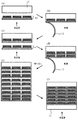
(無機固体電解質シート形成工程)
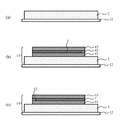
図3(a)に示すようにポリエチレンテレフタレート(PET)製などのシート状支持体12の一方の面上に部分的に無機固体電解質層3を形成した無機固体電解質シートを用意する。
(Inorganic solid electrolyte sheet forming process)
As shown in FIG. 3A, an inorganic solid electrolyte sheet in which an inorganic
(正極シート形成工程(1))
次に図3(b)に示すように、無機固体電解質シートの前記無機固体電解質層3上に、第1正極活物質領域41を具備する第1正極層、前記第1正極層上に、正極集電体領域5と前記正極集電体領域5を平面方向に囲む第2正極活物質領域42とを備える第2正極層、前記第2正極層上に、第3正極活物質領域43を具備する第3正極層を順次積層した正極シート13を形成する。この正極シート13は複数形成する。なお、前記第2正極層においては、図3(b)に示すように、前記正極集電体領域5全てを第2正極活物質領域42で囲まず、正極端子8に接続される面で端部が露出するように構成するか、また、前記正極集電体領域5全てを第2正極活物質領域42で囲んで後工程で切断し正極端子8に接続される面で端部が露出するようにすれば良い。
(Positive electrode sheet forming step (1))
Next, as shown in FIG. 3B, a first positive electrode layer having a first positive electrode
(負極シート形成工程(1))
また図3(c)に示すように、別の前記無機固体電解質シートの前記無機固体電解質層3上に、第1負極活物質領域61を具備する第1負極層、前記第1負極層上に、負極集電体領域7と前記負極集電体領域7を平面方向に囲む第2負極活物質領域62とを備える第2負極層、前記第2負極層上に、第3負極活物質領域63を具備する第3負極層を順次積層した負極シート14を形成する。ただし負極活物質層を後工程の初充電により析出させて形成する電池の場合には負極活物質領域をあらかじめ準備しておくことは不要である。この負極シート14は複数形成する。なお、前記第2負極層においては、図3(b)に示すように、前記負極集電体領域7全てを第2負極活物質領域62で囲まず、後に負極端子9に接続される面で端部が露出するように構成するか、また、前記負極集電体領域6全てを第2負極活物質領域62で囲んで後工程で切断し負極端子9に接続される面で端部が露出するようにしても良い。
(Negative electrode sheet forming step (1))
Further, as shown in FIG. 3C, on the inorganic
(正極シート・負極シート形成工程(2))
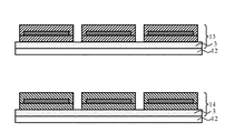
上記した、正極シート形成工程(1)、負極シート形成工程(1)に記載した方法の他にも以下のようにして、正極シート13、負極シート14を形成しても良い。すなわち、図9(a)に示すように、まず、無機固体電解質シートの無機固体電解質層3上に、正極又は負極の第1番目の活物質領域71を具備する第1番目の活物質層を積層し、次に図9(b)に示すように前記第1番目の活物質層上に、正極又は負極集電体領域80を備える集電体層を積層し、次に図9(c)に示すように前記集電体層上に、第2番目の活物質領域72を具備する第2番目の活物質層を順次積層した正極又は負極シートを形成する。ただし負極活物質層を後工程の初充電により析出させて形成する電池の場合には負極活物質領域をあらかじめ準備しておくことは不要である。この活物質シートは複数形成する。なお、前記第2番目の活物質領域72は、集電体領域80よりも面積を大きくして、集電体領域80の端部を覆い、第1番目の活物質領域と接するように形成する。ただし前記第2番目の活物質層においては、図9(c)に示すように、前記集電体領域80全てを第5活物質領域72で囲まなくとも、負極端子9に接続される面で端部が露出するように構成しても良い。また、前記集電体領域80全てを第2番目の活物質領域72で囲んで後工程で切断し負極端子9に接続される面で端部が露出するようにしても良い。
(Positive electrode sheet / negative electrode sheet forming step (2))
In addition to the methods described in the positive electrode sheet forming step (1) and the negative electrode sheet forming step (1), the
上記(1)、(2)の方法における正極シート13若しくは負極シート14の各層の形成は、例えば各部材の構成材料をバインダー(例えば、ポリフッ化ビニリデン、ポリビニルブチラール、スチレンブタジエンゴムなど)及び溶媒(N−メチルピロリドン、MEK、水など)で混練したスラリーをスクリーン印刷やドクターブレード法、グラビア印刷法で、必要とする厚みに塗布形成することで形成することができる。各層を構成する材料が互いに相溶する場合でも各層を形成した後、溶媒を乾燥させ次の層を形成することを繰り返せばよい。
The formation of each layer of the
また、上記(1)、(2)で形成される正極シート及び負極シート、及び電解質シートにおいて、電極活物質領域を部分的にパターン形成した領域を加え、電池が形成された際に電極端子と無機固体電解質層との間に電極活物質領域が存在し、集電体のみならず電極端子表面も活物質層で連続して被覆されているよう構成することもできる。 Further, in the positive electrode sheet, the negative electrode sheet, and the electrolyte sheet formed in the above (1) and (2), a region in which the electrode active material region is partially patterned is added, and when the battery is formed, An electrode active material region may exist between the inorganic solid electrolyte layer and the electrode terminal surface as well as the current collector may be continuously covered with the active material layer.
なお、上記正極シート形成工程及び負極シート形成工程(1)、(2)で形成される正極シート、負極シートは、図4に示すように一枚のシート状支持体12の一方の面上に無機固体電解質層3を形成した無機固体電解質シートに対して、第1〜第3正極層の積層したもの若しくは第1〜第3負極層の積層したものを複数組形成した正極シート13若しくは負極シート14であっても良く、それは大量生産に適している。
The positive electrode sheet and the negative electrode sheet formed in the positive electrode sheet forming step and the negative electrode sheet forming step (1) and (2) are on one surface of a sheet-
(積層工程)
次に前記第1負極活物質領域63と前記第3正極活物質領域41、もしくは第3負極活物質領域63と第1正極活物質領域41、が前記無機固体電解質層3を介して向き合うよう、前記シート状支持体12が除去された複数の正極シート13と前記複数の負極シート14とを交互に積層して積層体を形成する。
(Lamination process)
Next, the first negative electrode
例えば、図5(a)に示すように、あらかじめ準備しておいた、積層最外層となる絶縁層15(例えば生セラミックグリーンシート層)に正極シート13を、熱圧着し、次に図5(b)に示すように、シート状支持体12を剥離する。次に図5(c)に示すように、先に圧着した正極シート13に負極シート14を熱圧着し、図5(d)に示すようにシート状支持体12を剥離する。この操作を図5(e)に示すように必要な回数繰り返し、最後に図5(f)に示すように積層最外層となる絶縁層16を熱圧着し、電池要素前駆体となる積層体を得ることができる。この電池要素前駆体の各層を一体化させる所定の治具に入れ、静水圧処理を行う。
For example, as shown in FIG. 5A, the
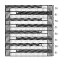
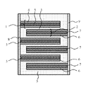
なお、絶縁層15、16としては生セラミックグリーンシート層に対し例えばSiO2、Al2O3、PbO、MgOなどの無機物が混合されていてもよいし、PVBやMEKなどの有機物を含んでいても良い。また正極層、負極層、無機固体電解質の積層体との焼結時の密着性を上げるためにこれと接触する無機固体電解質または正極あるいは負極層の成分を含んでいることが望ましい。最外層絶縁体の積層状態はこの例に限定されるものでは無い。最外層に絶縁層が配置されている他の例を図10、図11に示した。図10、図11においてはいずれも正極シート50、負極シート51が交互に積層されているが、図10においては電極活物質層に絶縁層が接している。図11においては電解質層に絶縁層が接している。
The insulating layers 15 and 16 may be mixed with inorganic materials such as SiO 2 , Al 2 O 3 , PbO, and MgO with respect to the raw ceramic green sheet layer, and may contain organic materials such as PVB and MEK. Also good. In addition, in order to increase the adhesion during sintering with the positive electrode layer, the negative electrode layer, and the laminate of the inorganic solid electrolyte, it is desirable to include an inorganic solid electrolyte or a component of the positive electrode or the negative electrode layer in contact therewith. The laminated state of the outermost layer insulator is not limited to this example. Other examples in which an insulating layer is disposed as the outermost layer are shown in FIGS. 10 and 11,
(切断工程)
次に必要に応じて端面に正極集電体5および、負極集電体7の端面が、積層体の、それぞれ別の面で露出するよう前記積層体を切断する。
(Cutting process)
Next, the laminated body is cut as necessary so that the end faces of the positive electrode
(焼結工程)
次に前記積層体を加熱し焼結する。さらに、この電池要素前駆体を500℃以上1500℃以下、望ましくは700℃以上900℃以下の温度条件にて高温焼結する。焼結時の雰囲気は材料に酸化物を用いている場合、酸化雰囲気で行われることが望ましい。例えば酸素含有雰囲気が良く、特に大気雰囲気中で行われることが最も簡便であるが、集電体金属を保護するためなど原料によっては酸化還元反応を調整する目的で各種雰囲気を調整して行われても全く支障はない。焼成時間は0.1〜10時間の範囲であることが望ましい。
(Sintering process)
Next, the laminate is heated and sintered. Further, the battery element precursor is sintered at a high temperature under a temperature condition of 500 ° C. or higher and 1500 ° C. or lower, desirably 700 ° C. or higher and 900 ° C. or lower. When an oxide is used as the material, the sintering atmosphere is preferably performed in an oxidizing atmosphere. For example, an oxygen-containing atmosphere is good, and it is most convenient to perform in an air atmosphere in particular, but depending on the raw materials, such as to protect the current collector metal, various atmospheres are adjusted for the purpose of adjusting the redox reaction. But there is no problem at all. The firing time is desirably in the range of 0.1 to 10 hours.
(正極・負極端子接続工程)
次に研磨などの表面処理を施し、前記露出した複数の正極集電体5を電気的に接続する正極端子8を接続し、前記露出した複数の負極集電体7を電気的に接続する負極端子9を接続する。研磨などの表面処理は加工時のバリを取るだけでなく、表面を滑らかにすることで欠けなどを防ぐ効果があり、アルミナなどの研磨粉で行う。正極、負極端子8,9は導電性ペーストなどでそれぞれ接合する。正極・負極端子は材料をバインダーと共にペースト状とし、焼結工程前に、前記ペーストを端子取り付け位置に塗布し、電池要素と共に焼結することにより取り付けても良い。
(Positive / negative terminal connection process)
Next, surface treatment such as polishing is performed, the
その後、乾燥した後、樹脂コーティングによる外装をディッピングなどでコーティングして硬化させても電池を完成させることができる。初充電することによって、負極活物質層を形成させる場合は、この後、充電工程を行うことによって、固体電解質層3と負極集電体層7間に負極活物質層6が析出する。
Then, after drying, the battery can be completed by coating and curing the exterior by resin coating by dipping or the like. When the negative electrode active material layer is formed by initial charging, the negative electrode
以下に例を挙げ、本発明をさらに詳しく説明するが、発明の主旨を超えない限り本発明は以下に掲載される実施例に限定されるものでない。 Hereinafter, the present invention will be described in more detail with reference to examples. However, the present invention is not limited to the following examples as long as the gist of the invention is not exceeded.
(実施例1)
以下の手順にて方法にて二次電池を作製した。二次電池の構造を示す概略断面図を図2に、二次電池の製造過程の一部を示す概略断面図を図3に示す。
(Example 1)
A secondary battery was produced by the following procedure. FIG. 2 is a schematic sectional view showing the structure of the secondary battery, and FIG. 3 is a schematic sectional view showing a part of the manufacturing process of the secondary battery.
<無機固体電解質シートの作製>
無機固体電解質としてチタン酸ランタンリチウム(LixLayTiO3)粉末100重量部、重合度200〜300のポリビニルブチラール(PVB)をバインダーとして5重量部、可塑剤としてフタル酸ジブチル(DBP)2重量部と溶剤(MEKとアセトンを1:1に混合)20重量部を混合してスラリーとし、このスラリーを脱泡して無機固体電解質セラミック用スラリーを作製した。
<Preparation of inorganic solid electrolyte sheet>
Lanthanum titanate lithium (Li x La y TiO 3) powder 100 parts by weight of the inorganic solid electrolyte, 5 parts by weight polyvinyl butyral (PVB) as a binder having a degree of polymerization of 200 to 300, dibutyl phthalate (DBP) 2 weight as a plasticizer Part and 20 parts by weight of solvent (mixed MEK and acetone 1: 1) were mixed to form a slurry, and this slurry was defoamed to prepare an inorganic solid electrolyte ceramic slurry.
このスラリーをポリエチレンテレフタレート(PET)製シート状支持体キャリアシート12上に塗布、乾燥させ、キャリアシート12に無機固体電解質層3を形成した図3(a)に示す無機固体電解質シートを作製した。
This slurry was applied on a polyethylene terephthalate (PET) sheet-like
<正極シートの作製>
上記正極シート形成工程(1)に記載した方法にて正極シートを作製した。
次に正極活物質としてコバルト酸リチウム(LiCoO2)粉末100重量部、PVBを5重量部、DBPを2重量部、上記組成の溶剤22重量部を混合してスラリーとし、このスラリーを脱泡して、正極活物質用スラリーを作製した。
<Preparation of positive electrode sheet>
A positive electrode sheet was produced by the method described in the positive electrode sheet forming step (1).
Next, 100 parts by weight of lithium cobalt oxide (LiCoO 2 ) powder as a positive electrode active material, 5 parts by weight of PVB, 2 parts by weight of DBP, and 22 parts by weight of the solvent having the above composition are mixed to form a slurry, and this slurry is defoamed. Thus, a positive electrode active material slurry was prepared.
このスラリーを無機固体電解質シートの無機固体電解質層3上に塗布、乾燥させ、複数の第1の正極活物質領域41を具備する第1正極層を形成した。
This slurry was applied onto the inorganic
次にアンチモンをドープしたスズ酸化物(SnO2)粉末100重量部、PVB5重量部DBP2重量部を上記組成の溶剤18重量部にて混合してスラリーとし、このスラリーを脱泡して正極集電体用スラリーを作製した。 Next, 100 parts by weight of antimony-doped tin oxide (SnO 2 ) powder and 5 parts by weight of PVB and 2 parts by weight of DBP were mixed with 18 parts by weight of the solvent of the above composition to form a slurry. A body slurry was prepared.
このスラリーを上記第1正極活物質領域41上に塗布、乾燥させ、前記無機固体電解質層3の上に正極集電体領域5を形成した。さらに前記正極活物質スラリーを用い、前記正極集電体領域5を平面方向に囲む第2正極活物質領域42を形成し、正極集電体領域5と正極活物質領域42とを備える第2正極層を形成した。つぎに前記正極活物質スラリーを用い、前記第2正極層上に、第3正極活物質領域43を具備する第3正極層を順次積層した。このようにして図3(b)に示す正極シート13を形成した。
This slurry was applied on the first positive electrode
<負極シートの作製>
上記負極シート形成工程(1)に記載した方法にて正極シートを作製した。
負極活物質としてチタン酸リチウム(Li4Ti5O12)粉末100重量部、PVBを5重量部、DBPを2重量部、上記溶剤22重量部を混合しスラリーとし、このスラリーを脱泡して負極活物質用スラリーを作製した。
<Preparation of negative electrode sheet>
A positive electrode sheet was produced by the method described in the negative electrode sheet forming step (1).
As a negative electrode active material, 100 parts by weight of lithium titanate (Li 4 Ti 5 O 12 ) powder, 5 parts by weight of PVB, 2 parts by weight of DBP, and 22 parts by weight of the solvent were mixed to form a slurry. A slurry for negative electrode active material was prepared.
このスラリーを無機固体電解質シートの無機固体電解質層3上に塗布、乾燥させ、複数の第1の負極活物質領域61を具備する第1負極層を形成した。
This slurry was applied onto the inorganic
次にアンチモンをドープしたスズ酸化物(SnO2)粉末100重量部、PVB5重量部DBP2重量部を上記組成の溶剤18重量部にて混合してスラリーとし、このスラリーを脱泡して負極集電体用スラリーを作製した。 Next, 100 parts by weight of antimony-doped tin oxide (SnO 2 ) powder and 5 parts by weight of PVB and 2 parts by weight of DBP were mixed with 18 parts by weight of the solvent having the above composition to form a slurry. A body slurry was prepared.
このスラリーを上記第1負極層上に塗布、乾燥させ、前記無機固体電解質層3の上に負極集電体層領域7を形成した。さらに前記負極活物質スラリーを用い、前記負極集電大量域7を平面方向に囲む第2負極活物質領域62を形成し、負極集電体領域7と負極活物質領域62とを具備する第2負極層を形成した。次に前記負極活物質スラリーを用い、前記第2負極層上に、第3負極活物質領域63を具備する第3負極層を順次積層した。このようにして図3(c)に示す負極シート14を形成した。
This slurry was applied on the first negative electrode layer and dried to form a negative electrode current
<積層・切断・焼結工程>
得られた正極シートおよび負極シートからキャリアシート12を剥離しつつ両者を交互に順次積層させ有効積層数10層の積層帯(電池要素前駆体)を形成し、これをアルミナを主成分とするセラミックスのカバーシート11、11´で挟み込み静水圧プレスによりラミネートし、正極・負極集電体が積層体のそれぞれ異なる面で露出するように個々の電池要素に切断した後に、これを脱脂して酸素気流中900℃で1時間焼成した。
<Lamination, cutting and sintering process>
While peeling the
<正極・負極端子接続工程>
得られた電池要素の正極集電体5、負極集電体7にそれぞれ接続する正極端子8、負極端子9を取り付けた後、2.8Vまで充電し、図2に断面を示す無機固体電解質二次電池を完成させた。
<Positive electrode / negative electrode terminal connection process>
After attaching the
<電池の評価>
完成した電池の容量は200μAh、500サイクル後の容量維持率は98%であった。
サイクル寿命後の電池を分解、SEMにて観察調査した結果、集電体端面が活物質で覆われており、無機固体電解質層に亀裂などの欠陥は観察されなかった。なお、サイクル寿命試験は20℃で行い、充電電流1C、放電電流1Cとし、充電及び放電終止電圧は2.8V、1.5Vとして充放電サイクルを繰り返して容量維持率を測定した。
<Battery evaluation>
The capacity of the completed battery was 200 μAh, and the capacity retention rate after 500 cycles was 98%.
As a result of disassembling the battery after the cycle life and observing it with an SEM, the end face of the current collector was covered with the active material, and no defects such as cracks were observed in the inorganic solid electrolyte layer. The cycle life test was performed at 20 ° C., charging current 1C and discharging current 1C, charging and discharging end voltages were 2.8 V and 1.5 V, and the capacity maintenance rate was measured by repeating the charging and discharging cycle.
なお、本実施例においては、正極シート形成工程(1)・負極シート形成工程(1)に記載した方法にて正極シート及び負極シートを作製したが、正極シート・負極シート形成工程(2)に記載された方法にても本実施例とほぼ同様な特性を有する電池が得られることを確認した。 In this example, the positive electrode sheet and the negative electrode sheet were prepared by the method described in the positive electrode sheet forming step (1) and the negative electrode sheet forming step (1). It was confirmed that a battery having substantially the same characteristics as in this example can be obtained even by the described method.
なお正極シート形成工程(1)、負極シート形成工程(1)を採用して積層電池を作製した場合、正極・負極それぞれの端子と接続されない端部において段差が生じないため多く積層する場合はデラミネーションなどの不良が発生しにくいという利点がある。また、正極シート形成工程(2)・負極シート形成工程(2)は製造工程が簡略化出来る点で有利である。具体的には30層程度までは正極シート形成工程(2)・負極シート形成工程(2)が採用され、30層を超える場合は正極シート形成工程(1)・負極シート形成工程(1)が採用されることが望ましい。 In addition, when a laminated battery is manufactured by adopting the positive electrode sheet forming step (1) and the negative electrode sheet forming step (1), there is no step at the end portion that is not connected to the terminals of the positive electrode and the negative electrode. There is an advantage that defects such as lamination hardly occur. The positive electrode sheet forming step (2) and the negative electrode sheet forming step (2) are advantageous in that the manufacturing process can be simplified. Specifically, the positive electrode sheet forming step (2) and the negative electrode sheet forming step (2) are employed up to about 30 layers, and when the layer exceeds 30 layers, the positive electrode sheet forming step (1) and the negative electrode sheet forming step (1) are performed. It is desirable to be adopted.
(実施例2)
この実施例2は、正極シート及び負極シート、及び電解質シートにおいて、さらに電極活物質領域を部分的にパターン形成した領域を増やし、電池が形成された際に正極若しくは負極端子と電解質との間に電極活物質領域が存在し、集電体のみならず電極端子表面も活物質層で連続して被覆されているようにした電池を形成した例である。
(Example 2)
In Example 2, in the positive electrode sheet, the negative electrode sheet, and the electrolyte sheet, a region in which the electrode active material region is partially patterned is further increased, and when the battery is formed, the positive electrode or negative electrode terminal and the electrolyte are interposed. This is an example in which a battery in which an electrode active material region exists and not only a current collector but also an electrode terminal surface is continuously covered with an active material layer is formed.
実施例1と同様に無機固体電解質用スラリー、正極・負極活物質用スラリー、正極・負極集電体スラリーを作製した。また実施例1と同様に無機固体電解質シートを作製した。次に正極シート及び負極シートを以下に示すように作製した。二次電池の製造過程の一部を示す概略断面図を図6に示す。 In the same manner as in Example 1, an inorganic solid electrolyte slurry, a positive electrode / negative electrode active material slurry, and a positive electrode / negative electrode current collector slurry were prepared. Moreover, the inorganic solid electrolyte sheet was produced similarly to Example 1. FIG. Next, a positive electrode sheet and a negative electrode sheet were produced as shown below. FIG. 6 is a schematic sectional view showing a part of the manufacturing process of the secondary battery.
<無機固体電解質シートの作製>
まず、図6(a)に示すようにシート状支持体12上に無機固体電解質用スラリー、正極・負極活物質用スラリーを用い、無機固体電解質領域31とその両端に正極活物質領域44及び負極活物質領域64を具備する複合電極活物質シートを作製した。
<Preparation of inorganic solid electrolyte sheet>
First, as shown in FIG. 6A, an inorganic solid electrolyte slurry and a positive electrode / negative electrode active material slurry are used on a sheet-
<正極シートの作製>
次に前記複合電極活物質シートの正極活物質領域44および無機固体電解質領域31上にまたがるように第1正極活物質領域41を部分的に形成した。また、無機固体電解質領域31上に隙間埋め用無機固体電解質領域32を、負極活物質領域64上に同じく負極活物質領域65を形成した。次に前記第1正極活物質領域41上に正極集電体領域5及び前記正極集電体領域5を平面方向に囲む第2正極活物質領域42を形成した後、前記正極集電体層5および前記第2正極活物質領域42上に第3正極活物質領域43を形成して正極シート50を得た(図6(b)。)
<Preparation of positive electrode sheet>
Next, a first positive electrode
<負極シートの作製>
前記複合電極活物質シートの負極活物質領域64及び無機固体電解質領域31上にまたがるように第1負極活物質領域61を部分的に形成した。また無機固体電解質領域31上に隙間埋め用無機固体電解質領域33を、正極活物質領域44上に同じく正極活物質領域45を形成した。次に前記第1負極活物質領域61に負極集電体領域7及び前記負極集電体領域7を平面方向に囲む第2負極活物質領域62を形成した後、前記負極集電体層7および前記第2負極活物質領域62に第3負極活物質領域63を形成して負極シート51を得た(図6(c))。
<Preparation of negative electrode sheet>
A first negative electrode
<積層・切断・焼結工程>
次に図7に示すように実施例1と同様にこれらの正極・負極シート50、51を交互に積層して、実施例1と同様のカバーシートで挟みラミネートした後、この後正極端面に正極集電体用スラリーを、負極端面に負極集電体用スラリーを塗布し乾燥させた。これを実施例1同様に脱脂、焼成の後、正極端子、負極端子を形成して無機固体電解質二次電池を完成させた。
<Lamination, cutting and sintering process>
Next, as shown in FIG. 7, these positive electrode /
<電池の評価>
完成した電池を実施例1と同様に評価したところ、容量は220μAh、500サイクル後の容量維持率は97%であった。サイクル寿命後の電池を分解、SEMにて観察調査した結果、電極端面が活物質で覆われており、無機固体電解質層に亀裂などの欠陥は観察されなかった。また、断面観察において電池端面において外部電極と無機固体電解質界面には活物質層が形成されており、外部電極と無機固体電解質が直接接触していなかった。
<Battery evaluation>
When the completed battery was evaluated in the same manner as in Example 1, the capacity was 220 μAh, and the capacity retention rate after 500 cycles was 97%. As a result of disassembling the battery after the cycle life and observing and investigating with SEM, the electrode end face was covered with the active material, and no defects such as cracks were observed in the inorganic solid electrolyte layer. In cross-sectional observation, an active material layer was formed at the interface between the external electrode and the inorganic solid electrolyte at the battery end face, and the external electrode and the inorganic solid electrolyte were not in direct contact.
また、強度試験として1.5mの高さから100回、厚さ10mmの鉄板上に落下させたところ破損したものは無く故障率は3%であった。故障評価は2.8Vまで充電した電池を使用し、落下試験後に容量が90%以下になったものを故障品として評価した。また、完全に破損したものは特に容量は測定せずに故障とした。 Further, as a strength test, when dropped on a steel plate having a thickness of 10 mm 100 times from a height of 1.5 m, there was no damage and the failure rate was 3%. For the failure evaluation, a battery charged to 2.8 V was used, and a battery whose capacity became 90% or less after the drop test was evaluated as a failure product. In addition, completely damaged ones were regarded as failures without measuring their capacity.
(比較例1)
以下の手順にて二次電池を作製した。二次電池の構造を示す概略断面図を図8に示す。
(Comparative Example 1)
A secondary battery was produced according to the following procedure. A schematic cross-sectional view showing the structure of the secondary battery is shown in FIG.
<無機固体電解質シートの作製>
無機固体電解質としてチタン酸ランタンリチウム(LixLayTiO3)粉末100重量部、重合度200〜300のポリビニルブチラール(PVB)をバインダーとして5重量部、可塑剤としてフタル酸ジブチル(DBP)2重量部と溶剤(MEKとアセトンを1:1に混合)20重量部を混合してスラリーとし、このスラリーを脱泡して無機固体電解質セラミック用スラリーを作製した。このスラリーをポリエチレンテレフタレート(PET)製キャリアシート上に塗布、乾燥させ、キャリアシートに無機固体電解質層3を形成した。
<Preparation of inorganic solid electrolyte sheet>
Lanthanum titanate lithium (Li x La y TiO 3) powder 100 parts by weight of the inorganic solid electrolyte, 5 parts by weight polyvinyl butyral (PVB) as a binder having a degree of polymerization of 200 to 300, dibutyl phthalate (DBP) 2 weight as a plasticizer Part and 20 parts by weight of solvent (mixed MEK and acetone 1: 1) were mixed to form a slurry, and this slurry was defoamed to prepare an inorganic solid electrolyte ceramic slurry. This slurry was applied on a polyethylene terephthalate (PET) carrier sheet and dried to form the inorganic
<正極シートの作製>
正極活物質としてコバルト酸リチウム(LiCoO2)粉末100重量部、PVBを5重量部、DBPを2重量部、上記組成の溶剤22重量部を混合してスラリーとし、このスラリーを脱泡して、正極活物質用スラリーを作製した。このスラリーを前記無機固体電解質シートの無機固体電解質層3上に塗布、乾燥させ、複数の正極活物質層4を形成した。
<Preparation of positive electrode sheet>
As a positive electrode active material, 100 parts by weight of lithium cobaltate (LiCoO 2 ) powder, 5 parts by weight of PVB, 2 parts by weight of DBP, and 22 parts by weight of the solvent having the above composition were mixed to form a slurry. A slurry for positive electrode active material was prepared. This slurry was applied onto the inorganic
次にアンチモンをドープしたスズ酸化物(SnO2)粉末100重量部、PVB5重量部DBP2重量部を上記組成の溶剤18重量部にて混合してスラリーとし、このスラリーを脱泡して正極集電体用スラリーを作製した。このスラリーを上記正極活物質層4上に塗布、乾燥させ、前記無機固体電解質層3の上に複数の正極集電体層5を形成した。
Next, 100 parts by weight of antimony-doped tin oxide (SnO 2 ) powder and 5 parts by weight of PVB and 2 parts by weight of DBP were mixed with 18 parts by weight of the solvent of the above composition to form a slurry. A body slurry was prepared. This slurry was applied on the positive electrode
次に上記正極活物質層と同様の方法で再び正極活物質層を上記複数の正極集電体層5上に塗布し乾燥させ、キャリアシート上に正極シートを作製した。この方法であると前記正極集電体領域5の端面を囲む正極活物質は形成されていない。
Next, the positive electrode active material layer was again applied on the plurality of positive electrode current collector layers 5 by the same method as that for the positive electrode active material layer and dried to prepare a positive electrode sheet on the carrier sheet. With this method, the positive electrode active material surrounding the end face of the positive electrode
<負極シートの作製>
負極活物質としてチタン酸リチウム(Li4Ti5O12)粉末100重量部、PVBを5重量部、DBPを2重量部、上記溶剤22重量部を混合しスラリーとし、このスラリーを脱泡して負極活物質用スラリーを作製した。このスラリーを上記無機固体電解質シートの無機固体電解質層3上に塗布、乾燥させ、複数の負極活物質層6を形成した。
<Preparation of negative electrode sheet>
As a negative electrode active material, 100 parts by weight of lithium titanate (Li 4 Ti 5 O 12 ) powder, 5 parts by weight of PVB, 2 parts by weight of DBP, and 22 parts by weight of the solvent were mixed to form a slurry. A slurry for negative electrode active material was prepared. This slurry was applied onto the inorganic
次にアンチモンをドープしたスズ酸化物(SnO2)粉末100重量部、PVB5重量部DBP2重量部を上記組成の溶剤18重量部にて混合してスラリーとし、このスラリーを脱泡して負極集電体用スラリーを作製した。このスラリーを上記負極活物質層6上に塗布、乾燥させ、前記無機固体電解質層3の上に複数の負極集電体層7を形成した。
Next, 100 parts by weight of antimony-doped tin oxide (SnO 2 ) powder and 5 parts by weight of PVB and 2 parts by weight of DBP were mixed with 18 parts by weight of the solvent having the above composition to form a slurry. A body slurry was prepared. This slurry was applied on the negative electrode
次に上記負極活物質層と同様の方法で再び負極活物質層6を上記複数の負極集電体層7の上に塗布、乾燥させ、キャリアシート上に負極シートを作製した。この方法であると前記負極集電体層7の端面を囲む負極活物質は形成されていない。
Next, the negative electrode
<積層・切断・焼結工程>
得られた正極複合シートおよび負極複合シートを交互に順次積層させ有効積層数10層の電池要素前駆体を形成し、これを実施例1と同様のカバーシートで挟み込み静水圧プレスによりラミネートし個々の電池要素に切断した後に、これを脱脂して酸素気流中900℃で1時間焼成した。
<Lamination, cutting and sintering process>
The obtained positive electrode composite sheet and negative electrode composite sheet were alternately laminated in order to form a battery element precursor having an effective lamination number of 10 layers. The battery element precursor was sandwiched between the same cover sheets as in Example 1 and laminated by an isostatic press. After cutting into battery elements, this was degreased and fired at 900 ° C. for 1 hour in an oxygen stream.
<正極・負極端子接続工程>
得られた電池要素の正極集電体5、負極集電体7にそれぞれ接続する外部電極8、9を取り付けた後、2.8Vまで充電し、無機固体電解質二次電池を完成させた。
<Positive electrode / negative electrode terminal connection process>
After attaching the
<電池の評価>
完成した電池の容量は200μAh、500サイクル後の容量維持率は73%であった。サイクル寿命後の電池を分解、SEMにて観察調査した結果、電極端面は活物質で覆われておらず、集電体と無機固体電解質が直接接しており界面付近に亀裂が生じていることが確認された。
<Battery evaluation>
The capacity of the completed battery was 200 μAh, and the capacity retention rate after 500 cycles was 73%. As a result of disassembling the battery after the cycle life and observing with SEM, the electrode end face is not covered with the active material, and the current collector and the inorganic solid electrolyte are in direct contact with each other, and there is a crack near the interface. confirmed.
また、実施例2と同様に落下試験を行ったところ外部電極が剥離するなどの破損が発生し、不良率は54%であった。
以上のように本発明は信頼性に優れた固体電解質二次電池を提供することが分かる。
Further, when a drop test was conducted in the same manner as in Example 2, damage such as peeling of the external electrode occurred, and the defect rate was 54%.
As described above, it can be seen that the present invention provides a solid electrolyte secondary battery excellent in reliability.
10・・・電池要素
1・・・正極
2・・・負極
3・・・無機固体電解質
4・・・焼結式正極活物質層
5・・・正極集電体層
6・・・焼結式負極活物質層
7・・・負極集電体層
8・・・正極端子
9・・・負極端子
11、11´・・絶縁板
12・・・シート状支持体
13・・・正極シート
14・・・負極シート
15、16・・・絶縁層
41・・・第1正極活物質領域
42・・・第2正極活物質領域
43・・・第3正極活物質領域
44、45・・・正極活物質領域
61・・・第1負極活物質領域
62・・・第2負極活物質領域
63・・・第3負極活物質領域
64、65・・・負極活物質領域
50・・・正極シート
51・・・負極シート
71・・・第1番目の活物質領域
72・・・第2番目の活物質領域
80・・・集電体層
DESCRIPTION OF
Claims (12)
互いに間隔を持って並列した複数の負極集電体層、各々の負極集電体層の端面に接続して前記複数の負極集電体層を互いに導通させる負極端子、前記負極集電体層の前記負極端子が接続した端面以外の端面と両面を被覆する焼結式負極活物質層を具備し、前記正極と互いに間隔を持ちつつかみ合うように設けられた負極と、
前記焼結式正極活物質層及び前記焼結式負極活物質層間に挟持された焼結式無機固体電解質とを具備する電池要素を具備することを特徴とする無機固体電解質電池。 A plurality of positive electrode current collector layers arranged in parallel with each other at intervals, a positive electrode terminal connected to an end face of each positive electrode current collector layer and electrically connecting the plurality of positive electrode current collector layers to each other; A positive electrode comprising a sintered positive electrode active material layer covering both the end face and both end faces to which the positive electrode terminal is connected;
A plurality of negative electrode current collector layers arranged in parallel at intervals, a negative electrode terminal connected to an end face of each negative electrode current collector layer to conduct the plurality of negative electrode current collector layers, and a negative electrode current collector layer A negative electrode provided with a sintered negative electrode active material layer covering both the end surface and both sides other than the end surface to which the negative electrode terminal is connected, and being engaged with the positive electrode while being spaced apart from each other;
An inorganic solid electrolyte battery comprising a battery element comprising the sintered positive electrode active material layer and a sintered inorganic solid electrolyte sandwiched between the sintered negative electrode active material layers.
前記正極集電体及び負極集電体の少なくとも一方は導電性金属酸化物層であることを特徴とする請求項1記載の無機固体電解質電池。 For the sintered negative electrode active material layer, a negative electrode active material in which the negative electrode operating potential is nobler than 1.0 V with respect to the potential of metallic lithium, and at least one of the positive electrode current collector and the negative electrode current collector 2. The inorganic solid electrolyte battery according to claim 1, wherein is a conductive metal oxide layer.
前記無機固体電解質シートの前記無機固体電解質層上に、第1正極活物質領域を具備する第1正極層、前記第1正極層上に、正極集電体領域と前記正極集電体領域を囲む第2正極活物質領域とを備える第2正極層、前記第2正極層上に、第3正極活物質領域を具備する第3正極層を順次積層した正極シートを複数用意する正極シート形成工程と、
前記無機固体電解質シートの前記無機固体電解質層上に、第1負極活物質領域を具備する第1負極層、前記第1負極層上に、負極集電体領域と前記負極集電体領域を囲む第2負極活物質領域とを備える第2負極層、前記第2負極層上に、第3負極活物質領域を具備する第3負極層を順次積層した負極シートを複数用意する負極シート形成工程と、
前記複数の正極シート及び前記複数の負極シートから前記シート状支持体を除去し、前記第1負極活物質領域と前記第3正極活物質領域、もしくは第3負極活物質領域と第1正極活物質領域、が前記無機固体電解質層を介して向き合うよう、前記シート状支持体が除去された複数の正極シートと前記複数の負極シートとを交互に積層して積層体を形成する積層工程と、
前記積層体を加熱し焼結する焼結工程と、
前記複数の正極集電体の端面に前記複数の正極集電体を電気的に接続する正極端子を接続し、前記複数の負極集電体の端面に前記複数の負極集電体を電気的に接続する負極端子を接続する工程と、
を具備することを特徴とする無機固体電解質電池の製造方法。 An inorganic solid electrolyte sheet forming step of forming an inorganic solid electrolyte sheet in which an inorganic solid electrolyte layer is partially formed on one surface of the sheet-like support;
A first positive electrode layer having a first positive electrode active material region is formed on the inorganic solid electrolyte layer of the inorganic solid electrolyte sheet, and a positive electrode current collector region and the positive electrode current collector region are surrounded on the first positive electrode layer. A second positive electrode layer having a second positive electrode active material region, a positive electrode sheet forming step of preparing a plurality of positive electrode sheets in which a third positive electrode layer having a third positive electrode active material region is sequentially laminated on the second positive electrode layer; ,
A first negative electrode layer having a first negative electrode active material region is formed on the inorganic solid electrolyte layer of the inorganic solid electrolyte sheet, and a negative electrode current collector region and the negative electrode current collector region are surrounded on the first negative electrode layer. A second negative electrode layer having a second negative electrode active material region, a negative electrode sheet forming step of preparing a plurality of negative electrode sheets in which a third negative electrode layer having a third negative electrode active material region is sequentially laminated on the second negative electrode layer; ,
The sheet-like support is removed from the plurality of positive electrode sheets and the plurality of negative electrode sheets, and the first negative electrode active material region and the third positive electrode active material region, or the third negative electrode active material region and the first positive electrode active material. A stacking step of alternately stacking the plurality of positive electrode sheets from which the sheet-like support has been removed and the plurality of negative electrode sheets so as to face each other through the inorganic solid electrolyte layer;
A sintering step of heating and sintering the laminate;
A positive terminal that electrically connects the plurality of positive electrode current collectors is connected to end faces of the plurality of positive electrode current collectors, and the plurality of negative electrode current collectors are electrically connected to end faces of the plurality of negative electrode current collectors. Connecting the negative terminal to be connected;
The manufacturing method of the inorganic solid electrolyte battery characterized by comprising.
前記無機固体電解質シートの前記無機固体電解質層上に、第1番目の正極活物質領域を具備する第1番目の正極層、前記第1番目の正極層上に、正極集電体領域を備える正極集電
体層、前記正極集電体層上に、前記正極集電体領域端部を覆う第2番目の正極活物質領域を具備する第2番目の正極層を順次積層した正極シートを複数用意する正極シート形成工程と、
前記無機固体電解質シートの前記無機固体電解質層上に、第1番目の負極活物質領域を具備する第1番目の負極層、前記第1番目の負極層上に、負極集電体領域を備える負極集電
体層、前記負極集電体層上に、前記負極集電体領域端部を覆う第2番目の負極活物質領域を具備する第2番目の負極層を順次積層した負極シートを複数形成する負極シート形成工程と、
前記複数の正極シート及び前記複数の負極シートから前記シート状支持体を除去し、前記第1番目の負極活物質領域と前記第2番目の正極活物質領域、もしくは第2番目の負極活物質領域と第1番目の正極活物質領域、が前記無機固体電解質層を介して向き合うよう、前記シート状支持体が除去された複数の正極シートと前記複数の負極シートとを交互に積層して積層体を形成する積層工程と、
前記積層体を加熱し焼結する焼結工程と、
前記複数の正極集電体の端面に前記複数の正極集電体を電気的に接続する正極端子を接続し、前記複数の負極集電体の端面に前記複数の負極集電体を電気的に接続する負極端子を接続する工程と、
を具備することを特徴とする無機固体電解質電池の製造方法。 An inorganic solid electrolyte sheet forming step of forming an inorganic solid electrolyte sheet in which an inorganic solid electrolyte layer is partially formed on one surface of the sheet-like support;
A positive electrode including a first positive electrode layer having a first positive electrode active material region on the inorganic solid electrolyte layer of the inorganic solid electrolyte sheet, and a positive electrode current collector region on the first positive electrode layer. A plurality of positive electrode sheets in which a second positive electrode layer having a second positive electrode active material region covering the end of the positive electrode current collector region is sequentially laminated on the current collector layer and the positive electrode current collector layer are prepared. A positive electrode sheet forming step,
A first negative electrode layer having a first negative electrode active material region on the inorganic solid electrolyte layer of the inorganic solid electrolyte sheet, and a negative electrode having a negative electrode current collector region on the first negative electrode layer A plurality of negative electrode sheets in which a second negative electrode layer having a second negative electrode active material region covering an end of the negative electrode current collector region is sequentially stacked on the current collector layer and the negative electrode current collector layer are formed. A negative electrode sheet forming step,
The sheet-like support is removed from the plurality of positive electrode sheets and the plurality of negative electrode sheets, and the first negative electrode active material region and the second positive electrode active material region, or the second negative electrode active material region. A plurality of positive electrode sheets from which the sheet-like support is removed and the plurality of negative electrode sheets are alternately laminated so that the first positive electrode active material region and the first positive electrode active material region face each other through the inorganic solid electrolyte layer. Laminating process to form,
A sintering step of heating and sintering the laminate;
A positive terminal that electrically connects the plurality of positive electrode current collectors is connected to end faces of the plurality of positive electrode current collectors, and the plurality of negative electrode current collectors are electrically connected to end faces of the plurality of negative electrode current collectors. Connecting the negative terminal to be connected;
The manufacturing method of the inorganic solid electrolyte battery characterized by comprising.
Priority Applications (1)
| Application Number | Priority Date | Filing Date | Title |
|---|---|---|---|
| JP2005078830A JP4352016B2 (en) | 2005-03-18 | 2005-03-18 | Inorganic solid electrolyte battery and method for producing inorganic solid electrolyte battery |
Applications Claiming Priority (1)
| Application Number | Priority Date | Filing Date | Title |
|---|---|---|---|
| JP2005078830A JP4352016B2 (en) | 2005-03-18 | 2005-03-18 | Inorganic solid electrolyte battery and method for producing inorganic solid electrolyte battery |
Publications (2)
| Publication Number | Publication Date |
|---|---|
| JP2006261008A JP2006261008A (en) | 2006-09-28 |
| JP4352016B2 true JP4352016B2 (en) | 2009-10-28 |
Family
ID=37099993
Family Applications (1)
| Application Number | Title | Priority Date | Filing Date |
|---|---|---|---|
| JP2005078830A Expired - Fee Related JP4352016B2 (en) | 2005-03-18 | 2005-03-18 | Inorganic solid electrolyte battery and method for producing inorganic solid electrolyte battery |
Country Status (1)
| Country | Link |
|---|---|
| JP (1) | JP4352016B2 (en) |
Cited By (1)
| Publication number | Priority date | Publication date | Assignee | Title |
|---|---|---|---|---|
| US20210203007A1 (en) * | 2018-09-14 | 2021-07-01 | Murata Manufacturing Co., Ltd. | Solid-state battery and solid-state battery group |
Families Citing this family (57)
| Publication number | Priority date | Publication date | Assignee | Title |
|---|---|---|---|---|
| JP4980734B2 (en) * | 2006-01-27 | 2012-07-18 | パナソニック株式会社 | Solid battery manufacturing method |
| KR101367653B1 (en) | 2006-05-23 | 2014-03-06 | 나믹스 가부시끼가이샤 | All-solid-state secondary battery |
| JP4970875B2 (en) * | 2006-08-25 | 2012-07-11 | 日本碍子株式会社 | All-solid-state energy storage device |
| JP5098288B2 (en) * | 2006-10-20 | 2012-12-12 | 出光興産株式会社 | Positive electrode layer for secondary battery and method for producing the same |
| JP5049565B2 (en) * | 2006-11-21 | 2012-10-17 | パナソニック株式会社 | All-solid-state electric double layer capacitor |
| JP5104066B2 (en) * | 2007-06-29 | 2012-12-19 | 住友電気工業株式会社 | battery |
| JP4745323B2 (en) | 2007-11-26 | 2011-08-10 | ナミックス株式会社 | Lithium ion secondary battery and manufacturing method thereof |
| JP5198080B2 (en) * | 2008-01-31 | 2013-05-15 | 株式会社オハラ | Solid battery |
| JP2009193857A (en) * | 2008-02-15 | 2009-08-27 | Ohara Inc | Methods of manufacturing solid electrolyte green sheet, solid electrolyte and lithium cell |
| JP4728385B2 (en) | 2008-12-10 | 2011-07-20 | ナミックス株式会社 | Lithium ion secondary battery and manufacturing method thereof |
| JP5152200B2 (en) * | 2009-02-04 | 2013-02-27 | トヨタ自動車株式会社 | All solid state battery and manufacturing method thereof |
| US20100261049A1 (en) * | 2009-04-13 | 2010-10-14 | Applied Materials, Inc. | high power, high energy and large area energy storage devices |
| JP5417989B2 (en) * | 2009-05-21 | 2014-02-19 | トヨタ自動車株式会社 | Method for producing solid electrolyte battery |
| JP5519356B2 (en) * | 2010-03-23 | 2014-06-11 | ナミックス株式会社 | Lithium ion secondary battery and manufacturing method thereof |
| JP2012014892A (en) * | 2010-06-30 | 2012-01-19 | Sumitomo Electric Ind Ltd | Nonaqueous electrolyte battery |
| JP2012221580A (en) | 2011-04-04 | 2012-11-12 | Toyota Motor Corp | Solid-state battery |
| JP5738150B2 (en) * | 2011-10-25 | 2015-06-17 | 京セラ株式会社 | Secondary battery |
| DE102011089088A1 (en) * | 2011-12-19 | 2013-06-20 | Robert Bosch Gmbh | Electric energy storage cell and method for producing an electrical energy storage cell |
| US10333123B2 (en) | 2012-03-01 | 2019-06-25 | Johnson Ip Holding, Llc | High capacity solid state composite cathode, solid state composite separator, solid-state rechargeable lithium battery and methods of making same |
| JP2013196933A (en) * | 2012-03-21 | 2013-09-30 | Toyota Motor Corp | Solid state battery manufacturing method |
| JP5918019B2 (en) | 2012-05-18 | 2016-05-18 | 株式会社オハラ | All solid state secondary battery |
| US9793525B2 (en) | 2012-10-09 | 2017-10-17 | Johnson Battery Technologies, Inc. | Solid-state battery electrodes |
| JP5864682B2 (en) * | 2013-08-23 | 2016-02-17 | 一般社団法人新エネルギー支援機構 | Method for producing pasty vanadium electrolyte and method for producing vanadium redox battery |
| JP6120087B2 (en) * | 2013-12-19 | 2017-04-26 | 株式会社豊田自動織機 | Method for forming protective layer on current collector body, current collector for lithium ion secondary battery, positive electrode for lithium ion secondary battery, and lithium ion secondary battery |
| DE102014208228A1 (en) * | 2014-04-30 | 2015-11-05 | Robert Bosch Gmbh | Galvanic element and method for its production |
| JP6492959B2 (en) * | 2014-05-19 | 2019-04-03 | Tdk株式会社 | Solid battery |
| KR102435473B1 (en) * | 2015-08-04 | 2022-08-23 | 삼성전자주식회사 | Cathode including sintered poly crystalline material, secondary battery including the cathode, and method of manufacturing the cathode |
| CN107636874B (en) * | 2015-09-10 | 2020-12-25 | 日本瑞翁株式会社 | Binder composition for all-solid-state battery |
| JP6705145B2 (en) * | 2015-10-07 | 2020-06-03 | 株式会社豊田中央研究所 | Composite and method for producing composite |
| KR102514595B1 (en) * | 2015-10-12 | 2023-03-27 | 삼성전자주식회사 | Three dimensional electrode structure and battery having the same |
| JP6763965B2 (en) | 2015-12-21 | 2020-09-30 | ジョンソン・アイピー・ホールディング・エルエルシー | Solid-state batteries, separators, electrodes and manufacturing methods |
| US10218044B2 (en) | 2016-01-22 | 2019-02-26 | Johnson Ip Holding, Llc | Johnson lithium oxygen electrochemical engine |
| MX2018006316A (en) * | 2016-01-22 | 2018-09-18 | California Inst Of Techn | Vertical carbon nanotube and lithium ion battery chemistries. |
| KR102346306B1 (en) * | 2016-08-09 | 2022-01-03 | 가부시끼가이샤 도시바 | Electricity storage system, vehicle and machinery equipment |
| WO2018181667A1 (en) * | 2017-03-31 | 2018-10-04 | Tdk株式会社 | All-solid-state lithium ion secondary battery |
| US11056716B2 (en) * | 2017-11-02 | 2021-07-06 | Taiyo Yuden Co., Ltd. | All solid battery |
| JP7042059B2 (en) * | 2017-11-02 | 2022-03-25 | 太陽誘電株式会社 | All solid state battery |
| JP7216920B2 (en) * | 2018-01-10 | 2023-02-02 | Tdk株式会社 | All-solid-state lithium-ion secondary battery |
| JP7133435B2 (en) * | 2018-02-20 | 2022-09-08 | Fdk株式会社 | All-solid battery |
| JP7192866B2 (en) * | 2018-08-10 | 2022-12-20 | 株式会社村田製作所 | solid state battery |
| CN112913065B (en) * | 2018-12-28 | 2024-10-01 | 松下知识产权经营株式会社 | Battery cell |
| JP7211119B2 (en) * | 2019-01-30 | 2023-01-24 | トヨタ自動車株式会社 | SECONDARY BATTERY AND METHOD FOR MANUFACTURING SECONDARY BATTERY |
| US12002925B2 (en) | 2019-03-08 | 2024-06-04 | Tdk Corporation | Solid-state secondary battery |
| JP7253941B2 (en) * | 2019-03-13 | 2023-04-07 | マクセル株式会社 | All-solid lithium secondary battery and manufacturing method thereof |
| JP7259938B2 (en) * | 2019-03-26 | 2023-04-18 | 株式会社村田製作所 | solid state battery |
| JP7061588B2 (en) * | 2019-04-24 | 2022-04-28 | 本田技研工業株式会社 | Manufacturing method of all-solid-state battery and all-solid-state battery |
| JP7627082B2 (en) * | 2019-06-26 | 2025-02-05 | 三桜工業株式会社 | Thermal power generation module |
| WO2021010231A1 (en) | 2019-07-18 | 2021-01-21 | 株式会社村田製作所 | Solid-state battery |
| JP7596071B2 (en) * | 2020-02-26 | 2024-12-09 | Fdk株式会社 | Method for manufacturing solid-state battery and solid-state battery |
| DE102021203235A1 (en) * | 2020-04-22 | 2021-10-28 | Volkswagen Aktiengesellschaft | Solid-state battery |
| CN111883855B (en) * | 2020-08-31 | 2021-08-27 | 蜂巢能源科技有限公司 | All-solid-state battery cell, preparation method thereof and solid-state battery |
| WO2022114140A1 (en) * | 2020-11-27 | 2022-06-02 | 株式会社村田製作所 | Solid-state battery and method for manufacturing solid-state battery |
| CN116583979A (en) * | 2020-11-27 | 2023-08-11 | 株式会社村田制作所 | Solid battery and method for manufacturing solid battery |
| KR20220096780A (en) | 2020-12-31 | 2022-07-07 | 삼성전기주식회사 | All solid state battery |
| JP7501459B2 (en) * | 2021-07-02 | 2024-06-18 | トヨタ自動車株式会社 | All-solid-state battery |
| EP4411931A4 (en) * | 2021-09-28 | 2025-08-06 | Panasonic Ip Man Co Ltd | BATTERY AND METHOD FOR MANUFACTURING THE BATTERY |
| KR20230108472A (en) * | 2022-01-11 | 2023-07-18 | 주식회사 엘지에너지솔루션 | Method for manufacturing of All-Solid Battery |
Family Cites Families (10)
| Publication number | Priority date | Publication date | Assignee | Title |
|---|---|---|---|---|
| JP3373242B2 (en) * | 1993-02-05 | 2003-02-04 | ティーディーケイ株式会社 | Stacked battery and method of manufacturing the same |
| JP2001015152A (en) * | 1999-06-29 | 2001-01-19 | Kyocera Corp | All-solid-state battery |
| JP2003203671A (en) * | 2001-10-29 | 2003-07-18 | Kyocera Corp | Stacked battery and method of manufacturing the same |
| JP2003249268A (en) * | 2002-02-26 | 2003-09-05 | Kyocera Corp | Stacked lithium battery |
| JP2004095200A (en) * | 2002-08-29 | 2004-03-25 | Kyocera Corp | Stacked battery |
| JP2004095297A (en) * | 2002-08-30 | 2004-03-25 | Kyocera Corp | Stacked battery |
| JP4145647B2 (en) * | 2002-12-27 | 2008-09-03 | 東芝電池株式会社 | Lithium secondary battery and manufacturing method thereof |
| JP2004273436A (en) * | 2003-02-18 | 2004-09-30 | Matsushita Electric Ind Co Ltd | All-solid-state thin-film battery |
| JP2004253287A (en) * | 2003-02-21 | 2004-09-09 | Kyocera Corp | Laminated battery and manufacturing method therefor |
| JP2005063958A (en) * | 2003-07-29 | 2005-03-10 | Mamoru Baba | Thin-film solid lithium ion secondary battery and manufacturing method thereof |
-
2005
- 2005-03-18 JP JP2005078830A patent/JP4352016B2/en not_active Expired - Fee Related
Cited By (1)
| Publication number | Priority date | Publication date | Assignee | Title |
|---|---|---|---|---|
| US20210203007A1 (en) * | 2018-09-14 | 2021-07-01 | Murata Manufacturing Co., Ltd. | Solid-state battery and solid-state battery group |
Also Published As
| Publication number | Publication date |
|---|---|
| JP2006261008A (en) | 2006-09-28 |
Similar Documents
| Publication | Publication Date | Title |
|---|---|---|
| JP4352016B2 (en) | Inorganic solid electrolyte battery and method for producing inorganic solid electrolyte battery | |
| JP4381273B2 (en) | Secondary battery and method for manufacturing secondary battery | |
| JP7276316B2 (en) | All-solid battery | |
| US12573657B2 (en) | Solid-state battery | |
| JP2011198692A (en) | Lithium ion secondary battery, and manufacturing method thereof | |
| JPWO2019189311A1 (en) | All solid state battery | |
| KR20130083828A (en) | Lithium ion secondary battery and method for producing same | |
| JP6295819B2 (en) | All solid state secondary battery | |
| JPWO2018181379A1 (en) | All solid secondary battery | |
| JP7474977B2 (en) | battery | |
| WO2019139070A1 (en) | All-solid lithium ion secondary battery | |
| JPWO2020195382A1 (en) | Solid state battery | |
| CN113544891A (en) | All-solid-state secondary battery | |
| CN113632286A (en) | Solid-state battery | |
| JP2009081140A (en) | Secondary battery and method for manufacturing secondary battery | |
| CN113169372A (en) | All-solid-state secondary battery | |
| CN114830399A (en) | Solid-state battery | |
| JP4970875B2 (en) | All-solid-state energy storage device | |
| WO2014050569A1 (en) | Positive electrode for lithium ion secondary batteries and lithium ion secondary battery using same | |
| US12074277B2 (en) | All-solid-state battery | |
| CN113273015B (en) | All solid battery | |
| CN113474933A (en) | All-solid-state secondary battery | |
| JP7812914B2 (en) | All-solid-state secondary battery | |
| CN114982031A (en) | Laminated all-solid-state battery | |
| JP7259938B2 (en) | solid state battery |
Legal Events
| Date | Code | Title | Description |
|---|---|---|---|
| A977 | Report on retrieval |
Free format text: JAPANESE INTERMEDIATE CODE: A971007 Effective date: 20090115 |
|
| A131 | Notification of reasons for refusal |
Free format text: JAPANESE INTERMEDIATE CODE: A131 Effective date: 20090127 |
|
| A521 | Request for written amendment filed |
Free format text: JAPANESE INTERMEDIATE CODE: A523 Effective date: 20090330 |
|
| TRDD | Decision of grant or rejection written | ||
| A01 | Written decision to grant a patent or to grant a registration (utility model) |
Free format text: JAPANESE INTERMEDIATE CODE: A01 Effective date: 20090630 |
|
| A01 | Written decision to grant a patent or to grant a registration (utility model) |
Free format text: JAPANESE INTERMEDIATE CODE: A01 |
|
| A61 | First payment of annual fees (during grant procedure) |
Free format text: JAPANESE INTERMEDIATE CODE: A61 Effective date: 20090727 |
|
| FPAY | Renewal fee payment (event date is renewal date of database) |
Free format text: PAYMENT UNTIL: 20120731 Year of fee payment: 3 |
|
| FPAY | Renewal fee payment (event date is renewal date of database) |
Free format text: PAYMENT UNTIL: 20130731 Year of fee payment: 4 |
|
| LAPS | Cancellation because of no payment of annual fees |