JP4351529B2 - Double capillary liquid evaporator - Google Patents
Double capillary liquid evaporator Download PDFInfo
- Publication number
- JP4351529B2 JP4351529B2 JP2003531262A JP2003531262A JP4351529B2 JP 4351529 B2 JP4351529 B2 JP 4351529B2 JP 2003531262 A JP2003531262 A JP 2003531262A JP 2003531262 A JP2003531262 A JP 2003531262A JP 4351529 B2 JP4351529 B2 JP 4351529B2
- Authority
- JP
- Japan
- Prior art keywords
- capillary
- liquid
- capillaries
- electrical connection
- current
- Prior art date
- Legal status (The legal status is an assumption and is not a legal conclusion. Google has not performed a legal analysis and makes no representation as to the accuracy of the status listed.)
- Expired - Lifetime
Links
Images

Classifications
-
- A—HUMAN NECESSITIES
- A61—MEDICAL OR VETERINARY SCIENCE; HYGIENE
- A61M—DEVICES FOR INTRODUCING MEDIA INTO, OR ONTO, THE BODY; DEVICES FOR TRANSDUCING BODY MEDIA OR FOR TAKING MEDIA FROM THE BODY; DEVICES FOR PRODUCING OR ENDING SLEEP OR STUPOR
- A61M15/00—Inhalators
-
- A—HUMAN NECESSITIES
- A61—MEDICAL OR VETERINARY SCIENCE; HYGIENE
- A61M—DEVICES FOR INTRODUCING MEDIA INTO, OR ONTO, THE BODY; DEVICES FOR TRANSDUCING BODY MEDIA OR FOR TAKING MEDIA FROM THE BODY; DEVICES FOR PRODUCING OR ENDING SLEEP OR STUPOR
- A61M11/00—Sprayers or atomisers specially adapted for therapeutic purposes
- A61M11/04—Sprayers or atomisers specially adapted for therapeutic purposes operated by the vapour pressure of the liquid to be sprayed or atomised
- A61M11/041—Sprayers or atomisers specially adapted for therapeutic purposes operated by the vapour pressure of the liquid to be sprayed or atomised using heaters
- A61M11/042—Sprayers or atomisers specially adapted for therapeutic purposes operated by the vapour pressure of the liquid to be sprayed or atomised using heaters electrical
-
- A—HUMAN NECESSITIES
- A61—MEDICAL OR VETERINARY SCIENCE; HYGIENE
- A61M—DEVICES FOR INTRODUCING MEDIA INTO, OR ONTO, THE BODY; DEVICES FOR TRANSDUCING BODY MEDIA OR FOR TAKING MEDIA FROM THE BODY; DEVICES FOR PRODUCING OR ENDING SLEEP OR STUPOR
- A61M15/00—Inhalators
- A61M15/02—Inhalators with activated or ionised fluids, e.g. electrohydrodynamic [EHD] or electrostatic devices; Ozone-inhalators with radioactive tagged particles
- A61M15/025—Bubble jet droplet ejection devices
-
- A—HUMAN NECESSITIES
- A61—MEDICAL OR VETERINARY SCIENCE; HYGIENE
- A61M—DEVICES FOR INTRODUCING MEDIA INTO, OR ONTO, THE BODY; DEVICES FOR TRANSDUCING BODY MEDIA OR FOR TAKING MEDIA FROM THE BODY; DEVICES FOR PRODUCING OR ENDING SLEEP OR STUPOR
- A61M11/00—Sprayers or atomisers specially adapted for therapeutic purposes
- A61M11/006—Sprayers or atomisers specially adapted for therapeutic purposes operated by applying mechanical pressure to the liquid to be sprayed or atomised
- A61M11/007—Syringe-type or piston-type sprayers or atomisers
-
- A—HUMAN NECESSITIES
- A61—MEDICAL OR VETERINARY SCIENCE; HYGIENE
- A61M—DEVICES FOR INTRODUCING MEDIA INTO, OR ONTO, THE BODY; DEVICES FOR TRANSDUCING BODY MEDIA OR FOR TAKING MEDIA FROM THE BODY; DEVICES FOR PRODUCING OR ENDING SLEEP OR STUPOR
- A61M16/00—Devices for influencing the respiratory system of patients by gas treatment, e.g. mouth-to-mouth respiration; Tracheal tubes
- A61M16/0003—Accessories therefor, e.g. sensors, vibrators, negative pressure
- A61M2016/0015—Accessories therefor, e.g. sensors, vibrators, negative pressure inhalation detectors
- A61M2016/0018—Accessories therefor, e.g. sensors, vibrators, negative pressure inhalation detectors electrical
- A61M2016/0024—Accessories therefor, e.g. sensors, vibrators, negative pressure inhalation detectors electrical with an on-off output signal, e.g. from a switch
Description
本発明は、主に、エーロゾル(煙霧質)発生装置などのような液体蒸発装置に関するものである。 The present invention mainly relates to a liquid evaporator such as an aerosol generator.
エーロゾルは広範な応用分野に有効である。例えば、エーロゾルは呼吸器系の病気に対してしばしば望ましいものであり、薬品を液体または固体のきめ細かい粒子状にしたエーロゾル噴霧体が、患者の肺に吸入されることにより病気治療が行われる。また、エーロゾルは希望する臭いを室内に提供したり、殺虫剤を分散させたり、塗料と潤滑剤を運ぶ目的で使用される。 Aerosols are effective in a wide range of applications. For example, aerosols are often desirable for respiratory illnesses, and disease treatment is accomplished by inhalation of a nebulized aerosol of a drug in liquid or solid fine particles into the patient's lungs. Aerosols are also used to provide the desired odor indoors, disperse insecticides, and carry paints and lubricants.
エーロゾル発生のための様々な手法が知られている。例えば、米国特許番号第4,811,731号と第4,627,432号によれば、カプセル入り薬物をピンで穿刺して、粉状の薬物を放出することで患者に投与する装置が開示されている。患者は装置の孔部を介して放出された薬物を吸入する。このような装置は、粉状の薬物を送出する場合には十分であろうが、液状の薬物を送り出すためには適していない。また、これらの装置は、喘息で苦しむ患者などのように、薬物を吸入するときに充分な空気の流れを発生させられない人々にとっては、薬物の送出用として不向きである。また、これらの装置は薬物の送出目的を除く他の応用分野では不向きとなる。 Various techniques for aerosol generation are known. For example, according to U.S. Pat. Nos. 4,811,731 and 4,627,432, a device is disclosed for administering to a patient by puncturing a capsuled drug with a pin and releasing the powdered drug. Has been. The patient inhales the drug released through the hole in the device. Such a device would be sufficient for delivering a powdered drug, but is not suitable for delivering a liquid drug. In addition, these devices are not suitable for drug delivery for people who cannot generate sufficient air flow when inhaling drugs, such as patients suffering from asthma. In addition, these devices are not suitable for other application fields except for drug delivery purposes.
エーロゾルを発生させるための別の周知の手段としては、貯液部から液体を吸引し小さいノズル開口部を介して細かい噴霧を発生する手動式ポンプの使用が挙げられる。この種のエーロゾル発生装置は、吸入動作とポンピング動作とを同時に行うことが困難となることから、少なくとも薬品の送出用には欠点がある。また、より重要な点として、このようなエーロゾル発生装置によれば、大きな粒子を発生する傾向があるので、肺の奥深くまで吸引されない傾向があり、吸入器としてこれらを使用ことには妥協が強いられる。 Another well-known means for generating an aerosol includes the use of a manual pump that draws liquid from a reservoir and generates a fine spray through a small nozzle opening. This type of aerosol generating device has a drawback for at least the delivery of medicines because it is difficult to simultaneously perform the inhalation operation and the pumping operation. More importantly, such aerosol generators tend to generate large particles and therefore tend not to be inhaled deep into the lungs, and there is a strong compromise in using them as inhalers. It is done.
通常、ベンチュリ原理で液体原料を蒸発させるためには、しばしばクロロ・フルオロ・カーボン(CFC、フロンガス)またはメチル・クロロホルムを含む圧縮された推進剤を使用して、液体または粉状の粒子をエーロゾルにする手法が取られる。例えば、薬物をエーロゾルにするための圧縮ガスなどの圧縮された推進剤を含む吸入器は、圧縮された少量の推進剤を開放するためにボタンを押し下げることによってしばしば操作される。使用者が推進剤と薬物を吸入することができるように、推進剤が薬物の貯液部の上側を流れて推進剤は薬物を帯びて送り出すことになる。 Usually, in order to evaporate a liquid feed on the Venturi principle, a compressed propellant often containing chlorofluorocarbon (CFC, Freon gas) or methyl chloroform is used to bring liquid or powder particles into an aerosol. The approach is taken. For example, inhalers that contain a compressed propellant, such as a compressed gas to aerosolize the drug, are often operated by depressing a button to release a small amount of compressed propellant. In order for the user to inhale the propellant and the drug, the propellant will flow over the drug reservoir and the propellant will carry the drug out.
しかしながら、使用者が吸入を行うときにボタンなどの操作を、吸引のタイミングに合わせて行うことが必要であるが、このときに、上記の推進剤を使用する構成では、薬物は適切に患者の肺に送出されない場合がある。さらにまた、推進剤を使用する構成では、発生するエーロゾルは、効率的に一貫して肺の奥深くまで浸透できないくらい大きな粒子状になっていることがある。なるほど、推進剤を使用するエーロゾル発生装置は、制汗剤や消臭スプレーおよび各種スプレーなどの用途のための広い応用分野があるが、それらはCFC(フロンガス)とメチル・クロロホルムのような周知の環境汚染物質を使用するのでしばしば使用が制限される。 However, when the user performs inhalation, it is necessary to operate the buttons and the like in accordance with the timing of the inhalation. At this time, in the configuration using the above propellant, the drug is appropriately treated by the patient. May not be delivered to the lungs. Furthermore, in configurations that use a propellant, the aerosol that is generated may be so particulate that it cannot efficiently and consistently penetrate deep into the lungs. Indeed, aerosol generators that use propellants have a wide range of applications for applications such as antiperspirants, deodorant sprays and various sprays, but they are well-known such as CFC (Freon gas) and methyl chloroform. Use of environmental pollutants is often limited.
薬品送出の応用分野では、肺の奥深くまでの薬品の浸透を容易にするために、2ミクロン未満の平均した中間値の粒子直径を有するエーロゾルを送出することが、通常は望ましいとされている。推進剤を使用するエーロゾル発生装置では、平均した中間値の粒子直径が2ミクロン未満のエーロゾルを生成することは不可能である。さらにまた、特定の薬品送出の応用分野では、例えば1秒当たり1ミリグラム以上の高い流速で薬物を送出することが望ましい。薬品送出用のいかなるエーロゾル発生装置であっても、0.2から2.0ミクロンのサイズ範囲で上記のような高い流速を発生することは不可能である。 In drug delivery applications, it is usually desirable to deliver aerosols with an average median particle diameter of less than 2 microns to facilitate drug penetration deep into the lungs. In aerosol generators that use propellants, it is impossible to produce aerosols with an average median particle diameter of less than 2 microns. Furthermore, in certain drug delivery applications, it is desirable to deliver the drug at a high flow rate, such as 1 milligram per second or more. No aerosol generator for drug delivery is capable of generating such high flow rates in the 0.2 to 2.0 micron size range.
ここに文献援用される、共通に所有された米国特許番号第5,743,251号と第6,234,167号によれば、エーロゾル発生装置で使用される操作と材料のある原理およびエーロゾルおよびエーロゾルを作り出す方法が明らかにされている。
発 明 の 概 要
本発明は、液体源と、電源と、この電源によって電気的に熱せられる加熱部とを含む二重毛細管液体蒸発装置を提供する。その加熱部は、第1及び第2の毛細管を有し、その毛細管は液体源に導通する入口端を有し、また加熱部は毛細管内の液体を蒸発させるように動作する。第1の電極は、第1の毛細管に電流を供給し、よって電流が第1の毛細管の少なくとも一部に沿って伝わる。電気的接続部は、2つの毛細管を接続し、第1の毛細管に供給される電流は第2の毛細管の少なくとも1部に沿って伝わる。そして、第2の電極は、第2の毛細管に電気的に接続され、よって2つの毛細管は電源に直列に電気的に接続される。
Inventions Outline present invention provides a liquid source, a power source, a double capillary liquid evaporator comprising electrically heated is heated portion by the power supply. The heating section has first and second capillaries, the capillary has an inlet end that leads to a liquid source, and the heating section operates to evaporate the liquid in the capillary. The first electrode supplies current to the first capillary so that current is transmitted along at least a portion of the first capillary. The electrical connection connects the two capillaries, and the current supplied to the first capillary travels along at least a portion of the second capillary. The second electrode is then electrically connected to the second capillary, so that the two capillaries are electrically connected in series to the power source.
本発明はまた、液体源から第1及び第2の毛細管に液体を供給する工程と、第1及び第2の毛細管を相互に接続する電気的接続部を介して第1の毛細管に沿って電源から電流を通すことによって第1及び第2の毛細管チューブを熱する工程とを含み、電流は、管内の液体が蒸発し、蒸気として毛細管から排出されるように毛細管を熱するのに効果的である、液体を蒸発させる方法を提供するものである。 The present invention also provides a process of supplying liquid from a liquid source to the first and second capillaries and a power source along the first capillary via an electrical connection that interconnects the first and second capillaries. Heating the first and second capillary tubes by passing a current from the current, the current being effective to heat the capillary so that the liquid in the tube evaporates and is discharged from the capillary as a vapor. A method for evaporating a liquid is provided.
本発明は、エーロゾルの発生を含む種々の応用分野に役立つ液体蒸発装置が提供される。本発明の実施形態による装置は、管内部を電流を通すことによって加熱されうる2つの毛細管を備え、その2つの管は電気的に直列に接続され、その中を液体が少なくとも部分的に蒸発し、より好ましくはエアゾールを発生するように流れる。エアゾール発生がこの液体蒸発装置の一使用形態であるが、他の使用形態は、例えば燃料のような他の液体を蒸発させることを含めることが可能である。毛細管を加熱するために、電流は管の入口端における第1の電極を介して第1の管に入り、その管に沿って、かつ第2の毛細管の出口端に第1の毛細管の出口端を接続する電気的接続部を介して流れ、そして、その電流は第2の毛細管を沿って、その出口端から第2の毛細管の入口端における第2の電極に流れる。同じ或いは異なる液体源からの液体は、入口端において加圧液体としてそれぞれの毛細管に供給することができ、また、加熱によって、出口端に向かって伸びる毛細管を介する液体の流れとして管を介する電気の流れから蒸気に変換される。それぞれの管の出口端又は毛細管の先端において双方の管から蒸気が出ると、エアゾール発生器として用いられる場合、その蒸気が大気に触れると、少なくとも蒸気のある部分は凝結してエアゾールの粒子を形成する。 The present invention provides a liquid evaporation apparatus that is useful in a variety of applications, including aerosol generation. An apparatus according to an embodiment of the invention comprises two capillaries that can be heated by passing an electric current through the inside of the tube, the two tubes being electrically connected in series, in which the liquid at least partially evaporates. More preferably flows to generate an aerosol. Aerosol generation is one use of this liquid evaporation device, but other uses may include evaporating other liquids, such as fuel. To heat the capillary, current enters the first tube via the first electrode at the inlet end of the tube, along the tube and at the outlet end of the second capillary. And the current flows along the second capillary from its outlet end to the second electrode at the inlet end of the second capillary. Liquids from the same or different liquid sources can be supplied to the respective capillaries as pressurized liquids at the inlet end, and electrical heating through the tubes as a flow of liquid through the capillaries extending towards the outlet end upon heating. Converted from stream to steam. When vapor is emitted from both tubes at the outlet end of each tube or the tip of the capillary tube, when used as an aerosol generator, at least a portion of the vapor condenses to form aerosol particles when the vapor contacts the atmosphere. To do.
毛細管はステンレス鋼のような電気伝導性材料から完全に形成され、そして、電圧がその管に掛けられると、電気的に直列に接続された管を介する電流の流れによって管が熱せられ、管を通過する液体が蒸発する。変形例として、管は、プラチナ(Pt)のような抵抗加熱材料を有するガラスやシリコンのような非電気伝導性又は半導性材料から生成されうるものである。毛細管は、各管の出口端で別の電極又は結合部を提供することにより電気的に直列に接続される。なお、その別電極又は結合部は、管の出口端(2つ)を互いに電気的に接続するものである。毛細管の出口端又は先端における電気的接続部はまた、温度接続(thermal connection)を提供し、電流の流れる方向で第1の毛細管の先端における温度が、第2の毛細管の先端における温度と同じか略同じになるようにする。この配置は、電気導線が毛細管の出口端に装着される単一毛細管配置に比べて、熱損失を最小限にすることができる。毛細管の平行配置はまた、とてもコンパクトな構造を提供し、そして、単一毛細管の場合よりも絶対的に多くの蒸発物質を発生させることができる。もちろん、(2つの)毛細管は平行に配置される必要はなく、電流の流れ方向に第2の毛細管の出口端が第1の毛細管の出口端に電気的かつ温度的(thermally)に接続されていればいい。例えば、(2つの)毛細管の端部は、共に溶接され、しんちゅう付けされ、或いははんだ付けされたりしており、管は角度を持って離れ、互いに電気的に絶縁するようになっている。 The capillary is completely formed of an electrically conductive material such as stainless steel, and when a voltage is applied to the tube, the tube is heated by the flow of current through the electrically connected tubes, causing the tube to The passing liquid evaporates. Alternatively, the tube may be made from a non-electrically conductive or semiconductive material such as glass or silicon with a resistive heating material such as platinum (Pt). The capillaries are electrically connected in series by providing a separate electrode or coupling at the outlet end of each tube. In addition, the another electrode or coupling | bond part electrically connects the exit ends (two) of a pipe | tube mutually. The electrical connection at the outlet end or tip of the capillary also provides a thermal connection so that the temperature at the tip of the first capillary in the direction of current flow is the same as the temperature at the tip of the second capillary. Make it almost the same. This arrangement can minimize heat loss compared to a single capillary arrangement where electrical leads are attached to the outlet end of the capillary. The parallel arrangement of capillaries also provides a very compact structure and can generate absolutely more evaporant than in the case of a single capillary. Of course, the (two) capillaries do not have to be arranged in parallel, the outlet end of the second capillary being electrically and thermally connected to the outlet end of the first capillary in the direction of current flow. Just do it. For example, the ends of the (two) capillaries are welded together, soldered or soldered so that the tubes are spaced apart and electrically isolated from each other.
管と管を介して流れる液体との間の熱伝達係数は、液体が蒸気に変換させられるにつれて流れ方向に減少する。従って、毛細管の出口端は入口端よりも高温である。それぞれが実質的に同一の液体の流れを得る、実質的に同一の(2つの)毛細管を提供することにより、両毛細管の出口端は実質的に同じ温度で保つことができる。蒸発され任意にエアゾールかされることになる液体について実質的に同一の流れを得る実質的に同一の毛細管の出口端の接続は、電気的接続部の結果として出口端における熱損失が最小であることを保証するものである。必要に応じて、それらの管は異なる直径かつ/又は長さを有し、管に供給される液体は同じ又は異なる液体とすることができる。 The heat transfer coefficient between the tube and the liquid flowing through the tube decreases in the flow direction as the liquid is converted to vapor. Therefore, the outlet end of the capillary tube is hotter than the inlet end. By providing substantially identical (two) capillaries, each with substantially the same liquid flow, the outlet ends of both capillaries can be kept at substantially the same temperature. A connection at the outlet end of a substantially identical capillary that obtains substantially the same flow for the liquid to be vaporized and optionally aerosolized has minimal heat loss at the outlet end as a result of the electrical connection. It is guaranteed. If desired, the tubes can have different diameters and / or lengths and the liquid supplied to the tubes can be the same or different liquids.
本発明の実施形態による2重の毛細管エアゾール発生器は、毛細管の中間部を過熱(オーバーヒート)する必要なく、毛細管先端における温度を、品質の良いエアゾール発生のために充分高く保つものである。適切な材料や寸法は、毛細管先端付近の電気的接続部のために用いられうる。また、その配置は、液体や管を介する液体の流速度に関係なく、高品質のエアゾールの発生を最適化するものである。 The double capillary aerosol generator according to the embodiment of the present invention keeps the temperature at the capillary tip sufficiently high to generate a high quality aerosol without the need to overheat the middle part of the capillary. Appropriate materials and dimensions can be used for electrical connections near the capillary tip. The arrangement also optimizes the generation of high quality aerosols regardless of the flow rate of the liquid or the liquid through the tube.
本発明の一効用は、毛細管の先端における電気的、温度的接続の両方を同一の毛細管で構成することにより、この接続の第1端における温度(第1の毛細管の温度)が第2の端のおける温度(第2の毛細管の温度)と一般的にほぼ整合するということである。これにより、いかなる温度勾配も実質的に取り除かれたので、電気導線に従った温度伝導による、先端における熱損失の可能性を取り除かれる。さらに、その電気的接続部を設計するには特別の努力は不要である。最後に、設計は液体流速度に依存したものではない。電気導線を暖めるのに別のエネルギーを必要としないので、毛細管型エアゾール発生器の出口端における抵抗加熱電極が熱を発生し、毛細管先端部で熱損失を最小にするように用いられる毛細管型エアゾール発生器よりも、構成上、おそらく10〜20%効率よくなることが期待できる。 One advantage of the present invention is that both the electrical and thermal connections at the tip of the capillary tube are made of the same capillary tube, so that the temperature at the first end of this connection (the temperature of the first capillary tube) is the second end. In general, it is substantially matched with the temperature (temperature of the second capillary tube). This virtually eliminates any temperature gradient, thus eliminating the possibility of heat loss at the tip due to temperature conduction along the electrical conductor. Furthermore, no special effort is required to design the electrical connection. Finally, the design is not dependent on the liquid flow velocity. Capillary aerosol is used so that the resistance heating electrode at the outlet end of the capillary aerosol generator generates heat and minimizes heat loss at the capillary tip because no additional energy is required to warm the electrical conductor It can be expected to be 10-20% more efficient in construction than the generator.
本発明は、液体蒸発に用いられる単一毛細管配置に対する改良を提供するものであり、ここで、熱損失が毛細管出口近傍の電気導線で起こりうるものであり、またそれは、(毛細管)先端部に向かって毛細管に沿った温度を劇的に低下させる。そのような熱損失を補償し、高品質のエアゾール発生に充分高い温度に先端部を保つために、毛細管中間部は過熱される可能性がある。この過熱は、エアゾール化されるべき(液体の)材料を不必要に高い温度に露出してしまう。そして、この高温は、場合によっては、材料の熱劣化を発生させるに充分なものとなりうるのである。 The present invention provides an improvement over a single capillary arrangement used for liquid evaporation, where heat loss can occur in electrical conductors near the capillary outlet, and it is at the (capillary) tip. Dramatically lowers the temperature along the capillary tube. To compensate for such heat loss and to keep the tip at a high enough temperature for high quality aerosol generation, the capillary middle can be overheated. This overheating exposes the (liquid) material to be aerosolized to an unnecessarily high temperature. This high temperature can in some cases be sufficient to cause thermal degradation of the material.
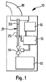
図1は、本発明の実施形態による、エアゾール発生装置10の形で表した液体蒸発装置の具体例を示している。図示されるように、エアゾール発生器10は、液体源12と、バルブ14と、2重平行毛細管路20、30を備える加熱部21と、マウスピース(吸口)18と、任意のセンサ15と、コントローラ16を含んでいる。コントローラ16は、適切な電気接続とバッテリのような補助的装備を含み、その補助的装備はバルブ14、センサ15を動作させ、2重平行毛細管路20、30を加熱するための電気を供給するためのコントローラと協働するものである。動作中、バルブ14はあけられ、ユーザがエアゾール発生器10からエアゾールを吸入するようにすることによってマウスピース18に適用される真空圧力についてのセンサ15による検出前若しくはそれに続いて、液体源12からの必要量の液体が管路20、30に入るようにする。液体が管路20、30に供給されると、コントローラ16は、管路20、30内の液体を揮発させるに充分に毛細管を加熱するための電力量をコントロールする。つまり、コントローラ16は、毛細管を通る電気量をコントロールし、その中の液体を揮発させるのに適切な温度まで液体を加熱する。揮発させられた液体は管路20、30の出口20b、30bから排出され、揮発させられた液体は、マウスピース18にユーザが口をつけることによって吸入されうるエアゾールを形成する。
FIG. 1 shows a specific example of a liquid evaporator represented in the form of an
図1に示されるエアゾール発生器は変形することができ、異なる液体供給配置(装置)を利用することができる。例えば、液体源は、管路20、30に所定量の液体を排出(デリバリー)する排出(デリバリー)バルブを備え、かつ/又は、管路20、30は所定サイズの室(チェンバー)を有し、吸入サイクルの間、揮発されるべき所定量の液体を収容することができる。管路が所定量の液体を収容するチェンバーを有する場合、装置はチェンバーの下流に、液体を満たす間にチェンバー容量を超える液体の流入を防止するための1以上のバルブを備えることができる。必要に応じて、チェンバーはその中の液体を加熱するようにするプレヒータを有することができ、よって、蒸気泡が膨張し、チェンバーから管路20、30に残余液体を送り出すようにする。そのようなプレヒータの詳細は、開示内容が本願で援用され、2000年12月22日に出願の同一出願人による米国特許出願番号09/742,395に示されている。必要に応じて、バルブ(単一又は複数)が省かれ、液体源12がシリンジポンプのような排出(デリバリー)構造を有するようにする。このシリンジポンプは、所定量の液体をチェンバーか、直接管路20、30に供給するものである。加熱部は、管路20、30を定義する毛細管を囲み、管路20、30内の液体を揮発させるようにすることができる。手動動作の場合、例えば、エアゾール発生器10が機械的スイッチ、電気的スイッチ、他の適切な技術によって手動で動作される場合には、センサ15を省くことができる。図1に示されるエアゾール発生器10は、医療(薬用)的使用に有効であるが、装置原理はまた、燃料や臭気材、といったような他の液体を蒸発させるためにも用いることができる。
The aerosol generator shown in FIG. 1 can be modified and different liquid supply arrangements (devices) can be utilized. For example, the liquid source includes a discharge valve for discharging a predetermined amount of liquid to the
本発明の実施形態による2重毛細管エアゾール発生器は、2本の毛細管を持ち、それらは単一の液体源から液体流を受け取り、互いに直列に電気的に接続されている。液体は、一般的に加圧された液体かつ/又は所定量の液体の形であるが、2本の毛細管の入口部を介して入り、その管を出口端又は毛細管の先端部まで流れる。(2本の)毛細管は、各毛細管の入口端に別の電極を供給するか、毛細管の先端部を、例えば銅線のような電導物質、例えば管の溶接部のような金属結合や、そのようなものと電気的に接続することによって、直列に接続される。毛細管は、管を通る電流の流れの結果として加熱され、各管の入口端に入ってくる液体が管内で加熱されて蒸気を形成する。蒸気が毛細管の先端から出て、周辺の大気と接触すると、その蒸気は凝縮されエアゾールを形成する微小の飛沫になる。先端部の2つの管の間の電気接続はまた、温度接続としても役割を果たし、よって第1の毛細管先端部の温度が第2の毛細管先端部の温度と実質的に同一となるのである。単一しんちゅう付け(braze)又は他種類の金属結合が出口端において2つの毛細管を結合するのに用いられる場合、結合部に亘る電気抵抗は低く、出口は毛細管内の蒸発域(zone)よりも低温となる可能性がある。好適な本発明の実施形態では、毛細管先端部間の接続に関する電気抵抗は、幾何学的に、材料の選択によりコントロールされ、出口の温度を調整する。毛細管の先端部が更なる構造に接続され、熱がその構造に伝達される場合の構成では、熱伝達のバランスを取り、所望の先端温度を維持するために、相互接続の電気抵抗は毛細管よりも単位長さ当たり高くすることができる。 A dual capillary aerosol generator according to embodiments of the present invention has two capillaries that receive a liquid stream from a single liquid source and are electrically connected in series with each other. The liquid is generally in the form of a pressurized liquid and / or a predetermined amount of liquid, but enters through the inlets of two capillaries and flows through the tubes to the outlet end or the tip of the capillary. The (two) capillaries either supply a separate electrode to the inlet end of each capillary, or connect the tip of the capillary to a conductive material such as a copper wire, for example a metal bond such as a welded portion of a tube, They are connected in series by electrical connection with such a device. The capillaries are heated as a result of the flow of current through the tubes, and the liquid entering the inlet end of each tube is heated in the tubes to form a vapor. When the vapor exits from the tip of the capillary and comes into contact with the surrounding atmosphere, the vapor is condensed into small droplets that form an aerosol. The electrical connection between the two tubes at the tip also serves as a temperature connection, so that the temperature at the first capillary tip is substantially the same as the temperature at the second capillary tip. When a single braze or other type of metal bond is used to join two capillaries at the exit end, the electrical resistance across the joint is low and the exit is less than the evaporation zone in the capillary. Can also be cold. In a preferred embodiment of the invention, the electrical resistance for the connection between the capillary tips is geometrically controlled by the choice of material and adjusts the outlet temperature. In configurations where the capillary tip is connected to a further structure and heat is transferred to that structure, the electrical resistance of the interconnect is less than that of the capillary to balance the heat transfer and maintain the desired tip temperature. Can also be higher per unit length.
図2で示されるように、液体蒸発装置22は、第1の毛細管20と、それと実質的に平行に配置された第2の毛細管30と、液体源60を含み、液体が両毛細管20、30内を平行に通過するようになっている。液体が入口端20aで第1の毛細管20に、入口端30aで第2の毛細管30にそれぞれ入り、第1の毛細管20の先端部20bと第2の毛細管30の先端部30bとから蒸気として出て行く。第1の電極50は毛細管20の入口端20a付近に接続され、第2の電極52は第2の毛細管の入口端付近に接続される。毛細管20の先端部20b及び毛細管30の先端部30bはまた、短い電極のような導電素子によって電気的に接続される。
As shown in FIG. 2, the
図2で示される構成は、毛細管を介した平行な液流と直列(接続における)の電流を提供する。毛細管の先端部における電気接続54はまた、温度接続を提供し、毛細管20の先端部20bが毛細管30の先端部30bと同じ温度に保たれるようになっている。毛細管を通る電流は毛細管を加熱し、そして、その毛細管に沿った温度特性は、管を亘って印加される電圧量及び管中の液体流速によって少なくとも一部が決定されている。
The configuration shown in FIG. 2 provides current in series (in connection) with parallel liquid flow through the capillary. The
毛細管20の入口部20aと毛細管30の入口部30bで入る液体は、平行な毛細管内を進むに従って加熱される。充分な熱が管内を進む液体に加えられ、毛細管先端部20b及び30bから液体が出る際にその液体を蒸発させ、蒸発状態に保たれる。先端部20bと30bは、電気的及び温度的接続54の結果として実質的に同一温度に保つことができるので、電気接続54の熱伝導による熱損失の可能性が無く、高品質のエアゾールを発生させるのに必要な温度に先端部20b及び30bを保つことことがより容易である。
The liquid that enters the inlet 20a of the capillary 20 and the
2重毛細管構成は、毛細管内の様々な液体流速を許容するように設計され、高エネルギー効率であり、コンパクトな構成を提供する。吸入器の応用例では、毛細管の加熱領域(zone)は、5から40mmで、より好ましくは10から25mmであり、管の内径は0.1から0.5mmで、より好ましくは0.2から0.4mmとすることができる。吸入器で毛細管加熱を実現する際には、毛細管構成は好ましくは、大気や毛細管から排出される蒸気から断熱され、かつ/又は隔離されるようにする。例えば、ステンレス鋼箔などの断熱材や金属箔の主要部は、マウスピース内で毛細管端部を支持するために用いられ、よって毛細管から出る蒸気は金属箔の上側にある毛細管の外面に接触しないようになっている。 The dual capillary configuration is designed to allow for various liquid flow rates within the capillary and is highly energy efficient and provides a compact configuration. For inhaler applications, the capillary heating zone is from 5 to 40 mm, more preferably from 10 to 25 mm, and the inner diameter of the tube is from 0.1 to 0.5 mm, more preferably from 0.2. It can be 0.4 mm. In achieving capillary heating with an inhaler, the capillary configuration is preferably insulated and / or isolated from the atmosphere and vapors exhausted from the capillary. For example, the main part of the insulation or metal foil, such as stainless steel foil, is used to support the capillary end within the mouthpiece, so that the vapor coming from the capillary does not contact the outer surface of the capillary above the metal foil It is like that.
本発明は、好適な実施形態に従って図示され、説明されたが、特許請求の範囲で述べる本発明の趣旨から逸脱しない限りにおいて、変化や変更を加えることは本発明の範囲内のことと認識される。 While the invention has been illustrated and described in accordance with preferred embodiments, it is recognized that changes and modifications are within the scope of the invention without departing from the spirit of the invention as set forth in the appended claims. The
本出願に係る発明は、単なる一例である装置及び方法の好適な実施形態および添付図面を参照して、より詳細に説明される。図面については以下の通りである。
Claims (8)
電源と、
前記電源によって電気的に加熱される加熱部であって、前記液体源に導通した入口部を有する第1及び第2の毛細管を含み、これら毛細管で液体を蒸発させるように動作する加熱部と、
電流を前記第1の毛細管に供給し、電流が前記第1の毛細管の少なくとも一部を通るようにする第1の電極と、
前記毛細管を接続し、前記第1の毛細管に供給される電流が前記第2の毛細管の少なくとも一部を通るようにする電気接続部と、
前記第2の毛細管に電気的に接続されるように、前記第1の毛細管と前記電気接続部と前記第2の毛細管と、が前記電源に直列に電気接続されることを特徴とする2重毛細管液体蒸発装置。At least one liquid source;
Power supply,
A heating unit that is electrically heated by the power source, the heating unit including first and second capillaries having an inlet connected to the liquid source, and operating to evaporate the liquid in the capillaries;
A first electrode for supplying current to the first capillary and allowing the current to pass through at least a portion of the first capillary;
An electrical connection for connecting the capillaries and allowing current supplied to the first capillaries to pass through at least a portion of the second capillaries;
To so that is electrically connected to the second capillary tube, 2 and the first capillary tube and the electrical connecting portion and the second capillary tube, it is characterized in that it is electrically connected in series with said power supply duplex Capillary liquid evaporator.
前記第1及び第2の毛細管を相互接続している電気接続部を通して、前記第1及び第2の毛細管に電源からの電流を通すために、前記第1の毛細管と前記電気接続部と前記第2の毛細管と、が前記電源に直列に電気接続されており、前記第1及び第2の毛細管を加熱し、前記電流は前記各毛細管を加熱するのに効果的であり、管内の前記液体は揮発させられ、蒸気として毛細管から排出される工程と、
を備えることを特徴とする液体蒸発方法。Supplying liquid from a liquid source to the first and second capillaries;
In order to pass current from a power source through the electrical connection interconnecting the first and second capillaries to the first and second capillaries, the first capillary, the electrical connection, and the first capillary and 2 of the capillary tube are electrically connected in series to said power source, and heating the first and second capillary tube, the current is effective to heat the respective capillary, the liquid in the tube Vaporized and discharged from the capillary as a vapor;
A liquid evaporation method comprising:
前記電源によって電気的に加熱される加熱部であって、入口部を有する第1及び第2の毛細管を含み、これら毛細管で液体を蒸発させるように動作する加熱部と、
電流を前記第1の毛細管に供給し、電流が前記第1の毛細管の少なくとも一部を通るようにする第1の電極と、
前記各毛細管を接続し、前記第1の毛細管に供給される電流が前記第2の毛細管の少なくとも一部を通るようにする電気接続部と、
前記第2の毛細管に電気的に接続するために、前記第1の毛細管と前記電気接続部と前記第2の毛細管と、を前記電源に直列に電気接続する第2の電極と、
を備えることを特徴とする2重毛細管液体蒸発装置。Power supply,
A heating unit that is electrically heated by the power source, comprising first and second capillaries having an inlet, and operating to evaporate liquid in the capillaries;
A first electrode for supplying current to the first capillary and allowing the current to pass through at least a portion of the first capillary;
An electrical connection for connecting each of the capillaries and allowing current supplied to the first capillary to pass through at least a portion of the second capillary;
A second electrode for electrically connecting the first capillary, the electrical connection, and the second capillary in series with the power source to electrically connect to the second capillary ;
A double capillary liquid evaporator.
第1及び第2の毛細管に液体を供給する工程と、
電源から電流を、前記第1の毛細管に通し、前記第1及び第2の毛細管を相互接続している電気接続部に通すために、前記第1の毛細管と前記電気接続部と前記第2の毛細管と、が前記電源に直列に電気接続されており、前記第1及び第2の毛細管を加熱し、
前記電流は毛細管を加熱するのに効果的であり、管内の前記液体は揮発させられ、蒸気として毛細管から排出される工程と、
を備えることを特徴とする液体蒸発方法。A liquid evaporation method in a liquid evaporation apparatus,
Supplying liquid to the first and second capillaries;
In order to pass current from a power source through the first capillary and through the electrical connection interconnecting the first and second capillaries , the first capillary, the electrical connection, and the second capillary A capillary is electrically connected in series with the power source, heating the first and second capillaries;
The current is effective to heat the capillary, and the liquid in the tube is volatilized and discharged from the capillary as vapor;
A liquid evaporation method comprising:
ことを特徴とする請求項6に記載の液体蒸発方法。(A) The power source includes a battery, and the current is a direct current coming in series from the battery, passes through the first capillary, passes through the electrical connection, passes through the second capillary, and further includes the battery. Returning to (b) the capillary is composed of a heat resistant material, the liquid is heated as a result of resistance to heat the capillary, (c) the electrical connection is located at both outlet ends of the capillary, The outlet ends are heated to substantially the same temperature while heating the capillary; (d) the capillaries are parallel to each other, made of the same material, have the same length and the same inner diameter; (E) the capillaries are in communication with the same liquid source; (f) the liquid comprises a liquid of medicinal substance; the vapor exiting the capillary forms an aerosol containing the medicinal substance and / or (g ) Said first and second Capillary has an outlet portion very close position, the steam exiting the outlet portion condenses the atmosphere,
The liquid evaporation method according to claim 6 .
Applications Claiming Priority (2)
| Application Number | Priority Date | Filing Date | Title |
|---|---|---|---|
| US09/956,966 US6568390B2 (en) | 2001-09-21 | 2001-09-21 | Dual capillary fluid vaporizing device |
| PCT/US2002/029413 WO2003027779A2 (en) | 2001-09-21 | 2002-09-18 | Dual capillary fluid vaporizing device |
Publications (3)
| Publication Number | Publication Date |
|---|---|
| JP2005503875A JP2005503875A (en) | 2005-02-10 |
| JP2005503875A5 JP2005503875A5 (en) | 2005-10-27 |
| JP4351529B2 true JP4351529B2 (en) | 2009-10-28 |
Family
ID=25498910
Family Applications (1)
| Application Number | Title | Priority Date | Filing Date |
|---|---|---|---|
| JP2003531262A Expired - Lifetime JP4351529B2 (en) | 2001-09-21 | 2002-09-18 | Double capillary liquid evaporator |
Country Status (7)
| Country | Link |
|---|---|
| US (2) | US6568390B2 (en) |
| EP (1) | EP1428080B1 (en) |
| JP (1) | JP4351529B2 (en) |
| AU (1) | AU2002326934A1 (en) |
| ES (1) | ES2434827T3 (en) |
| PT (1) | PT1428080E (en) |
| WO (1) | WO2003027779A2 (en) |
Families Citing this family (111)
| Publication number | Priority date | Publication date | Assignee | Title |
|---|---|---|---|---|
| US9006175B2 (en) | 1999-06-29 | 2015-04-14 | Mannkind Corporation | Potentiation of glucose elimination |
| US7458374B2 (en) | 2002-05-13 | 2008-12-02 | Alexza Pharmaceuticals, Inc. | Method and apparatus for vaporizing a compound |
| US7645442B2 (en) | 2001-05-24 | 2010-01-12 | Alexza Pharmaceuticals, Inc. | Rapid-heating drug delivery article and method of use |
| US20030051728A1 (en) | 2001-06-05 | 2003-03-20 | Lloyd Peter M. | Method and device for delivering a physiologically active compound |
| PT2495004E (en) * | 2001-07-31 | 2014-07-24 | Philip Morris Products S A S | Method and apparatus for generating a volatilized material |
| US6568390B2 (en) * | 2001-09-21 | 2003-05-27 | Chrysalis Technologies Incorporated | Dual capillary fluid vaporizing device |
| WO2003080149A2 (en) | 2002-03-20 | 2003-10-02 | Mannkind Corporation | Inhalation apparatus |
| US6820598B2 (en) | 2002-03-22 | 2004-11-23 | Chrysalis Technologies Incorporated | Capillary fuel injector with metering valve for an internal combustion engine |
| US7357124B2 (en) * | 2002-05-10 | 2008-04-15 | Philip Morris Usa Inc. | Multiple capillary fuel injector for an internal combustion engine |
| US6854461B2 (en) * | 2002-05-10 | 2005-02-15 | Philip Morris Usa Inc. | Aerosol generator for drug formulation and methods of generating aerosol |
| ES2357566T3 (en) * | 2002-09-06 | 2011-04-27 | Philip Morris Usa Inc. | AEROSOL GENERATING DEVICES AND METHODS FOR GENERATING AEROSOLS WITH CONTROLLED PARTICLE SIZES. |
| ES2400706T3 (en) * | 2002-09-06 | 2013-04-11 | Philip Morris Usa Inc. | Aerosol generation device and method of use |
| US7040314B2 (en) * | 2002-09-06 | 2006-05-09 | Philip Morris Usa Inc. | Aerosol generating devices and methods for generating aerosols suitable for forming propellant-free aerosols |
| US6772757B2 (en) * | 2002-10-25 | 2004-08-10 | Chrysalis Technologies Incorporated | Concentric controlled temperature profile fluid vaporizing device |
| US7913688B2 (en) | 2002-11-27 | 2011-03-29 | Alexza Pharmaceuticals, Inc. | Inhalation device for producing a drug aerosol |
| AU2003297087B2 (en) * | 2003-02-04 | 2009-06-11 | Philip Morris Products S.A. | Aerosol formulations and aerosol delivery of buspirone, buprenorphine, triazolam, cyclobenzaprine and zolpidem |
| CN100381083C (en) | 2003-04-29 | 2008-04-16 | 韩力 | Electronic nonflammable spraying cigarette |
| US20040223918A1 (en) * | 2003-05-07 | 2004-11-11 | Chrysalis Technologies Incorporated | Aerosolization of cromolyn sodium using a capillary aerosol generator |
| ATE510174T1 (en) * | 2003-05-21 | 2011-06-15 | Alexza Pharmaceuticals Inc | IMPACT LIT INDEPENDENT HEATING UNIT |
| WO2004112799A1 (en) * | 2003-06-13 | 2004-12-29 | Chrysalis Technologies Incorporated | Methods and apparatus for producing nanoscale particles |
| US20040265519A1 (en) * | 2003-06-27 | 2004-12-30 | Pellizzari Roberto O. | Fabrication of fluid delivery components |
| US7004138B2 (en) | 2003-07-15 | 2006-02-28 | Eaton Corporation | Pressure pulse communication in an engine intake manifold |
| US7367334B2 (en) * | 2003-08-27 | 2008-05-06 | Philip Morris Usa Inc. | Fluid vaporizing device having controlled temperature profile heater/capillary tube |
| WO2005037949A2 (en) * | 2003-10-07 | 2005-04-28 | Chrysalis Technologies Incorporated | Aerosol formulations of butalbital, lorazepam, ipratropium, baclofen, morphine and scopolamine |
| US7337768B2 (en) * | 2004-05-07 | 2008-03-04 | Philip Morris Usa Inc. | Multiple capillary fuel injector for an internal combustion engine |
| US7402777B2 (en) | 2004-05-20 | 2008-07-22 | Alexza Pharmaceuticals, Inc. | Stable initiator compositions and igniters |
| US7540286B2 (en) | 2004-06-03 | 2009-06-02 | Alexza Pharmaceuticals, Inc. | Multiple dose condensation aerosol devices and methods of forming condensation aerosols |
| JP5078014B2 (en) | 2004-08-20 | 2012-11-21 | マンカインド コーポレイション | Catalytic reaction of diketopiperazine synthesis. |
| MX2007002189A (en) | 2004-08-23 | 2008-01-11 | Mannkind Corp | Diketopiperazine salts, diketomorpholine salts or diketodioxane salts for drug delivery. |
| US7167776B2 (en) * | 2004-09-02 | 2007-01-23 | Philip Morris Usa Inc. | Method and system for controlling a vapor generator |
| US20060102175A1 (en) * | 2004-11-18 | 2006-05-18 | Nelson Stephen G | Inhaler |
| JP5059740B2 (en) * | 2005-02-09 | 2012-10-31 | エス3アイ, エル エル シィ | Method and system for detecting, classifying and identifying particles |
| US7186958B1 (en) * | 2005-09-01 | 2007-03-06 | Zhao Wei, Llc | Inhaler |
| US7803404B2 (en) | 2005-09-14 | 2010-09-28 | Mannkind Corporation | Method of drug formulation based on increasing the affinity of active agents for crystalline microparticle surfaces |
| FR2891435B1 (en) * | 2005-09-23 | 2007-11-09 | Bull Sa Sa | HOLDING SYSTEM IN POSITION OF A THREE-PART ASSEMBLY PROVIDING A PREDETERMINAL COMPRESSION EFFORT ON THE INTERMEDIATE PART |
| WO2007046395A1 (en) * | 2005-10-18 | 2007-04-26 | Canon Kabushiki Kaisha | Liquid ejection device and ejection method |
| US20100142934A1 (en) * | 2005-12-01 | 2010-06-10 | Vapore, Inc. | Advanced Capillary Force Vaporizers |
| US7494344B2 (en) * | 2005-12-29 | 2009-02-24 | Molex Incorporated | Heating element connector assembly with press-fit terminals |
| US9604016B2 (en) * | 2006-01-31 | 2017-03-28 | Philip Morris Usa Inc. | Bent capillary tube aerosol generator |
| IN2015DN00888A (en) | 2006-02-22 | 2015-07-10 | Mannkind Corp | |
| EP2037999B1 (en) | 2006-07-07 | 2016-12-28 | Proteus Digital Health, Inc. | Smart parenteral administration system |
| WO2008027755A2 (en) * | 2006-08-30 | 2008-03-06 | Novo Nordisk A/S | Use of electrostatics in an aerosol device |
| US7518123B2 (en) * | 2006-09-25 | 2009-04-14 | Philip Morris Usa Inc. | Heat capacitor for capillary aerosol generator |
| US7513781B2 (en) | 2006-12-27 | 2009-04-07 | Molex Incorporated | Heating element connector assembly with insert molded strips |
| US9061300B2 (en) * | 2006-12-29 | 2015-06-23 | Philip Morris Usa Inc. | Bent capillary tube aerosol generator |
| WO2008112661A2 (en) | 2007-03-09 | 2008-09-18 | Alexza Pharmaceuticals, Inc. | Heating unit for use in a drug delivery device |
| US8442390B2 (en) | 2007-08-29 | 2013-05-14 | Philip Morris Usa Inc. | Pulsed aerosol generation |
| US8052127B2 (en) | 2007-10-19 | 2011-11-08 | Philip Morris Usa Inc. | Respiratory humidification system |
| JP5243548B2 (en) | 2007-10-25 | 2013-07-24 | プロテウス デジタル ヘルス, インコーポレイテッド | Fluid communication port for information systems |
| US8419638B2 (en) | 2007-11-19 | 2013-04-16 | Proteus Digital Health, Inc. | Body-associated fluid transport structure evaluation devices |
| ES2394589T3 (en) | 2007-12-14 | 2013-02-04 | Aerodesigns, Inc | Supply of food products transformable in aerosol |
| US8201752B2 (en) * | 2008-03-10 | 2012-06-19 | Vapore, Inc. | Low energy vaporization of liquids: apparatus and methods |
| EP2100525A1 (en) * | 2008-03-14 | 2009-09-16 | Philip Morris Products S.A. | Electrically heated aerosol generating system and method |
| EP2113178A1 (en) | 2008-04-30 | 2009-11-04 | Philip Morris Products S.A. | An electrically heated smoking system having a liquid storage portion |
| KR101933816B1 (en) | 2008-06-13 | 2019-03-29 | 맨카인드 코포레이션 | A dry powder inhaler and system for drug delivery |
| US8485180B2 (en) | 2008-06-13 | 2013-07-16 | Mannkind Corporation | Dry powder drug delivery system |
| WO2009155581A1 (en) | 2008-06-20 | 2009-12-23 | Mannkind Corporation | An interactive apparatus and method for real-time profiling of inhalation efforts |
| TWI494123B (en) | 2008-08-11 | 2015-08-01 | Mannkind Corp | Use of ultrarapid acting insulin |
| US8314106B2 (en) | 2008-12-29 | 2012-11-20 | Mannkind Corporation | Substituted diketopiperazine analogs for use as drug delivery agents |
| PL2405963T3 (en) | 2009-03-11 | 2014-04-30 | Mannkind Corp | Apparatus, system and method for measuring resistance of an inhaler |
| BRPI1013154B1 (en) | 2009-06-12 | 2020-04-07 | Mannkind Corp | MICROPARTICLES OF DICETOPIPERAZINE WITH SPECIFIC SURFACE AREAS DEFINED, DRY POWDER UNDERSTANDING THE REFERRED MICROPARTICLES, METHOD FOR FORMATION OF THE REFERENCESMICROPARTICLES AND THE FORMATION OF MICROPARTYSTEMS |
| KR101761433B1 (en) | 2009-10-09 | 2017-07-25 | 필립모리스 프로덕츠 에스.에이. | Aerosol generator including multi-component wick |
| AU2010308089B2 (en) | 2009-10-13 | 2015-05-21 | Philip Morris Products S.A. | Air freshening device |
| EP2319334A1 (en) | 2009-10-27 | 2011-05-11 | Philip Morris Products S.A. | A smoking system having a liquid storage portion |
| CA2778698A1 (en) | 2009-11-03 | 2011-05-12 | Mannkind Corporation | An apparatus and method for simulating inhalation efforts |
| WO2011061478A1 (en) | 2009-11-18 | 2011-05-26 | Reckitt Benckiser Llc | Lavatory treatment device and method |
| WO2011061480A1 (en) | 2009-11-18 | 2011-05-26 | Reckitt Benckiser Llc | Surface treatment device and method |
| JP5841951B2 (en) | 2010-02-01 | 2016-01-13 | プロテウス デジタル ヘルス, インコーポレイテッド | Data collection system |
| SG189763A1 (en) | 2010-02-01 | 2013-05-31 | Proteus Digital Health Inc | Two-wrist data gathering system |
| MX359281B (en) | 2010-06-21 | 2018-09-21 | Mannkind Corp | Dry powder drug delivery system and methods. |
| EP2641490A4 (en) * | 2010-11-19 | 2017-06-21 | Kimree Hi-Tech Inc | Electronic cigarette, electronic cigarette flare and atomizer thereof |
| WO2012129812A1 (en) * | 2011-03-31 | 2012-10-04 | 深圳市康泰尔电子有限公司 | Electronic cigarette |
| MX353285B (en) | 2011-04-01 | 2018-01-05 | Mannkind Corp | Blister package for pharmaceutical cartridges. |
| WO2012174472A1 (en) | 2011-06-17 | 2012-12-20 | Mannkind Corporation | High capacity diketopiperazine microparticles |
| IN2014DN03093A (en) | 2011-10-24 | 2015-05-15 | Mannkind Corp | |
| US9282772B2 (en) | 2012-01-31 | 2016-03-15 | Altria Client Services Llc | Electronic vaping device |
| EP2816913B1 (en) | 2012-02-22 | 2019-01-09 | Altria Client Services LLC | Electronic smoking article and improved heater element |
| CA2864832A1 (en) | 2012-02-22 | 2013-08-29 | Altria Client Services Inc. | Electronic smoking article |
| SG10201605800UA (en) | 2012-07-12 | 2016-09-29 | Mannkind Corp | Dry powder drug delivery system and methods |
| US9713687B2 (en) | 2012-08-21 | 2017-07-25 | Philip Morris Usa Inc. | Ventilator aerosol delivery system with transition adapter for introducing carrier gas |
| RU2602962C2 (en) * | 2012-08-31 | 2016-11-20 | Кимри Хай-Тек Инк. | Electronic cigarette |
| WO2014066856A1 (en) | 2012-10-26 | 2014-05-01 | Mannkind Corporation | Inhalable influenza vaccine compositions and methods |
| US10034988B2 (en) | 2012-11-28 | 2018-07-31 | Fontem Holdings I B.V. | Methods and devices for compound delivery |
| USD691765S1 (en) | 2013-01-14 | 2013-10-15 | Altria Client Services Inc. | Electronic smoking article |
| USD695449S1 (en) | 2013-01-14 | 2013-12-10 | Altria Client Services Inc. | Electronic smoking article |
| USD691766S1 (en) | 2013-01-14 | 2013-10-15 | Altria Client Services Inc. | Mouthpiece of a smoking article |
| USD841231S1 (en) | 2013-01-14 | 2019-02-19 | Altria Client Services, Llc | Electronic vaping device mouthpiece |
| USD849993S1 (en) | 2013-01-14 | 2019-05-28 | Altria Client Services | Electronic smoking article |
| US20140261488A1 (en) * | 2013-03-15 | 2014-09-18 | Altria Client Services Inc. | Electronic smoking article |
| KR102499439B1 (en) | 2013-03-15 | 2023-02-13 | 맨카인드 코포레이션 | Microcrystalline diketopiperazine compositions and methods |
| CA2918369C (en) | 2013-07-18 | 2021-06-29 | Mannkind Corporation | Heat-stable dry powder pharmaceutical compositions and methods |
| WO2015021064A1 (en) | 2013-08-05 | 2015-02-12 | Mannkind Corporation | Insufflation apparatus and methods |
| US10194693B2 (en) | 2013-09-20 | 2019-02-05 | Fontem Holdings 1 B.V. | Aerosol generating device |
| BR302014001648S1 (en) | 2013-10-14 | 2015-06-09 | Altria Client Services Inc | Smoke Applied Configuration |
| US10307464B2 (en) | 2014-03-28 | 2019-06-04 | Mannkind Corporation | Use of ultrarapid acting insulin |
| RU2723335C2 (en) * | 2014-06-30 | 2020-06-09 | Сике Медикал Лтд. | Dose cartridge for inhaler |
| US10561806B2 (en) | 2014-10-02 | 2020-02-18 | Mannkind Corporation | Mouthpiece cover for an inhaler |
| WO2016050244A1 (en) * | 2014-10-03 | 2016-04-07 | Fertin Pharma A/S | Electronic nicotine delivery system |
| US20210172650A1 (en) * | 2015-02-05 | 2021-06-10 | Giorgio TORCHIO | Capillary Proximity Heater |
| DK3254034T3 (en) * | 2015-02-05 | 2022-04-04 | Giorgio Torchio | High energy-saving capillary proximity heater located upstream of a microfiltration apparatus to eliminate limescale particles present in liquids and downstream of a nozzle or closed circuit |
| EP3066940B1 (en) * | 2015-03-13 | 2020-05-06 | Fontem Holdings 1 B.V. | Aerosol generating component for an electronic smoking device and electronic smoking device |
| US10433580B2 (en) | 2016-03-03 | 2019-10-08 | Altria Client Services Llc | Methods to add menthol, botanic materials, and/or non-botanic materials to a cartridge, and/or an electronic vaping device including the cartridge |
| US10455863B2 (en) | 2016-03-03 | 2019-10-29 | Altria Client Services Llc | Cartridge for electronic vaping device |
| US10368580B2 (en) | 2016-03-08 | 2019-08-06 | Altria Client Services Llc | Combined cartridge for electronic vaping device |
| US10357060B2 (en) | 2016-03-11 | 2019-07-23 | Altria Client Services Llc | E-vaping device cartridge holder |
| US10368581B2 (en) | 2016-03-11 | 2019-08-06 | Altria Client Services Llc | Multiple dispersion generator e-vaping device |
| US9861102B2 (en) | 2016-05-26 | 2018-01-09 | Markesbery Blue Pearl LLC | Methods for disinfection |
| US11425911B2 (en) | 2017-05-25 | 2022-08-30 | Markesbery Blue Pearl LLC | Method for disinfection of items and spaces |
| US10881140B2 (en) * | 2016-06-20 | 2021-01-05 | Altria Client Services Llc | Vaporiser assembly for an aerosol-generating system |
| CN108308721B (en) * | 2018-04-17 | 2022-07-19 | 深圳市卓力能技术有限公司 | Many oil tanks electron cigarette |
| US11607506B2 (en) | 2019-02-22 | 2023-03-21 | Altria Client Services Llc | Electronic dispersion device |
Family Cites Families (207)
| Publication number | Priority date | Publication date | Assignee | Title |
|---|---|---|---|---|
| BE354004A (en) | ||||
| FR667979A (en) | 1929-01-24 | 1929-10-25 | Heated liquid medical gasifier with pneumatically balanced level | |
| DE1036470C2 (en) | 1956-09-18 | 1959-01-29 | Bergbau Berufsgenossenschaft | Method and device for generating a common salt aerosol |
| US2896856A (en) | 1956-12-21 | 1959-07-28 | Licencia Talalmanyokat | Vaporizer for diesel engines |
| US3084698A (en) | 1960-04-01 | 1963-04-09 | Marvin M Smith | Instrument for cooling smoke |
| US3162324A (en) | 1961-11-22 | 1964-12-22 | Robertshaw Controls Co | Pneumatic dispenser |
| NL297349A (en) | 1962-08-31 | |||
| US3431393A (en) | 1965-09-07 | 1969-03-04 | Dainippon Jochugiku Kk | Apparatus for vaporizing chemicals and perfumes by heating |
| US3486663A (en) | 1967-11-16 | 1969-12-30 | Frederick Harold Humphrey | Elastomeric pump and check-valve |
| DE1813993C3 (en) | 1968-12-11 | 1974-01-24 | Paul Ritzau Pari-Werk Kg, 8135 Soecking | Device for atomizing and atomizing liquid or powdery substances |
| US3716416A (en) | 1971-05-20 | 1973-02-13 | Engelhard Min & Chem | Fuel metering device for fuel cell |
| US3750961A (en) | 1971-07-16 | 1973-08-07 | N Franz | Very high velocity fluid jet nozzles and methods of making same |
| BE788194A (en) | 1971-08-31 | 1973-02-28 | Thomae Gmbh Dr K | DEVICE FOR THE ADMINISTRATION OF MECHANICALLY DOSE QUANTITIES OF LIQUID OR SOLUTION MEDICINAL PRODUCTS |
| US3859398A (en) | 1972-10-05 | 1975-01-07 | Hudson Oxygen Therapy Sales Co | Outboard heating device |
| US3902635A (en) | 1973-03-05 | 1975-09-02 | Walter J Jinotti | Fluid dispensing apparatus |
| US4042153A (en) | 1973-03-14 | 1977-08-16 | Standard Oil Company | Liquid dropping device |
| US3847304A (en) | 1973-08-13 | 1974-11-12 | M Cohen | Bag-type fluid and paste dispenser |
| US3967001A (en) | 1973-11-01 | 1976-06-29 | The United States Of America As Represented By The Secretary Of The Army | Process of preparing a secondary electron emissive coating on the interior walls of a microchannel plate |
| US3987941A (en) | 1973-12-14 | 1976-10-26 | Blessing Alfred V | Preserving container for liquid food substances |
| US3903883A (en) | 1974-04-17 | 1975-09-09 | Respiratory Care | Variable aerosol heater with automatic temperature control |
| US3904083A (en) | 1974-04-19 | 1975-09-09 | Gen Electric | Self-sealing viscous material dispenser loading apparatus |
| US3995371A (en) | 1974-10-10 | 1976-12-07 | The Curators Of The University Of Missouri | Electroless plating method for treating teeth |
| US4077542A (en) | 1974-12-02 | 1978-03-07 | Petterson Tor H | Unattended aerosol dispenser |
| US3993246A (en) | 1975-06-19 | 1976-11-23 | Erb Elisha | Nebulizer and method |
| US4060082A (en) | 1976-08-16 | 1977-11-29 | Mpl, Inc. | Dual-ingredient medication dispenser |
| US4161281A (en) | 1976-08-30 | 1979-07-17 | Erb Elisha | Pneumatic nebulizer and method |
| NL165639C (en) | 1977-03-02 | 1981-05-15 | Evert Jacob Sybren Bron | PIPE FOR CIGARETTES, CIGARS AND OTHER TOBACCO APPLIANCES WITH AN SMOOTH THREADED IN THE SMOKE. |
| US4162501A (en) | 1977-08-08 | 1979-07-24 | Silonics, Inc. | Ink supply system for an ink jet printer |
| US4258073A (en) | 1978-03-02 | 1981-03-24 | Payne John M | Taking of finger prints |
| US4231492A (en) | 1978-03-14 | 1980-11-04 | Oatey Co. | Apparatus and method for dispensing putty-like material |
| US4261356A (en) | 1978-10-23 | 1981-04-14 | Baxter Travenol Laboratories, Inc. | Method and apparatus for controlling the dispensing of fluid |
| US4289003A (en) | 1979-05-10 | 1981-09-15 | Yang Tayhugh L | Key holder |
| GB2050303B (en) | 1979-05-21 | 1983-03-02 | Rhen Beteiligung Finanz | Dispensing valve |
| US4291838A (en) | 1979-12-26 | 1981-09-29 | C. R. Bard, Inc. | Nebulizer and associated heater |
| US4471892A (en) | 1980-02-11 | 1984-09-18 | Fabricated Metals, Inc. | Material container having a flexible follower |
| US4259409A (en) | 1980-03-06 | 1981-03-31 | Ses, Incorporated | Electroless plating process for glass or ceramic bodies and product |
| US4303083A (en) | 1980-10-10 | 1981-12-01 | Burruss Jr Robert P | Device for evaporation and inhalation of volatile compounds and medications |
| US4383171A (en) | 1980-11-17 | 1983-05-10 | The United States Of America As Represented By The Administrator Of The National Aeronautics And Space Administration | Particle analyzing method and apparatus |
| US4391308A (en) | 1981-04-16 | 1983-07-05 | Steiner Corporation | Soap dispensing system |
| US4395303A (en) | 1981-04-22 | 1983-07-26 | Masco Corporation | Method of manufacturing thin-walled corrosion resistant metallic objects |
| FI79651C (en) | 1982-10-08 | 1990-02-12 | Glaxo Group Ltd | Dosing device for medicine |
| US4512341A (en) | 1982-11-22 | 1985-04-23 | Lester Victor E | Nebulizer with capillary feed |
| US4682010A (en) | 1983-03-07 | 1987-07-21 | Safeway Products, Inc. | In-line electric heater for an aerosol delivery system |
| US4730111A (en) | 1983-08-30 | 1988-03-08 | Research Corporation | Ion vapor source for mass spectrometry of liquids |
| US4649911A (en) | 1983-09-08 | 1987-03-17 | Baylor College Of Medicine | Small particle aerosol generator for treatment of respiratory disease including the lungs |
| US4575609A (en) | 1984-03-06 | 1986-03-11 | The United States Of America As Represented By The United States Department Of Energy | Concentric micro-nebulizer for direct sample insertion |
| IT1196142B (en) | 1984-06-11 | 1988-11-10 | Sicor Spa | PROCEDURE FOR THE PREPARATION OF 16.17-ACETALS OF PREGNANIC DERIVATIVES AND NEW COMPOUNDS OBTAINED |
| US4762995A (en) | 1984-06-22 | 1988-08-09 | Georgia Tech Research Corporation | Monodisperse aerosol generator |
| EP0181092B1 (en) | 1984-10-04 | 1993-01-13 | I J & L A TETLEY MANUFACTURING PTY LTD | Apparatus for producing a diagnostic gas composition |
| US4744932A (en) | 1985-05-31 | 1988-05-17 | Celanese Corporation | Process for forming a skinless hollow fiber of a cellulose ester |
| US4700657A (en) | 1985-07-10 | 1987-10-20 | Print-Lock Corporation | Fingerprinting system incorporating a spray container and a portable vapor tank |
| GR861995B (en) | 1985-07-30 | 1986-11-04 | Glaxo Group Ltd | Devices for administering medicaments to patients |
| US5133343A (en) | 1985-08-09 | 1992-07-28 | Johnson Iv John J | Apparatus for supporting an inhaler |
| JPS62153370A (en) | 1985-12-27 | 1987-07-08 | Alpha Giken:Kk | 2-cyanoacrylate composition |
| GB8604328D0 (en) | 1986-02-21 | 1986-03-26 | Ici Plc | Producing spray of droplets of liquid |
| US4837260A (en) | 1986-05-23 | 1989-06-06 | Toagosei Chemical Industry Co., Ltd. | Cyanoacrylate compositions |
| US4926852B1 (en) | 1986-06-23 | 1995-05-23 | Univ Johns Hopkins | Medication delivery system phase one |
| US4790305A (en) | 1986-06-23 | 1988-12-13 | The Johns Hopkins University | Medication delivery system |
| US4776515A (en) | 1986-08-08 | 1988-10-11 | Froughieh Michalchik | Electrodynamic aerosol generator |
| DE3627222A1 (en) | 1986-08-11 | 1988-02-18 | Siemens Ag | ULTRASONIC POCKET SPRAYER |
| US4735217A (en) | 1986-08-21 | 1988-04-05 | The Procter & Gamble Company | Dosing device to provide vaporized medicament to the lungs as a fine aerosol |
| US4819834A (en) | 1986-09-09 | 1989-04-11 | Minnesota Mining And Manufacturing Company | Apparatus and methods for delivering a predetermined amount of a pressurized fluid |
| GB8713645D0 (en) | 1987-06-11 | 1987-07-15 | Imp Tobacco Ltd | Smoking device |
| US5322057A (en) | 1987-07-08 | 1994-06-21 | Vortran Medical Technology, Inc. | Intermittent signal actuated nebulizer synchronized to operate in the exhalation phase, and its method of use |
| US4871115A (en) | 1987-08-24 | 1989-10-03 | Hessey B Russell | Smoke generating apparatus |
| US4935624A (en) | 1987-09-30 | 1990-06-19 | Cornell Research Foundation, Inc. | Thermal-assisted electrospray interface (TAESI) for LC/MS |
| US5063921A (en) | 1987-11-12 | 1991-11-12 | Cimco, Inc. | Nebulizer heater |
| US5259370A (en) | 1987-11-12 | 1993-11-09 | Cimco, Inc. | Nebulizer heater |
| US4819625A (en) | 1987-11-12 | 1989-04-11 | Cimco, Inc. | Nebulizer heater |
| CH675216A5 (en) | 1987-11-30 | 1990-09-14 | Alphasem Ag | |
| US4911157A (en) | 1988-01-07 | 1990-03-27 | Pegasus Research Corporation | Self-regulating, heated nebulizer system |
| US5021802A (en) | 1988-02-19 | 1991-06-04 | Dataproducts Corporation | Thermally reversible sol-gel phase change ink or bubble jet ink |
| US4871623A (en) | 1988-02-19 | 1989-10-03 | Minnesota Mining And Manufacturing Company | Sheet-member containing a plurality of elongated enclosed electrodeposited channels and method |
| EP0358114A3 (en) | 1988-09-08 | 1990-11-14 | R.J. Reynolds Tobacco Company | Aerosol delivery articles utilizing electrical energy |
| US4922901A (en) | 1988-09-08 | 1990-05-08 | R. J. Reynolds Tobacco Company | Drug delivery articles utilizing electrical energy |
| US4947875A (en) | 1988-09-08 | 1990-08-14 | R. J. Reynolds Tobacco Company | Flavor delivery articles utilizing electrical energy |
| US4992206A (en) | 1988-11-01 | 1991-02-12 | Lowndes Engineering Co., Inc. | Aerosol generator apparatus and method of use |
| US4917119A (en) * | 1988-11-30 | 1990-04-17 | R. J. Reynolds Tobacco Company | Drug delivery article |
| EP0373237A1 (en) | 1988-12-13 | 1990-06-20 | Siemens Aktiengesellschaft | Pocket inhaler device |
| DE3908161A1 (en) | 1989-03-13 | 1990-09-27 | Bat Cigarettenfab Gmbh | Smokable article |
| US4982097A (en) | 1989-05-19 | 1991-01-01 | Battelle Memorial Institute | Vaporization device for continuous introduction of liquids into a mass spectrometer |
| US4941483A (en) | 1989-09-18 | 1990-07-17 | R. J. Reynolds Tobacco Company | Aerosol delivery article |
| SE8903219D0 (en) | 1989-10-02 | 1989-10-02 | Astra Ab | PROCESS FOR THE MANUFACTURE OF BUDESONIDE |
| US5226441A (en) | 1989-11-13 | 1993-07-13 | Cmb Industries | Backflow preventor with adjustable outflow direction |
| US5144962A (en) | 1989-12-01 | 1992-09-08 | Philip Morris Incorporated | Flavor-delivery article |
| US5060671A (en) | 1989-12-01 | 1991-10-29 | Philip Morris Incorporated | Flavor generating article |
| US5056511A (en) | 1989-12-14 | 1991-10-15 | Juergen L. Fischer | Method and apparatus for compressing, atomizing, and spraying liquid substances |
| US5231983A (en) | 1990-01-03 | 1993-08-03 | Minnesota Mining And Manufacturing | Method of and apparatus for the aerosol administration of medication |
| US5096092A (en) | 1990-03-13 | 1992-03-17 | Mmm, Ltd. | Food dispensing apparatus utilizing inflatable bladder |
| US5044565A (en) | 1990-03-13 | 1991-09-03 | The Board Of Regents Of The University Of Nebrasaka | Forming fine particles |
| SG45171A1 (en) | 1990-03-21 | 1998-01-16 | Boehringer Ingelheim Int | Atomising devices and methods |
| DE4012849A1 (en) | 1990-04-23 | 1991-10-24 | Alfill Getraenketechnik | DEVICE FOR FILLING CONTAINERS WITH A LIQUID |
| BE1004267A3 (en) | 1990-05-18 | 1992-10-20 | Aurinco Holdings Ltd | Self-supporting mirror and manufacturing method of its. |
| DE59103399D1 (en) | 1990-06-21 | 1994-12-08 | Wilhelm A Keller | Discharge cartridge with storage cylinder and delivery piston. |
| FR2667254B1 (en) | 1990-09-27 | 1992-10-30 | Commissariat Energie Atomique | PNEUMATIC NEBULIZER. |
| US5217004A (en) | 1990-12-13 | 1993-06-08 | Tenax Corporation | Inhalation actuated dispensing apparatus |
| US5505214A (en) | 1991-03-11 | 1996-04-09 | Philip Morris Incorporated | Electrical smoking article and method for making same |
| CA2065724A1 (en) | 1991-05-01 | 1992-11-02 | Thomas R. Anthony | Method of producing articles by chemical vapor deposition and the support mandrels used therein |
| CA2109528A1 (en) | 1991-05-01 | 1992-11-02 | Gregory A. Prince | A method for treating infectious respiratory diseases |
| ES2284226T3 (en) | 1991-07-02 | 2007-11-01 | Nektar Therapeutics | DEVICE FOR PROVIDING MEDICATIONS IN AEROSOL. |
| US5230445A (en) | 1991-09-30 | 1993-07-27 | City Of Hope | Micro delivery valve |
| ATE213946T1 (en) | 1991-12-18 | 2002-03-15 | COMPOSITION CONTAINING FORMOTEROL AND BUDESONIDE | |
| JP2902197B2 (en) | 1992-02-04 | 1999-06-07 | 株式会社日立製作所 | Atmospheric pressure ionization mass spectrometer |
| HU207457B (en) | 1992-02-07 | 1993-04-28 | Geza Bolla | Method and device for medicine atomizing carrying out by ultrasonic sound |
| US5639441A (en) * | 1992-03-06 | 1997-06-17 | Board Of Regents Of University Of Colorado | Methods for fine particle formation |
| JP3717925B2 (en) | 1992-09-29 | 2005-11-16 | ネクター セラピューティクス | Pulmonary introduction of active fragments of parathyroid hormone |
| US5349946A (en) | 1992-10-07 | 1994-09-27 | Mccomb R Carter | Microprocessor controlled flow regulated molecular humidifier |
| US5299565A (en) | 1992-10-19 | 1994-04-05 | Brown James N | Portable nebulizer apparatus |
| US5327915A (en) | 1992-11-13 | 1994-07-12 | Brown & Williamson Tobacco Corp. | Smoking article |
| US5342180A (en) | 1992-11-17 | 1994-08-30 | Ivac Corporation | Pump mechanism having a drive motor with an external rotor |
| SE9203743D0 (en) | 1992-12-11 | 1992-12-11 | Astra Ab | EFFICIENT USE |
| US6098620A (en) | 1993-01-29 | 2000-08-08 | Aradigm Corporation | Device for aerosolizing narcotics |
| US6024090A (en) | 1993-01-29 | 2000-02-15 | Aradigm Corporation | Method of treating a diabetic patient by aerosolized administration of insulin lispro |
| US6131567A (en) | 1993-01-29 | 2000-10-17 | Aradigm Corporation | Method of use of monomeric insulin as a means for improving the reproducibility of inhaled insulin |
| US5888477A (en) | 1993-01-29 | 1999-03-30 | Aradigm Corporation | Use of monomeric insulin as a means for improving the bioavailability of inhaled insulin |
| US5915378A (en) | 1993-01-29 | 1999-06-29 | Aradigm Corporation | Creating an aerosolized formulation of insulin |
| US5743250A (en) | 1993-01-29 | 1998-04-28 | Aradigm Corporation | Insulin delivery enhanced by coached breathing |
| US5970973A (en) | 1993-01-29 | 1999-10-26 | Aradigm Corporation | Method of delivering insulin lispro |
| US5934272A (en) | 1993-01-29 | 1999-08-10 | Aradigm Corporation | Device and method of creating aerosolized mist of respiratory drug |
| US5395445A (en) | 1993-05-20 | 1995-03-07 | Bohanan; Arthur M. | Method and apparatus for detecting fingerprints on skin |
| US5497763A (en) | 1993-05-21 | 1996-03-12 | Aradigm Corporation | Disposable package for intrapulmonary delivery of aerosolized formulations |
| US5666977A (en) * | 1993-06-10 | 1997-09-16 | Philip Morris Incorporated | Electrical smoking article using liquid tobacco flavor medium delivery system |
| US5744557A (en) | 1993-06-16 | 1998-04-28 | Minnesota Mining And Manufacturing Company | Energy-curable cyanate/ethylenically unsaturated compositions |
| CH686872A5 (en) | 1993-08-09 | 1996-07-31 | Disetronic Ag | Medical Inhalationsgeraet. |
| US5342645A (en) | 1993-09-15 | 1994-08-30 | Minnesota Mining And Manufacturing Company | Metal complex/cyanoacrylate compositions useful in latent fingerprint development |
| CA2170762C (en) | 1993-09-21 | 2006-01-10 | Richard W. Grabenkort | A system for connecting an inhalation agent container to a vaporizer |
| DE4332394A1 (en) | 1993-09-23 | 1995-03-30 | Falk Pharma Gmbh | Controlled release budesonide pellets and method of making the same |
| US5454059A (en) * | 1993-10-18 | 1995-09-26 | Regehr; Martin W. | Evaporation control adaptor sleeve for vaporizer electrode |
| US5421489A (en) | 1994-01-12 | 1995-06-06 | Steiner Company, Inc. | Push-type soap dispenser |
| US5509557A (en) | 1994-01-24 | 1996-04-23 | International Business Machines Corporation | Depositing a conductive metal onto a substrate |
| DE4414708A1 (en) | 1994-04-27 | 1995-11-02 | Henkel Ecolab Gmbh & Co Ohg | Method and device for emptying a container filled with a thixotropic paste |
| EP0759939B1 (en) | 1994-05-18 | 2005-07-20 | Nektar Therapeutics | Methods and compositions for the dry powder formulation of interferons |
| US5462597A (en) | 1994-06-30 | 1995-10-31 | Minnesota Mining And Manufacturing | System for inkless fingerprinting |
| CA2200727C (en) | 1994-09-21 | 2006-11-28 | Adrian E. Smith | Apparatus and methods for dispersing dry powder medicaments |
| US5522385A (en) | 1994-09-27 | 1996-06-04 | Aradigm Corporation | Dynamic particle size control for aerosolized drug delivery |
| FI96384C (en) | 1994-10-18 | 1996-06-25 | Instrumentarium Oy | Apparatus for filling an anesthesia vaporizer |
| JP3420359B2 (en) | 1994-10-21 | 2003-06-23 | ダイセル化学工業株式会社 | Filter material for tobacco smoke, fibrous cellulose ester and method for producing the same |
| DE4446891A1 (en) | 1994-12-27 | 1996-07-04 | Falk Pharma Gmbh | Stable aqueous budesonide solution |
| US5809210A (en) * | 1995-01-13 | 1998-09-15 | Sunbeam Products, Inc. | Phosphorescent humidifiers and vaporizers |
| DE19510690A1 (en) | 1995-03-14 | 1996-09-19 | Schering Ag | Polymeric nano- and / or microparticles, processes for their production, and use in medical diagnostics and therapy |
| DK0814861T3 (en) | 1995-03-14 | 2002-10-07 | Siemens Ag | Interchangeable precision metering unit for ultrasonic atomizer |
| DE19509772C1 (en) * | 1995-03-17 | 1996-07-11 | Draegerwerk Ag | Device for evaporating liquid in electrically heated heat exchanger |
| US6205999B1 (en) | 1995-04-05 | 2001-03-27 | Aerogen, Inc. | Methods and apparatus for storing chemical compounds in a portable inhaler |
| US6014970A (en) | 1998-06-11 | 2000-01-18 | Aerogen, Inc. | Methods and apparatus for storing chemical compounds in a portable inhaler |
| US6085740A (en) | 1996-02-21 | 2000-07-11 | Aerogen, Inc. | Liquid dispensing apparatus and methods |
| US5474059A (en) | 1995-04-08 | 1995-12-12 | Cooper; Guy F. | Aerosol dispensing apparatus for dispensing a medicated vapor into the lungs of a patient |
| US6165463A (en) | 1997-10-16 | 2000-12-26 | Inhale Therapeutic Systems, Inc. | Dispersible antibody compositions and methods for their preparation and use |
| AU706195B2 (en) | 1995-04-14 | 1999-06-10 | Inhale Therapeutic Systems | Powdered pharmaceutical formulations having improved dispersibility |
| US6258341B1 (en) | 1995-04-14 | 2001-07-10 | Inhale Therapeutic Systems, Inc. | Stable glassy state powder formulations |
| GB9508691D0 (en) | 1995-04-28 | 1995-06-14 | Pafra Ltd | Stable compositions |
| US5587582A (en) | 1995-05-19 | 1996-12-24 | Cornell Research Foundation, Inc. | Self-aligning liquid junction |
| US5575929A (en) | 1995-06-05 | 1996-11-19 | The Regents Of The University Of California | Method for making circular tubular channels with two silicon wafers |
| WO1997002856A1 (en) | 1995-07-10 | 1997-01-30 | A & D Company, Limited | Handy atomizer |
| US5872010A (en) | 1995-07-21 | 1999-02-16 | Northeastern University | Microscale fluid handling system |
| US5565677A (en) | 1995-08-04 | 1996-10-15 | The University Of Delaware | Aerodynamic nozzle for aerosol particle beam formation into a vacuum |
| US5617844A (en) | 1995-09-21 | 1997-04-08 | King; Russell W. | Aerosol medication delivery system |
| US6132580A (en) | 1995-09-28 | 2000-10-17 | The Regents Of The University Of California | Miniature reaction chamber and devices incorporating same |
| SE505095C2 (en) | 1995-10-02 | 1997-06-23 | Engstrom Medical Ab | Apparatus for gasification of liquid and dosing of gas thus produced |
| US5564442A (en) | 1995-11-22 | 1996-10-15 | Angus Collingwood MacDonald | Battery powered nicotine vaporizer |
| DE19545257A1 (en) | 1995-11-24 | 1997-06-19 | Schering Ag | Process for the production of morphologically uniform microcapsules and microcapsules produced by this process |
| US5839430A (en) | 1996-04-26 | 1998-11-24 | Cama; Joseph | Combination inhaler and peak flow rate meter |
| US5826633A (en) | 1996-04-26 | 1998-10-27 | Inhale Therapeutic Systems | Powder filling systems, apparatus and methods |
| ES2140998B1 (en) | 1996-05-13 | 2000-10-16 | Univ Sevilla | LIQUID ATOMIZATION PROCEDURE. |
| US6189803B1 (en) | 1996-05-13 | 2001-02-20 | University Of Seville | Fuel injection nozzle and method of use |
| US6116516A (en) | 1996-05-13 | 2000-09-12 | Universidad De Sevilla | Stabilized capillary microjet and devices and methods for producing same |
| US6187214B1 (en) | 1996-05-13 | 2001-02-13 | Universidad De Seville | Method and device for production of components for microfabrication |
| US5743251A (en) | 1996-05-15 | 1998-04-28 | Philip Morris Incorporated | Aerosol and a method and apparatus for generating an aerosol |
| GB9610821D0 (en) | 1996-05-23 | 1996-07-31 | Glaxo Wellcome Inc | Metering apparatus |
| US6103270A (en) | 1996-06-07 | 2000-08-15 | Inhale Therapeutic Systems | Methods and system for processing dispersible fine powders |
| US6158676A (en) | 1996-06-21 | 2000-12-12 | Hughes Technology Group, L.L.C. | Micro-atomizing device |
| DE19641750A1 (en) | 1996-10-10 | 1998-04-23 | Henkel Ecolab Gmbh & Co Ohg | Pot with flexible storage container and follower plate |
| US6131570A (en) | 1998-06-30 | 2000-10-17 | Aradigm Corporation | Temperature controlling device for aerosol drug delivery |
| US5906202A (en) | 1996-11-21 | 1999-05-25 | Aradigm Corporation | Device and method for directing aerosolized mist to a specific area of the respiratory tract |
| US5878752A (en) | 1996-11-25 | 1999-03-09 | Philip Morris Incorporated | Method and apparatus for using, cleaning, and maintaining electrical heat sources and lighters useful in smoking systems and other apparatuses |
| US5944025A (en) | 1996-12-30 | 1999-08-31 | Brown & Williamson Tobacco Company | Smokeless method and article utilizing catalytic heat source for controlling products of combustion |
| US6077543A (en) | 1996-12-31 | 2000-06-20 | Inhale Therapeutic Systems | Systems and processes for spray drying hydrophobic drugs with hydrophilic excipients |
| US6192882B1 (en) | 1997-02-24 | 2001-02-27 | Aradigm Corporation | Formulation and devices for monitoring the efficacy of the delivery of aerosols |
| GB9704961D0 (en) | 1997-03-11 | 1997-04-30 | Aerogen Co Ltd | Burner assemblies |
| SE510741E (en) | 1997-04-07 | 2008-03-28 | Gibeck Ab Louis | Apparatus and method for supplying treatment gas to man or animals by gasification of treatment fluid |
| US5932315A (en) | 1997-04-30 | 1999-08-03 | Hewlett-Packard Company | Microfluidic structure assembly with mating microfeatures |
| US5756995A (en) | 1997-07-09 | 1998-05-26 | The United States Of America As Represented By The Secretary Of The Army | Ion interface for mass spectrometer |
| US6182712B1 (en) | 1997-07-21 | 2001-02-06 | Inhale Therapeutic Systems | Power filling apparatus and methods for their use |
| KR100289448B1 (en) | 1997-07-23 | 2001-05-02 | 미즈노 마사루 | Flavor generator |
| US5993633A (en) | 1997-07-31 | 1999-11-30 | Battelle Memorial Institute | Capillary electrophoresis electrospray ionization mass spectrometry interface |
| US6290685B1 (en) | 1998-06-18 | 2001-09-18 | 3M Innovative Properties Company | Microchanneled active fluid transport devices |
| US5855202A (en) | 1997-10-08 | 1999-01-05 | Andrade; Joseph R. | Aerosol holding chamber for a metered-dose inhaler |
| US5954979A (en) | 1997-10-16 | 1999-09-21 | Philip Morris Incorporated | Heater fixture of an electrical smoking system |
| JP3643224B2 (en) | 1997-11-25 | 2005-04-27 | 日本特殊陶業株式会社 | Sensor element electrode forming method |
| US6159188A (en) | 1998-01-14 | 2000-12-12 | Robert L. Rogers | Apparatus and method for delivery of micro and submicro quantities of materials |
| US6054032A (en) | 1998-01-27 | 2000-04-25 | 3M Innovative Properties Company | Capillary electrophoresis array |
| US6223746B1 (en) | 1998-02-12 | 2001-05-01 | Iep Pharmaceutical Devices Inc. | Metered dose inhaler pump |
| US6158431A (en) | 1998-02-13 | 2000-12-12 | Tsi Incorporated | Portable systems and methods for delivery of therapeutic material to the pulmonary system |
| US6257233B1 (en) | 1998-06-04 | 2001-07-10 | Inhale Therapeutic Systems | Dry powder dispersing apparatus and methods for their use |
| US6260549B1 (en) | 1998-06-18 | 2001-07-17 | Clavius Devices, Inc. | Breath-activated metered-dose inhaler |
| US6095153A (en) | 1998-06-19 | 2000-08-01 | Kessler; Stephen B. | Vaporization of volatile materials |
| US6276347B1 (en) | 1998-09-25 | 2001-08-21 | Micro Coating Technologies, Inc. | Systems and methods for delivering atomized fluids |
| US6234167B1 (en) | 1998-10-14 | 2001-05-22 | Chrysalis Technologies, Incorporated | Aerosol generator and methods of making and using an aerosol generator |
| US6070575A (en) | 1998-11-16 | 2000-06-06 | Aradigm Corporation | Aerosol-forming porous membrane with certain pore structure |
| US6164630A (en) | 1998-12-18 | 2000-12-26 | Honeywell Inc. | Portable humidifier with water treatment substance dispenser |
| US6053176A (en) | 1999-02-23 | 2000-04-25 | Philip Morris Incorporated | Heater and method for efficiently generating an aerosol from an indexing substrate |
| US6196218B1 (en) * | 1999-02-24 | 2001-03-06 | Ponwell Enterprises Ltd | Piezo inhaler |
| US6288360B1 (en) | 1999-07-14 | 2001-09-11 | Aradigm Corporation | Excimer laser ablation process control of multilaminate materials |
| US6235177B1 (en) | 1999-09-09 | 2001-05-22 | Aerogen, Inc. | Method for the construction of an aperture plate for dispensing liquid droplets |
| US6295986B1 (en) | 2000-01-12 | 2001-10-02 | Aradigm Corporation | Reactive ion etching method of fabricating nozzles for aerosolized delivery of therapeutic or diagnostic agents |
| US6491233B2 (en) * | 2000-12-22 | 2002-12-10 | Chrysalis Technologies Incorporated | Vapor driven aerosol generator and method of use thereof |
| US6501052B2 (en) * | 2000-12-22 | 2002-12-31 | Chrysalis Technologies Incorporated | Aerosol generator having multiple heating zones and methods of use thereof |
| US6568390B2 (en) * | 2001-09-21 | 2003-05-27 | Chrysalis Technologies Incorporated | Dual capillary fluid vaporizing device |
-
2001
- 2001-09-21 US US09/956,966 patent/US6568390B2/en not_active Expired - Lifetime
-
2002
- 2002-09-18 EP EP02761689.5A patent/EP1428080B1/en not_active Expired - Lifetime
- 2002-09-18 AU AU2002326934A patent/AU2002326934A1/en not_active Abandoned
- 2002-09-18 WO PCT/US2002/029413 patent/WO2003027779A2/en active Application Filing
- 2002-09-18 ES ES02761689T patent/ES2434827T3/en not_active Expired - Lifetime
- 2002-09-18 PT PT2761689T patent/PT1428080E/en unknown
- 2002-09-18 JP JP2003531262A patent/JP4351529B2/en not_active Expired - Lifetime
-
2003
- 2003-05-07 US US10/430,272 patent/US6715487B2/en not_active Expired - Lifetime
Also Published As
| Publication number | Publication date |
|---|---|
| US20030205228A1 (en) | 2003-11-06 |
| JP2005503875A (en) | 2005-02-10 |
| US20030056790A1 (en) | 2003-03-27 |
| EP1428080B1 (en) | 2013-08-21 |
| ES2434827T3 (en) | 2013-12-17 |
| US6715487B2 (en) | 2004-04-06 |
| US6568390B2 (en) | 2003-05-27 |
| WO2003027779A3 (en) | 2003-09-04 |
| EP1428080A4 (en) | 2009-08-12 |
| EP1428080A2 (en) | 2004-06-16 |
| AU2002326934A1 (en) | 2003-04-07 |
| WO2003027779A2 (en) | 2003-04-03 |
| PT1428080E (en) | 2013-11-06 |
Similar Documents
| Publication | Publication Date | Title |
|---|---|---|
| JP4351529B2 (en) | Double capillary liquid evaporator | |
| JP4382483B2 (en) | Liquid evaporator with heating part and capillary tube with controlled temperature gradient | |
| US10792442B2 (en) | Bent capillary tube aerosol generator | |
| CA2503639C (en) | Concentric controlled temperature profile fluid vaporizing device | |
| JP5528813B2 (en) | Curved capillary aerosol generator | |
| AU2002324936A1 (en) | Fluid vaporizing device having controlled temperature profile heater/capillary tube | |
| MX2008009874A (en) | Capillary tube aerosol generator |
Legal Events
| Date | Code | Title | Description |
|---|---|---|---|
| A621 | Written request for application examination |
Free format text: JAPANESE INTERMEDIATE CODE: A621 Effective date: 20050818 |
|
| A131 | Notification of reasons for refusal |
Free format text: JAPANESE INTERMEDIATE CODE: A131 Effective date: 20080929 |
|
| A711 | Notification of change in applicant |
Free format text: JAPANESE INTERMEDIATE CODE: A712 Effective date: 20081015 |
|
| A521 | Request for written amendment filed |
Free format text: JAPANESE INTERMEDIATE CODE: A523 Effective date: 20081218 |
|
| A711 | Notification of change in applicant |
Free format text: JAPANESE INTERMEDIATE CODE: A711 Effective date: 20090326 |
|
| A521 | Request for written amendment filed |
Free format text: JAPANESE INTERMEDIATE CODE: A821 Effective date: 20090326 |
|
| TRDD | Decision of grant or rejection written | ||
| A01 | Written decision to grant a patent or to grant a registration (utility model) |
Free format text: JAPANESE INTERMEDIATE CODE: A01 Effective date: 20090626 |
|
| A01 | Written decision to grant a patent or to grant a registration (utility model) |
Free format text: JAPANESE INTERMEDIATE CODE: A01 |
|
| A61 | First payment of annual fees (during grant procedure) |
Free format text: JAPANESE INTERMEDIATE CODE: A61 Effective date: 20090724 |
|
| FPAY | Renewal fee payment (event date is renewal date of database) |
Free format text: PAYMENT UNTIL: 20120731 Year of fee payment: 3 |
|
| R150 | Certificate of patent or registration of utility model |
Ref document number: 4351529 Country of ref document: JP Free format text: JAPANESE INTERMEDIATE CODE: R150 Free format text: JAPANESE INTERMEDIATE CODE: R150 |
|
| FPAY | Renewal fee payment (event date is renewal date of database) |
Free format text: PAYMENT UNTIL: 20120731 Year of fee payment: 3 |
|
| FPAY | Renewal fee payment (event date is renewal date of database) |
Free format text: PAYMENT UNTIL: 20130731 Year of fee payment: 4 |
|
| R250 | Receipt of annual fees |
Free format text: JAPANESE INTERMEDIATE CODE: R250 |
|
| R250 | Receipt of annual fees |
Free format text: JAPANESE INTERMEDIATE CODE: R250 |
|
| R250 | Receipt of annual fees |
Free format text: JAPANESE INTERMEDIATE CODE: R250 |
|
| RD02 | Notification of acceptance of power of attorney |
Free format text: JAPANESE INTERMEDIATE CODE: R3D02 |
|
| R250 | Receipt of annual fees |
Free format text: JAPANESE INTERMEDIATE CODE: R250 |
|
| R250 | Receipt of annual fees |
Free format text: JAPANESE INTERMEDIATE CODE: R250 |
|
| R250 | Receipt of annual fees |
Free format text: JAPANESE INTERMEDIATE CODE: R250 |
|
| R250 | Receipt of annual fees |
Free format text: JAPANESE INTERMEDIATE CODE: R250 |
|
| R250 | Receipt of annual fees |
Free format text: JAPANESE INTERMEDIATE CODE: R250 |
|
| R250 | Receipt of annual fees |
Free format text: JAPANESE INTERMEDIATE CODE: R250 |
|
| R250 | Receipt of annual fees |
Free format text: JAPANESE INTERMEDIATE CODE: R250 |
|
| R250 | Receipt of annual fees |
Free format text: JAPANESE INTERMEDIATE CODE: R250 |
|
| EXPY | Cancellation because of completion of term |