EP0373237A1 - Pocket inhaler device - Google Patents
Pocket inhaler device Download PDFInfo
- Publication number
- EP0373237A1 EP0373237A1 EP88120823A EP88120823A EP0373237A1 EP 0373237 A1 EP0373237 A1 EP 0373237A1 EP 88120823 A EP88120823 A EP 88120823A EP 88120823 A EP88120823 A EP 88120823A EP 0373237 A1 EP0373237 A1 EP 0373237A1
- Authority
- EP
- European Patent Office
- Prior art keywords
- ultrasonic atomizer
- wall
- housing
- air inlet
- inlet opening
- Prior art date
- Legal status (The legal status is an assumption and is not a legal conclusion. Google has not performed a legal analysis and makes no representation as to the accuracy of the status listed.)
- Withdrawn
Links
Images
Classifications
-
- B—PERFORMING OPERATIONS; TRANSPORTING
- B05—SPRAYING OR ATOMISING IN GENERAL; APPLYING FLUENT MATERIALS TO SURFACES, IN GENERAL
- B05B—SPRAYING APPARATUS; ATOMISING APPARATUS; NOZZLES
- B05B17/00—Apparatus for spraying or atomising liquids or other fluent materials, not covered by the preceding groups
- B05B17/04—Apparatus for spraying or atomising liquids or other fluent materials, not covered by the preceding groups operating with special methods
- B05B17/06—Apparatus for spraying or atomising liquids or other fluent materials, not covered by the preceding groups operating with special methods using ultrasonic or other kinds of vibrations
- B05B17/0607—Apparatus for spraying or atomising liquids or other fluent materials, not covered by the preceding groups operating with special methods using ultrasonic or other kinds of vibrations generated by electrical means, e.g. piezoelectric transducers
- B05B17/0623—Apparatus for spraying or atomising liquids or other fluent materials, not covered by the preceding groups operating with special methods using ultrasonic or other kinds of vibrations generated by electrical means, e.g. piezoelectric transducers coupled with a vibrating horn
-
- A—HUMAN NECESSITIES
- A61—MEDICAL OR VETERINARY SCIENCE; HYGIENE
- A61M—DEVICES FOR INTRODUCING MEDIA INTO, OR ONTO, THE BODY; DEVICES FOR TRANSDUCING BODY MEDIA OR FOR TAKING MEDIA FROM THE BODY; DEVICES FOR PRODUCING OR ENDING SLEEP OR STUPOR
- A61M15/00—Inhalators
- A61M15/0085—Inhalators using ultrasonics
Definitions
- Such a pocket inhalation device is known, for example, from European patent application 0 258 637.
- the known device is intended for atomizing medicinal products for inhalation purposes. It is designed to produce an aerosol with droplets the diameter of which is essentially in the range of 1 to 5 ⁇ m. It is therefore particularly suitable for asthmatics.
- the housing which is preferably made of plastic, comprises a lower part in which a piezoelectric oscillating system with an atomizing plate, an electronic circuit for ultrasound excitation of this system, an accumulator for supplying energy to the electronic circuit and a magnetically actuable switch for switching on the ultrasound excitation are accommodated.
- the housing further comprises an upper part releasably fastened to the lower part with a mouthpiece or suction nozzle, in the direction of which the medicament is atomized, and with a receiving space into which a medicament metering cartridge can be inserted.
- This dispensing cartridge can be pushed against an integrated spring by means of an attached pusher or button. When the trigger is pressed, the cartridge is moved in the direction of the atomizing plate; at the same time it is shifted within itself. In doing so, a droplet is released from the metering opening Cartridge stripped on atomizer plate.
- the resulting aerosol can now be inhaled by the user through the mouthpiece.
- the device can be made small, light and handy; the user can therefore carry it with him on any occasion without difficulty.
- the medication to be atomized is refilled by simply changing the dosing cartridge.
- a dosing cartridge of the type considered here is known for example from DE-OS 33 39 180.
- This has a cylindrical front part which carries a continuous metering tube with an outside metering opening centrally in its front wall and contains a spiral spring in its interior.
- a thinner cylindrical medication-containing back part with two end walls protrudes into the back of this front part. When pressed, the back part can slide into the front part.
- the invention has for its object to design an inhalation device of the type mentioned in such a way that the risk of the formation of a precipitate of the aerosol is significantly reduced.
- the user can suck air into the aerosol space via this air inlet opening; this air entrains the aerosol located there, so that the probability of precipitation is significantly reduced.
- a particularly advantageous development provides that the air inlet opening is connected to the said space via a means for laminarizing the sucked-in air.
- the means for laminarization is preferably a wall penetrated by small holes.
- the aerosol is entrained by the laminar air flow, so that there is a particularly low probability of aerosol precipitation on the walls before exiting the device.
- the pocket inhalation device shown comprises a housing 2 made of plastic with a lower part 2a and an upper part 2b detachably fastened thereon.
- the releasable attachment is ensured by at least one resilient side wall 4 and a snap or snap lock 6.
- a piezoelectric vibration system or ultrasonic atomizer 8 with an atomizing plate 10 pointing upwards is accommodated.
- This atomizer 8 operates at an operating frequency in the range of 1 to 5 MHz.
- the electrical energy for this is provided by an electronic circuit 12, which is located in a closed front chamber.
- a magnetically actuable switch 14, in particular a reed contact, is also accommodated in this chamber. It is located on the upper wall 16 of the lower part 2a, which can also be called an intermediate wall.
- An accumulator 18 is interchangeably inserted in a rear chamber. It supplies the electronic circuit 12 with electrical energy.
- the front and rear chambers are sealed liquid-tight.
- the ultrasonic atomizer 8 is preferably cast in the front chamber, for example with a potting compound 20.
- a sieve plate or end wall 22 provided with small round holes is provided. Instead, it could also be provided with slots or rectangular openings.
- the wall 22 is shaped approximately in the shape of a ring. It has a larger opening 24 in the central part, into which the atomizing plate 10 projects with its atomizing surface. An approximately annular separation gap thus results between the atomizing plate 10 and the edge of the opening 24.
- the conclusion wall 22 has two functions: on the one hand it serves to mechanically protect the atomizer 8 and the atomizer plate 10 from damage, and on the other hand a laminar flow is achieved due to the large number of small openings in the space 26 above, which can be referred to as an aerosol space .
- an air inlet opening 28 which is connected to the aerosol space 26 and which is preferably designed as a slot with slot edges 28a and 28b (see FIG. 4).
- the wall 22 can thus be regarded as a means of laminarizing the sucked-in air. Other such agents can also be used in the present case.
- the air inlet opening 28 is arranged directly below the wall 22 in the housing 2.
- the surface of the atomizing plate 10 is at a slight angle to the wall 22, which can also be referred to as a perforated grid.
- This inclination of the ultrasonic atomizer 8 towards the mouth of the user contributes to a compact construction of the inhalation device. At the same time, it ensures atomization in the direction of the outlet opening of the aerosol space 26.
- the perforation of the wall 22 enables the oscillator area to be adequately cleaned.
- the aerosol space 26 is arranged in the front part of the upper part 2b. It runs into an essentially oval mouthpiece 30, the outlet opening of which can be closed with a plastic cover 32.
- the plane of the wall 22 can be oriented at an angle of approximately 45 ° to the axis 31 of the mouthpiece 30.
- the aerosol space 26 is connected via a guide opening 34 to a rear space 36, in which a device, generally designated 40, for supplying a medicament to the ultrasonic atomizer 10 is accommodated.
- This device 40 comprises a known, slidable metering cartridge 42 with a cylindrical front part 42a and a slidable cylindrical back part 42b, which the medi cament contains.
- a metering tube 44 with rear shoulders as a cartridge tip is attached to the front part 42a.
- Whose metering opening is designated 46.
- a stop 48 which, for. B. is formed by the wall of the metering opening 46.
- This stop 48 is important for centering, but also for holding the dosing cartridge 42 when dosing. The centering and guidance is also ensured by longitudinal ribs 50, 52 in space 36.
- the device 40 for supplying the medicament further comprises a pusher 54 placed on the end of the dosing cartridge 42.
- the pusher 54 is firmly pushed onto the end of the dosing cartridge 42; however, when the metering cartridge 42 is replaced, it can also be easily removed from this end.
- the dimensioning is such that the pusher 54 in the unpressed normal position with its rear surface approximately closes the rear of the housing 2; when actuated, it is pushed further into the upper part 2b.
- the pusher 54 itself thus serves to hold the cartridge 42 exactly.
- FIG. 1 A comparison of FIG. 1 and FIG. 4 shows that the pusher 54 is designed as a semi-cylindrical hollow body. Its lower end wall or lower side ends in a tab 56.
- the tab 56 is worked on the pusher 54.
- This tab 56 is essentially a rectangular plastic part. It is preferably provided with a longitudinal rib 58 on its upper side in order to increase the stability. As will become clear later, the upper edge of this longitudinal rib 58, like the underside of the tab 56, serves as a sliding surface, both when inserting the cartridge 42 and when dispensing.
- a magnet 60 is attached to the front end of the tab 56.
- the tab 56, the longitudinal rib 58 and the magnet 60 lie in a space 62 between the lower part 2a and the upper part 2b. In this space 62, the tab 56 is longitudinally displaceable when the pusher 54 is actuated. Soiling is not to be feared.
- the magnet 60 is moved relative to the switch 14 to the left. If it reaches its magnetic influence area, the switch 14 is actuated. As a result, after the trigger 54 is released and when the switch 14 is opened, the electronic circuit 12 triggers an ultrasonic excitation of the atomizer 8.
- the tab 56, the longitudinal rib 58 and the pusher 54 can be formed as a common injection molded part.
- the magnet 60 the z. B. can be cylindrical in shape, is inserted into the tab 56 and the longitudinal rib 58, and that it is essentially flush with the switch 14 facing surface of the tab 56.
- the magnet 60 is moved along the wall 16 of the housing 2.
- the cartridge 42 moves back into its illustrated starting position due to its spring force (and thus also the magnet 60).
- the tab 56 is guided in space 62 with the aid of two side walls 64, 66, which are fastened at a certain distance parallel to one another on the underside of the upper part 2b.
- two windows 68, 70 are arranged opposite one another, through which the fill level of the transparent cartridge 42 made of plastic is possible.
- the metering cartridge 42 is in the inserted state between these two windows 68, 70.
- the windows 68, 70 are preferably made of plastic and equipped with locking lugs 69, 71 so that they can be clipped into corresponding openings in the side longitudinal walls of the upper part 2b.
- These locking lugs 69, 71 are shaped so that they form a safeguard against inadvertent pulling out or falling out of the metering cartridge 42.
- a depression or indentation 74 is provided in the material at the guide opening 34 there.
- the capillary action in the annular gap of the guide opening 34 for the emerging drug droplet during dosing is reduced.
- the distance between the outlet opening 46 and the surface of the atomizing plate 10 is smaller for the emerging metering droplet than between the metering opening 46 and the bottom of the depression 74. This supports the body's attachment force with respect to the droplet, so that during metering It is ensured that this is placed on the surface of the atomizing plate 10 and not in the area of the annular gap at the opening 24.
- a possible backflow of the medicament droplet via a possible capillary between the outer diameter of the cartridge tip and the guide opening of the upper part 2b is thus correspondingly enlarged guide opening diameter reached.
- the lower and upper part 2a and 2b can each be composed of two halves or shells. This is illustrated in FIG. 4 for the lower part 2a by the attachment line 76.
- the upper part 2b can be placed on the lower part 2a from above and can be snapped or clamped there with the aid of the snap lock 6. If the user now presses the pusher 54, the back part 42b is pressed into the front part 42a of the dosing cartridge 42 and a droplet of medication is delivered to the atomizing plate 10. At the same time, the magnet 60 attached to the tab 56 moves with it in the direction of the switch 14 and closes the same. After releasing the push button 54 and opening the switch 14, the droplet on the atomizing plate 10 becomes due to the switching process atomized by ultrasonic vibrations. It is converted into an aerosol that passes into room 22. This can be inhaled by the user via the mouthpiece 30 (with the cover 32 removed).
- the laminarizing agent can in principle also be arranged in the upper part 2b, for. B. also in the form of a grid.
Abstract
Description
Die Erfindung bezieht sich auf ein Inhalationsgerät, insbesondere Taschen-Inhalationsgerät, mit
- a) einem Gehäuse,
- b) einem im Gehäuse angeordneten Ultraschall-Zerstäuber,
- c) einer Einrichtung zur Zuführung eines Medikaments zum Ultraschall-Zerstäuber und
- d) einem Mundstück, das an den Raum vor dem Ultraschall-Zerstäuber anschließt.
- a) a housing,
- b) an ultrasonic atomizer arranged in the housing,
- c) a device for supplying a medicament to the ultrasonic atomizer and
- d) a mouthpiece that connects to the space in front of the ultrasonic atomizer.
Ein solches Taschen-Inhalationsgerät ist beispielsweise aus der europäischen Patentanmeldung 0 258 637 bekannt. Das bekannte Gerät ist zum Zerstäuben von Arzneimitteln für Inhalationszwecke vorgesehen. Es ist so konzipiert, daß es ein Aerosol mit Tröpfchen erzeugt, deren Durchmesser im wesentlichen im Bereich von 1 bis 5 µm liegt. Somit ist es bevorzugt für Asthmatiker geeignet. Das bevorzugt aus Kunststoff bestehende Gehäuse umfaßt ein Unterteil, in dem ein piezoelektrisches Schwingsystem mit Zerstäuberteller, eine Elektronikschaltung zur Ultraschall-Anregung dieses Systems, ein Akkumulator zur Energieversorgung der Elektronikschaltung sowie ein magnetisch betätigbarer Schalter zum Einschalten der Ultraschall-Anregung untergebracht sind. Das Gehäuse umfaßt weiter ein auf dem Unterteil lösbar befestigtes Oberteil mit einem Mundstück oder Ansaugstutzen, in dessen Richtung das Medikament zerstäubt wird, und mit einem Aufnahmeraum, in den eine Medikamenten-Dosierkartusche eingesetzt werden kann. Diese Dosierkartusche ist mittels eines aufgesetzten Drückers oder Knopfes gegen eine eingebaute Feder in sich verschiebbar. Beim Betätigen des Drückers wird die Kartusche in Richtung auf den Zerstäuberteller verschoben; gleichzeitig wird sie in sich verschoben. Dabei wird ein Tröpfchen von der Dosieröffnung der Kartusche am Zerstäuberteller abgestreift. Ein an der Kartusche angeordneter Magnet betätigt beim Drücken magnetisch den Schalter, worauf nach einer vorgegebenen Zeitspanne der Ultraschall-Zerstäuber mit Zerstäuberteller angeregt wird, woraufhin das abgestreifte Tröpfchen vernebelt wird. Das entstandene Aerosol kann nun über das Mundstück vom Benutzer eingeatmet werden. Das Gerät kann klein, leicht und handlich ausgeführt werden; der Benutzer kann es daher ohne Schwierigkeiten bei jeder Gelegenheit mit sich führen. Die Auffüllung mit dem zu zerstäubenden Medikament erfolgt durch einfaches Auswechseln der Dosierkartusche.Such a pocket inhalation device is known, for example, from European patent application 0 258 637. The known device is intended for atomizing medicinal products for inhalation purposes. It is designed to produce an aerosol with droplets the diameter of which is essentially in the range of 1 to 5 µm. It is therefore particularly suitable for asthmatics. The housing, which is preferably made of plastic, comprises a lower part in which a piezoelectric oscillating system with an atomizing plate, an electronic circuit for ultrasound excitation of this system, an accumulator for supplying energy to the electronic circuit and a magnetically actuable switch for switching on the ultrasound excitation are accommodated. The housing further comprises an upper part releasably fastened to the lower part with a mouthpiece or suction nozzle, in the direction of which the medicament is atomized, and with a receiving space into which a medicament metering cartridge can be inserted. This dispensing cartridge can be pushed against an integrated spring by means of an attached pusher or button. When the trigger is pressed, the cartridge is moved in the direction of the atomizing plate; at the same time it is shifted within itself. In doing so, a droplet is released from the metering opening Cartridge stripped on atomizer plate. A magnet arranged on the cartridge magnetically actuates the switch when pressed, whereupon the ultrasonic atomizer is excited with an atomizing plate after a predetermined period of time, whereupon the stripped droplet is atomized. The resulting aerosol can now be inhaled by the user through the mouthpiece. The device can be made small, light and handy; the user can therefore carry it with him on any occasion without difficulty. The medication to be atomized is refilled by simply changing the dosing cartridge.
Eine Dosierkartusche der hier betrachteten Art ist beispielsweise aus der DE-OS 33 39 180 bekannt. Diese besitzt ein zylindrisches Frontteil, das in seiner Stirnwand zentral ein durchgehendes Dosierröhrchen mit außen gelegener Dosieröffnung trägt und in seinem Innenraum eine Spiralfeder enthält. In dieses Frontteil ragt rückseitig ein dünneres, das Medikament enthaltendes zylindrisches Rückteil mit zwei Stirnwänden. Beim Drücken kann das Rückteil in das Frontteil gleiten. Ein Austrittsröhrchen, das an der im Innenraum des Vorderteils gelegenen Stirnwand angebracht ist, sitzt gleitend auf dem Rückteil des Dosierröhrchens. Die Dosierkartusche ist somit in sich verschiebbar. Wird das Rückteil gegen die Kraft der Feder in den Innenraum des Frontteils gedrückt, so wird ein kleiner Tropfen des Medikaments über die Dosieröffnung des Dosierröhrchens abgegeben.A dosing cartridge of the type considered here is known for example from DE-OS 33 39 180. This has a cylindrical front part which carries a continuous metering tube with an outside metering opening centrally in its front wall and contains a spiral spring in its interior. A thinner cylindrical medication-containing back part with two end walls protrudes into the back of this front part. When pressed, the back part can slide into the front part. An outlet tube, which is attached to the front wall located in the interior of the front part, slidably sits on the rear part of the metering tube. The dosing cartridge is thus slidable. If the back part is pressed into the interior of the front part against the force of the spring, a small drop of the medication is dispensed through the dosing opening of the dosing tube.
Es hat sich gezeigt, daß sich bei dem bekannten Taschen-Inhalationsgerät (EP-A-0 258 637) beim Zerstäuben ein Teil des Aerosols an den Wänden im Aerosol-Raum vor dem Ultraschall-Zerstäuber und/oder im Mundstück niederschlägt und damit für die medizinische Behandlung verlorengeht. Dieser Niederschlag ist aus verschiedenen Gründen unerwünscht; er kann nur schwer entfernt werden, wobei die Gefahr der Beschädigung des Zerstäubers und des Zerstäubertellers besteht.It has been shown that in the known pocket inhalation device (EP-A-0 258 637) during atomization, part of the aerosol is deposited on the walls in the aerosol space in front of the ultrasonic atomizer and / or in the mouthpiece and thus for the medical treatment is lost. This precipitation is undesirable for various reasons; it is difficult to remove, with the risk of damage to the atomizer and the atomizing plate.
Der Erfindung liegt die Aufgabe zugrunde, ein Inhalationsgerät der eingangs genannten Art so auszugestalten, daß die Gefahr für die Bildung eines Niederschlags des Aerosols deutlich verringert wird.The invention has for its object to design an inhalation device of the type mentioned in such a way that the risk of the formation of a precipitate of the aerosol is significantly reduced.
Diese Aufgabe wird erfindungsgemäß gelöst durch eine im Gehäuse angebrachte Lufteinlaß-Öffnung, die mit dem Raum vor dem Ultraschall-Zerstäuber in Verbindung steht.This object is achieved according to the invention by an air inlet opening in the housing, which is connected to the space in front of the ultrasonic atomizer.
Über diese Lufteinlaß-Öffnung kann der Benutzer Luft in den Aerosol-Raum saugen; diese Luft reißt das dort befindliche Aerosol mit, so daß die Wahrscheinlichkeit eines Niederschlags deutlich reduziert ist.The user can suck air into the aerosol space via this air inlet opening; this air entrains the aerosol located there, so that the probability of precipitation is significantly reduced.
Eine besonders vorteilhafte Weiterbildung sieht vor, daß die Lufteinlaß-Öffnung mit dem besagten Raum über ein Mittel zur Laminarisierung der angesaugten Luft in Verbindung steht. Dabei ist bevorzugt das Mittel zur Laminarisierung eine von kleinen Löchern durchsetzte Wand. Von der laminaren Luftströmung wird das Aerosol mitgerissen, so daß eine besonders geringe Wahrscheinlichkeit des Aerosol-Niederschlags an den Wänden vor dem Austritt aus dem Gerät besteht.A particularly advantageous development provides that the air inlet opening is connected to the said space via a means for laminarizing the sucked-in air. The means for laminarization is preferably a wall penetrated by small holes. The aerosol is entrained by the laminar air flow, so that there is a particularly low probability of aerosol precipitation on the walls before exiting the device.
Weitere vorteilhafte Ausgestaltungen der Erfindung sind in den Unteransprüchen gekennzeichnet.Further advantageous embodiments of the invention are characterized in the subclaims.
Ein Ausführungsbeispiel der Erfindung wird im folgenden anhand von vier Figuren näher erläutert. Es zeigen:
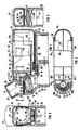
- FIG 1 ein Taschen-Inhalationsgerät mit eingesetzter Dosierkartusche im Längsschnitt;
- FIG 2 das Gerät von Figur 1 im Querschnitt entlang der Linie II-II;
- FIG 3 das Gerät von Figur 1 im Querschnitt entlang der Linie III-III; und
- FIG 4 das Gerät von Figur 1 im Schnitt entlang der Linie IV-IV, wobei die Dosierkartusche und die Lasche nicht gezeigt und die Fenster herausgenommen sind.
- 1 shows a pocket inhalation device with inserted dosing cartridge in longitudinal section;
- 2 shows the device of Figure 1 in cross section along the line II-II;
- 3 shows the device of Figure 1 in cross section along the line III-III; and
- 4 shows the device of Figure 1 in section along the line IV-IV, wherein the dosing cartridge and the tab are not shown and the windows are removed.
Das dargestellte Taschen-Inhalationsgerät umfaßt ein Gehäuse 2 aus Kunststoff mit einem Unterteil 2a und einem darauf lösbar befestigten Oberteil 2b. Die lösbare Befestigung ist durch zumindest eine federnde Seitenwand 4 und einen Schnapp- oder Rastverschluß 6 sichergestellt.The pocket inhalation device shown comprises a
Im Unterteil 2a ist ein piezoelektrisches Schwingsystem oder Ultraschall-Zerstäuber 8 mit nach oben weisendem Zerstäuberteller 10 untergebracht. Dieser Zerstäuber 8 arbeitet mit einer Betriebsfrequenz im Bereich von 1 bis 5 MHz. Die elektrische Energie hierfür wird von einer Elektronikschaltung 12 bereitgestellt, die sich in einer abgeschlossenen vorderen Kammer befindet. In dieser Kammer ist auch ein magnetisch betätigbarer Schalter 14, insbesondere ein Reed-Kontakt, untergebracht. Er befindet sich an der oberen Wand 16 des Unterteils 2a, die auch als Zwischenwand bezeichnet werden kann. In einer hinteren Kammer ist ein Akkumulator 18 austauschbar eingesetzt. Er versorgt die Elektronikschaltung 12 mit elektrischer Energie. Die vordere und die hintere Kammer sind flüssigkeitsdicht abgeschlossen. Zu diesem Zweck ist der Ultraschall-Zerstäuber 8 in der vorderen Kammer bevorzugt zum Beispiel mit einer Vergußmasse 20 eingegossen.In the
Im Bereich des Ultraschall-Zerstäubers 8, und zwar in seiner unmittelbaren Nähe, ist eine mit kleinen runden Löchern versehene Siebplatte oder Abschlußwand 22 vorgesehen. Stattdessen könnte sie auch mit Schlitzen oder rechteckigen Durchbrüchen versehen sein. Die Wand 22 ist etwa halbringförmig geformt. Sie besitzt im zentralen Teil eine größere Öffnung 24, in die der Zerstäuberteller 10 mit seiner Zerstäuberfläche hineinragt. Zwischen dem Zerstäuberteller 10 und dem Rand der Öffnung 24 ergibt sich somit ein etwa ringförmiger Trennspalt. Die Abschluß wand 22 hat zwei Funktionen: Zum einen dient sie zum mechanischen Schutz des Zerstäubers 8 und des Zerstäubertellers 10 vor Beschädigungen, und zum anderen wird infolge der Vielzahl kleiner Öffnungen im darüberliegenden Raum 26, der als Aerosol-Raum bezeichnet werden kann, eine laminare Strömung erreicht. Diese tritt auf, sobald Luft über eine Lufteinlaßöffnung 28, die mit dem Aerosol-Raum 26 in Verbindung steht und die bevorzugt als Schlitz mit Schlitzrändern 28a und 28b (vergl. Fig. 4) ausgebildet ist, angesogen wird. Die Wand 22 kann somit als Mittel zur Laminarisierung der angesaugten Luft angesehen werden. Auch andere solche Mittel können vorliegend eingesetzt werden. Die Lufteinlaßöffnung 28 ist vorliegend unmittelbar unterhalb der Wand 22 im Gehäuse 2 angeordnet.In the area of the
Die Oberfläche des Zerstäubertellers 10 steht leicht schräg zur Wand 22, die auch als Lochgitter bezeichnet werden kann. Diese Schrägstellung des Ultraschall-Zerstäubers 8 mit Richtung auf den Mund des Benutzers trägt zu einem kompakten Aufbau des Inhalationsgeräts bei. Zugleich sorgt sie für eine Zerstäubung in Richtung der Austrittsöffnung des Aerosol-Raums 26. Durch die Lochung der Wand 22 ist eine ausreichende Reinigung des Schwingerbereiches möglich.The surface of the
Der Aerosol-Raum 26 ist im vorderen Teil des Oberteils 2b angeordnet. Er läuft in ein im wesentlichen ovales Mundstück 30 aus, dessen Ausgangsöffnung mit einem Kunststoff-Deckel 32 verschließbar ist. Dabei kann die Ebene der Wand 22 im Winkel von etwa 45° zur Achse 31 des Mundstücks 30 ausgerichtet sein.The aerosol space 26 is arranged in the front part of the
Der Aerosol-Raum 26 ist über eine Führungsöffnung 34 mit einem hinteren Raum 36 verbunden, in dem eine generell mit 40 bezeichnete Einrichtung zur Zuführung eines Medikaments zum Ultraschall-Zerstäuber 10 untergebracht ist. Diese Einrichtung 40 umfaßt eine an sich bekannte, in sich verschiebbare Dosierkartusche 42 mit einem zylindrischen Vorderteil 42a und einem darin verschiebbaren zylindrischen Rückteil 42b, das das Medi kament enthält. Am Vorderteil 42a ist ein Dosierröhrchen 44 mit hinteren Absätzen als Kartuschenspitze angebracht. Dessen Dosieröffnung ist mit 46 bezeichnet. Das Dosierröhrchen 44 liegt bei liegend eingeschobener Dosierkartusche 42 unter Freilassung eines Ringspalts in der Führungsöffnung 34. Diese Führungsöffnung 34 dient also der exakten Positionierung. Wichtig ist dabei, daß die Spitze der Dosierkartusche 42 mit einem der genannten Absätze an einem Anschlag 48 anliegt, der z. B. durch die Wand der Dosieröffnung 46 gebildet wird. Dieser Anschlag 48 ist wichtig für die Zentrierung, aber auch für das Festhalten der Dosierkartusche 42 beim Dosieren. Die Zentrierung und Führung wird im übrigen auch durch Längsrippen 50, 52 im Raum 36 sichergestellt.The aerosol space 26 is connected via a guide opening 34 to a
Die Einrichtung 40 zur Zuführung des Medikaments umfaßt weiter einen endseitig auf die Dosierkartusche 42 aufgesetzten Drücker 54. Der Drücker 54 ist dabei auf das Ende der Dosierkartusche 42 fest aufgeschoben; er ist aber - beim Austauschen der Dosierkartusche 42 - auch ohne weiteres von diesem Ende wieder abziehbar. Die Dimensionierung ist so getroffen, daß der Drücker 54 in der ungedrückten Normalstellung mit seiner Rückfläche etwa das Gehäuse 2 hinten abschließt; bei Betätigung wird er weiter in das Oberteil 2b eingeschoben. Der Drücker 54 selbst dient damit zur exakten Halterung der Kartusche 42.The
Aus einem Vergleich von Figur 1 und Figur 4 ergibt sich, daß der Drücker 54 als halbzylindrischer Hohlkörper ausgebildet ist. Seine untere Stirnwand oder untere Seite läuft in eine Lasche 56 aus. Mit anderen Worten, die Lasche 56 ist an den Drücker 54 angearbeitet. Diese Lasche 56 ist dabei im wesentlichen ein rechteckförmiges Kunststoffteil. Sie ist an ihrer Oberseite bevorzugt mit einer Längsrippe 58 versehen, um die Stabilität zu erhöhen. Wie später deutlich werden wird, dient die Oberkante dieser Längsrippe 58 ebenso wie die Unterseite der Lasche 56 als Gleitfläche, und zwar sowohl beim Einsetzen der Kartusche 42 als auch beim Dosieren.A comparison of FIG. 1 and FIG. 4 shows that the
Am vorderen Ende der Lasche 56 ist ein Magnet 60 befestigt. Bei aufgeschobenem Drücker 54 liegen die Lasche 56, die Längsrippe 58 und der Magnet 60 in einem Raum 62 zwischen dem Unterteil 2a und dem Oberteil 2b. In diesem Raum 62 ist die Lasche 56 bei Betätigung des Drückers 54 längsverschiebbar. Verschmutzungen sind nicht zu befürchten. Beim Verschieben wird der Magnet 60 relativ zum Schalter 14 nach links verschoben. Gelangt er in dessen magnetischen Einflußbereich, so wird der Schalter 14 betätigt. Hierdurch wird - nach Loslassen des Drückers 54 und beim Öffnen des Schalters 14 - mit Hilfe der Elektronikschaltung 12 eine Ultraschall-Erregung des Zerstäubers 8 ausgelöst. Die Lasche 56, die Längsrippe 58 und der Drücker 54 können als gemeinsames Spritzgußteil ausgebildet sein. Aus Figur 1 wird deutlich, daß der Magnet 60, der z. B. zylinderförmig geformt sein kann, in die Lasche 56 und die Längsrippe 58 eingelassen ist, und daß er im wesentlichen bündig mit der dem Schalter 14 zugewandten Fläche der Lasche 56 abschließt. Bei Betätigung wird der Magnet 60 entlang der Wand 16 des Gehäuses 2 verschoben. Bei Entlastung durch den Finger des Benutzers fährt die Kartusche 42 infolge ihrer Federkraft (und damit auch der Magnet 60) wieder in ihre dargestellte Ausgangsstellung zurück.A
Die Führung der Lasche 56 im Raum 62 erfolgt mit Hilfe von zwei Seitenwänden 64, 66, die in einigem Abstand parallel zueinander an der Unterseite des Oberteils 2b befestigt sind.The
An den beiden parallelen Seitenlängswänden 2b1, 2b2 des Oberteils 2b sind einander gegenüberliegend zwei Fenster 68, 70 angeordnet, über die eine Beobachtung des Füllstands der durchsichtigen, aus Kunststoff bestehenden Kartusche 42 möglich ist. Die Dosierkartusche 42 liegt dabei im eingeschobenen Zustand zwischen diesen beiden Fenstern 68, 70. Die Fenster 68, 70 sind bevorzugt aus Kunststoff ausgeführt und mit Rastnasen 69, 71 ausgestattet, so daß sie in entsprechende Öffnungen in den Seitenlängswänden des Oberteils 2b eingeklipst werden können. Diese Rastnasen 69, 71 sind so geformt, daß sie eine Sicherung gegen ein unbeabsichtigtes Herausziehen oder Herausfallen der Dosierkartusche 42 bilden.On the two parallel side longitudinal walls 2b1, 2b2 of the
Im Bereich des Zerstäubertellers 10 ist an der dort vorhandenen Führungsöffnung 34 eine Senke oder Eindellung 74 im Material vorgesehen. Dadurch wird die Kapillarwirkung im Ringspalt der Führungsöffnung 34 für das austretende Medikamententröpfchen beim Dosieren herabgesetzt. Mit anderen Worten: Der Abstand zwischen der Austrittsöffnung 46 und der Oberfläche des Zerstäubertellers 10 ist für das austretende Dosiertröpfchen kleiner als zwischen der Dosieröffnung 46 und dem Boden der Senke 74. Hierdurch wird die Körperanhangskraft des Zerstäubertellers 10 bezüglich des Tröpfchens unterstützt, so daß beim Dosieren gewährleistet ist, daß dieses auf der Oberfläche des Zerstäubertellers 10 plaziert wird und nicht etwa im Bereich des Ringspalts an der Öffnung 24. Ein eventuelles Rückfließen des Medikamententröpfchens über eine mögliche Kapillare zwischen dem Außendurchmesser der Kartuschenspitze und der Führungsöffnung des Oberteils 2b wird also durch einen entsprechend vergrößerten Führungsöffnungsdurchmesser erreicht.In the area of the
Das Unter- und Oberteil 2a bzw. 2b kann jeweils aus zwei Hälften oder Schalen zusammengesetzt sein. Dies ist in Figur 4 für das Unterteil 2a durch die Ansatzlinie 76 veranschaulicht.The lower and
Wie bereits früher dargelegt, ist das Oberteil 2b von oben auf das Unterteil 2a aufsetzbar und dort mit Hilfe des Rastverschlusses 6 einrast- oder einklemmbar. Drückt der Benutzer nun auf den Drücker 54, so wird das Rückteil 42b in das Vorderteil 42a der Dosierkartusche 42 eingedrückt und ein Medikamententröpfchen an den Zerstäuberteller 10 abgegeben. Gleichzeitig bewegt sich der an der Lasche 56 befestigte Magnet 60 mit dieser in Richtung auf den Schalter 14 und schließt denselben. Nach Loslassen des Drückers 54 und Öffnen des Schalters 14 wird aufgrund des Schaltvorgangs das Tröpfchen auf dem Zerstäuberteller 10 durch Ultraschallschwingungen zerstäubt. Es wird in ein Aerosol umgewandelt, das in den Raum 22 übergeht. Dieses kann vom Benutzer über das Mundstück 30 (bei abgenommenem Deckel 32) eingeatmet werden. Beim Einatmen wird Luft über die Lufteinlaßöffnung 28 eingesogen. Infolge der durch die Siebplatte 22 bewirkten laminaren Störung findet nur ein geringer Niederschlag des Medikaments an den Innenflächen des Raums 26 statt. Dies ist ein erheblicher Vorteil für die Betriebssicherheit und die Hygiene.As already explained earlier, the
Es soll noch betont werden, daß das Laminarisierungsmittel prinzipiell auch im Oberteil 2b angeordnet sein kann, z. B. ebenfalls in Form eines Gitters.It should be emphasized that the laminarizing agent can in principle also be arranged in the
Claims (12)
gekennzeichnet durch eine im Gehäuse (2) angebrachte Lufteinlaß-Öffnung (28), die mit dem Raum (26) vor dem Ultraschall-Zerstäuber (8) in Verbindung steht.
characterized by an air inlet opening (28) made in the housing (2) and communicating with the space (26) in front of the ultrasonic atomizer (8).
Priority Applications (5)
| Application Number | Priority Date | Filing Date | Title |
|---|---|---|---|
| EP88120823A EP0373237A1 (en) | 1988-12-13 | 1988-12-13 | Pocket inhaler device |
| DK617989A DK617989A (en) | 1988-12-13 | 1989-12-07 | INHALER, ISAER POCKET INHALER |
| US07/449,705 US5134993A (en) | 1988-12-13 | 1989-12-11 | Inhalator device, in particular a pocket inhalator |
| CA002005151A CA2005151A1 (en) | 1988-12-13 | 1989-12-11 | Inhalator device, in particular a pocket inhalator |
| JP1322441A JPH02243166A (en) | 1988-12-13 | 1989-12-12 | Inhailer |
Applications Claiming Priority (1)
| Application Number | Priority Date | Filing Date | Title |
|---|---|---|---|
| EP88120823A EP0373237A1 (en) | 1988-12-13 | 1988-12-13 | Pocket inhaler device |
Publications (1)
| Publication Number | Publication Date |
|---|---|
| EP0373237A1 true EP0373237A1 (en) | 1990-06-20 |
Family
ID=8199653
Family Applications (1)
| Application Number | Title | Priority Date | Filing Date |
|---|---|---|---|
| EP88120823A Withdrawn EP0373237A1 (en) | 1988-12-13 | 1988-12-13 | Pocket inhaler device |
Country Status (5)
| Country | Link |
|---|---|
| US (1) | US5134993A (en) |
| EP (1) | EP0373237A1 (en) |
| JP (1) | JPH02243166A (en) |
| CA (1) | CA2005151A1 (en) |
| DK (1) | DK617989A (en) |
Cited By (7)
| Publication number | Priority date | Publication date | Assignee | Title |
|---|---|---|---|---|
| WO1992021332A1 (en) * | 1991-05-25 | 1992-12-10 | Boehringer Ingelheim Kg | Process for producing therapeutically usable aerosols |
| FR2705911A1 (en) * | 1993-06-02 | 1994-12-09 | Oreal | Piezoelectric nebulization device. |
| EP0635312A1 (en) * | 1992-04-09 | 1995-01-25 | Omron Corporation | Ultrasonic atomizer, ultrasonic inhalator and method of controlling same |
| EP0642802A2 (en) * | 1993-08-09 | 1995-03-15 | Disetronic Ag | Inhalation device |
| US5950619A (en) * | 1995-03-14 | 1999-09-14 | Siemens Aktiengesellschaft | Ultrasonic atomizer device with removable precision dosating unit |
| US5970974A (en) * | 1995-03-14 | 1999-10-26 | Siemens Aktiengesellschaft | Dosating unit for an ultrasonic atomizer device |
| DE102004006450A1 (en) * | 2004-02-05 | 2005-08-25 | Ing. Erich Pfeiffer Gmbh | metering |
Families Citing this family (85)
| Publication number | Priority date | Publication date | Assignee | Title |
|---|---|---|---|---|
| IE62780B1 (en) * | 1988-09-10 | 1995-02-22 | Fisons Plc | Inhalation devices with a reduced risk of blockage |
| DE69127826T2 (en) * | 1990-12-17 | 1998-04-09 | Minnesota Mining & Mfg | INHALATION DEVICE |
| AU651882B2 (en) * | 1991-05-14 | 1994-08-04 | Visiomed Group Limited | Aerosol inhalation device |
| US5452711A (en) * | 1992-12-24 | 1995-09-26 | Exar Corporation | Small form factor atomizer |
| US5709202A (en) * | 1993-05-21 | 1998-01-20 | Aradigm Corporation | Intrapulmonary delivery of aerosolized formulations |
| US5497763A (en) * | 1993-05-21 | 1996-03-12 | Aradigm Corporation | Disposable package for intrapulmonary delivery of aerosolized formulations |
| GB9324250D0 (en) * | 1993-11-25 | 1994-01-12 | Minnesota Mining & Mfg | Inhaler |
| US5505194A (en) * | 1994-03-23 | 1996-04-09 | Abbott Laboratories | Aerosol inhalation device having slideably and rotatably connected elliptical cylinder portions |
| US5435282A (en) * | 1994-05-19 | 1995-07-25 | Habley Medical Technology Corporation | Nebulizer |
| US5758637A (en) | 1995-08-31 | 1998-06-02 | Aerogen, Inc. | Liquid dispensing apparatus and methods |
| WO1997002856A1 (en) * | 1995-07-10 | 1997-01-30 | A & D Company, Limited | Handy atomizer |
| US6234167B1 (en) * | 1998-10-14 | 2001-05-22 | Chrysalis Technologies, Incorporated | Aerosol generator and methods of making and using an aerosol generator |
| US6196218B1 (en) * | 1999-02-24 | 2001-03-06 | Ponwell Enterprises Ltd | Piezo inhaler |
| US6235177B1 (en) | 1999-09-09 | 2001-05-22 | Aerogen, Inc. | Method for the construction of an aperture plate for dispensing liquid droplets |
| US6962151B1 (en) * | 1999-11-05 | 2005-11-08 | Pari GmbH Spezialisten für effektive Inhalation | Inhalation nebulizer |
| ES2305057T3 (en) | 2000-02-28 | 2008-11-01 | Pharmakodex Limited | DEVICE FOR THE ADMINISTRATION OF ORAL PHARMACES. |
| MY136453A (en) | 2000-04-27 | 2008-10-31 | Philip Morris Usa Inc | "improved method and apparatus for generating an aerosol" |
| US6883516B2 (en) | 2000-04-27 | 2005-04-26 | Chrysalis Technologies Incorporated | Method for generating an aerosol with a predetermined and/or substantially monodispersed particle size distribution |
| US6748944B1 (en) * | 2000-05-03 | 2004-06-15 | Dellavecchia Michael Anthony | Ultrasonic dosage device and method |
| MXPA02010884A (en) * | 2000-05-05 | 2003-03-27 | Aerogen Ireland Ltd | Apparatus and methods for the delivery of medicaments to the respiratory system. |
| US8336545B2 (en) | 2000-05-05 | 2012-12-25 | Novartis Pharma Ag | Methods and systems for operating an aerosol generator |
| US7971588B2 (en) | 2000-05-05 | 2011-07-05 | Novartis Ag | Methods and systems for operating an aerosol generator |
| US6543443B1 (en) * | 2000-07-12 | 2003-04-08 | Aerogen, Inc. | Methods and devices for nebulizing fluids |
| US6629524B1 (en) | 2000-07-12 | 2003-10-07 | Ponwell Enterprises Limited | Inhaler |
| WO2002016235A1 (en) * | 2000-08-18 | 2002-02-28 | Norton Healthcare Limited | Spray device |
| US6435175B1 (en) * | 2000-08-29 | 2002-08-20 | Sensormedics Corporation | Pulmonary drug delivery device |
| US6964647B1 (en) | 2000-10-06 | 2005-11-15 | Ellaz Babaev | Nozzle for ultrasound wound treatment |
| US6601581B1 (en) * | 2000-11-01 | 2003-08-05 | Advanced Medical Applications, Inc. | Method and device for ultrasound drug delivery |
| US6491233B2 (en) | 2000-12-22 | 2002-12-10 | Chrysalis Technologies Incorporated | Vapor driven aerosol generator and method of use thereof |
| US6681998B2 (en) | 2000-12-22 | 2004-01-27 | Chrysalis Technologies Incorporated | Aerosol generator having inductive heater and method of use thereof |
| US6701921B2 (en) | 2000-12-22 | 2004-03-09 | Chrysalis Technologies Incorporated | Aerosol generator having heater in multilayered composite and method of use thereof |
| US6761729B2 (en) | 2000-12-22 | 2004-07-13 | Advanced Medicalapplications, Inc. | Wound treatment method and device with combination of ultrasound and laser energy |
| US6799572B2 (en) | 2000-12-22 | 2004-10-05 | Chrysalis Technologies Incorporated | Disposable aerosol generator system and methods for administering the aerosol |
| US6501052B2 (en) | 2000-12-22 | 2002-12-31 | Chrysalis Technologies Incorporated | Aerosol generator having multiple heating zones and methods of use thereof |
| US6533803B2 (en) | 2000-12-22 | 2003-03-18 | Advanced Medical Applications, Inc. | Wound treatment method and device with combination of ultrasound and laser energy |
| US7077130B2 (en) | 2000-12-22 | 2006-07-18 | Chrysalis Technologies Incorporated | Disposable inhaler system |
| US7914470B2 (en) | 2001-01-12 | 2011-03-29 | Celleration, Inc. | Ultrasonic method and device for wound treatment |
| US6569099B1 (en) | 2001-01-12 | 2003-05-27 | Eilaz Babaev | Ultrasonic method and device for wound treatment |
| US8235919B2 (en) | 2001-01-12 | 2012-08-07 | Celleration, Inc. | Ultrasonic method and device for wound treatment |
| US6960173B2 (en) * | 2001-01-30 | 2005-11-01 | Eilaz Babaev | Ultrasound wound treatment method and device using standing waves |
| US6550472B2 (en) * | 2001-03-16 | 2003-04-22 | Aerogen, Inc. | Devices and methods for nebulizing fluids using flow directors |
| US6623444B2 (en) | 2001-03-21 | 2003-09-23 | Advanced Medical Applications, Inc. | Ultrasonic catheter drug delivery method and device |
| US6478754B1 (en) | 2001-04-23 | 2002-11-12 | Advanced Medical Applications, Inc. | Ultrasonic method and device for wound treatment |
| US6640050B2 (en) | 2001-09-21 | 2003-10-28 | Chrysalis Technologies Incorporated | Fluid vaporizing device having controlled temperature profile heater/capillary tube |
| US6568390B2 (en) | 2001-09-21 | 2003-05-27 | Chrysalis Technologies Incorporated | Dual capillary fluid vaporizing device |
| US6681769B2 (en) | 2001-12-06 | 2004-01-27 | Crysalis Technologies Incorporated | Aerosol generator having a multiple path heater arrangement and method of use thereof |
| US6804458B2 (en) | 2001-12-06 | 2004-10-12 | Chrysalis Technologies Incorporated | Aerosol generator having heater arranged to vaporize fluid in fluid passage between bonded layers of laminate |
| US6701922B2 (en) | 2001-12-20 | 2004-03-09 | Chrysalis Technologies Incorporated | Mouthpiece entrainment airflow control for aerosol generators |
| MXPA04006629A (en) | 2002-01-07 | 2004-11-10 | Aerogen Inc | Devices and methods for nebulizing fluids for inhalation. |
| US7677467B2 (en) | 2002-01-07 | 2010-03-16 | Novartis Pharma Ag | Methods and devices for aerosolizing medicament |
| ES2603067T3 (en) | 2002-01-15 | 2017-02-23 | Novartis Ag | Methods and systems for operating an aerosol generator |
| ES2572770T3 (en) | 2002-05-20 | 2016-06-02 | Novartis Ag | Apparatus for providing spray for medical treatment and methods |
| US20040039755A1 (en) * | 2002-06-05 | 2004-02-26 | Matthew Kunze | Metadata relationships |
| JP4243499B2 (en) * | 2002-06-11 | 2009-03-25 | 富士通株式会社 | Bonded substrate manufacturing apparatus and bonded substrate manufacturing method |
| US8545463B2 (en) | 2003-05-20 | 2013-10-01 | Optimyst Systems Inc. | Ophthalmic fluid reservoir assembly for use with an ophthalmic fluid delivery device |
| US7883031B2 (en) | 2003-05-20 | 2011-02-08 | James F. Collins, Jr. | Ophthalmic drug delivery system |
| US8616195B2 (en) | 2003-07-18 | 2013-12-31 | Novartis Ag | Nebuliser for the production of aerosolized medication |
| US7367334B2 (en) | 2003-08-27 | 2008-05-06 | Philip Morris Usa Inc. | Fluid vaporizing device having controlled temperature profile heater/capillary tube |
| US7946291B2 (en) | 2004-04-20 | 2011-05-24 | Novartis Ag | Ventilation systems and methods employing aerosol generators |
| BRPI0611198B1 (en) | 2005-05-25 | 2018-02-06 | Aerogen, Inc. | VIBRATION SYSTEMS AND METHODS |
| US7713218B2 (en) | 2005-06-23 | 2010-05-11 | Celleration, Inc. | Removable applicator nozzle for ultrasound wound therapy device |
| US7785277B2 (en) | 2005-06-23 | 2010-08-31 | Celleration, Inc. | Removable applicator nozzle for ultrasound wound therapy device |
| US20070012316A1 (en) * | 2005-07-14 | 2007-01-18 | Joann Truza | Disposable compact rescue inhaler |
| US9101949B2 (en) | 2005-08-04 | 2015-08-11 | Eilaz Babaev | Ultrasonic atomization and/or seperation system |
| US7896539B2 (en) | 2005-08-16 | 2011-03-01 | Bacoustics, Llc | Ultrasound apparatus and methods for mixing liquids and coating stents |
| US20080183200A1 (en) * | 2006-06-07 | 2008-07-31 | Bacoustics Llc | Method of selective and contained ultrasound debridement |
| US7431704B2 (en) | 2006-06-07 | 2008-10-07 | Bacoustics, Llc | Apparatus and method for the treatment of tissue with ultrasound energy by direct contact |
| US8562547B2 (en) * | 2006-06-07 | 2013-10-22 | Eliaz Babaev | Method for debriding wounds |
| US8156933B2 (en) | 2006-06-21 | 2012-04-17 | Puthalath Koroth Raghuprasad | Cloud nebulizer |
| AU2007286660A1 (en) * | 2006-08-25 | 2008-02-28 | Eilaz Babaev | Portable ultrasound device for the treatment of wounds |
| FR2908329B1 (en) | 2006-11-14 | 2011-01-07 | Telemaq | DEVICE AND METHOD FOR ULTRASOUND FLUID DELIVERY |
| US8491521B2 (en) | 2007-01-04 | 2013-07-23 | Celleration, Inc. | Removable multi-channel applicator nozzle |
| US7753285B2 (en) | 2007-07-13 | 2010-07-13 | Bacoustics, Llc | Echoing ultrasound atomization and/or mixing system |
| US7780095B2 (en) | 2007-07-13 | 2010-08-24 | Bacoustics, Llc | Ultrasound pumping apparatus |
| WO2012009706A1 (en) | 2010-07-15 | 2012-01-19 | Corinthian Ophthalmic, Inc. | Drop generating device |
| EP2485691B1 (en) | 2010-07-15 | 2020-03-18 | Eyenovia, Inc. | Ophthalmic drug delivery |
| CA2805635A1 (en) | 2010-07-15 | 2012-01-19 | Corinthian Ophthalmic, Inc. | Method and system for performing remote treatment and monitoring |
| US10154923B2 (en) | 2010-07-15 | 2018-12-18 | Eyenovia, Inc. | Drop generating device |
| JP6105621B2 (en) | 2011-12-12 | 2017-03-29 | アイノビア,インコーポレイティド | Highly elastic polymer ejector mechanism, ejector apparatus and method of using them |
| US11224767B2 (en) | 2013-11-26 | 2022-01-18 | Sanuwave Health, Inc. | Systems and methods for producing and delivering ultrasonic therapies for wound treatment and healing |
| US11273271B2 (en) | 2014-07-01 | 2022-03-15 | Aerami Therapeutics, Inc. | Aerosolization system with flow restrictor and feedback device |
| US10471222B2 (en) | 2014-07-01 | 2019-11-12 | Dance Biopharm Inc. | Aerosolization system with flow restrictor and feedback device |
| WO2016159889A1 (en) | 2015-04-02 | 2016-10-06 | Hill-Rom Services Pte. Ltd. | Manifold for respiratory device |
| EA037426B1 (en) * | 2017-02-08 | 2021-03-26 | Джапан Тобакко Инк. | Cartridge and inhaler |
| CN115300226A (en) | 2017-06-10 | 2022-11-08 | 艾诺维亚股份有限公司 | Apparatus for delivering a volume of fluid to an eye |
Citations (7)
| Publication number | Priority date | Publication date | Assignee | Title |
|---|---|---|---|---|
| BE531640A (en) * | ||||
| DE1103522B (en) * | 1957-10-24 | 1961-03-30 | Transform Roentgen Matern Veb | Exhalation device for aerosols generated by means of ultrasound |
| DE2524862A1 (en) * | 1974-06-06 | 1975-12-11 | Tdk Electronics Co Ltd | Vibration generator for a liquid atomizer |
| FR2285930A1 (en) * | 1974-09-25 | 1976-04-23 | Siemens Ag | ULTRASONIC LIQUID PULVERIZER |
| US4109863A (en) * | 1977-08-17 | 1978-08-29 | The United States Of America As Represented By The United States Department Of Energy | Apparatus for ultrasonic nebulization |
| FR2444504A1 (en) * | 1978-12-19 | 1980-07-18 | Bosch Siemens Hausgeraete | LIQUID ATOMIZER, PARTICULARLY INHALATION APPARATUS |
| EP0258637A1 (en) * | 1986-08-11 | 1988-03-09 | Siemens Aktiengesellschaft | Ultrasonic pocket sprayer |
Family Cites Families (4)
| Publication number | Priority date | Publication date | Assignee | Title |
|---|---|---|---|---|
| US4094317A (en) * | 1976-06-11 | 1978-06-13 | Wasnich Richard D | Nebulization system |
| US4113809A (en) * | 1977-04-04 | 1978-09-12 | Champion Spark Plug Company | Hand held ultrasonic nebulizer |
| DE3339180C2 (en) * | 1983-10-28 | 1993-10-14 | Pfeiffer Erich Gmbh & Co Kg | Discharge device for media |
| US4976259A (en) * | 1986-12-22 | 1990-12-11 | Mountain Medical Equipment, Inc. | Ultrasonic nebulizer |
-
1988
- 1988-12-13 EP EP88120823A patent/EP0373237A1/en not_active Withdrawn
-
1989
- 1989-12-07 DK DK617989A patent/DK617989A/en unknown
- 1989-12-11 US US07/449,705 patent/US5134993A/en not_active Expired - Fee Related
- 1989-12-11 CA CA002005151A patent/CA2005151A1/en not_active Abandoned
- 1989-12-12 JP JP1322441A patent/JPH02243166A/en active Pending
Patent Citations (7)
| Publication number | Priority date | Publication date | Assignee | Title |
|---|---|---|---|---|
| BE531640A (en) * | ||||
| DE1103522B (en) * | 1957-10-24 | 1961-03-30 | Transform Roentgen Matern Veb | Exhalation device for aerosols generated by means of ultrasound |
| DE2524862A1 (en) * | 1974-06-06 | 1975-12-11 | Tdk Electronics Co Ltd | Vibration generator for a liquid atomizer |
| FR2285930A1 (en) * | 1974-09-25 | 1976-04-23 | Siemens Ag | ULTRASONIC LIQUID PULVERIZER |
| US4109863A (en) * | 1977-08-17 | 1978-08-29 | The United States Of America As Represented By The United States Department Of Energy | Apparatus for ultrasonic nebulization |
| FR2444504A1 (en) * | 1978-12-19 | 1980-07-18 | Bosch Siemens Hausgeraete | LIQUID ATOMIZER, PARTICULARLY INHALATION APPARATUS |
| EP0258637A1 (en) * | 1986-08-11 | 1988-03-09 | Siemens Aktiengesellschaft | Ultrasonic pocket sprayer |
Cited By (15)
| Publication number | Priority date | Publication date | Assignee | Title |
|---|---|---|---|---|
| WO1992021332A1 (en) * | 1991-05-25 | 1992-12-10 | Boehringer Ingelheim Kg | Process for producing therapeutically usable aerosols |
| US6651650B1 (en) | 1992-04-09 | 2003-11-25 | Omron Corporation | Ultrasonic atomizer, ultrasonic inhaler and method of controlling same |
| EP0635312A1 (en) * | 1992-04-09 | 1995-01-25 | Omron Corporation | Ultrasonic atomizer, ultrasonic inhalator and method of controlling same |
| US6901926B2 (en) | 1992-04-09 | 2005-06-07 | Omron Corporation | Ultrasonic atomizer, ultrasonic inhaler and method of controlling same |
| EP0635312A4 (en) * | 1992-04-09 | 1996-01-10 | Omron Tateisi Electronics Co | Ultrasonic atomizer, ultrasonic inhalator and method of controlling same. |
| FR2705911A1 (en) * | 1993-06-02 | 1994-12-09 | Oreal | Piezoelectric nebulization device. |
| EP0628356A1 (en) * | 1993-06-02 | 1994-12-14 | L'oreal | Piezoelectrical nebuliser |
| US5529055A (en) * | 1993-06-02 | 1996-06-25 | L'oreal | Piezoelectric nebulizing apparatus |
| EP0642802A3 (en) * | 1993-08-09 | 1996-03-13 | Disetronic Ag | Inhalation device. |
| EP0642802A2 (en) * | 1993-08-09 | 1995-03-15 | Disetronic Ag | Inhalation device |
| US5970974A (en) * | 1995-03-14 | 1999-10-26 | Siemens Aktiengesellschaft | Dosating unit for an ultrasonic atomizer device |
| US5950619A (en) * | 1995-03-14 | 1999-09-14 | Siemens Aktiengesellschaft | Ultrasonic atomizer device with removable precision dosating unit |
| DE102004006450A1 (en) * | 2004-02-05 | 2005-08-25 | Ing. Erich Pfeiffer Gmbh | metering |
| US7779830B2 (en) | 2004-02-05 | 2010-08-24 | Ing. Erich Pfeiffer Gmbh | Dosing device |
| DE102004006450B4 (en) * | 2004-02-05 | 2012-09-27 | Ing. Erich Pfeiffer Gmbh | metering |
Also Published As
| Publication number | Publication date |
|---|---|
| DK617989A (en) | 1990-06-14 |
| US5134993A (en) | 1992-08-04 |
| JPH02243166A (en) | 1990-09-27 |
| DK617989D0 (en) | 1989-12-07 |
| CA2005151A1 (en) | 1990-06-13 |
Similar Documents
| Publication | Publication Date | Title |
|---|---|---|
| EP0373237A1 (en) | Pocket inhaler device | |
| EP0258637B1 (en) | Ultrasonic pocket sprayer | |
| DE3046108C2 (en) | ||
| DE112009000533B4 (en) | Inhaler and inhalation aid used for it | |
| DE60027714T3 (en) | DRAINAGE SYSTEM WITH LOW SPRAY POWER AND RETENTION | |
| EP0167581B1 (en) | Inhalation device | |
| EP0540774B1 (en) | Fluid atomizing device | |
| EP0147755B1 (en) | Inhalator | |
| DE60212764T2 (en) | inhaler | |
| DE60033167T2 (en) | INTERNAL COMBINATION DEVICE FOR A INHALER | |
| EP1509266B1 (en) | System comprising a nozzle and a fixing system | |
| EP1720591B1 (en) | Atomiser | |
| DE2716323C2 (en) | Device for inhalation of medicaments | |
| WO2001024857A1 (en) | Breathing-controlled inhalation device for dry powder and method for the even distribution of said dry powder in the air | |
| DE1287260B (en) | Spray device | |
| DE69632192T2 (en) | ELECTROSTATIC SPRAYING | |
| EP1342483A2 (en) | Capsule holder | |
| DE2849493A1 (en) | AEROSOL DISPENSER TO BE HOLDED IN HAND | |
| DE19708406A1 (en) | Device for dispensing substances | |
| EP0549605A1 (en) | Inhalator without propeller gas with foreign air stream. | |
| EP0667793A1 (en) | Method and device for producing an aerosol from a substance in powder form. | |
| EP2712643A1 (en) | Inhalator | |
| DE202017101591U1 (en) | Apparatus for oral or intranasal administration of a pharmaceutically active medication | |
| DE102006032293A1 (en) | Device for the metered delivery of sprayable substances | |
| DE4322111C2 (en) | Inhalation nebulizer |
Legal Events
| Date | Code | Title | Description |
|---|---|---|---|
| PUAI | Public reference made under article 153(3) epc to a published international application that has entered the european phase |
Free format text: ORIGINAL CODE: 0009012 |
|
| AK | Designated contracting states |
Kind code of ref document: A1 Designated state(s): AT BE CH DE ES FR GB GR IT LI NL SE |
|
| RBV | Designated contracting states (corrected) |
Designated state(s): AT BE CH DE ES FR GB IT LI NL SE |
|
| 17P | Request for examination filed |
Effective date: 19901219 |
|
| 17Q | First examination report despatched |
Effective date: 19920331 |
|
| STAA | Information on the status of an ep patent application or granted ep patent |
Free format text: STATUS: THE APPLICATION IS DEEMED TO BE WITHDRAWN |
|
| 18D | Application deemed to be withdrawn |
Effective date: 19930217 |