JP4348922B2 - Liquid ejection apparatus and liquid ejection method - Google Patents
Liquid ejection apparatus and liquid ejection method Download PDFInfo
- Publication number
- JP4348922B2 JP4348922B2 JP2002286930A JP2002286930A JP4348922B2 JP 4348922 B2 JP4348922 B2 JP 4348922B2 JP 2002286930 A JP2002286930 A JP 2002286930A JP 2002286930 A JP2002286930 A JP 2002286930A JP 4348922 B2 JP4348922 B2 JP 4348922B2
- Authority
- JP
- Japan
- Prior art keywords
- nozzles
- medium
- liquid
- nozzle
- light
- Prior art date
- Legal status (The legal status is an assumption and is not a legal conclusion. Google has not performed a legal analysis and makes no representation as to the accuracy of the status listed.)
- Expired - Fee Related
Links
Images


Description
【0001】
【発明の属する技術分野】
本発明は、液体吐出装置、コンピュータシステム、及び、液体吐出方法に関する。
【0002】
【背景技術】
代表的な液体吐出装置であるカラーインクジェットプリンタは既によく知られている。このカラーインクジェットプリンタは、ノズルから液体の一例としてのインクを吐出するインクジェット式の吐出ヘッドの一例としての印刷ヘッドを備えており、媒体の一例としての印刷用紙にインクを吐出させることによって画像や文字等を記録する構成となっている。
【0003】
印刷ヘッドは、ノズルが形成されたノズル面を印刷用紙に対向させた状態でキャリッジに支持されており、ガイド部材に沿って印刷用紙の幅方向に移動(主走査)し、この主走査に同期してインクを吐出する。
【0004】
また、印刷用紙に印刷を行うために印刷用紙の送り動作とインクの吐出動作が繰り返し実行されると、やがて、印刷終了直前等において前記ノズル面の一部が印刷用紙に対向しない状態が生じる。かかる状態において、印刷用紙に対向しないノズルからインクを吐出すると、インクを無駄に消費することとなる。
【0005】
当該不都合を解消するための方策として、印刷用紙のうち紙送り方向上流側部分が、紙送り方向の所定位置を通過したかどうかを判定し、この判定結果に基づいて、複数のノズルのうち、紙送り方向最上流側に位置するノズル及び該ノズルからの紙送り方向の距離が所定距離内にあるノズル、からの液体の吐出をさせないようにする方策が有効である。
【0006】
一方で、印刷用紙のうち紙送り方向上流側部分が、紙送り方向の所定位置を通過した際には、印刷動作は終了間近となっており、液体の吐出動作を終了させるタイミングを決定する必要がある。かかるタイミングを決定する方法としては、印刷ヘッドのノズルのピッチや、いわゆるオーバーラップ記録方式の採用の有無や、採用した場合には同一主走査ライン上のドット群を記録するためのノズル数等、の要素に基づいて決定する方法が考えられるが、当該方法による決定のために、カラーインクジェットプリンタの機種毎に、又は、カラーインクジェットプリンタの設定毎に前記要素に係るデータベースを用意する手間がかかる等、前記タイミングの決定は複雑なものとなる。
【0007】
【特許文献1】
特開平5−69608号公報
【0008】
【発明が解決しようとする課題】
本発明は、かかる課題に鑑みてなされたものであり、その目的とするところは、液体の吐出動作の終了タイミングを簡易に決定可能とする液体吐出装置、コンピュータシステム、及び、液体吐出方法を実現することにある。
【0009】
【課題を解決するための手段】
主たる本発明は、液体を吐出するための複数のノズルを備え、移動可能な吐出ヘッドと、媒体を所定の送り方向へ送るための送り機構と、を有する液体吐出装置であって、前記媒体の前記送り方向上流側の端を検知するセンサを備え、前記センサの検知結果に基づいて、前記媒体のうち前記送り方向上流側の端が、前記複数のノズルのうち前記送り方向の最上流側に位置するノズルを通過したと判定された後には、前記複数のノズルのうち、前記送り方向の最上流側に位置するノズル及び該ノズルからの前記送り方向の距離が所定距離内にある全てのノズルからの液体の吐出をさせず、前記所定距離を、前記媒体の前記送り方向上流側の端が前記送り方向の最上流側に位置するノズルを通過したと判定された後の媒体の累積送り量から所定値を減じた値として設定することにより、前記媒体の累積送り量の増加に応じて、前記所定距離を大きく設定して前記液体の吐出をさせないノズルの数を増加させ、前記液体の吐出をさせないノズルの数を判定し、該液体の吐出をさせないノズルの数が、前記複数のノズルのうち所定のノズル数よりも多くなったと判定したことによって、前記媒体への液体の吐出動作を終了することを特徴とする液体吐出装置である。
本発明の他の特徴については、本明細書及び添付図面の記載により明らかにする。
【0010】
【発明の実施の形態】
===開示の概要===
本明細書および添付図面の記載により、少なくとも、次のことが明らかにされる。
液体を吐出するための複数のノズルを備え、移動可能な吐出ヘッドと、媒体を所定の送り方向へ送るための送り機構と、を有し、前記媒体のうち前記送り方向上流側部分が、該送り方向の所定位置を通過したかどうかを判定し、この判定結果に基づいて、前記複数のノズルのうち、前記送り方向最上流側に位置するノズル及び該ノズルからの前記送り方向の距離が所定距離内にあるノズル、からの液体の吐出をさせないようにする液体吐出装置において、前記媒体の累積紙送り量の増加に応じて前記所定距離を大きくし、前記液体の吐出をさせないノズルの数を増加させ、該液体の吐出をさせないノズルの数が、前記複数のノズルのうち所定のノズル、の数よりも多くなった場合には、前記媒体への液体の吐出動作を終了することを特徴とする液体吐出装置。
【0011】
前記媒体の累積紙送り量の増加に応じて前記所定距離を大きくし、前記液体の吐出をさせないノズルの数を増加させ、該液体の吐出をさせないノズルの数が、前記複数のノズルのうち所定のノズル、の数よりも多くなった場合には、前記媒体への液体の吐出動作を終了することにより、液体の吐出動作の終了タイミングを簡易に決定することができる。
【0012】
また、前記媒体のうち前記送り方向上流側部分が、該送り方向の所定位置を通過したと判定された際には、前記複数のノズルのうち前記所定のノズル以外のノズルからの液体の吐出を行わないこととしてもよい。
このようにすれば、液体を吐出させるノズルが存在しなくなる状況下で、液体の吐出動作を終了することができる。
【0013】
また、凹部を備え、前記媒体を支持するための媒体支持部を有し、前記所定のノズルは、前記媒体支持部の前記凹部に対向することとしてもよい。
このようにすれば、媒体支持部を汚さないので、その後に搬送される媒体の裏面を汚さずに済む等のメリットを有する。
【0014】
また、前記累積紙送り量から所定量を減じた量を前記所定距離とすることとしてもよい。
このようにすれば、媒体の前記送り方向上流側部分の前記送り方向における位置を検知する際の検知誤差を考慮し、マージンを確保することが可能となる。
【0015】
また、前記所定量は、前記送り方向上流側部分の前記送り方向における位置を検知する検知精度が高いほど小さいこととしてもよい。
このようにすれば、検知精度の大きさに応じてマージンの量を調整することにより、より効果的に液体を吐出させないノズルを決定することができる。
【0016】
また、前記媒体の端のうち、前記送り方向上流側に位置する端が、該送り方向の所定位置を通過したかどうかを判定し、この判定結果に基づいて、前記複数のノズルのうち、前記送り方向最上流側に位置するノズル及び該ノズルからの前記送り方向の距離が所定距離内にあるノズル、からの液体の吐出をさせないようにすることとしてもよい。
このようにすれば、より確実に、前記判定をすることができる。
【0017】
また、前記媒体を支持するための媒体支持部と、該媒体支持部に向けて光を発するための発光手段と、前記発光手段により発せられた光を受光するための受光センサと、を備え、前記受光センサの出力値に基づいて前記媒体が前記発光手段から発せられた光の進行方向にあるか否かを判別することにより、前記媒体の端のうち、前記送り方向上流側に位置する端が、該送り方向の所定位置を通過したかどうかを判定することとしてもよい。
このようにすれば、より簡易に、前記媒体の端のうち、前記送り方向上流側に位置する端が、前記送り方向の所定位置を通過したかどうかを判定することができる。
【0018】
また、前記媒体支持部上の前記送り方向の前記所定の位置であって、主走査方向において異なる複数の位置、に向けて前記発光手段から前記光を発し、発せられた光を受光した前記受光センサの出力値に基づいて前記媒体が前記光の進行方向にあるか否かを判別することとしてもよい。
このようにすれば、前記媒体が傾いている場合等であっても、確実に、前記媒体のうち前記送り方向上流側部分が、該送り方向の所定位置を通過したかどうかを判定することができる
また、主走査方向に移動可能な移動部材に、前記発光手段と前記受光センサが設けられており、前記移動部材を主走査方向に移動させながら、前記媒体支持部上の前記送り方向の前記所定の位置であって、主走査方向において異なる複数の位置、に向けて前記発光手段から前記光を発し、発せられた光を受光した前記受光センサの出力値に基づいて前記媒体が前記光の進行方向にあるか否かを判別することとしてもよい。
このようにすれば、主走査方向において異なる複数の前記位置に向けて発光手段から光を発する際に、前記位置毎に光を発する方向を変化させる必要がなくなる。
【0019】
また、前記移動部材は、前記吐出ヘッドを備えており、前記移動部材を主走査方向に移動させながら、前記送り方向の前記所定の位置であって、主走査方向において異なる複数の位置、に向けて前記発光手段から前記光を発し、発せられた光を受光した前記受光センサの出力値に基づいて前記媒体が前記光の進行方向にあるか否かを判別すると共に、前記吐出ヘッドに設けられたノズルから前記媒体に液体を吐出することとしてもよい。
このようにすれば、前記移動部材と前記発光手段及び前記受光センサの移動機構を共通化することができる。
【0020】
また、前記媒体の全表面を対象として液体を吐出することとしてもよい。
このような場合には、ノズル面の一部が媒体に対向しない状態において媒体に対向しないノズルから液体を吐出する状況が生じやすいから、上記手段によるメリットがより大きくなる。
【0021】
また、前記液体はインクであり、前記液体吐出装置は、前記ノズルからインクを吐出することにより前記媒体たる被印刷体に印刷を行う印刷装置であることとしてもよい。
このような場合には、前述した効果を奏する印刷装置を実現することができる。
【0022】
また、液体を吐出するための複数のノズルを備え、移動可能な吐出ヘッドと、媒体を所定の送り方向へ送るための送り機構と、前記媒体を支持するための媒体支持部と、該媒体支持部に向けて光を発するための発光手段と、前記発光手段により発せられた光を受光するための受光センサと、を有し、前記受光センサの出力値に基づいて前記媒体が前記発光手段から発せられた光の進行方向にあるか否かを判別することにより、前記媒体の端のうち、前記送り方向上流側に位置する端が、該送り方向の所定位置を通過したかどうかを判定し、この判定結果に基づいて、前記複数のノズルのうち、前記送り方向最上流側に位置するノズル及び該ノズルからの前記送り方向の距離が所定距離内にあるノズル、からの液体の吐出をさせないようにする液体吐出装置において、前記媒体の累積紙送り量の増加に応じて前記所定距離を大きくし、前記液体の吐出をさせないノズルの数を増加させ、該液体の吐出をさせないノズルの数が、前記複数のノズルのうち所定のノズル、の数よりも多くなった場合には、前記媒体への液体の吐出動作を終了し、前記媒体のうち前記送り方向上流側部分が、該送り方向の所定位置を通過したと判定された際には、前記複数のノズルのうち前記所定のノズル以外のノズルからの液体の吐出を行わず、凹部を備え、前記媒体を支持するための媒体支持部を有し、前記所定のノズルは、前記媒体支持部の前記凹部に対向し、前記累積紙送り量から所定量を減じた量を前記所定距離とし、前記所定量は、前記送り方向上流側部分の前記送り方向における位置を検知する検知精度が高いほど小さく、主走査方向に移動可能な移動部材に、前記発光手段と、前記受光センサと、前記吐出ヘッドが設けられており、前記移動部材を主走査方向に移動させながら、前記媒体支持部上の前記送り方向の前記所定の位置であって、主走査方向において異なる複数の位置、に向けて前記発光手段から前記光を発し、発せられた光を受光した前記受光センサの出力値に基づいて前記媒体が前記光の進行方向にあるか否かを判別すると共に、前記吐出ヘッドに設けられたノズルから前記媒体に液体を吐出し、前記媒体の全表面を対象として液体を吐出し、前記液体はインクであり、前記液体吐出装置は、前記ノズルからインクを吐出することにより前記媒体たる被印刷体に印刷を行う印刷装置であることを特徴とする液体吐出装置も実現可能である。
このようにして実現された液体吐出装置は、既述の総ての効果を奏するため、本発明の目的が最も有効に達成される。
【0023】
また、コンピュータ本体、コンピュータ本体に接続可能な表示装置、及び、コンピュータ本体に接続可能な液体吐出装置であって、液体を吐出するための複数のノズルを備え、移動可能な吐出ヘッドと、媒体を所定の送り方向へ送るための送り機構と、を有し、前記媒体のうち前記送り方向上流側部分が、該送り方向の所定位置を通過したかどうかを判定し、この判定結果に基づいて、前記複数のノズルのうち、前記送り方向最上流側に位置するノズル及び該ノズルからの前記送り方向の距離が所定距離内にあるノズル、からの液体の吐出をさせないようにする液体吐出装置であって、前記媒体の累積紙送り量の増加に応じて前記所定距離を大きくし、前記液体の吐出をさせないノズルの数を増加させ、該液体の吐出をさせないノズルの数が、前記複数のノズルのうち所定のノズル、の数よりも多くなった場合には、前記媒体への液体の吐出動作を終了する液体吐出装置、を具備することを特徴とするコンピュータシステムも実現可能である。
このようにして実現されたコンピュータシステムは、システム全体として従来システムよりも優れたシステムとなる。
また、次のような液体吐出方法も実現可能である。媒体のうちの送り方向上流側部分が、該送り方向の所定位置を通過したかどうかを判定し、この判定結果に基づいて、複数のノズルのうち、前記送り方向最上流側に位置するノズル及び該ノズルからの前記送り方向の距離が所定距離内にあるノズル、からの液体の吐出をさせないようにする液体吐出方法において、前記媒体の累積紙送り量の増加に応じて前記所定距離を大きくし、前記液体の吐出をさせないノズルの数を増加させ、該液体の吐出をさせないノズルの数が、前記複数のノズルのうち所定のノズル、の数よりも多くなった場合には、前記媒体への液体の吐出動作を終了することを特徴とする液体吐出方法。
【0024】
===装置の全体構成例===
図1は、本発明の一例としての印刷システムの構成を示すブロック図である。この印刷システムは、コンピュータ90と、液体吐出装置の一例としてのカラーインクジェットプリンタ20と、を備えている。なお、カラーインクジェットプリンタ20とコンピュータ90とを含む印刷システムは、広義の「液体吐出装置」と呼ぶこともできる。また、図示はしないが、上記コンピュータ90、上記カラーインクジェットプリンタ20、CRT21や液晶表示装置等の表示装置、キーボードやマウス等の入力装置、フレキシブルドライブ装置やCD−ROMドライブ装置等のドライブ装置等から、コンピュータシステムが構築されている。
【0025】
コンピュータ90では、所定のオペレーティングシステムの下で、アプリケーションプログラム95が動作している。オペレーティングシステムには、ビデオドライバ91やプリンタドライバ96が組み込まれており、アプリケーションプログラム95からは、これらのドライバを介して、カラーインクジェットプリンタ20に転送するための印刷データPDが出力される。画像のレタッチなどを行うアプリケーションプログラム95は、処理対象の画像に対して所望の処理を行い、また、ビデオドライバ91を介してCRT21に画像を表示している。
【0026】
アプリケーションプログラム95が印刷命令を発すると、コンピュータ90のプリンタドライバ96が、画像データをアプリケーションプログラム95から受け取り、これをカラーインクジェットプリンタ20に供給する印刷データPDに変換する。プリンタドライバ96の内部には、解像度変換モジュール97と、色変換モジュール98と、ハーフトーンモジュール99と、ラスタライザ100と、ユーザインターフェース表示モジュール101と、UIプリンタインターフェースモジュール102と、色変換ルックアップテーブルLUTと、が備えられている。
【0027】
解像度変換モジュール97は、アプリケーションプログラム95で形成されたカラー画像データの解像度を、印刷解像度に変換する役割を果たす。こうして解像度変換された画像データは、まだRGBの3つの色成分からなる画像情報である。色変換モジュール98は、色変換ルックアップテーブルLUTを参照しつつ、各画素毎に、RGB画像データを、カラーインクジェットプリンタ20が利用可能な複数のインク色の多階調データに変換する。
【0028】
色変換された多階調データは、例えば256階調の階調値を有している。ハーフトーンモジュール99は、いわゆるハーフトーン処理を実行してハーフトーン画像データを生成する。このハーフトーン画像データは、ラスタライザ100によりカラーインクジェットプリンタ20に転送すべきデータ順に並べ替えられ、最終的な印刷データPDとして出力される。印刷データPDは、各主走査時のドットの形成状態を示すラスタデータと、副走査送り量を示すデータと、を含んでいる。
【0029】
ユーザインターフェース表示モジュール101は、印刷に関係する種々のユーザインターフェースウィンドウを表示する機能と、それらのウィンドウ内におけるユーザの入力を受け取る機能とを有している。
【0030】
UIプリンタインターフェースモジュール102は、ユーザインターフェース(UI)とカラーインクジェットプリンタ間のインターフェースを取る機能を有している。ユーザがユーザインターフェースにより指示した命令を解釈して、カラーインクジェットプリンタへ各種コマンドCOMを送信したり、逆に、カラーインクジェットプリンタから受信したコマンドCOMを解釈して、ユーザインターフェースへ各種表示を行ったりする。
【0031】
なお、プリンタドライバ96は、各種コマンドCOMを送受信する機能、印刷データPDをカラーインクジェットプリンタ20に供給する機能等を実現する。プリンタドライバ96の機能を実現するためのプログラムは、コンピュータ読み取り可能な記録媒体に記録された形態で供給される。このような記録媒体としては、フレキシブルディスクやCD−ROM、光磁気ディスク、ICカード、ROMカートリッジ、パンチカード、バーコードなどの符号が印刷された印刷物、コンピュータの内部記憶装置(RAMやROMなどのメモリ)および外部記憶装置等の、コンピュータが読み取り可能な種々の媒体を利用できる。また、このようなコンピュータプログラムを、インターネットを介してコンピュータ90にダウンロードすることも可能である。
【0032】
図2は、カラーインクジェットプリンタ20の主要な構成の一例を示す概略斜視図である。このカラーインクジェットプリンタ20は、用紙スタッカ22と、図示しないステップモータで駆動される紙送りローラ24と、媒体を支持するための媒体支持部の一例としてのプラテン26と、移動部材の一例としてのキャリッジ28と、キャリッジモータ30と、キャリッジモータ30によって駆動される牽引ベルト32と、キャリッジ28のためのガイドレール34とを備えている。また、キャリッジ28には、多数のノズルを備えた吐出ヘッドの一例としての印刷ヘッド36と、後に詳述する反射型光学センサ29が搭載されている。
【0033】
印刷用紙Pは、用紙スタッカ22から紙送りローラ24によって巻き取られてプラテン26の表面上を所定の送り方向の一例としての紙送り方向(以下、副走査方向ともいう)へ送られる。キャリッジ28は、キャリッジモータ30により駆動される牽引ベルト32に牽引されて、ガイドレール34に沿って主走査方向に移動する。なお、主走査方向とは、図に示すように副走査方向に垂直な2つの方向をいう。また、印刷用紙Pをカラーインクジェットプリンタ20へ供給するための給紙動作、印刷用紙Pをカラーインクジェットプリンタ20から排出させるための排紙動作も上記紙送りローラ24を用いて行われる。
【0034】
===反射型光学センサの構成例===
図3は、反射型光学センサ29の一例を説明するための模式図である。反射型光学センサ29はキャリッジ28に取付けられ、例えば発光ダイオードから構成される発光手段の一例としての発光部38と例えばフォトトランジスタから構成される受光センサの一例としての受光部40を有している。発光部38から発した光、すなわち入射光は、印刷用紙Pや発せられた光の進行方向に印刷用紙Pがない場合にはプラテン26により反射され、その反射光は受光部40で受光され、電気信号に変換される。そして、受光した反射光の強さに応じた受光センサの出力値として、電気信号の大きさが測定される。
【0035】
なお、上記においては、図に示されるように、発光部38と受光部40は、一体となって反射型光学センサ29という機器を構成することとしたが、発光機器と受光機器のように各々別個の機器を構成してもよい。
【0036】
また、上記においては、受光した反射光の強さを得るために、反射光を電気信号に変換した後に電気信号の大きさを測定することとしたが、これに限定されるものではなく、受光した反射光の強さに応じた受光センサの出力値を測定することができればよい。
【0037】
===キャリッジ周辺の構成例===
次にキャリッジ周辺の構成について説明する。図4は、インクジェットプリンタのキャリッジ28周辺の構成を示した図である。
図4に示したインクジェットプリンタは、送り機構の一例としての紙送りを行う紙送りモータ(以下、PFモータともいう)31と、印刷用紙Pに液体の一例としてのインクを吐出する印刷ヘッド36が固定され、主走査方向に駆動されるキャリッジ28と、キャリッジ28を駆動するキャリッジモータ(以下、CRモータともいう)30と、キャリッジ28に固定されたリニア式エンコーダ11と、所定の間隔にスリットが形成されたリニア式エンコーダ用符号板12と、PFモータ31用の不図示のロータリ式エンコーダ13と、印刷用紙Pを支持するプラテン26と、PFモータ31によって駆動されて印刷用紙Pを搬送する紙送りローラ24と、CRモータ30の回転軸に取付けられたプーリ25と、プーリ25によって駆動される牽引ベルト32とを備えている。
【0038】
次に、上記のリニア式エンコーダ11及びロータリ式エンコーダ13について説明する。図5は、キャリッジ28に取付けられたリニア式エンコーダ11の構成を模式的に示した説明図である。
図5に示したリニア式エンコーダ11は、発光ダイオード11aと、コリメータレンズ11bと、検出処理部11cとを備えている。検出処理部11cは、複数(例えば4個)のフォトダイオード11dと、信号処理回路11eと、例えば2個のコンパレータ11fA、11fBとを有している。
【0039】
発光ダイオード11aの両端に抵抗を介して電圧VCCが印加されると、発光ダイオード11aから光が発せられる。この光はコリメータレンズ11bにより平行光に集光されてリニア式エンコーダ用符号板12を通過する。リニア式エンコーダ用符号板12には、所定の間隔(例えば1/180インチ(1インチ=2.54cm))毎にスリットが設けられている。
【0040】
リニア式エンコーダ用符号板12を通過した平行光は、図示しない固定スリットを通って各フォトダイオード11dに入射し、電気信号に変換される。4個のフォトダイオード11dから出力される電気信号は信号処理回路11eにおいて信号処理され、信号処理回路11eから出力される信号はコンパレータ11fA、11fBにおいて比較され、比較結果がパルスとして出力される。コンパレータ11fA、11fBから出力されるパルスENC−A、ENC−Bがリニア式エンコーダ11の出力となる。
【0041】
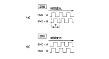
図6は、CRモータ正転時及び逆転時におけるリニア式エンコーダ11の2つの出力信号の波形を示したタイミングチャートである。
図6(a)及び図6(b)に示すように、CRモータ正転時及び逆転時のいずれの場合も、パルスENC−AとパルスENC−Bとは位相が90度だけ異なっている。CRモータ30が正転しているとき、即ち、キャリッジ28が主走査方向に移動しているときは、図6(a)に示すように、パルスENC−AはパルスENC−Bよりも90度だけ位相が進み、CRモータ30が逆転しているときは、図6(b)に示すように、パルスENC−AはパルスENC−Bよりも90度だけ位相が遅れる。そして、パルスENC−A及びパルスENC−Bの1周期Tは、キャリッジ28がリニア式エンコーダ用符号板12のスリット間隔を移動する時間に等しい。
【0042】
そして、リニア式エンコーダ11の出力パルスENC−A、ENC−Bの各々の立ち上がりエッジ、立ち上がりエッジが検出され、検出されたエッジの個数が計数され、この計数値に基づいてCRモータ30の回転位置が演算される。この計数はCRモータ30が正転しているときは1個のエッジが検出されると「+1」を加算し、逆転しているときは、1個のエッジが検出されると「−1」を加算する。パルスENC−A及びENC−Bの各々の周期は、リニア式エンコーダ用符号板12の、あるスリットがリニア式エンコーダ11を通過してから次のスリットがリニア式エンコーダ11を通過するまでの時間に等しく、かつ、パルスENC−AとパルスENC−Bとは位相が90度だけ異なっている。このため、上記計数のカウント値「1」はリニア式エンコーダ用符号板12のスリット間隔の1/4に対応する。これにより上記計数値にスリット間隔の1/4を乗算すれば、その乗算値に基づいて、計数値が「0」に対応する回転位置からのCRモータ30の移動量を求めることができる。このときリニア式エンコーダ11の解像度はリニア式エンコーダ用符号板12のスリットの間隔の1/4となる。
【0043】
一方、PFモータ31用のロータリ式エンコーダ13はロータリ式エンコーダ用符号板がPFモータ31の回転に応じて回転する回転円板である以外は、リニア式エンコーダ11と同様の構成となっており、2つの出力パルスENC−A、ENC−Bを出力し、かかる出力に基づいてPFモータ31の移動量を求めることができる。
【0044】
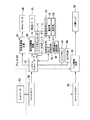
===カラーインクジェットプリンタの電気的構成例===
図7は、カラーインクジェットプリンタ20の電気的構成の一例を示すブロック図である。このカラーインクジェットプリンタ20は、コンピュータ90から供給された信号を受信するバッファメモリ50と、印刷データを格納するイメージバッファ52と、カラーインクジェットプリンタ20全体の動作を制御するシステムコントローラ54と、メインメモリ56と、EEPROM58とを備えている。システムコントローラ54には、さらに、キャリッジモータ30を駆動する主走査駆動回路61と、紙送りモータ31を駆動する副走査駆動回路62と、印刷ヘッド36を駆動するヘッド駆動回路63と、反射型光学センサ29の発光部38、受光部40を制御する反射型光学センサ制御回路65と、既述のリニア式エンコーダ11と、既述のロータリ式エンコーダ13と、が接続されている。また、反射型光学センサ制御回路65は、受光部40により受光される反射光から変換される電気信号を測定するための電気信号測定部66を備えている。
【0045】
コンピュータ90から転送された印刷データは、一旦、バッファメモリ50に蓄えられる。カラーインクジェットプリンタ20内では、システムコントローラ54が、バッファメモリ50から印刷データの中から必要な情報を読み取り、これに基づいて、主走査駆動回路61、副走査駆動回路62、ヘッド駆動回路63等に対して制御信号を送る。
【0046】
イメージバッファ52には、バッファメモリ50で受信された複数の色成分の印刷データが格納される。ヘッド駆動回路63は、システムコントローラ54からの制御信号に従って、イメージバッファ52から各色成分の印刷データを読出し、これに応じて印刷ヘッド36に設けられた各色のノズルアレイを駆動する。
【0047】
===印刷ヘッドのノズル配列例等===
図8は、印刷ヘッド36の下面におけるノズル配列を示す説明図である。この印刷ヘッド36は、副走査方向に沿った一直線上にそれぞれ配列されたブラックノズル列、イエローノズル列、マゼンタノズル列、シアンノズル列と、を有している。図に示すように、それぞれのノズル列は2列づつ設けられており、本明細書においては、各々のノズル列を、第一ブラックノズル列、第二ブラックノズル列、第一イエローノズル列、第二イエローノズル列、第一マゼンタノズル列、第二マゼンタノズル列、第一シアンノズル列、第二シアンノズル列と呼ぶ。
【0048】
ブラックノズル列(白丸で示す)は、360個のノズル#1〜#360を有している。これらのノズルのうち、奇数番目のノズル#1、#3、・・・、#359は第一ブラックノズル列に、偶数番目のノズル#2,#4、・・・、#360は第二ブラックノズル列に属している。第一ブラックノズル列のノズル#1、#3、・・・、#359は、副走査方向に沿って一定のノズルピッチk・Dで配置されている。ここで、Dは副走査方向のドットピッチであり、kは整数である。副走査方向のドットピッチDは、主走査ライン(ラスタライン)のピッチとも等しい。以下では、ノズルピッチk・Dを表す整数kを、単に「ノズルピッチk」と呼ぶ。図8の例では、ノズルピッチkは4ドットである。但し、ノズルピッチkは、任意の整数に設定することができる。
【0049】
また、第二ブラックノズル列のノズル#2,#4、・・・、#360も、また、副走査方向に沿って一定のノズルピッチk・D(ノズルピッチk=4)で配置されているが、図に示すように、各ノズルの副走査方向の位置は、第一ブラックノズル列の各ノズルの副走査方向の位置に比べてずれている。図8の例において、かかるずれ量は、1/2・k・D(k=4)である。
【0050】
また、上述した事項は、イエローノズル列(白三角で示す)、マゼンタノズル列(白四角で示す)、シアンノズル列(白菱形で示す)についても、同様である。すなわち、各ノズル列は、360個のノズル#1〜#360を有し、そのうち、奇数番目のノズル#1、#3、・・・、#359が第一列に、#2,#4、・・・、#360が第二列に属している。また、各々のノズル列は、副走査方向に沿って一定のノズルピッチk・Dで配置されており、第二列のノズルの副走査方向の位置は、第一列のノズルの副走査方向の位置に比べて、1/2・k・D(k=4)だけずれている。
【0051】
すなわち、印刷ヘッド36に配置されたノズル群は千鳥形状を構成しており、印刷時には、キャリッジ28とともに印刷ヘッド36が主走査方向に一定速度で移動している間に、各ノズルからインク滴が吐出される。但し、印刷方式によっては、すべてのノズルが常に使用されるとは限らず、一部のノズルのみが使用される場合もある。
【0052】
なお、前述した反射型光学センサ29は、印刷ヘッド36と共に、キャリッジ28に取付けられており、本実施の形態においては、図に示すように、反射型光学センサ29の副走査方向の位置は、前述したノズル#360の副走査方向の位置と一致している。
【0053】
<<印刷ヘッドのノズル配列とプラテンに設けられた溝との位置関係>>
次に、図9を用いて、前述した印刷ヘッド36のノズル配列と、プラテン26に設けられた溝との位置関係について説明する。図9は、印刷ヘッド36のノズル配列と、プラテン26に設けられた溝との位置関係を示す説明図である。
【0054】
プラテン26は、凹部と凸部とを有する。プラテン26は、この凹部として、主走査方向に沿って形成された2つの溝を有する。この2つの溝のうち、上流側の溝を上流側溝26bと呼び、下流側の溝を下流側溝26dと呼ぶ。これらの溝は、それぞれ主走査方向に印刷用紙Pの幅よりも長くなるように、プラテン26に形成されている。そして、これらの溝には、インクを吸収するための吸収体が設けられている。
【0055】
また、プラテン26は、凸部として、上流側支持部26aと、中央支持部26cと、下流側支持部26eとを有する。これらの支持部によって、印刷用紙Pが印刷ヘッド36に対向するように支持される。上流側支持部26aは、上流側溝26bよりも上流側で印刷用紙Pを支持し、中央支持部26cは、上流側溝26bと下流側溝26dとの間で印刷用紙Pを支持し、下流側支持部26eは、下流側溝26dよりも下流側で印刷用紙Pを支持する。
【0056】
印刷ヘッド36に配置された前述したノズル群は、それぞれ、上流側溝上ノズル群Nbと、中央ノズル群Ncと、下流側溝上ノズル群Ndとに分けられる。上流側溝上ノズル群Nbは、上流側溝26bと対向する位置に設けられているノズル群であって、本実施の形態においてはノズル♯261からノズル♯360が当該ノズル群である。中央ノズル群Ncは、中央支持部26cと対向する位置に設けられているノズル群であって、本実施の形態においてはノズル♯101からノズル♯260が当該ノズル群である。下流側溝上ノズル群Ndは、下流側溝26dと対向する位置に設けられているノズル群であって、本実施の形態においてはノズル♯1からノズル♯100が当該ノズル群である。
【0057】
キャリッジ28が主走査方向に移動することによって、印刷ヘッド36も主走査方向に移動するが、上流側溝26bと下流側溝26dが主走査方向に沿って形成されているので、上流側溝上ノズル群Nbは移動中も上流側溝26bに対向し続け、下流側溝上ノズル群Ndは移動中も下流側溝26dに対向し続けることが可能である。仮に、プラテン26上に印刷用紙Pが無い状態で上流側溝上ノズル群Nbからインクを吐出したとしても、吐出されたインクは上流側溝26bに着弾するため、プラテン26の支持部を汚さないので、その後に搬送される紙の裏面を汚さずに済む。同様に、仮にプラテン26上に印刷用紙Pが無い状態で下流側溝上ノズル群Ndからインクを吐出したとしても、吐出されたインクは下流側溝26dに着弾するため、プラテン26の支持部を汚さないので、その後に搬送される紙の裏面を汚さずに済む。さらに、それぞれの溝にはインク吸収体が設けられているため、溝に着弾したインクはインク吸収体に吸収され、紙の裏面がインクの跳ね返りによって汚れることが抑止される。
【0058】
後述するように、印刷用紙Pのうち紙送り方向上流側部分が印刷ヘッド36に対向する際には、印刷ヘッド30に設けられたインクを吐出するノズルとプラテン26の間に印刷用紙Pが無い状況が発生し得るため、プラテン26の支持部を汚さないように、インクを吐出するノズルを上流側溝上ノズル群Nb、中央ノズル群Nc、下流側溝上ノズル群Ndのうち、上流側溝上ノズル群Nbに制限する。
【0059】
同様に、印刷用紙Pのうち紙送り方向下流側部分が印刷ヘッド36に対向する際には、インクを吐出するノズルを下流側溝上ノズル群Ndに制限する。
【0060】
===第一の実施の形態===
次に、図10及び図11を用いて、本発明の第一の実施の形態について説明する。図10は、第一の実施の形態を説明するためのフローチャートである。図11については、後述する。
【0061】
先ず、最初に、ユーザがアプリケーションプログラム95等において印刷を行う旨を指示する(ステップS2)。本指示を受け取ったアプリケーションプログラム95が、印刷命令を発すると、コンピュータ90のプリンタドライバ96が、画像データをアプリケーションプログラム95から受け取り、これを各主走査時のドットの形成状態を示すラスタデータと副走査送り量を示すデータとを含む印刷データPDに変換する。さらに、プリンタドライバ96は、かかる印刷データPDを各種コマンドCOMとともに、カラーインクジェットプリンタ20に供給する。カラーインクジェットプリンタ20は、これらを、バッファメモリ50により受信した後に、イメージバッファ52又はシステムコントローラ54へ送信する。
【0062】
また、ユーザは印刷用紙Pのサイズや縁なし印刷を行う旨をユーザインターフェース表示モジュール101に指示することが可能である。ユーザによる当該指示は、ユーザインターフェース表示モジュール101により受け取られ、UIプリンタインターフェースモジュール102へ送られる。UIプリンタインターフェースモジュール102は、指示された命令を解釈して、カラーインクジェットプリンタ20へコマンドCOMを送信する。カラーインクジェットプリンタ20は、コマンドCOMをバッファメモリ50により受信した後に、システムコントローラ54へ送信する。
【0063】
カラーインクジェットプリンタ20は、システムコントローラ54に送信された命令に基づいて、副走査駆動回路62により紙送りモータ31を駆動させる等して、印刷用紙Pの給紙を行う(ステップS4)。
そして、システムコントローラ54は、印刷用紙Pを紙送り方向へ送りつつ、キャリッジ28を主走査方向に移動させて、キャリッジ28に備えられた印刷ヘッド36からインクを吐出して縁なし印刷を行う(ステップS6、ステップS8)。なお、印刷用紙Pの紙送り方向への送りは、副走査駆動回路62により紙送りモータ31を駆動させて、キャリッジ28の主走査方向への移動は、主走査駆動回路61によりキャリッジモータ30を駆動させて、印刷ヘッド36からのインクの吐出は、ヘッド駆動回路63により印刷ヘッド36を駆動させて、それぞれ行われる。
【0064】
カラーインクジェットプリンタ20は、ステップS6及びステップS8の動作を継続して行うが、例えば、主走査方向へのキャリッジ28の移動回数が所定回数に達した場合(ステップS10)には、次の主走査方向へのキャリッジ28の移動からは以下の動作を行う。
【0065】
システムコントローラ54は、反射型光学センサ制御回路65により、キャリッジ28に備えられた反射型光学センサ29を制御し、当該反射型光学センサ29の発光部38からプラテン26に向けて光を発する(ステップS12)。
【0066】
また、システムコントローラ54は、インクを吐出するために使用するノズルを、前記複数のノズルのうち所定のノズル、としての前記上流側溝上ノズル群Nbに、すなわち、ノズル♯261からノズル♯360に制限する。すなわち、本ステップ以降のインク吐出動作においては、システムコントローラ54によりヘッド駆動回路63を制御して、前記上流側溝上ノズル群Nb以外のノズルからのインクの吐出を行わないこととする。
【0067】
システムコントローラ54は、キャリッジ28を主走査方向に移動させて、キャリッジ28に備えられた印刷ヘッド36の前記上流側溝上ノズル群Nbからインクを吐出して縁なし印刷を行うとともに、プラテン26上の紙送り方向の所定の位置であって、主走査方向において異なる複数の位置、に向けて発光部38から光を発し、発せられた光を受光した受光部40の出力値に基づいて印刷用紙Pが光の進行方向にあるか否かを検知する(ステップS14)。
【0068】
なお、前述した通り、本実施の形態においては、反射型光学センサ29の紙送り方向の位置は、ノズル#360の紙送り方向の位置と一致しているから、前記紙送り方向の所定の位置は、ノズル#360の紙送り方向の位置にあたる。
【0069】
また、本実施の形態においては、キャリッジ28の主走査方向への移動中に、印刷用紙Pが光の進行方向にあるか否かを、常に検知する。すなわち、印刷用紙Pの端を上記発光部38から発光された光が遮ると、発光部38から発せられた光の入射先は、プラテン26から印刷用紙Pに変わるから、その反射光を受光した反射型光学センサ29の受光部40の出力値である電気信号の大きさは変化する。そして、この電気信号の大きさを電気信号測定部66により測定することにより、印刷用紙Pの端が前記光を通過したことを検知する。
【0070】
ステップS14におけるキャリッジ28の移動が完了したら、キャリッジ28の主走査方向への移動中に光の進行方向に印刷用紙Pが来ることがあったかどうかを、受光部40の出力値に基づいて判別する(ステップS16)。すなわち、印刷用紙Pの端のうち、紙送り方向上流側に位置する端が、紙送り方向の所定位置(本実施の形態においては、ノズル#360の紙送り方向の位置)を通過したかどうかを判定する。
【0071】
ステップS16の判別結果として、光の進行方向に印刷用紙Pが来ることがあった場合には、印刷用紙Pを紙送り方向へ送った後(ステップS18)、ステップS14に戻り、光の進行方向に印刷用紙Pが来ることがなくなるまで、ステップS14からステップS18の上述した動作を繰り返す。
ステップS16の判別結果として、光の進行方向に印刷用紙Pが来ることがなかった場合には、以下の動作を行う。
【0072】
図11を用いて、より詳細に、説明する。図11は、印刷ヘッド36のノズルと印刷用紙Pの位置関係を模式的に表した図である。
図11(a)乃至図11(c)の各図において、左側に示した小さな矩形は、印刷ヘッド36のノズルを表している。矩形内の番号は、ノズル番号であり、図8に示したノズル番号と対応している。なお、図11においては、説明を解りやすくするために、ブラックノズル列のみを示しており、また、図8において示した第一ブラックノズル列と第二ブラックノズル列を同一直線上に表している。図11において、ノズル#360の右側に示した円は、反射型光学センサ29を表している。前述したとおり、反射型光学センサ29の紙送り方向の位置は、ノズル#360の紙送り方向の位置と一致している。また、ブラックノズル列の右側には、印刷用紙Pの一部(下右端部)を表している。
【0073】
先ず、図11(a)に着目する。図11(a)は、上述したステップS14からステップS18の動作を繰り返し、ステップS16にて光の進行方向に印刷用紙Pが来ることがなかったと判別されたときの印刷ヘッド36のノズルと印刷用紙Pの位置関係を表している。図から明らかな通り、印刷ヘッド36と反射型光学センサ29を備えたキャリッジ28が主走査方向(本実施の形態においては、図中左から右への矢印方向)への移動中に反射型光学センサ29の発光部38から発せられる光の進行方向に印刷用紙Pが来ることはない。
【0074】
このようにステップS16の判別結果として、光の進行方向に印刷用紙Pが来ることがなかった場合には、図11(a)及び図11(b)に示すように印刷用紙Pを紙送り方向へ送る(ステップS20)。本実施の形態においては、25・D(Dはドットピッチ)分、印刷用紙Pを送っている。
【0075】
次に、キャリッジ28を主走査方向(本実施の形態においては、図11(b)中左から右の矢印方向)へ移動させて、キャリッジ28に備えられた印刷ヘッド36からインクを吐出して縁なし印刷を行う(ステップS24)が、当該印刷においては、印刷ヘッド36の複数ノズルのうち紙送り方向上流側に位置するノズルからのインクの吐出をさせないようにする。本実施の形態においては、紙送り方向最上流側に位置するノズル及び該ノズルからの紙送り方向の距離が所定距離内にあるノズル、からのインクの吐出をさせないようにしており、当該ノズルは、図11(b)にて点線で描かれた矩形により示される#353から#360までのノズルである。なお、前述したとおり、ステップS12以降のインク吐出動作においては、インク吐出のために使用するノズルをノズル♯261からノズル♯360に制限しているため、印刷用紙Pのうち紙送り方向上流側部分が、該紙送り方向の所定位置(本実施の形態においては、ノズル#360の紙送り方向の位置)を通過したと判定された際には、前記上流側溝上ノズル群Nb以外のノズルからの液体の吐出を行わないこととなる。したがって、図11(b)において、インクを吐出するノズルは#261から#352までのノズルである。
上記からも理解されるように、印刷ヘッド36のノズルからインクを吐出して縁なし印刷を行う(ステップS24)前に、インクの吐出をさせないノズルを決定するための手順(ステップS22)が必要である。インクの吐出をさせないノズルの具体的な決定方法については、後述する。
【0076】
次に、図11(b)及び図11(c)に示すように印刷用紙Pを紙送り方向へさらに送る(ステップS20)。本実施の形態においては、ここでも、25・D(Dはドットピッチ)分、印刷用紙Pを送っている。
【0077】
次に、キャリッジ28を主走査方向(本実施の形態においては、図11(b)中左から右の矢印方向)へ移動させて、キャリッジ28に備えられた印刷ヘッド36のノズルからインクを吐出して縁なし印刷を行う(ステップS24)が、当該印刷においても、印刷ヘッド36の複数ノズルのうち紙送り方向上流側に位置するノズルからのインクの吐出をさせないようにする。本実施の形態においては、紙送り方向最上流側に位置するノズル及び該ノズルからの紙送り方向の距離が所定距離内にあるノズル、からのインクの吐出をさせないようにしており、当該ノズルは、図11(c)にて点線で描かれた矩形により示される#340から#360までのノズルである。インクの吐出をさせないノズルは、ステップS24の前に決定される(ステップS22)。なお、上述したとおり、#1から#260までのノズルからもインクの吐出は行われない。
【0078】
その後、上記手順、すなわち、ステップS20からステップS24の手順、が何度か繰り返された後に、印刷用紙Pへの印刷が終了する(ステップS26)。そして、印刷用紙Pは副走査駆動回路62により駆動される紙送りモータ31により排紙される(ステップS28)。なお、ステップS20からステップS24の手順を何回繰り返して印刷を終了させるか、すなわち、インク吐出動作の終了タイミングの決定方法、については後述する。
【0079】
また、上記においては、光学センサとして反射型のものを用いることとしたが、これに限定されるものではない。例えば、前記発光部と前記受光部を主走査方向及び副走査方向に垂直な方向で対向するように、かつ、前記発光部と前記受光部が印刷用紙を挟むように配置してもよい。
【0080】
また、上記においては、ステップS10において、キャリッジ28の主走査方向への移動が所定回数に達した後に、印刷用紙の端が光を通過したことを検知し始めることとしたが、これに限定されるものではない。例えば、最初のキャリッジ28の主走査方向への移動から前記検知を始めても良いし、理想的な検知タイミングを演算等により求めて、検知回数を最小化してもよい。
【0081】
また、上記においては、ステップS20からステップS26のループ内で、ステップS22を通過する毎にインクを吐出させないノズルを決定することとしたが、一回目のステップS22において、一回目から最終回目までの当該ノズルを決定することとしてもよい。
【0082】
また、上記においては、ステップ12以降のインク吐出動作において、インクを吐出するために使用するノズルを上流側溝上ノズル群Nbに制限することとしたが、当該制限の開始はこのタイミングに限定されるものではない。
【0083】
===インクを吐出させないノズルの決定方法===
前述した通り、インクを吐出させないノズルは、ステップS22において、決定される。ここでは、図10及び図11を参照しつつ、かかるノズルの決定方法の一例について説明する。
先ず、上記実施の形態において既に説明したとおり、インクの吐出をさせないノズルは、紙送り方向最上流側に位置するノズル及び該ノズルからの紙送り方向の距離が所定距離内にあるノズルである。すなわち、図11の例では、ノズル#360及び当該ノズル#360からの紙送り方向の距離が所定距離内にあるノズルである。
【0084】
次に、所定距離について説明する。当該所定距離は、印刷用紙Pの累積紙送り量の増加に応じて、大きく設定される。本実施の形態において、所定距離は、印刷用紙Pのうち紙送り方向上流側部分が紙送り方向の所定位置(本実施の形態においては、ノズル#360の紙送り方向の位置)を通過した後の印刷用紙Pの累積紙送り量から所定量を減じた量とする。当該累積紙送り量は、図11(b)の例では、25・D(Dはドットピッチ)分の量、図11(c)の例では、(25・D+25・D)分の量である。
【0085】
前記所定量は、印刷用紙Pの紙送り方向上流側部分の紙送り方向における位置を検知する検知精度に応じて決定される。仮に、前記所定距離を単に前記累積紙送り量とすると、前記紙送り方向上流側部分の紙送り方向における位置を正確に検知できた場合には問題ないが、正確に検知できなかった場合には、インクを吐出させないノズルが印刷用紙Pに対向してしまう状況が発生し得る。かかる不都合を回避しある程度のマージンを確保するために、前記所定量が設定される。したがって、前記所定量は、前記検知精度が高いほど小さくなる。図11の例では、10・D分の量を、前記所定量としている。
【0086】
図11(b)及び図11(c)の例に上記決定方法を適用するとインクを吐出しないノズルは以下の通りとなる。
図11(b)の例では、累積紙送り量は25・D分の量であり、また、所定量は10・D分の量であった。したがって、所定距離は、15・D分の距離である。求めようとしているノズルは、ノズル#360及び当該ノズル#360からの紙送り方向の距離が所定距離内にあるノズルであり、#353から#360までのノズルが当該ノズルとなる。なお、ノズル#353のノズル#360からの紙送り方向の距離は、14・D分の距離となる。
【0087】
図11(c)の例では、累積紙送り量は50・D分の量であり、また、所定量は10・D分の量であった。したがって、所定距離は、40・D分の距離である。求めようとしているノズルは、ノズル#360及び当該ノズル#360からの紙送り方向の距離が所定距離内にあるノズルであり、#340から#360までのノズルが当該ノズルとなる。なお、ノズル#340のノズル#360からの紙送り方向の距離は、40・D分の距離となる。
【0088】
既に説明したとおり、図10で示したステップS20からステップS24の手順は、何度か繰り返される。上述した図11(b)と図11(c)に係るインクを吐出させないノズルの決定例は、それぞれ、一回目と、二回目のステップS22におけるノズルの決定例である。3回目以降のステップS22における当該ノズルの決定についても、同様の方法で行うことができる。
【0089】
===インク吐出動作終了タイミングの決定方法===
前述した通り、ステップS20からステップS24の手順、が何度か繰り返された後に、印刷用紙Pへの印刷が終了する(ステップS26)。本項では、ステップS20からステップS24の手順を何回繰り返して印刷を終了させるか、すなわち、インク吐出動作の終了タイミングの決定方法、について、図12を用いて説明する。図12は、インク吐出動作の終了タイミングの決定方法を説明するための説明図である。
【0090】
前項で説明したとおり、インクの吐出をさせないノズルは、紙送り方向最上流側に位置するノズル及び該ノズルからの紙送り方向の距離が所定距離内にあるノズルであり、印刷用紙Pの累積紙送り量の増加に応じて、当該所定距離は大きくなる。したがって、印刷用紙Pの累積紙送り量の増加に応じて、インクの吐出をさせないノズルの数が増加する。
そして、増加したインクを吐出させないノズルの数が、前記上流側溝上ノズル群Nbの数よりも多くなった場合には、印刷用紙Pへのインクの吐出動作を終了する。
【0091】
図12を用いて、例を挙げて説明する。図12においては、ステップS20からステップS24の手順の繰り返し回数(表中記号Aで表す)毎に、前記インクを吐出させないノズル(表中記号Bで表す)と、そのノズル数(表中記号Cで表す)と、を示している。また、あわせて、前述した上流側溝上ノズル(表中記号Dで表す)と、そのノズル数(表中記号Eで表す)と、ノズル数Eからノズル数Cを減じた値(表中記号Fで表す)も示している。なお、本実施の形態において、前記ノズル数Eからノズル数Cを減じた値Fは、各々の繰り返し回数Aにおいてインクを吐出させるノズルの数を表すこととなる。
【0092】
繰り返し回数A=1のときは、前述した図11(b)の例に相当し、ノズルBは#353から#360までのノズルとなる。そして、そのノズル数Cは、8である。また、上流側溝上ノズルDは、前述したとおり、#261から#360までのノズルであり、そのノズル数Eは100である。また、このときの値Fは92となる。
同様に、繰り返し回数A=2のときは、前述した図11(c)の例に相当し、ノズルBは#340から#360までのノズルとなる。そして、そのノズル数Cは、21である。また、上流側溝上ノズルDとそのノズル数Eは、繰り返し回数Aの値に関わらず、一定であり、上流側溝上ノズルDは#261から#360までのノズルであり、そのノズル数Eは100である。また、このときの値Fは79となる。
このように、インクを吐出させないノズル数Cは、繰り返し回数Aの増加に伴って増加していくのに対して、上流側ノズル数Eは一定なので、値Fは繰り返し回数Aの増加に伴って減少していく。
【0093】
そして、繰り返し回数Aがある回数に達すると、前記値Fが負の値となる。本実施の形態においては、図12に示すように、繰り返し回数A=8までは、値Fは正の値(F=4)をとり、繰り返し回数A=9において、値Fは負の値となる(F=−8)。
このことは、A=8まではインクを吐出させるノズルが存在する(例えば、A=8においては#261から#264までのノズルからインクを吐出することとなる)が、A=9以降はインクを吐出させるノズルが存在しなくなることを意味する。したがって、インクを吐出させないノズルの数が、前記上流側溝上ノズル群Nbの数よりも多くなった場合、すなわち、本実施形態においてA=9となった場合、には、印刷用紙Pへインクを吐出することなく、インクの吐出動作を終了することとする。
【0094】
このように、印刷用紙の累積紙送り量の増加に応じて前記所定距離を大きくし、インクの吐出をさせないノズルの数を増加させ、インクの吐出をさせないノズルの数が、前記上流側溝上ノズル群の数よりも多くなった場合には、印刷用紙へのインクの吐出動作を終了することにより、インクの吐出動作の終了タイミングを簡易に決定することができる。
【0095】
すなわち、背景技術の項で説明したとおり、インクの吐出動作を終了させるタイミングを決定する方法として、印刷ヘッドのノズルのピッチや、いわゆるオーバーラップ記録方式の採用の有無や、採用した場合には同一主走査ライン上のドット群を記録するためのノズル数等、の要素に基づいて前記タイミングを決定する方法が存するが、当該方法を採用すると、カラーインクジェットプリンタの機種毎に、又は、カラーインクジェットプリンタの設定毎に前記要素に係るデータベースを用意する手間が掛かる等、前記タイミングの決定は複雑なものとなる。
【0096】
そこで、前述したように、インクの吐出をさせないノズルの数が、前記上流側溝上ノズル群の数よりも多くなった場合に、印刷用紙へのインクの吐出動作を終了することとすれば、カラーインクジェットプリンタの機種等毎に上記のようなデータベースを用意することなく、インクの吐出動作の終了タイミングを簡易に決定することができる。
【0097】
なお、以上の処理を行うためのプログラムは、EEPROM58に格納されており、かかるプログラムはシステムコントローラ54により実行される。
【0098】
===その他の実施の形態===
以上、一実施形態に基づき本発明に係る液体吐出装置等を説明してきたが、上記した発明の実施の形態は、本発明の理解を容易にするためのものであり、本発明を限定するものではない。本発明は、その趣旨を逸脱することなく、変更、改良され得ると共に、本発明にはその等価物が含まれることは勿論である。
また、媒体として印刷用紙を例にとって説明したが、媒体として、フィルム、布、金属薄板等を用いてもよい。
【0099】
また、上記実施の形態においては、液体吐出装置の一例として印刷装置について説明したが、これに限定されるものではない。例えば、カラーフィルタ製造装置、染色装置、微細加工装置、半導体製造装置、表面加工装置、三次元造形機、液体気化装置、有機EL製造装置(特に高分子EL製造装置)、ディスプレイ製造装置、成膜装置、DNAチップ製造装置などに、本実施形態と同様の技術を適用しても良い。このような分野に本技術を適用しても、液体を媒体に向かって吐出することができるという特徴があるので、前述した効果を維持することができる。
【0100】
また、上記実施の形態においては、印刷装置の一例としてカラーインクジェットプリンタについて説明したが、これに限定されるものではなく、例えば、モノクロインクジェットプリンタについても適用可能である。
【0101】
また、上記実施の形態においては、液体の一例としてインクについて説明したが、これに限定されるものではない。例えば、金属材料、有機材料(特に高分子材料)、磁性材料、導電性材料、配線材料、成膜材料、加工液、遺伝子溶液などを含む液体(水も含む)をノズルから吐出してもよい。
【0102】
また、上記実施の形態では、印刷用紙のうち紙送り方向上流側部分が、紙送り方向の所定位置を通過したと判定された際には、前記複数のノズルのうち前記所定のノズル以外のノズルからの液体の吐出を行わないこととしたが、これに限定されるものではない。例えば、前記複数のノズルのうち前記所定のノズル以外のノズルからの液体の吐出を行うこととしてもよい。
ただし、インクを吐出させるノズルが存在しなくなる状況下で、インクの吐出動作を終了することができる点で上記実施の形態の方がより望ましい。
【0103】
また、上記実施の形態では、凹部を備え、印刷用紙を支持するためのプラテンを有し、前記複数のノズルのうち前記所定のノズルは、プラテンの凹部に対向することとしたが、これに限定されるものではない。
ただし、このように、前記複数のノズルのうち前記所定のノズルは、プラテンの凹部に対向する上流側溝上ノズル群であることとすれば、媒体支持部を汚さずに、その後に搬送される媒体の裏面を汚さずに済む等のメリットを有する点で、上記実施の形態の方がより望ましい。
【0104】
また、上記実施の形態においては、前記累積紙送り量から所定量を減じた量を前記所定距離とすることとしたが、これに限定されるものではない。例えば、前記累積紙送り量を前記所定距離としてもよい。
このようにすれば、印刷用紙の紙送り方向上流側部分の紙送り方向における位置を検知する際の検知誤差を考慮し、マージンを確保することが可能となる。
【0105】
また、上記実施の形態においては、前記所定量は、印刷用紙のうち紙送り方向上流側部分の紙送り方向における位置を検知する検知精度が高いほど小さいこととしたが、これに限定されるものではない。例えば、前記所定量に前記検知精度とは無関係な値を設定してもよい。
ただし、検知精度の大きさに応じてマージンの量を調整することにより、より効果的にインクを吐出させないノズルを決定することができる点で、上記実施の形態の方がより望ましい。
【0106】
また、上記実施の形態においては、印刷用紙の端のうち、紙送り方向上流側に位置する端が、紙送り方向の所定位置を通過したかどうかを判定し、この判定結果に基づいて、前記複数のノズルのうち、紙送り方向最上流側に位置するノズル及び該ノズルからの紙送り方向の距離が所定距離内にあるノズル、からの液体の吐出をさせないようにすることとしたが、これに限定されるものではない。例えば、印刷用紙のうち、紙送り方向上流側に位置する端以外の部分が、紙送り方向の所定位置を通過したかどうかを判定することとしてもよい。
ただし、より確実に、前記判定をすることができる点で、上記実施の形態の方が望ましい。
【0107】
また、上記実施の形態においては、印刷用紙を支持するためのプラテンと、プラテンに向けて光を発するための発光部と、前記発光部により発せられた光を受光するための受光部と、を備え、受光部の出力値に基づいて印刷用紙が発光部から発せられた光の進行方向にあるか否かを判別することにより、印刷用紙の端のうち、紙送り方向上流側に位置する端が、紙送り方向の所定位置を通過したかどうかを判定することとしたが、これに限定されるものではない。
ただし、より簡易に、印刷用紙の端のうち、紙送り方向上流側に位置する端が、紙送り方向の所定位置を通過したかどうかを判定することができる点で、上記実施の形態の方がより望ましい。
【0108】
また、上記実施の形態においては、プラテン上の紙送り方向の前記所定の位置であって、主走査方向において異なる複数の位置、に向けて発光部から光を発し、発せられた光を受光した受光部の出力値に基づいて印刷用紙が光の進行方向にあるか否かを判別することとしたが、これに限定されるものではない。例えば、プラテン上の紙送り方向の前記所定の位置であって、唯一の位置、に向けて発光部から光を発し、発せられた光を受光した受光部の出力値に基づいて印刷用紙が光の進行方向にあるか否かを判別することとしてもよい。
ただし、このようにすれば、印刷用紙が傾いている場合等であっても、確実に、印刷用紙のうち紙送り方向上流側部分が、紙送り方向の所定位置を通過したかどうかを判定することができる点で、上記実施の形態の方がより望ましい。
【0109】
また、上記実施の形態においては、主走査方向に移動可能なキャリッジに、発光部と受光部が設けられており、キャリッジを主走査方向に移動させながら、プラテン上の紙送り方向の前記所定の位置であって、主走査方向において異なる複数の位置、に向けて発光部から光を発し、発せられた光を受光した受光部の出力値に基づいて印刷用紙が光の進行方向にあるか否かを判別することとしたがこれに限定されるものではない。例えば、発光部と受光部の位置を固定とし、プラテン上の紙送り方向の前記所定の位置であって、主走査方向において異なる複数の位置、に向けて発光部から光を発し、発せられた光を受光した受光部の出力値に基づいて印刷用紙が光の進行方向にあるか否かを判別することとしてもよい。 ただし、このようにすれば、主走査方向において異なる複数の前記位置に向けて発光部から光を発する際に、前記位置毎に光を発する方向を変化させる必要がない点で、上記実施の形態の方がより望ましい。
【0110】
また、上記実施の形態においては、キャリッジは、印刷ヘッドを備えており、キャリッジを主走査方向に移動させながら、紙送り方向の前記所定の位置であって、主走査方向において異なる複数の位置、に向けて発光部から光を発し、発せられた光を受光した受光部の出力値に基づいて印刷用紙が光の進行方向にあるか否かを判別すると共に、印刷ヘッドに設けられたノズルからインクを吐出して印刷用紙に印刷を行うこととしたが、これに限定されるものではない。例えば、キャリッジと前記発光部及び前記受光部を、主走査方向に別個に移動可能とする構成としてもよい。
ただし、このようにすれば、キャリッジと前記発光部及び前記受光部の移動機構を共通化することができる点で、上記実施の形態の方が望ましい。
【0111】
また、上記実施の形態においては、縁なし印刷を行うこととしたが、これに限定されるものではない。
ただし、縁なし印刷の場合には、印刷用紙の全表面を対象として印刷を行うため、ノズル面の一部が印刷用紙に対向しない状態において印刷用紙に対向しないノズルからインクを吐出する状況が生じやすいから、上記手段によるメリットがより大きくなる。
===コンピュータシステム等の構成===
次に、本発明に係る実施形態の一例であるコンピュータシステムの実施形態について、図面を参照しながら説明する。
図13は、コンピュータシステムの外観構成を示した説明図である。コンピュータシステム1000は、コンピュータ本体1102と、表示装置1104と、プリンタ1106と、入力装置1108と、読取装置1110とを備えている。コンピュータ本体1102は、本実施形態ではミニタワー型の筐体に収納されているが、これに限られるものではない。表示装置1104は、CRT(Cathode Ray Tube:陰極線管)やプラズマディスプレイや液晶表示装置等が用いられるのが一般的であるが、これに限られるものではない。プリンタ1106は、上記に説明されたプリンタが用いられている。入力装置1108は、本実施形態ではキーボード1108Aとマウス1108Bが用いられているが、これに限られるものではない。読取装置1110は、本実施形態ではフレキシブルディスクドライブ装置1110AとCD−ROMドライブ装置1110Bが用いられているが、これに限られるものではなく、例えばMO(Magneto Optical)ディスクドライブ装置やDVD(Digital Versatile Disk)等の他のものであっても良い。
【0112】
図14は、図13に示したコンピュータシステムの構成を示すブロック図である。コンピュータ本体1102が収納された筐体内にRAM等の内部メモリ1202と、ハードディスクドライブユニット1204等の外部メモリがさらに設けられている。
【0113】
なお、以上の説明においては、プリンタ1106が、コンピュータ本体1102、表示装置1104、入力装置1108、及び、読取装置1110と接続されてコンピュータシステムを構成した例について説明したが、これに限られるものではない。例えば、コンピュータシステムが、コンピュータ本体1102とプリンタ1106から構成されても良く、コンピュータシステムが表示装置1104、入力装置1108及び読取装置1110のいずれかを備えていなくても良い。
【0114】
また、例えば、プリンタ1106が、コンピュータ本体1102、表示装置1104、入力装置1108、及び、読取装置1110のそれぞれの機能又は機構の一部を持っていても良い。一例として、プリンタ1106が、画像処理を行う画像処理部、各種の表示を行う表示部、及び、デジタルカメラ等により撮影された画像データを記録した記録メディアを着脱するための記録メディア着脱部等を有する構成としても良い。
【0115】
このようにして実現されたコンピュータシステムは、システム全体として従来システムよりも優れたシステムとなる。
【0116】
【発明の効果】
本発明によれば、液体の吐出動作の終了タイミングを簡易に決定可能とする液体吐出装置、コンピュータシステム、及び、液体吐出方法を実現することが可能となる。
【図面の簡単な説明】
【図1】本発明の一例としての印刷システムの構成を示すブロック図である。
【図2】カラーインクジェットプリンタ20の主要な構成の一例を示す概略斜視図である。
【図3】反射型光学センサ29の一例を説明するための模式図である。
【図4】インクジェットプリンタのキャリッジ28周辺の構成を示した図である。
【図5】キャリッジ28に取付けられたリニア式エンコーダ11の構成を模式的に示した説明図である。
【図6】CRモータ正転時及び逆転時におけるリニア式エンコーダ11の2つの出力信号の波形を示したタイミングチャートである。
【図7】カラーインクジェットプリンタ20の電気的構成の一例を示すブロック図である。
【図8】印刷ヘッド36の下面におけるノズル配列を示す説明図である。
【図9】印刷ヘッド36のノズル配列と、プラテン26に設けられた溝との位置関係を示す説明図である。
【図10】第一の実施の形態を説明するためのフローチャートである。
【図11】印刷ヘッド36のノズルと印刷用紙Pの位置関係を模式的に表した図である。
【図12】インク吐出動作の終了タイミングの決定方法を説明するための説明図である。
【図13】コンピュータシステムの外観構成を示した説明図である。
【図14】図13に示したコンピュータシステムの構成を示すブロック図である。
【符号の説明】
11 リニア式エンコーダ 12 リニア式エンコーダ用符号板
13 ロータリ式エンコーダ 20 カラーインクジェットプリンタ
21 CRT 22 用紙スタッカ
24 紙送りローラ 25 プーリ
26 プラテン 26a 上流側支持部
26b 上流側溝 26c 中央支持部
26d 下流側溝 26e 下流側支持部
28 キャリッジ 29 反射型光学センサ
30 キャリッジモータ 31 紙送りモータ
32 牽引ベルト 34 ガイドレール
36 印刷ヘッド 38 発光部
40 受光部 50 バッファメモリ
52 イメージバッファ 54 システムコントローラ
56 メインメモリ 58 EEPROM
61 主走査駆動回路 62 副走査駆動回路
63 ヘッド駆動回路 65 反射型光学センサ制御回路
66 電気信号測定部 90 コンピュータ
91 ビデオドライバ 95 アプリケーションプログラム
96 プリンタドライバ 97 解像度変換モジュール
98 色変換モジュール 99 ハーフトーンモジュール
100 ラスタライザ
101 ユーザインターフェース表示モジュール
102 UIプリンタインターフェースモジュール
1000 コンピュータシステム
1102 コンピュータ本体
1104 表示装置
1106 プリンタ
1108 入力装置
1108A キーボード
1108B マウス
1110 読取装置
1110A フレキシブルディスクドライブ装置
1110B CD−ROMドライブ装置
1202 内部メモリ
1204 ハードディスクドライブユニット
Nb 上流側溝上ノズル群
Nc 中央ノズル群
Nd 下流側溝上ノズル群[0001]
BACKGROUND OF THE INVENTION
The present invention relates to a liquid ejection apparatus, a computer system, and a liquid ejection method.
[0002]
[Background]
A color ink jet printer which is a typical liquid ejecting apparatus is already well known. This color inkjet printer includes a print head as an example of an ink jet type ejection head that ejects ink as an example of liquid from nozzles, and ejects ink onto printing paper as an example of a medium to thereby print images and characters. Etc. are recorded.
[0003]
The print head is supported by the carriage with the nozzle surface on which the nozzles are formed facing the print paper, and moves in the width direction of the print paper along the guide member (main scan) and synchronizes with this main scan. Then, ink is ejected.
[0004]
Further, when the printing paper feeding operation and the ink ejection operation are repeatedly performed to perform printing on the printing paper, a state in which a part of the nozzle surface does not face the printing paper immediately before the end of printing occurs. In such a state, if ink is ejected from a nozzle that does not face the printing paper, the ink is wasted.
[0005]
As a measure for solving the inconvenience, it is determined whether or not the upstream portion in the paper feeding direction of the printing paper has passed a predetermined position in the paper feeding direction, and based on the determination result, among the plurality of nozzles, It is effective to prevent liquid from being ejected from the nozzle located on the most upstream side in the paper feed direction and the nozzle in which the distance in the paper feed direction from the nozzle is within a predetermined distance.
[0006]
On the other hand, when the upstream portion of the printing paper in the paper feeding direction passes through a predetermined position in the paper feeding direction, the printing operation is almost finished, and it is necessary to determine the timing for ending the liquid ejection operation. There is. As a method for determining such timing, the pitch of the nozzles of the print head, the presence or absence of the so-called overlap recording method, the number of nozzles for recording a group of dots on the same main scanning line when employed, A method of determining based on the above elements is conceivable. However, the determination by this method takes time and effort to prepare a database related to each element for each color ink jet printer model or for each setting of the color ink jet printer. The timing determination is complicated.
[0007]
[Patent Document 1]
JP-A-5-69608
[0008]
[Problems to be solved by the invention]
The present invention has been made in view of such problems, and an object of the present invention is to realize a liquid ejection apparatus, a computer system, and a liquid ejection method that can easily determine the end timing of the liquid ejection operation. There is to do.
[0009]
[Means for Solving the Problems]
The main present invention has a plurality of nozzles for discharging a liquid and has a movable discharge head and a feed mechanism for feeding a medium in a predetermined feed direction. A liquid ejection device comprising a sensor that detects an upstream end of the medium in the feeding direction, based on a detection result of the sensor, Upstream of the medium in the feed direction Side edge But, Of the plurality of nozzles, In the feed direction The nozzle located on the most upstream side It has passed After being determined, Among the plurality of nozzles, the feed direction of The nozzle located on the most upstream side and the distance in the feed direction from the nozzle are within a predetermined distance. All of Let the liquid discharge from the nozzle. The predetermined distance is a value obtained by subtracting a predetermined value from the cumulative feed amount of the medium after it is determined that the upstream end of the medium in the feed direction has passed through the nozzle located on the most upstream side in the feed direction. The cumulative feed amount of the medium by setting as According to the increase of , Increase the predetermined distance Setting Shi The Increase the number of nozzles that do not discharge the liquid, Determining the number of nozzles that do not cause the liquid to be ejected; The number of nozzles that do not discharge the liquid is a predetermined nozzle among the plurality of nozzles number And more By judging The liquid discharge apparatus is characterized in that the liquid discharge operation to the medium is terminated.
Other features of the present invention will become apparent from the description of the present specification and the accompanying drawings.
[0010]
DETAILED DESCRIPTION OF THE INVENTION
=== Summary of disclosure ===
At least the following will be made clear by the description of the present specification and the accompanying drawings.
A plurality of nozzles for discharging liquid, a movable discharge head, and a feed mechanism for feeding the medium in a predetermined feed direction, wherein the upstream side portion of the medium in the feed direction is It is determined whether or not a predetermined position in the feed direction has been passed. Based on the determination result, a nozzle located on the most upstream side in the feed direction among the plurality of nozzles and a distance in the feed direction from the nozzle are predetermined. In a liquid ejecting apparatus that prevents liquid from being ejected from nozzles within a distance, the predetermined distance is increased in accordance with an increase in the cumulative paper feed amount of the medium, and the number of nozzles that do not eject liquid is determined. When the number of nozzles that are increased and do not discharge the liquid is greater than the number of predetermined nozzles among the plurality of nozzles, the operation of discharging the liquid onto the medium is terminated. You A liquid ejection apparatus.
[0011]
The predetermined distance is increased in accordance with an increase in the accumulated paper feed amount of the medium, the number of nozzles that do not discharge the liquid is increased, and the number of nozzles that do not discharge the liquid is a predetermined number of the plurality of nozzles. When the number of nozzles is larger than the number of nozzles, the liquid discharge operation end timing can be easily determined by ending the liquid discharge operation to the medium.
[0012]
Further, when it is determined that the upstream portion of the medium in the feeding direction has passed a predetermined position in the feeding direction, liquid is discharged from nozzles other than the predetermined nozzle among the plurality of nozzles. It is good also as not doing.
In this way, the liquid discharge operation can be completed in a situation where there is no nozzle for discharging the liquid.
[0013]
Moreover, it is good also as having a medium support part provided with a recessed part and supporting the said medium, and the said predetermined nozzle facing the said recessed part of the said medium support part.
In this way, since the medium support portion is not soiled, there is an advantage that it is not necessary to stain the back surface of the medium conveyed thereafter.
[0014]
Further, an amount obtained by subtracting a predetermined amount from the accumulated paper feed amount may be set as the predetermined distance.
In this way, it is possible to secure a margin in consideration of the detection error when detecting the position in the feed direction of the upstream portion of the medium in the feed direction.
[0015]
The predetermined amount may be smaller as the detection accuracy for detecting the position of the upstream portion in the feed direction in the feed direction is higher.
In this way, it is possible to determine a nozzle that does not eject liquid more effectively by adjusting the amount of margin according to the magnitude of detection accuracy.
[0016]
In addition, it is determined whether an end located on the upstream side in the feeding direction among the ends of the medium has passed a predetermined position in the feeding direction, and based on the determination result, among the plurality of nozzles, It is possible to prevent the liquid from being discharged from the nozzle located on the most upstream side in the feed direction and the nozzle in which the distance in the feed direction from the nozzle is within a predetermined distance.
In this way, the determination can be made more reliably.
[0017]
A medium supporting unit for supporting the medium; a light emitting unit for emitting light toward the medium supporting unit; and a light receiving sensor for receiving the light emitted by the light emitting unit, By determining whether or not the medium is in the traveling direction of the light emitted from the light emitting means based on the output value of the light receiving sensor, the end located on the upstream side in the feeding direction among the ends of the medium However, it may be determined whether or not it has passed a predetermined position in the feed direction.
In this way, it is possible to more easily determine whether the end located on the upstream side in the feed direction among the ends of the medium has passed a predetermined position in the feed direction.
[0018]
Further, the light receiving unit that emits the light from the light emitting unit toward the predetermined position in the feeding direction on the medium support unit and is different in a main scanning direction, and receives the emitted light. Based on the output value of the sensor, it may be determined whether or not the medium is in the traveling direction of the light.
In this way, even when the medium is tilted, it is possible to reliably determine whether or not the upstream portion of the medium in the feed direction has passed a predetermined position in the feed direction. it can
The moving member movable in the main scanning direction is provided with the light emitting means and the light receiving sensor, and moving the moving member in the main scanning direction while moving the predetermined direction in the feeding direction on the medium support unit. The light is emitted from the light emitting means toward a plurality of different positions in the main scanning direction, and the medium advances the light based on an output value of the light receiving sensor that has received the emitted light. It may be determined whether or not it is in the direction.
In this way, when light is emitted from the light emitting means toward a plurality of different positions in the main scanning direction, there is no need to change the light emitting direction for each position.
[0019]
The moving member includes the ejection head, and moves the moving member in the main scanning direction toward the predetermined positions in the feeding direction and different positions in the main scanning direction. And determining whether the medium is in the light traveling direction based on an output value of the light receiving sensor that has emitted the light from the light emitting means and received the emitted light, and is provided in the ejection head. The liquid may be discharged from the nozzle to the medium.
If it does in this way, the movement mechanism of the said moving member, the said light emission means, and the said light reception sensor can be made shared.
[0020]
The liquid may be discharged over the entire surface of the medium.
In such a case, a situation in which liquid is easily discharged from a nozzle that does not face the medium in a state where a part of the nozzle surface does not face the medium is likely to occur.
[0021]
The liquid may be ink, and the liquid ejecting apparatus may be a printing apparatus that performs printing on a printing medium that is the medium by ejecting ink from the nozzle.
In such a case, it is possible to realize a printing apparatus that exhibits the effects described above.
[0022]
A plurality of nozzles for discharging liquid; a movable discharge head; a feed mechanism for feeding a medium in a predetermined feed direction; a medium support for supporting the medium; and the medium support A light emitting means for emitting light toward the part, and a light receiving sensor for receiving the light emitted by the light emitting means, and the medium is output from the light emitting means based on an output value of the light receiving sensor. By determining whether or not the emitted light is in the traveling direction, it is determined whether or not the end of the medium positioned upstream of the feeding direction has passed a predetermined position in the feeding direction. Based on the determination result, liquid is not ejected from the nozzle located on the most upstream side in the feed direction and the nozzle in the feed direction within the predetermined distance from the nozzle among the plurality of nozzles. To do In the body discharge device, the predetermined distance is increased in accordance with an increase in the cumulative paper feed amount of the medium, the number of nozzles that do not discharge the liquid is increased, and the number of nozzles that do not discharge the liquid is the plurality When the number of nozzles exceeds the predetermined number of nozzles, the operation of discharging the liquid onto the medium is terminated, and the upstream portion of the medium in the feed direction moves to a predetermined position in the feed direction. When it is determined that it has passed, it does not discharge liquid from nozzles other than the predetermined nozzle among the plurality of nozzles, includes a concave portion, and has a medium support portion for supporting the medium, The predetermined nozzle faces the concave portion of the medium support portion, and an amount obtained by subtracting a predetermined amount from the accumulated paper feed amount is set as the predetermined distance, and the predetermined amount is the feed direction of the upstream portion in the feed direction. Detect position in The light emitting means, the light receiving sensor, and the ejection head are provided on a moving member that is smaller as the detection accuracy is higher and is movable in the main scanning direction, and the moving member is moved in the main scanning direction while moving the moving member in the main scanning direction. An output of the light receiving sensor that emits the light from the light emitting means toward the predetermined position in the feeding direction on the medium support portion and is different in the main scanning direction, and receives the emitted light. Based on the value, it is determined whether or not the medium is in the traveling direction of the light, and the liquid is ejected from the nozzles provided in the ejection head to the medium, and the liquid is ejected on the entire surface of the medium. The liquid is an ink, and the liquid ejecting apparatus is a printing apparatus that performs printing on a printing medium as the medium by ejecting ink from the nozzles. Can also be realized.
Since the liquid ejection device thus realized has all the effects described above, the object of the present invention can be achieved most effectively.
[0023]
A computer main body, a display device connectable to the computer main body, and a liquid discharge device connectable to the computer main body, comprising a plurality of nozzles for discharging liquid, a movable discharge head, and a medium A feed mechanism for feeding in a predetermined feed direction, and determining whether or not the upstream portion of the medium in the feed direction has passed a predetermined position in the feed direction, and based on the determination result, Among the plurality of nozzles, a liquid ejection device that prevents ejection of liquid from a nozzle located on the most upstream side in the feeding direction and a nozzle whose distance in the feeding direction from the nozzle is within a predetermined distance. The predetermined distance is increased in accordance with an increase in the cumulative paper feed amount of the medium, the number of nozzles that do not discharge the liquid is increased, and the number of nozzles that do not discharge the liquid is It is also possible to realize a computer system comprising a liquid ejection device that terminates a liquid ejection operation to the medium when the number of nozzles exceeds a predetermined number among the plurality of nozzles. is there.
The computer system realized in this way is a system superior to the conventional system as a whole system.
Also, the following liquid ejection method can be realized. It is determined whether the upstream portion of the medium in the feed direction has passed a predetermined position in the feed direction, and based on the determination result, a nozzle located on the most upstream side in the feed direction among a plurality of nozzles, and In the liquid ejection method for preventing liquid from being ejected from a nozzle whose distance in the feeding direction from the nozzle is within a predetermined distance, the predetermined distance is increased in accordance with an increase in the accumulated paper feed amount of the medium. When the number of nozzles that do not discharge the liquid is increased and the number of nozzles that do not discharge the liquid is larger than the number of the predetermined nozzles among the plurality of nozzles, A liquid discharge method, comprising: terminating a liquid discharge operation.
[0024]
=== Example of Overall Configuration of Apparatus ===
FIG. 1 is a block diagram showing a configuration of a printing system as an example of the present invention. This printing system includes a
[0025]
In the
[0026]
When the
[0027]
The
[0028]
The color-converted multi-gradation data has, for example, 256 gradation values. The
[0029]
The user
[0030]
The UI
[0031]
The
[0032]
FIG. 2 is a schematic perspective view illustrating an example of a main configuration of the
[0033]
The printing paper P is taken up by the
[0034]
=== Configuration Example of Reflective Optical Sensor ===
FIG. 3 is a schematic diagram for explaining an example of the reflective
[0035]
In the above description, as shown in the drawing, the
[0036]
In the above, in order to obtain the intensity of the received reflected light, the magnitude of the electric signal is measured after converting the reflected light into an electric signal. However, the present invention is not limited to this. It is only necessary to measure the output value of the light receiving sensor according to the intensity of the reflected light.
[0037]
=== Example of configuration around carriage ===
Next, the configuration around the carriage will be described. FIG. 4 is a diagram showing a configuration around the
The ink jet printer shown in FIG. 4 includes a paper feed motor (hereinafter also referred to as a PF motor) 31 that feeds paper as an example of a feed mechanism, and a
[0038]
Next, the
The
[0039]
When the voltage VCC is applied to both ends of the
[0040]
The parallel light that has passed through the linear
[0041]
FIG. 6 is a timing chart showing waveforms of two output signals of the
As shown in FIGS. 6 (a) and 6 (b), the pulse ENC-A and the pulse ENC-B differ in phase by 90 degrees in both cases of CR motor forward rotation and reverse rotation. When the
[0042]
Then, the rising edge and the rising edge of each of the output pulses ENC-A and ENC-B of the
[0043]
On the other hand, the
[0044]
=== Example of an electrical configuration of a color inkjet printer ===
FIG. 7 is a block diagram illustrating an example of an electrical configuration of the
[0045]
The print data transferred from the
[0046]
The
[0047]
=== Example of nozzle arrangement of print head, etc. ===
FIG. 8 is an explanatory diagram showing the nozzle arrangement on the lower surface of the
[0048]
The black nozzle row (indicated by white circles) has 360
[0049]
The
[0050]
The same applies to the yellow nozzle row (indicated by white triangles), the magenta nozzle row (indicated by white squares), and the cyan nozzle row (indicated by white rhombuses). That is, each nozzle row has 360
[0051]
That is, the nozzle group arranged in the
[0052]
The reflective
[0053]
<< Positional relationship between nozzle array of print head and grooves provided on platen >>
Next, the positional relationship between the nozzle arrangement of the
[0054]
The
[0055]
Further, the
[0056]
The above-described nozzle groups arranged in the
[0057]
As the
[0058]
As will be described later, when the upstream portion of the print paper P in the paper feed direction faces the
[0059]
Similarly, when the downstream portion in the paper feed direction of the printing paper P faces the
[0060]
=== First Embodiment ===
Next, the first embodiment of the present invention will be described with reference to FIGS. FIG. 10 is a flowchart for explaining the first embodiment. FIG. 11 will be described later.
[0061]
First, the user instructs to perform printing in the
[0062]
Further, the user can instruct the user
[0063]
Based on the command transmitted to the
Then, the
[0064]
The
[0065]
The
[0066]
Further, the
[0067]
The
[0068]
Note that, as described above, in the present embodiment, the position of the reflective
[0069]
In the present embodiment, it is always detected whether or not the printing paper P is in the light traveling direction while the
[0070]
When the movement of the
[0071]
As a result of the determination in step S16, if the printing paper P has come in the light traveling direction, the printing paper P is fed in the paper feeding direction (step S18), and then the process returns to step S14, and the light traveling direction. Until the printing paper P no longer comes, the above-described operation from step S14 to step S18 is repeated.
As a result of the determination in step S16, when the printing paper P does not come in the light traveling direction, the following operation is performed.
[0072]
This will be described in more detail with reference to FIG. FIG. 11 is a diagram schematically showing the positional relationship between the nozzles of the
In each of FIGS. 11A to 11C, the small rectangle shown on the left side represents the nozzle of the
[0073]
First, attention is focused on FIG. FIG. 11A repeats the operations from step S14 to step S18 described above, and the nozzles of the
[0074]
As described above, when the printing paper P does not come in the light traveling direction as a result of determination in step S16, the printing paper P is fed in the paper feed direction as shown in FIGS. 11 (a) and 11 (b). (Step S20). In the present embodiment, the printing paper P is fed by 25 · D (D is a dot pitch).
[0075]
Next, the
As can be understood from the above, a procedure (step S22) for determining the nozzles from which ink is not ejected is required before ink is ejected from the nozzles of the
[0076]
Next, as shown in FIGS. 11B and 11C, the printing paper P is further fed in the paper feeding direction (step S20). In this embodiment, the printing paper P is also fed by 25 · D (D is a dot pitch).
[0077]
Next, the
[0078]
Thereafter, after the above procedure, that is, the procedure from step S20 to step S24, is repeated several times, printing on the printing paper P is completed (step S26). Then, the printing paper P is discharged by the
[0079]
In the above description, a reflection type optical sensor is used. However, the present invention is not limited to this. For example, the light emitting unit and the light receiving unit may be arranged so as to face each other in a direction perpendicular to the main scanning direction and the sub scanning direction, and the light emitting unit and the light receiving unit sandwich the printing paper.
[0080]
In the above description, in step S10, after the movement of the
[0081]
In the above, in the loop from step S20 to step S26, the nozzle that does not eject ink is determined every time it passes step S22. However, in the first step S22, from the first time to the last time. The nozzle may be determined.
[0082]
In the above description, in the ink ejection operation after
[0083]
=== Method for Determining No-jet Nozzle ===
As described above, the nozzles that do not eject ink are determined in step S22. Here, an example of such a nozzle determination method will be described with reference to FIGS. 10 and 11.
First, as already described in the above embodiment, the nozzles that do not eject ink are nozzles located on the most upstream side in the paper feed direction and nozzles having a distance in the paper feed direction from the nozzle within a predetermined distance. That is, in the example of FIG. 11, the
[0084]
Next, the predetermined distance will be described. The predetermined distance is set to be larger as the accumulated paper feed amount of the printing paper P increases. In the present embodiment, the predetermined distance is after the upstream portion of the printing paper P in the paper feeding direction passes a predetermined position in the paper feeding direction (in this embodiment, the position of the
[0085]
The predetermined amount is determined according to the detection accuracy for detecting the position of the upstream portion of the printing paper P in the paper feeding direction. If the predetermined distance is simply the accumulated paper feed amount, there is no problem if the position of the upstream portion in the paper feed direction in the paper feed direction can be accurately detected. A situation may occur in which a nozzle that does not eject ink faces the printing paper P. In order to avoid such inconvenience and to secure a certain margin, the predetermined amount is set. Therefore, the predetermined amount decreases as the detection accuracy increases. In the example of FIG. 11, the amount of 10 · D is the predetermined amount.
[0086]
When the above determination method is applied to the examples of FIGS. 11B and 11C, nozzles that do not eject ink are as follows.
In the example of FIG. 11B, the accumulated paper feed amount is an amount for 25 · D, and the predetermined amount is an amount for 10 · D. Therefore, the predetermined distance is a distance of 15 · D. The nozzles to be obtained are nozzles # 360 and nozzles in which the distance in the paper feed direction from the
[0087]
In the example of FIG. 11C, the cumulative paper feed amount is an amount for 50 · D, and the predetermined amount is an amount for 10 · D. Therefore, the predetermined distance is a distance of 40 · D. The nozzles to be obtained are nozzles # 360 and nozzles whose distance in the paper feed direction from the
[0088]
As already described, the procedure from step S20 to step S24 shown in FIG. 10 is repeated several times. The above-described determination examples of the nozzles that do not eject ink according to FIGS. 11B and 11C are the determination examples of the nozzles in the first and second steps S22, respectively. The determination of the nozzle in step S22 after the third time can also be performed by the same method.
[0089]
=== Method for Determining End Timing of Ink Ejection Operation ===
As described above, after the procedure from step S20 to step S24 is repeated several times, printing on the printing paper P is completed (step S26). In this section, how many times the procedure from step S20 to step S24 is repeated to end printing, that is, a method for determining the end timing of the ink ejection operation will be described with reference to FIG. FIG. 12 is an explanatory diagram for explaining a method of determining the end timing of the ink ejection operation.
[0090]
As described in the previous section, the nozzles that do not eject ink are nozzles located on the most upstream side in the paper feed direction and nozzles in which the distance in the paper feed direction from the nozzles is within a predetermined distance. As the feed amount increases, the predetermined distance increases. Accordingly, the number of nozzles that do not eject ink increases as the accumulated paper feed amount of the printing paper P increases.
When the number of nozzles that do not eject the increased ink is greater than the number of the upstream groove nozzle group Nb, the operation of ejecting ink onto the printing paper P is terminated.
[0091]
An example will be described with reference to FIG. In FIG. 12, each time the procedure from step S20 to step S24 is repeated (represented by symbol A in the table), the nozzle that does not eject the ink (represented by symbol B in the table) and the number of nozzles (represented by symbol C in the table). ). In addition, the upstream groove nozzle (represented by symbol D in the table), the number of nozzles (represented by symbol E in the table), and the value obtained by subtracting the nozzle number C from the nozzle number E (symbol F in the table) It is also shown. In the present embodiment, a value F obtained by subtracting the number of nozzles C from the number of nozzles E represents the number of nozzles that eject ink at each repetition count A.
[0092]
When the number of repetitions A = 1, this corresponds to the example of FIG. 11B described above, and the nozzles B are nozzles # 353 to # 360. The number of nozzles C is 8. Further, the upstream groove upper nozzle D is the nozzles from # 261 to # 360 as described above, and the number E of the nozzles is 100. The value F at this time is 92.
Similarly, when the number of repetitions A = 2, it corresponds to the example of FIG. 11C described above, and the nozzles B are nozzles # 340 to # 360. The number C of nozzles is 21. Further, the upstream groove nozzle D and the number E of nozzles thereof are constant regardless of the value of the repetition count A, and the upstream groove nozzle D is
Thus, the number of nozzles C that do not eject ink increases as the number of repetitions A increases, whereas the number of upstream nozzles E is constant, so the value F increases as the number of repetitions A increases. Decrease.
[0093]
When the number of repetitions A reaches a certain number, the value F becomes a negative value. In the present embodiment, as shown in FIG. 12, the value F takes a positive value (F = 4) until the number of repetitions A = 8, and the value F is a negative value at the number of repetitions A = 9. (F = -8).
This means that there are nozzles that eject ink until A = 8 (for example, when A = 8, ink is ejected from nozzles # 261 to # 264), but after A = 9, ink is ejected. This means that there is no longer any nozzle that discharges water. Therefore, when the number of nozzles that do not eject ink is larger than the number of the upstream groove group Nb, that is, when A = 9 in this embodiment, ink is applied to the printing paper P. The ink ejection operation is finished without ejection.
[0094]
As described above, the predetermined distance is increased in accordance with an increase in the cumulative paper feed amount of the printing paper, the number of nozzles that do not eject ink is increased, and the number of nozzles that do not eject ink is determined by the nozzle on the upstream side groove. When the number exceeds the number of groups, the ink discharge operation end timing can be easily determined by ending the ink discharge operation on the printing paper.
[0095]
In other words, as described in the background section, the method for determining the timing for terminating the ink ejection operation is the same as the nozzle pitch of the print head, whether or not a so-called overlap recording method is employed, and when employed. There is a method for determining the timing based on factors such as the number of nozzles for recording a group of dots on the main scanning line. If this method is employed, the color ink jet printer can be used for each type of color ink jet printer. The determination of the timing is complicated, for example, it takes time to prepare a database related to the element for each setting.
[0096]
Therefore, as described above, if the number of nozzles that do not eject ink is larger than the number of nozzle groups on the upstream groove, the ink ejection operation on the printing paper is terminated. The end timing of the ink ejection operation can be easily determined without preparing a database as described above for each type of inkjet printer.
[0097]
Note that a program for performing the above processing is stored in the
[0098]
=== Other Embodiments ===
As mentioned above, although the liquid discharge apparatus etc. which concern on this invention have been demonstrated based on one Embodiment, Embodiment mentioned above is for making an understanding of this invention easy, and limits this invention. is not. The present invention can be changed and improved without departing from the gist thereof, and the present invention includes the equivalents thereof.
Further, although the printing paper has been described as an example of the medium, a film, a cloth, a thin metal plate, or the like may be used as the medium.
[0099]
In the above-described embodiment, the printing apparatus has been described as an example of the liquid ejection apparatus. However, the present invention is not limited to this. For example, color filter manufacturing apparatus, dyeing apparatus, fine processing apparatus, semiconductor manufacturing apparatus, surface processing apparatus, three-dimensional modeling machine, liquid vaporizer, organic EL manufacturing apparatus (particularly polymer EL manufacturing apparatus), display manufacturing apparatus, film formation You may apply the same technique as this embodiment to an apparatus, a DNA chip manufacturing apparatus, etc. Even if the present technology is applied to such a field, since the liquid can be ejected toward the medium, the above-described effects can be maintained.
[0100]
In the above-described embodiment, a color inkjet printer has been described as an example of a printing apparatus. However, the present invention is not limited to this, and can be applied to, for example, a monochrome inkjet printer.
[0101]
In the above embodiment, ink has been described as an example of a liquid, but the present invention is not limited to this. For example, a liquid (including water) containing a metal material, an organic material (particularly a polymer material), a magnetic material, a conductive material, a wiring material, a film forming material, a processing solution, a gene solution, or the like may be discharged from a nozzle. .
[0102]
In the above embodiment, when it is determined that the upstream portion of the printing paper in the paper feeding direction has passed a predetermined position in the paper feeding direction, nozzles other than the predetermined nozzle among the plurality of nozzles. However, the present invention is not limited to this. For example, liquid may be discharged from nozzles other than the predetermined nozzle among the plurality of nozzles.
However, the above embodiment is more preferable in that the ink ejection operation can be completed under the situation where there is no nozzle for ejecting ink.
[0103]
Further, in the above embodiment, the platen is provided with a recess and supports the printing paper, and the predetermined nozzle among the plurality of nozzles faces the recess of the platen. Is not to be done.
However, as described above, if the predetermined nozzle among the plurality of nozzles is an upstream grooved nozzle group facing the concave portion of the platen, the medium that is conveyed afterwards without contaminating the medium support section. The above embodiment is more desirable in that it has the merit that the back surface of the film does not need to be stained.
[0104]
In the above embodiment, an amount obtained by subtracting a predetermined amount from the accumulated paper feed amount is set as the predetermined distance. However, the present invention is not limited to this. For example, the accumulated paper feed amount may be set as the predetermined distance.
In this way, it is possible to secure a margin in consideration of detection errors when detecting the position of the upstream portion of the print paper in the paper feed direction in the paper feed direction.
[0105]
In the above embodiment, the predetermined amount is smaller as the detection accuracy of detecting the position in the paper feeding direction of the upstream portion of the printing paper in the paper feeding direction is higher. However, the predetermined amount is limited to this. is not. For example, a value irrelevant to the detection accuracy may be set for the predetermined amount.
However, the above embodiment is more preferable in that a nozzle that does not eject ink more effectively can be determined by adjusting the amount of margin according to the magnitude of detection accuracy.
[0106]
Further, in the above-described embodiment, it is determined whether or not the end of the printing paper that is located upstream in the paper feeding direction has passed a predetermined position in the paper feeding direction, and based on the determination result, Among the plurality of nozzles, the nozzle located on the most upstream side in the paper feed direction and the nozzle in which the distance in the paper feed direction from the nozzle is within a predetermined distance are prevented from discharging liquid. It is not limited to. For example, it may be determined whether or not a portion of the printing paper other than the edge located upstream in the paper feeding direction has passed a predetermined position in the paper feeding direction.
However, the above embodiment is preferable in that the determination can be made more reliably.
[0107]
In the above embodiment, a platen for supporting the printing paper, a light emitting unit for emitting light toward the platen, and a light receiving unit for receiving the light emitted by the light emitting unit. And determining whether or not the printing paper is in the traveling direction of the light emitted from the light emitting unit based on the output value of the light receiving unit. However, it has been determined whether or not it has passed a predetermined position in the paper feed direction, but is not limited to this.
However, it is easier to determine whether the end located upstream of the paper feed direction among the edges of the print paper has passed a predetermined position in the paper feed direction. Is more desirable.
[0108]
Further, in the above embodiment, light is emitted from the light emitting unit toward the predetermined position in the paper feed direction on the platen and a plurality of different positions in the main scanning direction, and the emitted light is received. Although it is determined whether or not the printing paper is in the light traveling direction based on the output value of the light receiving unit, the present invention is not limited to this. For example, the printing paper emits light based on the output value of the light receiving unit that emits light from the light emitting unit toward the predetermined position in the paper feeding direction on the platen and is the only position. It may be determined whether or not the vehicle is in the traveling direction.
However, in this way, even when the printing paper is tilted, it is reliably determined whether the upstream portion of the printing paper in the paper feeding direction has passed a predetermined position in the paper feeding direction. The above embodiment is more desirable in that it can be performed.
[0109]
In the above-described embodiment, the light-emitting unit and the light-receiving unit are provided in the carriage that can move in the main scanning direction, and the predetermined feeding direction in the paper feeding direction on the platen while moving the carriage in the main scanning direction. Whether or not the printing paper is in the light traveling direction based on the output value of the light receiving section that emits light from the light emitting section toward a plurality of positions that are different in the main scanning direction, and receives the emitted light However, the present invention is not limited to this. For example, the light emitting part and the light receiving part are fixed, and light is emitted from the light emitting part toward the predetermined position in the paper feeding direction on the platen and a plurality of different positions in the main scanning direction. It may be determined whether or not the printing paper is in the light traveling direction based on the output value of the light receiving unit that has received the light. However, in this way, when emitting light from the light emitting unit toward a plurality of different positions in the main scanning direction, it is not necessary to change the light emitting direction for each of the positions. Is more desirable.
[0110]
In the above embodiment, the carriage includes a print head, and the carriage moves in the main scanning direction while moving the carriage in the main scanning direction, and a plurality of different positions in the main scanning direction. The light is emitted from the light emitting unit toward the light source, and based on the output value of the light receiving unit that has received the emitted light, it is determined whether the printing paper is in the light traveling direction, and from the nozzle provided in the print head Although printing is performed on printing paper by discharging ink, the present invention is not limited to this. For example, the carriage, the light emitting unit, and the light receiving unit may be configured to be separately movable in the main scanning direction.
However, in this case, the above embodiment is preferable in that the carriage, the light emitting unit, and the moving mechanism of the light receiving unit can be shared.
[0111]
Moreover, in the said embodiment, although borderless printing was performed, it is not limited to this.
However, in the case of borderless printing, printing is performed on the entire surface of the printing paper, so there is a situation in which ink is ejected from nozzles that do not face the printing paper when a part of the nozzle surface does not face the printing paper. Since it is easy, the merit by the said means becomes larger.
=== Configuration of Computer System etc. ===
Next, an embodiment of a computer system which is an example of an embodiment according to the present invention will be described with reference to the drawings.
FIG. 13 is an explanatory diagram showing an external configuration of a computer system. The
[0112]
FIG. 14 is a block diagram showing a configuration of the computer system shown in FIG. An
[0113]
In the above description, the
[0114]
Further, for example, the
[0115]
The computer system realized in this way is a system superior to the conventional system as a whole system.
[0116]
【The invention's effect】
According to the present invention, it is possible to realize a liquid ejecting apparatus, a computer system, and a liquid ejecting method that can easily determine the end timing of the liquid ejecting operation.
[Brief description of the drawings]
FIG. 1 is a block diagram illustrating a configuration of a printing system as an example of the present invention.
FIG. 2 is a schematic perspective view illustrating an example of a main configuration of the
FIG. 3 is a schematic diagram for explaining an example of a reflective
FIG. 4 is a diagram illustrating a configuration around a
FIG. 5 is an explanatory view schematically showing a configuration of a
FIG. 6 is a timing chart showing waveforms of two output signals of the
7 is a block diagram illustrating an example of an electrical configuration of the
8 is an explanatory diagram showing a nozzle arrangement on the lower surface of the
9 is an explanatory diagram showing the positional relationship between the nozzle arrangement of the print head and the grooves provided in the
FIG. 10 is a flowchart for explaining the first embodiment;
11 is a diagram schematically showing the positional relationship between the nozzles of the
FIG. 12 is an explanatory diagram for explaining a method of determining the end timing of the ink ejection operation.
FIG. 13 is an explanatory diagram showing an external configuration of a computer system.
14 is a block diagram showing a configuration of the computer system shown in FIG.
[Explanation of symbols]
11
13
21
24
26
26d Downstream groove 26e Downstream support
28
30
32
36
40
52
56
61 Main
63
66 Electrical
91
96
98
100 Rasterizer
101 User interface display module
102 UI printer interface module
1000 computer system
1102 Computer main body
1104 Display device
1106 Printer
1108 Input device
1108A keyboard
1108B mouse
1110 Reader
1110A Flexible disk drive device
1110B CD-ROM drive device
1202 Internal memory
1204 Hard disk drive unit
Nb Upstream groove nozzle group
Nc center nozzle group
Nd Downstream groove nozzle group
Claims (10)
前記媒体の前記送り方向上流側の端を検知するセンサを備え、
前記センサの検知結果に基づいて、前記媒体のうち前記送り方向上流側の端が、前記複数のノズルのうち前記送り方向の最上流側に位置するノズルを通過したと判定された後には、前記複数のノズルのうち、前記送り方向の最上流側に位置するノズル及び該ノズルからの前記送り方向の距離が所定距離内にある全てのノズルからの液体の吐出をさせず、
前記所定距離を、前記媒体の前記送り方向上流側の端が前記送り方向の最上流側に位置するノズルを通過したと判定された後の媒体の累積送り量から所定値を減じた値として設定することにより、前記媒体の累積送り量の増加に応じて、前記所定距離を大きく設定して前記液体の吐出をさせないノズルの数を増加させ、
前記液体の吐出をさせないノズルの数を判定し、該液体の吐出をさせないノズルの数が、前記複数のノズルのうち所定のノズル数よりも多くなったと判定したことによって、
前記媒体への液体の吐出動作を終了することを特徴とする液体吐出装置。A liquid ejection apparatus comprising a plurality of nozzles for ejecting liquid and having a movable ejection head and a feeding mechanism for feeding a medium in a predetermined feeding direction,
A sensor for detecting an upstream end of the medium in the feeding direction;
Based on the detection result of the sensor, after it is determined that the end of the medium on the upstream side in the feed direction has passed the nozzle located on the most upstream side in the feed direction among the plurality of nozzles, Among the plurality of nozzles, the nozzle located on the most upstream side in the feed direction and the distance in the feed direction from the nozzle are not discharged from all nozzles within a predetermined distance,
The predetermined distance is set as a value obtained by subtracting a predetermined value from the cumulative feeding amount of the medium after it is determined that the upstream end of the medium in the feeding direction has passed the nozzle located on the most upstream side in the feeding direction. By increasing the cumulative feed amount of the medium, the predetermined distance is set to be large to increase the number of nozzles that do not discharge the liquid,
By determining the number of nozzles that do not discharge the liquid, and determining that the number of nozzles that do not discharge the liquid is greater than a predetermined number of nozzles among the plurality of nozzles,
A liquid ejecting apparatus, wherein the liquid ejecting operation to the medium is terminated.
凹部を備え、前記媒体を支持するための媒体支持部を有し、
前記所定のノズル数は、
前記複数のノズルの一部により構成されるノズル群であって、前記送り方向上流側に位置し前記凹部に対向するノズル群のノズル数であることを特徴とする液体吐出装置。The liquid ejection apparatus according to claim 1,
A concave portion, and a medium support portion for supporting the medium;
The predetermined number of nozzles is
The liquid ejection apparatus according to claim 1, wherein the number of nozzles is a nozzle group configured by a part of the plurality of nozzles, the nozzle group being located upstream in the feeding direction and facing the recess.
前記媒体の前記送り方向上流側の端が前記送り方向の最上流側に位置するノズルを通過したと判定された後には、前記複数のノズルのうち前記ノズル群のノズル以外のノズルからの液体の吐出を行わないことを特徴とする液体吐出装置。The liquid ejection apparatus according to claim 2, wherein
After it is determined that the upstream end of the medium in the feeding direction has passed through the nozzle located on the most upstream side in the feeding direction, the liquid from the nozzles other than the nozzles of the nozzle group among the plurality of nozzles. A liquid discharge apparatus characterized by not performing discharge.
前記所定値は、前記送り方向上流側部分の前記送り方向における位置を検知する検知精度が高いほど小さいことを特徴とする液体吐出装置。The liquid ejection apparatus according to any one of claims 1 to 3,
The liquid ejecting apparatus according to claim 1, wherein the predetermined value is smaller as the detection accuracy for detecting the position of the upstream portion in the feeding direction in the feeding direction is higher.
前記媒体を支持するための媒体支持部と、該媒体支持部に向けて光を発するための発光手段と、を備え、前記センサは、前記発光手段により発せられた光を受光するための受光センサであり、
前記受光センサの出力値に基づいて前記媒体が前記発光手段から発せられた光の進行方向にあるか否かを判別することにより、前記媒体の前記送り方向上流側の端が前記送り方向の最上流側に位置するノズルを通過したかどうかを判定することを特徴とする液体吐出装置。The liquid ejection apparatus according to any one of claims 1 to 4,
A medium support unit for supporting the medium; and a light emitting unit for emitting light toward the medium support unit, wherein the sensor receives a light emitted by the light emitting unit. And
By determining whether or not the medium is in the traveling direction of the light emitted from the light emitting means based on the output value of the light receiving sensor, the upstream end of the medium in the feeding direction is the maximum in the feeding direction. A liquid ejection apparatus that determines whether or not a nozzle located upstream is passed.
前記媒体支持部上の前記送り方向の所定の位置であって、主走査方向において異なる複数の位置、に向けて前記発光手段から前記光を発し、発せられた光を受光した前記受光センサの出力値に基づいて前記媒体が前記光の進行方向にあるか否かを判別することを特徴とする液体吐出装置。The liquid ejection apparatus according to claim 5, wherein
Output of the light receiving sensor that emits the light from the light emitting means toward a predetermined position in the feeding direction on the medium support portion and different positions in the main scanning direction, and receives the emitted light A liquid ejection apparatus that determines whether the medium is in the light traveling direction based on a value.
主走査方向に移動可能な移動部材に、前記発光手段と前記受光センサが設けられており、
前記移動部材を主走査方向に移動させながら、前記媒体支持部上の前記送り方向の前記所定の位置であって、主走査方向において異なる複数の位置、に向けて前記発光手段から前記光を発し、発せられた光を受光した前記受光センサの出力値に基づいて前記媒体が前記光の進行方向にあるか否かを判別することを特徴とする液体吐出装置。The liquid ejection apparatus according to claim 6, wherein
The light emitting means and the light receiving sensor are provided on a moving member movable in the main scanning direction,
While moving the moving member in the main scanning direction, the light emitting unit emits the light toward the predetermined position in the feeding direction on the medium support portion and a plurality of different positions in the main scanning direction. A liquid ejecting apparatus that determines whether or not the medium is in a traveling direction of the light based on an output value of the light receiving sensor that receives the emitted light.
前記移動部材は、前記吐出ヘッドを備えており、
前記移動部材を主走査方向に移動させながら、
前記送り方向の前記所定の位置であって、主走査方向において異なる複数の位置、に向けて前記発光手段から前記光を発し、発せられた光を受光した前記受光センサの出力値に基づいて前記媒体が前記光の進行方向にあるか否かを判別すると共に、
前記吐出ヘッドに設けられたノズルから前記媒体に液体を吐出することを特徴とする液体吐出装置。The liquid ejection device according to claim 7, wherein
The moving member includes the ejection head,
While moving the moving member in the main scanning direction,
Based on an output value of the light receiving sensor that emits the light from the light emitting unit toward the predetermined position in the feeding direction and different positions in the main scanning direction, and receives the emitted light. Determining whether the medium is in the direction of travel of the light, and
A liquid discharge apparatus for discharging a liquid to the medium from a nozzle provided in the discharge head.
前記媒体の全表面を対象として液体を吐出することを特徴とする液体吐出装置。The liquid ejection apparatus according to any one of claims 1 to 8,
A liquid ejecting apparatus for ejecting liquid on the entire surface of the medium.
前記所定距離を、前記媒体の前記送り方向上流側の端が前記送り方向の最上流側に位置するノズルを通過したと判定された後の媒体の累積送り量から所定値を減じた値として設定することにより、前記媒体の累積送り量の増加に応じて、前記所定距離を大きく設定して前記液体の吐出をさせないノズルの数を増加させ、
前記液体の吐出をさせないノズルの数を判定し、該液体の吐出をさせないノズルの数が、前記複数のノズルのうち所定のノズル数よりも多くなったと判定したことによって、
前記媒体への液体の吐出動作を終了することを特徴とする液体吐出方法。After determining that the upstream end of the medium in the feeding direction has passed the nozzle located on the most upstream side in the feeding direction among the plurality of nozzles based on the detection result of the sensor, the plurality of nozzles Among these, in the liquid discharge method that does not discharge the liquid from the nozzle located on the most upstream side in the feed direction and the distance in the feed direction from the nozzle within a predetermined distance,
The predetermined distance is set as a value obtained by subtracting a predetermined value from the cumulative feeding amount of the medium after it is determined that the upstream end of the medium in the feeding direction has passed the nozzle located on the most upstream side in the feeding direction. By increasing the cumulative feed amount of the medium, the predetermined distance is set to be large to increase the number of nozzles that do not discharge the liquid,
By determining the number of nozzles that do not discharge the liquid, and determining that the number of nozzles that do not discharge the liquid is greater than a predetermined number of nozzles among the plurality of nozzles,
A liquid ejecting method, comprising: terminating a liquid ejecting operation onto the medium.
Priority Applications (4)
| Application Number | Priority Date | Filing Date | Title |
|---|---|---|---|
| JP2002286930A JP4348922B2 (en) | 2002-09-30 | 2002-09-30 | Liquid ejection apparatus and liquid ejection method |
| US10/612,394 US7255411B2 (en) | 2002-07-05 | 2003-07-03 | Liquid ejection control method and liquid ejection apparatus |
| US11/822,175 US7478893B2 (en) | 2002-07-05 | 2007-07-03 | Liquid ejection control method and liquid ejection apparatus |
| US12/347,003 US8038246B2 (en) | 2002-07-05 | 2008-12-31 | Liquid ejection control method and liquid ejection apparatus |
Applications Claiming Priority (1)
| Application Number | Priority Date | Filing Date | Title |
|---|---|---|---|
| JP2002286930A JP4348922B2 (en) | 2002-09-30 | 2002-09-30 | Liquid ejection apparatus and liquid ejection method |
Publications (3)
| Publication Number | Publication Date |
|---|---|
| JP2004122432A JP2004122432A (en) | 2004-04-22 |
| JP2004122432A5 JP2004122432A5 (en) | 2005-09-22 |
| JP4348922B2 true JP4348922B2 (en) | 2009-10-21 |
Family
ID=32279878
Family Applications (1)
| Application Number | Title | Priority Date | Filing Date |
|---|---|---|---|
| JP2002286930A Expired - Fee Related JP4348922B2 (en) | 2002-07-05 | 2002-09-30 | Liquid ejection apparatus and liquid ejection method |
Country Status (1)
| Country | Link |
|---|---|
| JP (1) | JP4348922B2 (en) |
-
2002
- 2002-09-30 JP JP2002286930A patent/JP4348922B2/en not_active Expired - Fee Related
Also Published As
| Publication number | Publication date |
|---|---|
| JP2004122432A (en) | 2004-04-22 |
Similar Documents
| Publication | Publication Date | Title |
|---|---|---|
| JP5024416B2 (en) | Liquid ejection device | |
| JP3772759B2 (en) | Printing apparatus, printing method, computer program, and computer system | |
| US8038246B2 (en) | Liquid ejection control method and liquid ejection apparatus | |
| JPWO2004011262A1 (en) | Liquid ejecting apparatus and printing system | |
| JP3835383B2 (en) | Liquid ejection apparatus and computer system | |
| US8075087B2 (en) | Liquid ejection method and liquid ejecting apparatus | |
| JP4348922B2 (en) | Liquid ejection apparatus and liquid ejection method | |
| JP4542303B2 (en) | Liquid ejection device and computer system | |
| JP3838171B2 (en) | Liquid ejection device and computer system | |
| JP3972953B2 (en) | Liquid ejection device | |
| JP4019735B2 (en) | Printing apparatus, printing medium upper end determination method, computer program, and computer system | |
| JP5018987B2 (en) | Liquid ejection device and computer system | |
| JP2005074853A (en) | Printer, method of printing, method of forming dot, program, and printing system | |
| JP2008207565A (en) | Liquid ejector and computer system | |
| JP2011218817A (en) | Liquid discharge device, and computer system | |
| JP2010137579A (en) | Liquid ejecting apparatus | |
| JP4192928B2 (en) | Tilt detection method and printing method | |
| JP5093416B2 (en) | Liquid ejection device and liquid ejection method | |
| JP5158281B2 (en) | Liquid ejection device and liquid ejection method | |
| JP2004034612A (en) | Liquid discharging apparatus and computer system | |
| JP2006297946A (en) | Liquid discharge device and computer system | |
| JP2004050680A (en) | Liquid discharging device and computer system | |
| JP2010155464A (en) | Liquid ejection apparatus and computer system |
Legal Events
| Date | Code | Title | Description |
|---|---|---|---|
| RD04 | Notification of resignation of power of attorney |
Free format text: JAPANESE INTERMEDIATE CODE: A7424 Effective date: 20040917 |
|
| A521 | Written amendment |
Free format text: JAPANESE INTERMEDIATE CODE: A523 Effective date: 20050408 |
|
| A621 | Written request for application examination |
Free format text: JAPANESE INTERMEDIATE CODE: A621 Effective date: 20050408 |
|
| RD02 | Notification of acceptance of power of attorney |
Free format text: JAPANESE INTERMEDIATE CODE: A7422 Effective date: 20050408 |
|
| RD04 | Notification of resignation of power of attorney |
Free format text: JAPANESE INTERMEDIATE CODE: A7424 Effective date: 20050408 |
|
| A977 | Report on retrieval |
Free format text: JAPANESE INTERMEDIATE CODE: A971007 Effective date: 20070613 |
|
| A131 | Notification of reasons for refusal |
Free format text: JAPANESE INTERMEDIATE CODE: A131 Effective date: 20080304 |
|
| A521 | Written amendment |
Free format text: JAPANESE INTERMEDIATE CODE: A523 Effective date: 20080507 |
|
| A131 | Notification of reasons for refusal |
Free format text: JAPANESE INTERMEDIATE CODE: A131 Effective date: 20090113 |
|
| A521 | Written amendment |
Free format text: JAPANESE INTERMEDIATE CODE: A523 Effective date: 20090310 |
|
| A131 | Notification of reasons for refusal |
Free format text: JAPANESE INTERMEDIATE CODE: A131 Effective date: 20090407 |
|
| A521 | Written amendment |
Free format text: JAPANESE INTERMEDIATE CODE: A523 Effective date: 20090601 |
|
| TRDD | Decision of grant or rejection written | ||
| A01 | Written decision to grant a patent or to grant a registration (utility model) |
Free format text: JAPANESE INTERMEDIATE CODE: A01 Effective date: 20090630 |
|
| A01 | Written decision to grant a patent or to grant a registration (utility model) |
Free format text: JAPANESE INTERMEDIATE CODE: A01 |
|
| A61 | First payment of annual fees (during grant procedure) |
Free format text: JAPANESE INTERMEDIATE CODE: A61 Effective date: 20090713 |
|
| FPAY | Renewal fee payment (event date is renewal date of database) |
Free format text: PAYMENT UNTIL: 20120731 Year of fee payment: 3 |
|
| R150 | Certificate of patent or registration of utility model |
Free format text: JAPANESE INTERMEDIATE CODE: R150 |
|
| FPAY | Renewal fee payment (event date is renewal date of database) |
Free format text: PAYMENT UNTIL: 20120731 Year of fee payment: 3 |
|
| FPAY | Renewal fee payment (event date is renewal date of database) |
Free format text: PAYMENT UNTIL: 20130731 Year of fee payment: 4 |
|
| S531 | Written request for registration of change of domicile |
Free format text: JAPANESE INTERMEDIATE CODE: R313531 |
|
| R350 | Written notification of registration of transfer |
Free format text: JAPANESE INTERMEDIATE CODE: R350 |
|
| LAPS | Cancellation because of no payment of annual fees |