JP4346428B2 - Swivel work machine - Google Patents

Swivel work machine Download PDF

Info

Publication number
JP4346428B2
JP4346428B2 JP2003416883A JP2003416883A JP4346428B2 JP 4346428 B2 JP4346428 B2 JP 4346428B2 JP 2003416883 A JP2003416883 A JP 2003416883A JP 2003416883 A JP2003416883 A JP 2003416883A JP 4346428 B2 JP4346428 B2 JP 4346428B2
Authority
JP
Japan
Prior art keywords
cabin
swivel
turning
bonnet
work machine
Prior art date
Legal status (The legal status is an assumption and is not a legal conclusion. Google has not performed a legal analysis and makes no representation as to the accuracy of the status listed.)
Expired - Fee Related
Application number
JP2003416883A
Other languages
Japanese (ja)
Other versions
JP2005170333A (en
JP2005170333A5 (en
Inventor
好洋 加藤
徳浩 相川
静夫 下家
謙三 古賀
芳四郎 沖田
Current Assignee (The listed assignees may be inaccurate. Google has not performed a legal analysis and makes no representation or warranty as to the accuracy of the list.)
Kubota Corp
Original Assignee
Kubota Corp
Priority date (The priority date is an assumption and is not a legal conclusion. Google has not performed a legal analysis and makes no representation as to the accuracy of the date listed.)
Filing date
Publication date
Application filed by Kubota Corp filed Critical Kubota Corp
Priority to JP2003416883A priority Critical patent/JP4346428B2/en
Publication of JP2005170333A publication Critical patent/JP2005170333A/en
Publication of JP2005170333A5 publication Critical patent/JP2005170333A5/ja
Application granted granted Critical
Publication of JP4346428B2 publication Critical patent/JP4346428B2/en
Anticipated expiration legal-status Critical
Expired - Fee Related legal-status Critical Current

Links

Images

Description

本発明は、旋回作業機に関するものである。   The present invention relates to a turning work machine.

旋回作業機には、走行装置上に、上下方向の旋回軸心回りに回動自在に支持された旋回基板を備え、旋回基板上の後部にボンネットが設けられ、キャビンの後端部がボンネット上に載るように、キャビンが旋回基板上に搭載され、キャビンは、下端が開口した箱状に形成されて、キャビン下端のボンネット前方に下端開口が設けられ、キャビンの下端開口を塞ぐように、ステップ(底板)がキャビンの下端開口縁部に着脱自在に取り付けられたものがある(例えば特許文献1)。
この種の従来の旋回作業機は、キャビンにエンジン等の振動が伝達されないように防振部材を介在するために、キャビンの前端部であるステップの前端部を防振部材を介して旋回基板に支持すると共に、キャビンの後端部を防振部材を介してボンネットに支持させることが考えられる。
特開平2002−348914号公報
The swivel work machine includes a swivel substrate supported on a traveling device so as to be rotatable about a vertical swivel axis, a bonnet is provided at the rear of the swivel substrate, and the rear end of the cabin is on the bonnet. The cabin is mounted on the revolving board, the cabin is formed in a box shape with the lower end opened, the lower end opening is provided in front of the bonnet at the lower end of the cabin, and the lower end opening of the cabin is closed. There is one in which (bottom plate) is detachably attached to a lower end opening edge of a cabin (for example, Patent Document 1).
In this type of conventional turning work machine, in order to intervene a vibration isolating member so that vibrations of the engine or the like are not transmitted to the cabin, the front end portion of the step, which is the front end portion of the cabin, is connected to the turning substrate via the vibration isolating member. While supporting, it is possible to support the rear-end part of a cabin with a bonnet via a vibration isolator.
Japanese Patent Laid-Open No. 2002-348914

しかし、上記の場合、メンテナンス等のために、キャビンをステップから取り外すと、ステップの後端側が、旋回基板側に支持されない状態になり、ステップが後下がりに傾斜してしまうという問題を生じる。
本発明は、上記問題点に鑑み、キャビンにエンジン等の振動が伝達されないようにすると共に、キャビンをステップから取り外しても、ステップが後下がりに傾斜してしまうことがないようにしたものである。
However, in the above case, when the cabin is removed from the step for maintenance or the like, the rear end side of the step is not supported on the revolving substrate side, and there arises a problem that the step is inclined downward.
In view of the above-described problems, the present invention prevents vibrations of the engine and the like from being transmitted to the cabin, and prevents the step from being inclined downwardly when the cabin is removed from the step. .

この技術的課題を解決するための本発明の技術的手段は、走行装置上に、上下方向の旋回軸心回りに回動自在に支持された旋回基板を備え、旋回基板上の後部に、エンジンが配置されると共に、エンジンを覆うボンネットが設けられ、エンジンを跨ぐように支持フレームが設けられ、この支持フレームは、後脚部と、前脚部と、これら脚部の上端に連結された上板とを備え、支持フレームの上板にボンネットが取り付けられ、
キャビンが、該キャビンの後端部がボンネット上に載るように旋回基板上に搭載され、キャビンは、下端が開口した箱状に形成されて、キャビン下端のボンネット前方に下端開口が設けられ、キャビンの下端開口を塞ぐように、底板がキャビンの下端開口縁部に着脱自在に取り付けられた旋回作業機であって、
旋回基板の前部に、キャビンの下端開口縁部の前側に対応して左右一対のキャビン支持体が上方突設され、これらキャビン支持体に底板の前端部の左右2箇所がそれぞれ防振部材を介して底板の前端部が浮いた状態に支持され、旋回基板の後部に、キャビンの下端開口縁部の後側に対応して1つのキャビン支持体が上方突設され、このキャビン支持体に底板の後端部の1箇所が防振部材を介して支持され、
キャビンの後端部に、下側から上側に向けて凹んだ載置凹部が設けられ、支持フレームの上板に、防振部材を介してキャビンの載置凹部が支持され、前記底板の後端部を支持するキャビン支持体は、左右一対のキャビン支持体と載置凹部との間であって載置凹部寄りに配置されている点にある。
The technical means of the present invention for solving this technical problem includes a turning board supported on a traveling device so as to be rotatable about a turning axis in the vertical direction, and an engine at a rear portion on the turning board. And a hood that covers the engine is provided, and a support frame is provided so as to straddle the engine. The support frame includes a rear leg part, a front leg part, and an upper plate connected to the upper ends of these leg parts. The bonnet is attached to the upper plate of the support frame,
The cabin is mounted on the swivel board so that the rear end portion of the cabin is placed on the bonnet, the cabin is formed in a box shape with the lower end opened, and the lower end opening is provided in front of the bonnet at the lower end of the cabin. A swing work machine in which the bottom plate is detachably attached to the lower end opening edge of the cabin so as to close the lower end opening of the cabin ,
A pair of left and right cabin supports are projected upward from the front of the swivel board, corresponding to the front side of the lower edge opening edge of the cabin, and the left and right two locations of the front end of the bottom plate are respectively provided with vibration-proof members. The front end portion of the bottom plate is supported in a floating state, and one cabin support body is provided on the rear portion of the swivel board so as to correspond to the rear side of the lower end opening edge of the cabin. One part of the rear end is supported via a vibration isolation member,
A mounting recess recessed from the lower side toward the upper side is provided at the rear end of the cabin, and the mounting recess of the cabin is supported on the upper plate of the support frame via a vibration isolation member. The cabin support that supports the portion is located between the pair of left and right cabin supports and the placement recess and closer to the placement recess .

また、本発明の他の技術的手段は、前記旋回基板上に左右の縦リブが設けられ、左右の縦リブの前端側は上下方向に高く形成され、左右の縦リブの後部側は上下方向に低く形成され、左右の縦リブのうちキャビン側の縦リブの前端部は、キャビンよりも左右方向内方に配置され、キャビン側の縦リブの後部側は、左右方向外方に傾斜されて、キャビンの下方に配置されている点にある。
また、本発明の他の技術的手段は、前記旋回基板上に設けられた左右の縦リブの前端部間に、作業装置のスイングブラケットを縦軸廻りに揺動自在に支持する支持ブラケットが設けられている点にある。
Further, according to another technical means of the present invention , left and right vertical ribs are provided on the revolving substrate, the front end sides of the left and right vertical ribs are formed high in the vertical direction, and the rear side of the left and right vertical ribs is the vertical direction. The front end of the vertical rib on the cabin side of the left and right vertical ribs is disposed inward in the horizontal direction with respect to the cabin, and the rear side of the vertical rib on the cabin side is inclined outward in the horizontal direction. , Is located below the cabin.
Further, according to another technical means of the present invention, a support bracket is provided between the front end portions of the left and right vertical ribs provided on the swivel board so as to swing the swing bracket of the working device around the vertical axis. It is in the point.

メンテナンス等の際に、キャビンをステップから取り外しても、ステップの前端部及び後端部が防振部材を介して、旋回基板に支持されているため、ステップが後下がりに傾斜せずに済み、メンテナンス等をスムーズになすことができる。   Even when the cabin is removed from the step during maintenance, etc., the front end portion and the rear end portion of the step are supported by the swivel board via the vibration isolating member, so the step does not have to tilt downward. Maintenance etc. can be done smoothly.

以下、本発明の実施の形態を図面を参照して説明する。
図1、図2、図3及び図7において、1は、車両として例示する旋回作業機(バックホー)であり、この旋回作業機1は、下部の走行装置2と、上部の旋回体3とから主構成されている。
走行装置2は、ゴム製覆帯を有する走行体4を左右一対に備え、これら走行体4を走行モータMで駆動するようにしたクローラ式走行装置が採用されている。この走行装置2の前部にはドーザ9が設けられている。
Hereinafter, embodiments of the present invention will be described with reference to the drawings.
1, 2, 3, and 7, reference numeral 1 denotes a turning work machine (backhoe) exemplified as a vehicle. The turning work machine 1 includes a lower traveling device 2 and an upper turning body 3. The main composition is.
The traveling device 2 employs a crawler traveling device that includes a pair of left and right traveling bodies 4 each having a rubber cover and that is driven by a traveling motor M. A dozer 9 is provided at the front of the traveling device 2.

旋回体3は、走行装置2上に旋回ベアリング11を介して上下方向の旋回軸回りに左右旋回自在に支持された旋回台12と、この旋回台12の前部に備えられた作業装置(掘削装置)13とを有する。旋回台12上には、運転室を形成するキャビン14が搭載されている。
作業装置13は、旋回台12の前部に設けられた支持ブラケット16に上下方向の軸心回りに左右揺動自在に支持されたスイングブラケット17と、このスイングブラケット17に基部側が左右方向の軸心廻りに回動自在に枢着されて上下揺動自在に支持されたブーム18と、このブーム18の先端側に左右方向の軸心廻りに回動自在に枢着されて前後揺動自在に支持されたアーム19と、このアーム19の先端側にスクイ・ダンプ動作可能に設けられたバケット20とを備えている。
The swivel body 3 includes a swivel base 12 supported on the traveling device 2 via a swivel bearing 11 so as to be turnable left and right around a swivel axis in the vertical direction, and a work device (excavation) provided at the front portion of the swivel base 12. Device) 13. On the swivel base 12, a cabin 14 forming an operator cab is mounted.
The work device 13 includes a swing bracket 17 that is supported by a support bracket 16 provided at the front of the swivel base 12 so as to be swingable left and right around an axis in the vertical direction, and a shaft whose base side is the left and right axis. A boom 18 pivotally mounted around the center and supported so as to swing up and down, and a boom 18 pivotally mounted around the axial center in the left and right direction so as to swing back and forth. The arm 19 is supported, and a bucket 20 is provided on the distal end side of the arm 19 so as to be capable of a squeeze / dump operation.

スイングブラケット17は、旋回台12内に備えられた図2に示すスイングシリンダ21の伸縮によって揺動され、ブーム18は、該ブーム18とスイングブラケット17との間に介装されたブームシリンダ22の伸縮によって揺動され、アーム19は、該アーム19とブーム18との間に介装されたアームシリンダ23の伸縮によって揺動され、バケット20は、該バケット20とアーム19との間に介装されたバケットシリンダ24の伸縮によってスクイ・ダンプ動作され、これらスイングシリンダ21、ブームシリンダ22、アームシリンダ23、バケットシリンダ24は油圧シリンダ(油圧機器)によって構成されている。   The swing bracket 17 is swung by the expansion and contraction of the swing cylinder 21 shown in FIG. 2 provided in the swivel base 12. The arm 19 is swung by the expansion and contraction of the arm cylinder 23 interposed between the arm 19 and the boom 18, and the bucket 20 is interposed between the bucket 20 and the arm 19. Squeezing and dumping operations are performed by the expansion and contraction of the bucket cylinder 24, and the swing cylinder 21, the boom cylinder 22, the arm cylinder 23, and the bucket cylinder 24 are constituted by hydraulic cylinders (hydraulic equipment).

なお、アーム19には、バケット20の代わりに取り付けられる油圧アタッチメントを作動させるための油圧取出部(図示省略)が設けられている。
旋回台12は、走行装置2上に設けられた旋回ベアリング11を介して旋回軸心X回りに回動自在に支持された厚板からなる旋回基板26と、この旋回基板26の後部に取り付けられていて旋回台12の後部を構成すると共に作業装置13との重量バランスを図るバランスウエイトの機能を有する後部カバー27とを有している。旋回台12の左右側面、前面は左右のカバー28で覆われている。この左右のカバー28は後部カバー27前縁側から前方に延出されると共に、前端側で左右方向内方側に延出されている。
The arm 19 is provided with a hydraulic pressure take-out portion (not shown) for operating a hydraulic attachment attached instead of the bucket 20.
The swivel base 12 is attached to a swivel board 26 composed of a thick plate supported so as to be pivotable about the swivel axis X via a swivel bearing 11 provided on the traveling device 2, and a rear part of the swivel board 26. And a rear cover 27 which constitutes the rear portion of the swivel base 12 and has a balance weight function for balancing the weight with the working device 13. The left and right side surfaces and the front surface of the swivel base 12 are covered with left and right covers 28. The left and right covers 28 extend forward from the front edge side of the rear cover 27 and extend inward in the left-right direction on the front end side.

旋回台12の後部上面及び右側上面は開放状とされ、これらの開放部分は旋回台12の上面から上方に突出して丸みを帯びたボンネット42で覆われている。
この旋回台12上の左右方向左側には、シート(運転席)30が配置され、このシート30はキャビン14で覆われている。
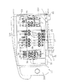
図2に示すように、旋回基板26上には、メーンの補強体としての左右一対の縦リブ29L,29Rが前部から後部にわたって配置されて溶接等によって固定されていると共に、その他の補強部材及び各種機器を取り付けるためのブラケット、ステー等が溶接によって固定されこれらによって旋回フレームが構成されている。
The rear upper surface and the right upper surface of the swivel base 12 are open, and these open portions protrude upward from the top surface of the swivel base 12 and are covered with a rounded bonnet 42.
A seat (driver's seat) 30 is arranged on the left side of the swivel base 12 in the left-right direction, and the seat 30 is covered with the cabin 14.
As shown in FIG. 2, a pair of left and right vertical ribs 29 </ b> L and 29 </ b> R as main body reinforcements are disposed on the swivel board 26 from the front to the rear and fixed by welding or the like, and other reinforcing members In addition, brackets, stays, and the like for attaching various devices are fixed by welding, and a turning frame is configured by these.

左右の縦リブ29L,29Rの前端側は上下方向に高く形成され、左右の縦リブ29L,29Rの後部側は上下方向に低く形成され、左右の縦リブ29L,29Rのうちキャビン14側(左側)の縦リブ29Lの前端部は、キャビン14よりも左右方向内方に配置され、キャビン14側(左側)の縦リブ29Lの後部側は、左右方向外方に傾斜されて、キャビン14の下方に配置されている。
旋回基板26の前後方向中途部上に左右方向に配置された仕切板41が設けられ、前記キャビン14側(左側)の縦リブ29Lは、その後端が仕切板41に接当又は近接され、キャビン14とは逆側(右側)の縦リブ29Rは、その後端部が仕切板41の端部外方を通って仕切板41よりも後方に突出した後に左右方向外方に屈曲突出されて、仕切板41に連続する仕切部43を構成している。前記スイングシリンダ21の前端部はスイングブラケット17に連結され、スイングシリンダ21の後端部は仕切板41よりも後方に突出されて、右側の縦リブ29Rの仕切部43等に連結されている。
The front end sides of the left and right vertical ribs 29L, 29R are formed high in the vertical direction, the rear side of the left and right vertical ribs 29L, 29R is formed low in the vertical direction, and the cabin 14 side (left side) of the left and right vertical ribs 29L, 29R. ) Of the vertical rib 29L is disposed inward in the left-right direction with respect to the cabin 14, and the rear side of the vertical rib 29L on the cabin 14 side (left side) is inclined outward in the left-right direction. Is arranged.
A partition plate 41 arranged in the left-right direction is provided on a midway portion in the front-rear direction of the swivel board 26, and the rear end of the vertical rib 29L on the cabin 14 side (left side) is brought into contact with or close to the partition plate 41, so that the cabin 14, the vertical rib 29R on the opposite side (right side) has a rear end portion that protrudes rearward from the partition plate 41 through the end portion of the partition plate 41 and then bends and protrudes outward in the left-right direction. A partition 43 that is continuous with the plate 41 is formed. The front end portion of the swing cylinder 21 is connected to the swing bracket 17, and the rear end portion of the swing cylinder 21 protrudes rearward from the partition plate 41 and is connected to the partition portion 43 of the right vertical rib 29R.

支持ブラケット16は、左右の縦リブ29L,29Rの前端部間に溶接等によって固定されていて、旋回台12の前面から前方に突出している。
従って、左右の縦リブ29L,29Rの前端側は上下方向に高く形成されているため、支持ブラケット16、スイングブラケット17乃至作業装置13の重量に耐え得るように、左右の縦リブ29L,29Rの前端側の強度を高めることができる。しかも、キャビン14側(左側)の縦リブ29Lの後部側は、左右方向外方に傾斜されて、キャビン14の下方に配置されているので、縦リブ29Lによって、キャビン14の下方部分の旋回基板26の強度を効果的に向上させることもでき、旋回基板14全体を左右の縦リブ29L,29Rによってうまく補強することができる。また、キャビン14側(左側)の縦リブ29Lの前端部は、キャビン14よりも左右方向内方に配置され、キャビン14側(左側)の縦リブ29Lの後部側は、左右方向外方に傾斜されて、キャビン14の下方に配置されているので、左右の縦リブ29L,29Rがあるにも拘わらず、キャビン14の底板67を極力低く位置に設定することができ、このため、キャビン14の天井部を低い位置に設定しても、キャビン14内の上下空間を大きくとることができるようになる。
The support bracket 16 is fixed between the front ends of the left and right vertical ribs 29L and 29R by welding or the like, and protrudes forward from the front surface of the swivel base 12.
Accordingly, the front end sides of the left and right vertical ribs 29L and 29R are formed high in the vertical direction, so that the left and right vertical ribs 29L and 29R can withstand the weight of the support bracket 16, the swing bracket 17 and the work device 13. The strength on the front end side can be increased. Moreover, since the rear side of the vertical rib 29L on the cabin 14 side (left side) is inclined outward in the left-right direction and is disposed below the cabin 14, the swivel board in the lower portion of the cabin 14 is arranged by the vertical rib 29L. 26 can be effectively improved, and the entire revolving substrate 14 can be well reinforced by the left and right vertical ribs 29L and 29R. Further, the front end portion of the vertical rib 29L on the cabin 14 side (left side) is disposed inward in the left-right direction with respect to the cabin 14, and the rear side of the vertical rib 29L on the cabin 14 side (left side) is inclined outward in the left-right direction. Since the left and right vertical ribs 29L and 29R are provided, the bottom plate 67 of the cabin 14 can be set to a position as low as possible. Even if the ceiling portion is set at a low position, the vertical space in the cabin 14 can be increased.

旋回基板26上の後部には、エンジン37が配置され、エンジン37の左右一側部(左右方向右側)には、ラジエータ40、エンジン37の左右他側部(左右方向左側)には油圧ポンプ39がそれぞれ配置されている。
また、旋回基板26上の左右方向一側部(図例では右側)の前側には、燃料タンク33、制御弁31がそれぞれ配置され、制御弁31及び燃料タンク33の後側には、作動油タンク35が配置されている。
そして、これら燃料タンク33、制御弁31、油圧ポンプ39、エンジン37、ラジエータ40は、ボンネット42で覆われている。
An engine 37 is disposed on the rear portion of the swivel board 26. A radiator 40 is disposed on one side of the engine 37 (right side in the left-right direction), and a hydraulic pump 39 is disposed on the left and right other side (left side in the left-right direction) of the engine 37. Are arranged respectively.
Further, a fuel tank 33 and a control valve 31 are respectively arranged on the front side of one side portion in the left-right direction (right side in the illustrated example) on the swivel board 26, and hydraulic oil is disposed on the rear side of the control valve 31 and the fuel tank 33. A tank 35 is arranged.
The fuel tank 33, the control valve 31, the hydraulic pump 39, the engine 37, and the radiator 40 are covered with a bonnet 42.

バッテリー48が制御弁31の左右方向内方に設けられ、該バッテリー48は、旋回基板26の上方に左右の縦リブ29L,29Rよりも高い位置に配置され、バッテリー48の下方に、制御弁31のバルブBと各種油圧機器とを接続する後述の油圧ホース57が配置されている。
このボンネット42は、エンジン37、油圧ポンプ39、ラジエータ40、作動油タンク35の後部を覆う後部ボンネット42Aと、燃料タンク33、制御弁31、作動油タンク35の前部等を覆う側部ボンネット42Bとに分離形成されており、後部ボンネット42Aは旋回基板26上の後部に設けられ、側部ボンネット42Bは旋回基板26上の右側部に設けられている。また、例えば、側部ボンネット42Bの前側は前後方向に回動自在に枢支されて、この側部ボンネット42Bを開放することによって、燃料タンク33、制御弁31、作動油タンク35がメンテナンスできるようになっている。
A battery 48 is provided inward of the control valve 31 in the left-right direction. The battery 48 is disposed above the swivel board 26 at a position higher than the left and right vertical ribs 29L, 29R, and below the battery 48, the control valve 31. A hydraulic hose 57, which will be described later, is connected to connect the valve B to the various hydraulic devices.
The bonnet 42 includes a rear bonnet 42A that covers the rear part of the engine 37, the hydraulic pump 39, the radiator 40, and the hydraulic oil tank 35, and a side bonnet 42B that covers the fuel tank 33, the control valve 31, the front part of the hydraulic oil tank 35, and the like. The rear bonnet 42 </ b> A is provided at the rear part on the turning substrate 26, and the side bonnet 42 </ b> B is provided at the right side on the turning substrate 26. Further, for example, the front side of the side bonnet 42B is pivotally supported in the front-rear direction so that the fuel tank 33, the control valve 31, and the hydraulic oil tank 35 can be maintained by opening the side bonnet 42B. It has become.

図3、図7に示すように、旋回台12にエンジン37等を跨ぐように支持フレーム61が設けられている。この支持フレーム61は後脚部と、左右一対の前脚部と、これら脚部の上端に連結されると共に後部ボンネット42Aが取り付けられる上板62とから主構成されていて、各後脚部及び前脚部の下端が旋回基板26等に取付固定されている。
なお、側部ボンネット42Bは着脱自在に旋回台12に取り付けられていてよいし、側部ボンネット42Bの後部を前後方向に回動できるように枢支されてもよい。
前記キャビン14は旋回基板26の左側に搭載され、キャビン14の後端部が後部ボンネット42A上に載るようになっている。即ち、キャビン14の後端部に、後部ボンネット42A上に載るように下側から上側に向けて凹んだ載置凹部65が設けられている。
As shown in FIGS. 3 and 7, a support frame 61 is provided on the swivel base 12 so as to straddle the engine 37 and the like. The support frame 61 mainly includes a rear leg portion, a pair of left and right front leg portions, and an upper plate 62 connected to the upper ends of the leg portions and to which the rear bonnet 42A is attached. The lower end of the part is fixedly attached to the turning substrate 26 and the like.
The side bonnet 42B may be detachably attached to the swivel base 12, or may be pivotally supported so that the rear part of the side bonnet 42B can be rotated in the front-rear direction.
The cabin 14 is mounted on the left side of the revolving board 26 so that the rear end portion of the cabin 14 is placed on the rear bonnet 42A. That is, a mounting recess 65 that is recessed from the lower side toward the upper side so as to be placed on the rear bonnet 42A is provided at the rear end portion of the cabin 14.

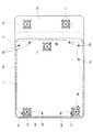
図8及び図9に示すように、キャビン14は、下端が開口した箱状に形成されて、キャビン14下端の後部ボンネット42A前方に下端開口66が設けられ、キャビン14の下端開口66を塞ぐように、ステップ(底板)67がキャビン14の下端開口縁部にボルト等の締結具69により着脱自在に取り付けられている。
図7に示すように、旋回基板26の前部に、左右一対のキャビン支持体71が上方突設され、これらキャビン支持体71に、ステップ67の前端部の左右2箇所が、それぞれ防振部材72を介して支持され、ステップ67の前端部は旋回基板26から浮いた状態に保持されている。また、旋回基板26の後部に、1つのキャビン支持体73が上方突出され、このキャビン支持体73に、ステップ67の後端部の1箇所が、防振部材74を介して支持されている。また、後部ボンネット42Aの支持フレーム61の上板62に、防振部材75を介してキャビン14の載置凹部65が支持されている。
As shown in FIGS. 8 and 9, the cabin 14 is formed in a box shape having an open lower end, and a lower end opening 66 is provided in front of the rear bonnet 42 </ b> A of the lower end of the cabin 14 so as to close the lower end opening 66 of the cabin 14. Further, a step (bottom plate) 67 is detachably attached to a lower end opening edge of the cabin 14 by a fastener 69 such as a bolt.
As shown in FIG. 7, a pair of left and right cabin supports 71 project upward from the front portion of the swivel board 26, and the left and right two locations of the front end portion of the step 67 are respectively provided on the cabin support bodies 71. The front end portion of step 67 is held in a state of being lifted from the turning substrate 26. In addition, one cabin support 73 projects upward from the rear portion of the swivel board 26, and one location at the rear end of the step 67 is supported by the cabin support 73 via a vibration isolation member 74. In addition, the mounting recess 65 of the cabin 14 is supported on the upper plate 62 of the support frame 61 of the rear bonnet 42 </ b> A via a vibration isolation member 75.

旋回基板26上の旋回軸心X位置にはスイベルジョイント32が配設され、その近傍に旋回台12を旋回させる旋回モータ34が配設されている。
制御弁31は、作業装置13のスイングブラケット17、ブーム18、アーム19、バケット20を駆動させるスイングシリンダ21、ブームシリンダ22、アームシリンダ23、バケットシリンダ24を制御したり、走行装置2の左右一対の走行装置用モータM、旋回モータ34等の油圧機器を制御するものであり、図4に示すように、複数個のバルブBを一方向に配列したものである。そして、1つのバルブBで1つの油圧機器が制御できるようになっている。
A swivel joint 32 is provided at the position of the turning axis X on the turning substrate 26, and a turning motor 34 for turning the turntable 12 is provided in the vicinity thereof.
The control valve 31 controls the swing bracket 21, the boom 18, the arm 19, and the bucket 20 of the work device 13, controls the swing cylinder 21, the boom cylinder 22, the arm cylinder 23, and the bucket cylinder 24. As shown in FIG. 4, a plurality of valves B are arranged in one direction. One valve B can control one hydraulic device.

図3、4に示すように、この制御弁31を構成する各バルブB(B1〜B11)は、直動スプール型切換バルブから構成され、それぞれスプールの操作方向(移動方向)に直交する方向に配列されて連結され、一体化されている。
図4、5に示すように、このような制御弁31は、各バルブBの配列方向が前後方向に一致するように、且つ夫々のバルブBに形成された、圧油の供給・戻りポート、油圧ポンプ39から圧油を流入するポンプポート、作動油タンク35へと圧油を流出するタンクポート等の各ポートPのポート形成面36が左右方向内側に向けて傾斜状になるように、燃料タンク33の上側に配置されている。
As shown in FIGS. 3 and 4, each valve B (B1 to B11) constituting the control valve 31 is constituted by a direct acting spool type switching valve in a direction perpendicular to the operation direction (moving direction) of the spool. Arranged, connected and integrated.
As shown in FIGS. 4 and 5, such a control valve 31 includes a pressure oil supply / return port formed in each valve B so that the arrangement direction of the valves B coincides with the front-rear direction. Fuel so that the port forming surface 36 of each port P such as a pump port for flowing pressure oil from the hydraulic pump 39 and a tank port for flowing pressure oil to the hydraulic oil tank 35 is inclined inward in the left-right direction. It is arranged on the upper side of the tank 33.

即ち、制御弁31は、バルブBの配列方向が前後方向になると共に、バルブBのポート形成面36が左右方向内側に向くように、左右方向内側から外側に向かうに従って上方に移行する傾斜状に配置されている。
図4〜6に示すように、燃料タンク33は、左右一対の縦リブ29L,29Rの一方(右側)の左右方向外側に位置しており前後に長く左右に広幅に形成され、その上面が上下に傾斜する傾斜部33aと、この傾斜部33aよりも幅狭に形成されて傾斜部33aから下側に膨出する下膨出部33bと、傾斜部33の前側で上方に膨出する上膨出部33cとを有している。
That is, the control valve 31 is inclined so that the arrangement direction of the valves B is the front-rear direction and the port forming surface 36 of the valve B is directed inward in the left-right direction so as to move upward from the inner side in the left-right direction. Has been placed.
4-6, the fuel tank 33 is located in the left-right direction outer side of one (right side) of the pair of left and right vertical ribs 29L, 29R, and is formed long and wide in the front and back, and its upper surface is vertically An inclined portion 33a which is inclined to the upper side, a lower bulging portion 33b which is formed narrower than the inclined portion 33a and bulges downward from the inclined portion 33a, and an upper bulge which bulges upward on the front side of the inclined portion 33 And a protruding portion 33c.

燃料タンク33の傾斜部33aの上面は、左右方向外側から左右方向内側(中央側)に行くにしたがってその上下幅が小さくなるように傾斜している。
制御弁31と燃料タンク33との間には、制御弁31を支持する支持体50が設けられており、この支持体50は、制御弁31を取り付ける取付台51と、取付台51の左右方向内側を旋回基板26に取り付ける旋回基板用固定ブラケット52、取付台51の左右方向外側を作動油タンク35に取り付ける作動油タンク用固定ブラケット53とを有している。
The upper surface of the inclined portion 33a of the fuel tank 33 is inclined so that its vertical width decreases from the outer side in the left-right direction toward the inner side (center side) in the left-right direction.
A support body 50 that supports the control valve 31 is provided between the control valve 31 and the fuel tank 33, and the support body 50 has a mounting base 51 to which the control valve 31 is attached and a left-right direction of the mounting base 51. A turning board fixing bracket 52 for attaching the inner side to the turning board 26 and a hydraulic oil tank fixing bracket 53 for attaching the outer side of the mounting base 51 to the hydraulic oil tank 35 are provided.

この取付台51は、燃料タンク33の傾斜部33aの上面に沿って設けられ、例えば平面視で矩形状に形成されて、取付台51の上面に設けた載置部54に制御弁31を取付可能となっている。
この載置部54は、取付台51の上面が左右方向に内側に向いて傾斜する傾斜部分51Aに設けられ、この載置部54に、バルブBのポート形成面36が左右方向内側に向くように制御弁31は取り付けられている。
従って、旋回基板26上であってキャビン14とは逆側(右側)の縦リブ29Rの左右方向外方に、燃料タンク33と、油圧機器を制御する複数のバルブBを有する制御弁31が設けられ、燃料タンク33の上方に制御弁31が配置されている。燃料タンク33の前後方向一端部(図例では前端部)は、制御弁31よりも前後方向に突出すると共に、上方に突出され、その上端部に上方突出した給油口77が設けられている。
The mounting base 51 is provided along the upper surface of the inclined portion 33a of the fuel tank 33. For example, the mounting base 51 is formed in a rectangular shape in plan view, and the control valve 31 is attached to the mounting portion 54 provided on the upper surface of the mounting base 51. It is possible.
The mounting portion 54 is provided on an inclined portion 51A in which the upper surface of the mounting base 51 is inclined inward in the left-right direction, and the port forming surface 36 of the valve B is directed inward in the left-right direction on the mounting portion 54. A control valve 31 is attached.
Therefore, a control valve 31 having a fuel tank 33 and a plurality of valves B for controlling hydraulic equipment is provided on the swivel board 26 and on the outer side of the vertical rib 29R on the opposite side (right side) of the cabin 14 in the left-right direction. The control valve 31 is disposed above the fuel tank 33. One end of the fuel tank 33 in the front-rear direction (front end in the illustrated example) protrudes in the front-rear direction from the control valve 31, protrudes upward, and is provided with a fuel supply port 77 protruding upward at the upper end.

なお、載置部54を設けずに、制御弁31を取付台51の傾斜部分51aに直接取り付けるようにしてもよい。
取付台51の左右方向両端部側には、旋回基板26の上面と略平行な一対の取付部51L,51Rが形成されており、旋回基板26から起立した旋回基板用固定ブラケット52に、取付台51の左右方向一方(内側)の取付部55Lが取り付けられて、取付台51の左右方向内側は旋回基板26に固定されている。
旋回基板用固定ブラケット52は側面視で略L形のブラケットであり、旋回基板用固定ブラケット52の前側端部は、左右方向外側の支持ブラケット16の後部に固定されている。
The control valve 31 may be directly attached to the inclined portion 51 a of the mounting base 51 without providing the mounting portion 54.
A pair of mounting portions 51L and 51R that are substantially parallel to the upper surface of the swivel board 26 are formed on both ends in the left-right direction of the mount 51. The mount base 51 is fixed to the swivel board fixing bracket 52 that stands up from the swivel board 26. One mounting portion 55 </ b> L in the left-right direction (inner side) 51 is attached, and the inner side in the left-right direction of the mounting base 51 is fixed to the turning substrate 26.
The turning board fixing bracket 52 is a substantially L-shaped bracket in a side view, and the front end of the turning board fixing bracket 52 is fixed to the rear portion of the support bracket 16 on the outer side in the left-right direction.

取付台51の左右方向他方(外側)の取付部51Rには、作動油タンク用固定ブラケット53が取り付けられ、この作動油タンク用固定ブラケット53は、後方上方に延びて取付台51よりも上方で作動油タンク35の前側に固定されており、これによって、取付台51の左右方向外側は吊り状に固定されている。
したがって、燃料タンク33の左右方向外側は、開放状態となり、これによって、燃料タンク33は、左右方向外方へ取り出しできるようになっている。
即ち、制御弁31と燃料タンク33との間に平板状の取付台51を設け、燃料タンク33の一側面側(左右方向内側)に位置する取付台51の一側部を旋回基板26に固定し、燃料タンク33の他側面側(左右方向外側)に位置する取付台51の他側部を吊り状に固定することで、燃料タンク33の他側面側を開放状態にし、燃料タンク33を外方へ引き出し可能にしている。
A hydraulic oil tank fixing bracket 53 is attached to the mounting portion 51R on the other side (outer side) of the mounting base 51 in the left-right direction. The hydraulic oil tank fixing bracket 53 extends rearward and upward above the mounting base 51. It is being fixed to the front side of the hydraulic oil tank 35, and, thereby, the left-right direction outer side of the mounting base 51 is being fixed to the suspension shape.
Therefore, the outer side in the left-right direction of the fuel tank 33 is in an open state, so that the fuel tank 33 can be taken out outward in the left-right direction.
That is, a flat mounting base 51 is provided between the control valve 31 and the fuel tank 33, and one side portion of the mounting base 51 located on one side surface (inward in the left-right direction) of the fuel tank 33 is fixed to the turning substrate 26. Then, by fixing the other side of the mounting base 51 located on the other side of the fuel tank 33 (outside in the left-right direction) in a suspended manner, the other side of the fuel tank 33 is opened, and the fuel tank 33 is removed. It is possible to pull it out.

燃料タンク33の上方に制御弁31を配置したことで、旋回台12上の上下スペースを有効に活用でき、しかも、燃料タンク33を引き出し可能としたことで、ボンネット42Bやカバー28を取り外したり、開放すれば旋回台12から燃料タンク12を交換したりメンテナンスをすることができる。
次に、制御弁31の各バルブBを前側から順に説明すると、図4に示すように、B1は、旋回台12を旋回させる旋回モータ34を制御する旋回用バルブで、B2は、ドーザ9を揺動させる油圧シリンダを制御するドーザ用バルブで、B3は、油圧ポンプ39の圧油を、各バルブBに供給する状態と、各バルブBに供給せずに作動油タンク35に戻す状態とに切り換える切換弁バルブ、これら、各バルブB1〜B3はそれぞれ個別にケースに収められて前後方向に連結されている。
By arranging the control valve 31 above the fuel tank 33, the upper and lower spaces on the swivel base 12 can be used effectively, and by allowing the fuel tank 33 to be pulled out, the hood 42B and the cover 28 can be removed, If it opens, the fuel tank 12 can be replaced | exchanged from the swivel stand 12, and maintenance can be performed.
Next, each valve B of the control valve 31 will be described in order from the front side. As shown in FIG. 4, B <b> 1 is a turning valve that controls the turning motor 34 that turns the turntable 12, and B <b> 2 is the dozer 9. B3 is a dozer valve that controls the hydraulic cylinder to be swung. B3 is a state in which the pressure oil of the hydraulic pump 39 is supplied to each valve B and a state in which the hydraulic oil is not supplied to each valve B but returned to the hydraulic oil tank 35. The switching valve valve to be switched, these valves B1 to B3 are individually housed in a case and connected in the front-rear direction.

B4は、バケット20の代わりに装着される油圧アタッチメントを制御するSP(スペシャルポート)用バルブで、B5は、スイングシリンダ21を制御するスイング用バルブで、B6は、バケットシリンダ24を制御するバケット用バルブで、B7は、ブームシリンダ22を制御するブーム用バルブで、B8は、アームシリンダ23を制御するアーム用バルブで、これら、各バルブB4〜8は前後方向に配列されて1つのケースに収められている。
B9及びB11は、走行装置2の走行用モータMを制御する走行用バルブで、B10は、走行用バルブに圧油を供給するする優先切換バルブで、これら、各バルブB9〜11はそれぞれ個別にケースに収まられて前後方向に連結されている。
B4 is a SP (special port) valve that controls a hydraulic attachment mounted instead of the bucket 20, B5 is a swing valve that controls the swing cylinder 21, and B6 is a bucket that controls the bucket cylinder 24. B7 is a boom valve that controls the boom cylinder 22, and B8 is an arm valve that controls the arm cylinder 23. These valves B4 to B8 are arranged in the front-rear direction and housed in one case. It has been.
B9 and B11 are travel valves that control the travel motor M of the travel device 2, and B10 is a priority switching valve that supplies pressure oil to the travel valves. These valves B9 to B11 are individually provided. It is housed in a case and connected in the front-rear direction.

そして、バケット用バルブB6、ブーム用バルブB7、アーム用バルブB8、旋回用バルブB1及び切換バルブB3は、図2、5、7に示すように、シート30の左右両側に設けられた左右の操作レバー44L,44Rの操作によってパイロット圧により切換え操作される。
走行用バルブB9、B11、SP用バルブB4、ドーザ用バルブB2及びスイング用バルブB5は、図2、5、7に示すように、それぞれ走行操作レバー45L,45R又は走行操作ペダル49L,49R、SP操作ペダル46、ドーザ操作レバー、スイング操作ペダル47によって操作される。
The bucket valve B6, the boom valve B7, the arm valve B8, the turning valve B1 and the switching valve B3 are operated on the left and right sides of the seat 30 as shown in FIGS. Switching is performed by pilot pressure by operating the levers 44L and 44R.
The travel valves B9 and B11, the SP valve B4, the dozer valve B2 and the swing valve B5 are respectively provided with travel operation levers 45L and 45R or travel operation pedals 49L and 49R and SP, as shown in FIGS. The operation pedal 46, the dozer operation lever, and the swing operation pedal 47 are operated.

操作レバー44L,44R、走行操作レバー45L、45R、走行操作ペダル49L,49R、SP操作ペダル46、スイング操作ペダル47等は、例えば、左右一対のリブの挿通孔38を介して対応する各バルブBのスプールに油圧ホースにより連動連結され、ドーザ操作レバーはシート30の近傍に設けられていてドーザ用バルブB2のスプールに連動連結されている。
バルブB4〜B8の作動油を供給・排出するためのポートPには、L形90°継手56を介して油圧ホース57が接続されるようになっている。即ち、油圧バルブB4〜B8に接続された各油圧ホース57は、継手56によって左右方向内側に向けられて、右側の縦リブ29L,29Rの上端部を越えて旋回台12内(カバー28の上端よりも下側)に入るように配管され、上下の支持ブラケット16の間を通って、作業装置13のスイングブラケット17、ブーム18、アーム19、バケット20を駆動させる各油圧機器に接続される。
The operation levers 44L and 44R, the travel operation levers 45L and 45R, the travel operation pedals 49L and 49R, the SP operation pedal 46, the swing operation pedal 47, and the like, for example, correspond to each valve B via the pair of right and left rib insertion holes 38. The spool is linked to the spool by a hydraulic hose, and the dozer operation lever is provided in the vicinity of the seat 30 and linked to the spool of the dozer valve B2.
A hydraulic hose 57 is connected to a port P for supplying and discharging the hydraulic oil of the valves B4 to B8 via an L-shaped 90 ° joint 56. That is, each hydraulic hose 57 connected to the hydraulic valves B4 to B8 is directed inward in the left-right direction by the joint 56, and passes through the upper ends of the right vertical ribs 29L and 29R in the swivel 12 (the upper end of the cover 28). And is connected to each hydraulic device that drives the swing bracket 17, the boom 18, the arm 19, and the bucket 20 of the work device 13 through the space between the upper and lower support brackets 16.

このとき、制御弁31のポート形成面36が左右方向内側に傾斜しているので、各B4〜B8の油圧ホース57を強制的に下方に曲げなくても、油圧ホース57は左右方向内側にいくに従って下方に移行するようになり、これにより、油圧ホース57の配管が行いやすく、スムーズに油圧ホース57の配管を行うことができる。
しかも、B4〜B8の供給・排出のポート形成面36が縦リブ29L,29Rよりも高く設定しているので、油圧ホース57は強制的に曲げなくても直線的に配管することで縦リブ29L,29Rを越えて旋回台12内へ通すことができ、この点からも油圧ホース57の配管が行いやすい。
At this time, since the port forming surface 36 of the control valve 31 is inclined inward in the left-right direction, the hydraulic hose 57 goes inward in the left-right direction without forcibly bending the B4-B8 hydraulic hoses 57 downward. Accordingly, the hydraulic hose 57 can be easily piped, and the hydraulic hose 57 can be smoothly piped.
In addition, since the port forming surface 36 for supplying and discharging B4 to B8 is set higher than the vertical ribs 29L and 29R, the hydraulic hose 57 can be straightly piped without being forced to bend. , 29R can be passed into the swivel 12 and the hydraulic hose 57 can be easily piped from this point.

また、バルブB1、B2、B9、B11の各ポートPに接続された油圧ホース57は、バルブB1、B2、B9、B11の各ポートPから斜め上方に立ち上がった後、左右方向内側に向けられて、主にスイベルジョイント32に接続される。また、バルブB3の各ポートPに接続された油圧ホース57は、バルブB3の各ポートPから上方に立ち上がった後、作動油タンク35、油圧ポンプ39に接続されている。
このとき、制御弁31の前後略中央に、作業装置13用のバルブB4〜8が集中配置され、その両側に走行装置2用のバルブB9〜11や旋回台12及びドーザ9等のその他のバルブB1〜3が集中配置され、且つ、作業装置13用のバルブB4〜8を制御弁31から下方へ配管し、走行装置2用及びその他のバルブB9〜11、B1〜3を制御弁31から上方に立ち上げているので、複数の油圧ホース57がどの装置に対応しているか容易に認識でき、制御弁31のメンテナンスが行い易い。
In addition, the hydraulic hose 57 connected to each port P of the valves B1, B2, B9, and B11 rises obliquely upward from each port P of the valves B1, B2, B9, and B11, and then faces inward in the left-right direction. , Mainly connected to the swivel joint 32. The hydraulic hose 57 connected to each port P of the valve B3 rises upward from each port P of the valve B3 and is then connected to the hydraulic oil tank 35 and the hydraulic pump 39.
At this time, the valves B4 to 8 for the working device 13 are centrally arranged at the front and rear of the control valve 31, and other valves such as the valves B9 to 11 for the traveling device 2 and the swivel 12 and the dozer 9 are arranged on both sides thereof. B1 to B3 are centrally arranged, and valves B4 to B8 for the working device 13 are piped downward from the control valve 31, and the traveling device 2 and other valves B9 to B11 and B1 to B3 are moved upward from the control valve 31. Therefore, it is easy to recognize which device the plurality of hydraulic hoses 57 corresponds to, and the control valve 31 can be easily maintained.

また、各バルブBに油圧ホース57を接続する際にも、油圧ホース57の配管の経路を上下に分けているので、油圧ホース57の配管が行い易い。さらに、バルブBのポート形成面36上がフルオープンに開放されているので、各種油圧ホース57の接続が行い易い。
図10〜図12に示すように、ステップ67の前端部、ステップ67の後端部及びキャビン14の載置凹部65の防振部材72,74,75は、ゴム等により形成した弾性体(エンジンマウントゴム)81と、金属板等により形成した固定板82と、金属パイプ等により形成した円筒状の筒体83とを備え、弾性体81は固定板82及び筒体83に対して焼き付け等より一体とされている。
In addition, when connecting the hydraulic hose 57 to each valve B, the piping of the hydraulic hose 57 is divided up and down, so that the piping of the hydraulic hose 57 is easy to perform. Furthermore, since the port forming surface 36 of the valve B is fully open, various hydraulic hoses 57 can be easily connected.
As shown in FIGS. 10 to 12, the front end portion of Step 67, the rear end portion of Step 67, and the vibration isolation members 72, 74, 75 of the mounting recess 65 of the cabin 14 are elastic bodies (engines) formed of rubber or the like. Mount rubber) 81, a fixing plate 82 formed of a metal plate or the like, and a cylindrical tube 83 formed of a metal pipe or the like. The elastic body 81 is baked on the fixing plate 82 and the tube 83 or the like. It is united.

弾性体81の中央部には円形の取付孔80が形成され、この取付孔80を介して筒体83が弾性体81の中央部に上下方向に貫通保持されている。固定板82の内端側には、下方に向けて円筒状に折曲した筒状部85が形成され、弾性体81に、固定板82の筒状部85が埋設されている。固定板82の外周部が、ボルト等の締結具84によってキャビン支持体71,73又は上板62に締付固定されている。
ステップ67又はキャビン14の載置凹部65の下面側に防振部材72,74,75を配置して、防振部材72,74,75の筒体83にボルト86を挿通すると共に、ステップ67の取付孔にボルト86を挿通して、ナット89を締め付けることにより、防振部材72,74,75がボルト86及びナット89によりステップ67又は載置凹部65の下面側に装着されている。ボルト86の頭部と筒体83との間には座金90が設けられている。弾性体81の上側にカップ87が設けられ、カップ87とステップ67又は載置凹部65との間にスペーサ88が介在されている。
A circular mounting hole 80 is formed in the central portion of the elastic body 81, and the cylinder 83 is vertically held through and held in the central portion of the elastic body 81 through the mounting hole 80. On the inner end side of the fixed plate 82, a cylindrical portion 85 that is bent downward in a cylindrical shape is formed, and the cylindrical portion 85 of the fixed plate 82 is embedded in the elastic body 81. The outer peripheral portion of the fixing plate 82 is fastened and fixed to the cabin supports 71 and 73 or the upper plate 62 by a fastener 84 such as a bolt.
The vibration isolating members 72, 74, and 75 are disposed on the lower surface side of the mounting recess 65 of the step 67 or the cabin 14, and the bolts 86 are inserted into the cylinders 83 of the vibration isolating members 72, 74, and 75. By inserting the bolt 86 into the mounting hole and tightening the nut 89, the vibration isolating members 72, 74, and 75 are attached to the lower surface side of the step 67 or the mounting recess 65 by the bolt 86 and the nut 89. A washer 90 is provided between the head of the bolt 86 and the cylinder 83. A cup 87 is provided above the elastic body 81, and a spacer 88 is interposed between the cup 87 and the step 67 or the mounting recess 65.

従って、底板67の前端部と後端部とが防振部材72,74を介して旋回基板26に支持され、キャビン14の後端部がボンネット42Aに防振部材75を介して支持されているので、メンテナンス等のために、キャビン14をステップ67から取り外しても、ステップ67の前端部及び後端部が防振部材72,74を介して、旋回基板26に支持されているため、ステップ67が後下がりに傾斜せずに済み、メンテナンス等をスムーズになすことができる。
図13〜図15に示すように、ステップ67上に、前記シート30を支持するシート台91が取り付けられ、シート台91とステップ67との間にエアコン本体92が設置され、エアコン本体92の側方に、エアコン本体92に内外気を導入する内外気導入部93が設けられている。
Accordingly, the front end portion and the rear end portion of the bottom plate 67 are supported by the turning substrate 26 via the vibration isolating members 72 and 74, and the rear end portion of the cabin 14 is supported by the hood 42A via the vibration isolating member 75. Therefore, even if the cabin 14 is removed from the step 67 for maintenance or the like, the front end portion and the rear end portion of the step 67 are supported on the turning substrate 26 via the vibration isolating members 72 and 74. However, it is not necessary to incline toward the rear, and maintenance and the like can be performed smoothly.
As shown in FIGS. 13 to 15, a seat base 91 that supports the seat 30 is mounted on the step 67, and an air conditioner main body 92 is installed between the seat base 91 and the step 67. On the other hand, an inside / outside air introduction section 93 for introducing inside / outside air into the air conditioner main body 92 is provided.

内外気導入部93に、切換操作体94が上下移動自在に保持され、内外気導入部93の側壁95に内気導入窓96が設けられ、ステップ67に外気導入窓97が設けられている。切換操作体94に、内気導入窓96に遮断自在に連通する内気導入口98が設けられ、ステップ67の外気導入窓97を開閉自在に塞ぐカバー体99が支持軸100廻りに回動自在に支持され、カバー体99に、カバー体99に連動して支持軸100廻りに回動する連動体101が突設されている。ステップ67の下面側に、外気導入窓97に対応して下方に突出した外気取入部105が設けられ、外気取入部105の底壁に外気取入口106が設けられると共に、外気取入口106を塞ぐようにフィルター107が設けられている。   The switching operation body 94 is held by the inside / outside air introduction portion 93 so as to be movable up and down, an inside air introduction window 96 is provided on the side wall 95 of the inside / outside air introduction portion 93, and an outside air introduction window 97 is provided at step 67. The switching operation body 94 is provided with an inside air introduction port 98 that communicates with the inside air introduction window 96 so as to be shut off, and a cover body 99 that covers the outside air introduction window 97 in step 67 so as to be openable and closable is rotatably supported around the support shaft 100. The cover body 99 is provided with an interlocking body 101 that rotates about the support shaft 100 in conjunction with the cover body 99. An outside air intake portion 105 that protrudes downward corresponding to the outside air introduction window 97 is provided on the lower surface side of step 67, and an outside air inlet 106 is provided on the bottom wall of the outside air inlet portion 105 and the outside air inlet 106 is closed. A filter 107 is provided.

そして、図13及び図14に示すように、前記切換操作体94を上方移動させたとき、カバー体99及び連動体101がステップ67上で水平状態になって、外気導入窓97を塞ぐと共に、切換操作体94の内気導入口98が内気導入窓96に連通して、図14に矢印で示すように内気を内気導入窓96及び内気導入口98を通してエアコン本体92に導入するようになっている。また、図15に示すように、切換操作体94を下方移動させたとき、連動体101が切換操作体94により下方に押圧されて、カバー体99及び連動体101が支持軸100廻りに回動して、外気導入窓97が開放されると共に、切換操作体94の内気導入口98が内気導入窓96に対して下方にずれて内気導入窓96が切換操作体94により塞がれ、図15に矢印で示すように外気を外気取入口106及び外気導入窓97を通してエアコン本体92に導入するようになっている。   Then, as shown in FIGS. 13 and 14, when the switching operation body 94 is moved upward, the cover body 99 and the interlocking body 101 become horizontal on the step 67, block the outside air introduction window 97, and The inside air introduction port 98 of the switching operation body 94 communicates with the inside air introduction window 96, and the inside air is introduced into the air conditioner main body 92 through the inside air introduction window 96 and the inside air introduction port 98 as shown by arrows in FIG. . Further, as shown in FIG. 15, when the switching operation body 94 is moved downward, the interlocking body 101 is pressed downward by the switching operation body 94, and the cover body 99 and the interlocking body 101 rotate around the support shaft 100. Then, the outside air introduction window 97 is opened, the inside air introduction port 98 of the switching operation body 94 is shifted downward with respect to the inside air introduction window 96, and the inside air introduction window 96 is closed by the switching operation body 94, as shown in FIG. As shown by the arrows, the outside air is introduced into the air conditioner main body 92 through the outside air inlet 106 and the outside air introduction window 97.

図16〜図19に示すように、左右の走行操作ペダル49L,49Rは、支持脚111L,111Rとペダル板112L,112Rとゴム等で形成したカバー体113L,113Rとを備え、支持脚111L,111Rは、上方突出した脚部114と脚部114の下端から左右方向外方に屈曲した取付部115とを有し、取付部115に取付孔116が設けられている。
ペダル板112L,112Rは、前後方向中央部でくの字状に屈曲され、幅方向の左右外方側に、前後方向中央部に内嵌合孔118が設けられると共に、内嵌合孔118の前後方向両側に、一対の外嵌合孔119が設けられている。
As shown in FIGS. 16 to 19, the left and right traveling operation pedals 49L, 49R include support legs 111L, 111R, pedal plates 112L, 112R, and cover bodies 113L, 113R formed of rubber or the like, and support legs 111L, 111R has a leg part 114 protruding upward and an attachment part 115 bent outward in the left-right direction from the lower end of the leg part 114, and an attachment hole 116 is provided in the attachment part 115.
The pedal plates 112L and 112R are bent in a dogleg shape at the center portion in the front-rear direction, and an inner fitting hole 118 is provided in the center portion in the front-rear direction on the left and right outer sides in the width direction. A pair of outer fitting holes 119 are provided on both sides in the front-rear direction.

カバー体113L,113Rには、ペダル板112L,112Rの外周部に外嵌する環状の嵌合凸部121が下方突出され、ペダル板112L,112Rの内嵌合孔118及び外嵌合孔119に密着状に内嵌する内嵌合部122と外嵌合部123が、カバー体113L,113Rの下面側に突設されている。
従って、ペダル板112L,112Rに対してカバー体113L,113Rを上側から重合させて、嵌合凸部121をペダル板112L,112Rの外周部に外嵌させると共に、内嵌合部122及び外嵌合部123を内嵌合孔118及び外嵌合孔119に内嵌させることによって、カバー体113L,113Rがペダル板112L,112Rに対してずれないように、カバー体113L,113Rを接着剤を使用することなくペダル板112L,112Rに簡単に装着することができようになっている。
On the cover bodies 113L and 113R, annular fitting convex portions 121 that are fitted on the outer peripheral portions of the pedal plates 112L and 112R protrude downward, and are formed in the inner fitting holes 118 and the outer fitting holes 119 of the pedal plates 112L and 112R. An inner fitting portion 122 and an outer fitting portion 123 that fit in close contact with each other protrude from the lower surfaces of the cover bodies 113L and 113R.
Therefore, the cover bodies 113L and 113R are superposed on the pedal plates 112L and 112R from the upper side, and the fitting convex portion 121 is fitted on the outer peripheral portion of the pedal plates 112L and 112R, and the inner fitting portion 122 and the outer fitting are fitted. By fitting the joint portion 123 in the inner fitting hole 118 and the outer fitting hole 119, the cover bodies 113L and 113R are made of adhesive so that the cover bodies 113L and 113R are not displaced from the pedal plates 112L and 112R. The pedal plates 112L and 112R can be easily mounted without being used.

そして、左走行操作ペダル49Lのペダル板112Lと右走行操作ペダル49Rのペダル板112L,112Rとは、中央部で縦軸廻りに180度回転したとき互いに同一形状になるようになっており、左走行操作ペダル49Lのペダル板112Lと右走行操作ペダル49Rのペダル板112Rとは同一形状のものを、単に前後左右が逆になるように180度回転して使用することができるようになっている。また、左走行操作ペダル49Lのカバー体113Lと右走行操作ペダル49Rのカバー体113Rとは、中央部で縦軸廻りに180度回転したとき互いに同一形状になるようになっており、左走行操作ペダル49Lのカバー体113Lと右走行操作ペダル49Rのカバー体113Rとは同一形状のものを単に前後左右が逆になるように180度回転して使用することができるようになっている。従って、左右の走行操作ペダル49L,49Rのペダル板112L,112R及びカバー体113L,113Rを同一形状のもので兼用することができ、ペダル板112L,112R及びカバー体113L,113Rを安価かつ容易に製造することができる。   The pedal plate 112L of the left travel operation pedal 49L and the pedal plates 112L and 112R of the right travel operation pedal 49R are configured to have the same shape when rotated 180 degrees around the vertical axis at the center. The pedal plate 112L of the traveling operation pedal 49L and the pedal plate 112R of the right traveling operation pedal 49R can be used by rotating 180 degrees so that the front, rear, left and right are reversed. . Further, the cover body 113L of the left travel operation pedal 49L and the cover body 113R of the right travel operation pedal 49R have the same shape when rotated 180 degrees around the vertical axis at the center, and the left travel operation pedal The cover body 113L of the pedal 49L and the cover body 113R of the right travel operation pedal 49R can be used by rotating 180 degrees so that the front, back, left and right are reversed. Accordingly, the pedal plates 112L and 112R and the cover bodies 113L and 113R of the left and right traveling operation pedals 49L and 49R can be used in the same shape, and the pedal plates 112L and 112R and the cover bodies 113L and 113R can be inexpensively and easily used. Can be manufactured.

また、ペダル板112L,112Rの内嵌合孔118、外嵌合孔119が、支持脚111L,111Rの取付孔116に対応しており、このため、取付孔116を利用してビスやボルト等の締結具124で、支持脚111L,111Rを旋回台12側に取り付ける際に、工具を取付孔116に対応する嵌合孔118,119から挿入して該工具で締結具124を容易に回動操作等をすることができ、便利である。
キャビン14内のステップ67の前部上に、図20に示すゴムマット126が敷かれている。図20に示すように、ゴムマット126は、長方形状に形成されて、SP操作ペダル46用の挿通孔127と走行操作レバー45L,45R(走行操作ペダル49L,49R)用の挿通孔128とスイング操作ペダル47用の挿通孔129とが具備されている。このゴムマット126は、挿通孔127,128,129を通る左右方向の線分で前部マット131と後部マット132とに二分割されており、前部マット131の後端と後部マット132の前端とを接合することによって、長方形状のゴムマット126が構成されている。
Further, the inner fitting holes 118 and the outer fitting holes 119 of the pedal plates 112L and 112R correspond to the mounting holes 116 of the support legs 111L and 111R, and for this reason, screws, bolts, etc. are utilized using the mounting holes 116. When the support legs 111L and 111R are attached to the swivel base 12 with the fasteners 124, a tool is inserted from the fitting holes 118 and 119 corresponding to the attachment holes 116, and the fasteners 124 are easily rotated by the tools. It can be operated and is convenient.
A rubber mat 126 shown in FIG. 20 is laid on the front portion of the step 67 in the cabin 14. As shown in FIG. 20, the rubber mat 126 is formed in a rectangular shape, and has an insertion hole 127 for the SP operation pedal 46, an insertion hole 128 for the travel operation levers 45L and 45R (travel operation pedals 49L and 49R), and a swing operation. An insertion hole 129 for the pedal 47 is provided. The rubber mat 126 is divided into a front mat 131 and a rear mat 132 by a line segment in the left-right direction passing through the insertion holes 127, 128, and 129, and the rear end of the front mat 131 and the front end of the rear mat 132 are A rectangular rubber mat 126 is formed by joining the two.

従って、ゴムマット126を清掃する際には、ゴムマット126を前部マット131と後部マット132とに分割して、SP操作ペダル46、走行操作レバー45L,45R、走行操作ペダル49L,49R及びスイング操作ペダル47が邪魔になるようなこともなく、前部マット131と後部マット132とを別々にステップ67の前部上から簡単に取り外して、ゴムマット126を容易に清掃することができる。
本実施形態にかかる旋回作業機1は、上記実施の形態に限定されるものではない。
即ち、上記の実施の形態では、取付台51の左右方向内側を旋回基板用固定ブラケット52を介して旋回基板26に固定し、取付台51の左右方向外側を作動油用固定ブラケット53を介して作動油タンク35に固定していたが、これに代え、取付台51と各ブラケット52、53を一体的に構成して取付台51に脚部(ブラケット52、53)を設けて取り付けるようにしてもよい。
Accordingly, when cleaning the rubber mat 126, the rubber mat 126 is divided into the front mat 131 and the rear mat 132, and the SP operation pedal 46, the travel operation levers 45L and 45R, the travel operation pedals 49L and 49R, and the swing operation pedal. The rubber mat 126 can be easily cleaned by easily removing the front mat 131 and the rear mat 132 separately from the front portion of the step 67 without causing any trouble.
The turning work machine 1 according to the present embodiment is not limited to the above embodiment.
That is, in the above embodiment, the left and right inner sides of the mounting base 51 are fixed to the swivel board 26 via the swivel board fixing bracket 52, and the left and right outer sides of the mounting base 51 are fixed via the hydraulic oil fixing bracket 53. Although it was fixed to the hydraulic oil tank 35, instead of this, the mounting base 51 and the brackets 52 and 53 are integrally formed, and the mounting base 51 is provided with legs (brackets 52 and 53). Also good.

なお、前記実施の形態では、キャビン14を旋回基板26の左側に搭載しているが、これに代え、キャビン14を旋回基板26の右側に搭載するようにしてもよい。この場合、右側の縦リブ29Rの前端部は、キャビン14よりも左右方向内方に配置され、キャビン右側の縦リブ29Rの後部側は、左右方向外方に傾斜されて、キャビン14の下方に配置されることとなる。また、旋回基板26上であって、左側の縦リブ29Lの左右方向外方に、燃料タンク33、制御弁31等が設けられることとなる。   In the above-described embodiment, the cabin 14 is mounted on the left side of the swivel board 26. Alternatively, the cabin 14 may be mounted on the right side of the swivel board 26. In this case, the front end portion of the right vertical rib 29R is disposed inward in the left-right direction with respect to the cabin 14, and the rear side of the right rib 29R on the right side of the cabin is inclined outward in the left-right direction so as to be below the cabin 14. Will be placed. In addition, the fuel tank 33, the control valve 31, and the like are provided on the swivel board 26 and outside the left vertical rib 29L in the left-right direction.

本願発明の実施の形態にかかる旋回作業機の全体側面図である。1 is an overall side view of a turning work machine according to an embodiment of the present invention. 同旋回台の平面図である。It is a top view of the turntable. 同旋回作業機の右側面概略図である。It is a right side schematic diagram of the turning work machine. 制御弁の詳細配置平面図である。It is a detailed arrangement top view of a control valve. 同旋回作業機の正面概略図である。It is a front schematic diagram of the turning work machine. 制御弁の詳細配置正面図である。It is a detailed arrangement front view of a control valve. 同旋回作業機の左側面概略図である。It is a left side schematic diagram of the turning work machine. 同キャビン部分の平面図である。It is a top view of the cabin part. 同キャビン部分の左側面図である。It is a left view of the cabin part. 同防振部材部分の側面断面図である。It is side surface sectional drawing of the vibration isolator member part. 同防振部材部分の平面図である。It is a top view of the vibration isolator member part. 同防振部材部分の側面断面図である。It is side surface sectional drawing of the vibration isolator member part. 同シート下方の正面断面図である。It is a front sectional view under the sheet. 同内外気導入部及び外気取入部の側断面図である。It is a sectional side view of the inside / outside air introduction part and the outside air intake part. 同内外気導入部及び外気取入部の側断面図である。It is a sectional side view of the inside / outside air introduction part and the outside air intake part. 同走行操作ペダル部分の背面断面図である。It is a back sectional view of the traveling operation pedal part. 同ペダルのカバー体の上側から見た斜視図である。It is the perspective view seen from the upper side of the cover body of the pedal. 同ペダル板及び支持脚の斜視図である。It is a perspective view of the pedal board and a support leg. 同ペダルのカバー体の下側から見た斜視図である。It is the perspective view seen from the lower side of the cover body of the pedal. 同ゴムマットの平面図である。It is a top view of the rubber mat.

符号の説明Explanation of symbols

1 旋回作業機
2 走行装置
12 旋回台
29L 縦リブ
29R 縦リブ
31 制御弁
33 燃料タンク
41 仕切板
42A 後部ボンネット
43 仕切部
48 バッテリー
66 下端開口
67 ストップ(底板)
68 下端開口縁部
72 防振部材
74 防振部材
75 防振部材
77 給油口
B バルブ
DESCRIPTION OF SYMBOLS 1 Turning work machine 2 Traveling apparatus 12 Swing stand 29L Vertical rib 29R Vertical rib 31 Control valve 33 Fuel tank 41 Partition plate 42A Rear bonnet 43 Partition 48 Battery 66 Lower end opening 67 Stop (bottom plate)
68 Bottom opening edge 72 Anti-vibration member 74 Anti-vibration member 75 Anti-vibration member 77 Oil supply port B Valve

Claims (3)

走行装置(2)上に、上下方向の旋回軸心(X)回りに回動自在に支持された旋回基板(26)を備え、旋回基板(26)上の後部に、エンジン(37)が配置されると共に、エンジン(37)を覆うボンネット(42A)が設けられ、エンジン(37)を跨ぐように支持フレーム(61)が設けられ、この支持フレーム(61)は、後脚部と、前脚部と、これら脚部の上端に連結された上板(62)とを備え、支持フレーム(61)の上板(62)にボンネット(42A)が取り付けられ、
キャビン(14)が、該キャビン(14)の後端部がボンネット(42A)上に載るように旋回基板(26)上に搭載され、キャビン(14)は、下端が開口した箱状に形成されて、キャビン(14)下端のボンネット(42A)前方に下端開口(66)が設けられ、キャビン(14)の下端開口(66)を塞ぐように、底板(67)がキャビン(14)の下端開口縁部(68)に着脱自在に取り付けられた旋回作業機であって、
旋回基板(26)の前部に、キャビン(14)の下端開口縁部(68)の前側に対応して左右一対のキャビン支持体(71)が上方突設され、これらキャビン支持体(71)に底板(67)の前端部の左右2箇所がそれぞれ防振部材(72)を介して底板(67)の前端部が浮いた状態に支持され、旋回基板(26)の後部に、キャビン(14)の下端開口縁部(68)の後側に対応して1つのキャビン支持体(73)が上方突設され、このキャビン支持体(73)に底板(67)の後端部の1箇所が防振部材(74)を介して支持され、
キャビン(14)の後端部に、下側から上側に向けて凹んだ載置凹部(65)が設けられ、支持フレーム(61)の上板(62)に、防振部材(75)を介してキャビン(14)の載置凹部(65)が支持され、前記底板(67)の後端部を支持するキャビン支持体(73)は、左右一対のキャビン支持体(71)と載置凹部(65)との間であって載置凹部(65)寄りに配置されていることを特徴とする旋回作業機。
On the traveling device (2), there is provided a turning board (26) supported so as to be rotatable about a turning axis (X) in the vertical direction, and an engine (37) is arranged at the rear part on the turning board (26). In addition, a bonnet (42A ) that covers the engine (37) is provided, and a support frame (61) is provided so as to straddle the engine (37). The support frame (61) includes a rear leg portion and a front leg portion. And an upper plate (62) connected to the upper ends of these legs, and a bonnet (42A) is attached to the upper plate (62) of the support frame (61),
The cabin (14) is mounted on the swivel board (26) so that the rear end of the cabin (14) is placed on the bonnet (42A), and the cabin (14) is formed in a box shape having an open lower end. A bottom opening (66) is provided in front of the bonnet (42A) at the lower end of the cabin (14), and the bottom plate (67) is opened at the lower end of the cabin (14) so as to close the lower end opening (66) of the cabin (14). A turning work machine detachably attached to the edge (68) ,
A pair of left and right cabin supports (71) are provided at the front portion of the swivel board (26) so as to correspond to the front side of the lower end opening edge portion (68) of the cabin (14), and these cabin supports (71). The left and right portions of the front end of the bottom plate (67) are supported in a state where the front end of the bottom plate (67) is floated via the vibration isolation member (72), respectively, and the cabin (14 ) Corresponding to the rear side of the lower end opening edge portion (68), one cabin support (73) protrudes upward, and this cabin support (73) has one location at the rear end of the bottom plate (67). Supported via a vibration isolation member (74),
A mounting recess (65) that is recessed from the lower side toward the upper side is provided at the rear end of the cabin (14), and a vibration isolating member (75) is interposed between the upper plate (62) of the support frame (61). The cabin recess (65) of the cabin (14) is supported, and the cabin support (73) that supports the rear end of the bottom plate (67) has a pair of left and right cabin supports (71) and a placement recess ( 65) and a turning work machine characterized by being arranged closer to the mounting recess (65) .
前記旋回基板(26)上に左右の縦リブ(29L,29R)が設けられ、左右の縦リブ(29L,29R)の前端側は上下方向に高く形成され、左右の縦リブ(29L,29R)の後部側は上下方向に低く形成され、左右の縦リブ(29L,29R)のうちキャビン(14)側の縦リブ(29L)の前端部は、キャビン(14)よりも左右方向内方に配置され、キャビン(14)側の縦リブ(29L)の後部側は、左右方向外方に傾斜されて、キャビン(14)の下方に配置されていることを特徴とする請求項1に記載の旋回作業機。 Left and right vertical ribs (29L, 29R) are provided on the swivel board (26), and the front end sides of the left and right vertical ribs (29L, 29R) are formed high in the vertical direction, and the left and right vertical ribs (29L, 29R) are formed. The rear side is formed lower in the vertical direction, and the front end of the vertical rib (29L) on the cabin (14) side of the left and right vertical ribs (29L, 29R) is disposed inward in the left-right direction with respect to the cabin (14). The swivel according to claim 1, characterized in that the rear side of the longitudinal rib (29L) on the cabin (14) side is inclined outward in the left-right direction and arranged below the cabin (14). Work machine. 前記旋回基板(26)上に設けられた左右の縦リブ(29L,29R)の前端部間に、作業装置(13)のスイングブラケット(17)を縦軸廻りに揺動自在に支持する支持ブラケット(16)が設けられていることを特徴とする請求項1又は2に記載の旋回作業機。 A support bracket that swingably supports the swing bracket (17) of the working device (13) about the vertical axis between the front end portions of the left and right vertical ribs (29L, 29R) provided on the revolving substrate (26). (16) is provided, The turning work machine of Claim 1 or 2 characterized by the above-mentioned.
JP2003416883A 2003-12-15 2003-12-15 Swivel work machine Expired - Fee Related JP4346428B2 (en)

Priority Applications (1)

Application Number Priority Date Filing Date Title
JP2003416883A JP4346428B2 (en) 2003-12-15 2003-12-15 Swivel work machine

Applications Claiming Priority (1)

Application Number Priority Date Filing Date Title
JP2003416883A JP4346428B2 (en) 2003-12-15 2003-12-15 Swivel work machine

Publications (3)

Publication Number Publication Date
JP2005170333A JP2005170333A (en) 2005-06-30
JP2005170333A5 JP2005170333A5 (en) 2007-02-08
JP4346428B2 true JP4346428B2 (en) 2009-10-21

Family

ID=34735960

Family Applications (1)

Application Number Title Priority Date Filing Date
JP2003416883A Expired - Fee Related JP4346428B2 (en) 2003-12-15 2003-12-15 Swivel work machine

Country Status (1)

Country Link
JP (1) JP4346428B2 (en)

Cited By (1)

* Cited by examiner, † Cited by third party
Publication number Priority date Publication date Assignee Title
US7794616B2 (en) 2004-08-09 2010-09-14 Tokyo Electron Limited Etching gas, etching method and etching gas evaluation method

Families Citing this family (1)

* Cited by examiner, † Cited by third party
Publication number Priority date Publication date Assignee Title
US8087718B2 (en) 2006-04-12 2012-01-03 Volvo Construction Equipment Ab Arrangement for suspension of an operator cab on a work machine frame

Cited By (1)

* Cited by examiner, † Cited by third party
Publication number Priority date Publication date Assignee Title
US7794616B2 (en) 2004-08-09 2010-09-14 Tokyo Electron Limited Etching gas, etching method and etching gas evaluation method

Also Published As

Publication number Publication date
JP2005170333A (en) 2005-06-30

Similar Documents

Publication Publication Date Title
JP4515232B2 (en) Swivel work machine
JP5254821B2 (en) Swivel work machine
JP2010168838A (en) Revolving working machine
JP4346428B2 (en) Swivel work machine
JP2007092278A (en) Upper structure of backhoe
JP3464144B2 (en) Turning work machine
JP6234330B2 (en) Working machine
JP3691750B2 (en) Swivel work machine
JP3579297B2 (en) Swiveling construction machine
JP2001271375A (en) Turnaround working machine
JP3464141B2 (en) Turning work machine
JP3662784B2 (en) Backhoe
JP4260687B2 (en) Swivel work machine
JP2004116048A (en) Operating machine
JP3464142B2 (en) Turning work machine
JP4226430B2 (en) Swivel work machine
JP2005171722A (en) Revolving working machine
JP3459352B2 (en) Turning work machine
JP3693941B2 (en) Swivel work machine
JP3403632B2 (en) Turning work machine
JP3648412B2 (en) Backhoe
JP6584974B2 (en) Working machine
JP6908567B2 (en) Construction machinery
US20240125095A1 (en) Hose clamp structure and working machine
JP3540658B2 (en) Turning work machine

Legal Events

Date Code Title Description
A621 Written request for application examination

Free format text: JAPANESE INTERMEDIATE CODE: A621

Effective date: 20060323

A521 Request for written amendment filed

Free format text: JAPANESE INTERMEDIATE CODE: A523

Effective date: 20061215

A977 Report on retrieval

Free format text: JAPANESE INTERMEDIATE CODE: A971007

Effective date: 20090220

A131 Notification of reasons for refusal

Free format text: JAPANESE INTERMEDIATE CODE: A131

Effective date: 20090303

A521 Request for written amendment filed

Free format text: JAPANESE INTERMEDIATE CODE: A523

Effective date: 20090501

TRDD Decision of grant or rejection written
A01 Written decision to grant a patent or to grant a registration (utility model)

Free format text: JAPANESE INTERMEDIATE CODE: A01

Effective date: 20090714

A01 Written decision to grant a patent or to grant a registration (utility model)

Free format text: JAPANESE INTERMEDIATE CODE: A01

A61 First payment of annual fees (during grant procedure)

Free format text: JAPANESE INTERMEDIATE CODE: A61

Effective date: 20090714

R150 Certificate of patent or registration of utility model

Ref document number: 4346428

Country of ref document: JP

Free format text: JAPANESE INTERMEDIATE CODE: R150

Free format text: JAPANESE INTERMEDIATE CODE: R150

FPAY Renewal fee payment (event date is renewal date of database)

Free format text: PAYMENT UNTIL: 20120724

Year of fee payment: 3

FPAY Renewal fee payment (event date is renewal date of database)

Free format text: PAYMENT UNTIL: 20120724

Year of fee payment: 3

FPAY Renewal fee payment (event date is renewal date of database)

Free format text: PAYMENT UNTIL: 20130724

Year of fee payment: 4

FPAY Renewal fee payment (event date is renewal date of database)

Free format text: PAYMENT UNTIL: 20130724

Year of fee payment: 4

FPAY Renewal fee payment (event date is renewal date of database)

Free format text: PAYMENT UNTIL: 20140724

Year of fee payment: 5

LAPS Cancellation because of no payment of annual fees