JP4344727B2 - Fuel injector system - Google Patents
Fuel injector system Download PDFInfo
- Publication number
- JP4344727B2 JP4344727B2 JP2005377673A JP2005377673A JP4344727B2 JP 4344727 B2 JP4344727 B2 JP 4344727B2 JP 2005377673 A JP2005377673 A JP 2005377673A JP 2005377673 A JP2005377673 A JP 2005377673A JP 4344727 B2 JP4344727 B2 JP 4344727B2
- Authority
- JP
- Japan
- Prior art keywords
- fuel
- injection valve
- valve device
- fuel injection
- supply pipe
- Prior art date
- Legal status (The legal status is an assumption and is not a legal conclusion. Google has not performed a legal analysis and makes no representation as to the accuracy of the status listed.)
- Expired - Fee Related
Links
Images


Classifications
-
- F—MECHANICAL ENGINEERING; LIGHTING; HEATING; WEAPONS; BLASTING
- F02—COMBUSTION ENGINES; HOT-GAS OR COMBUSTION-PRODUCT ENGINE PLANTS
- F02M—SUPPLYING COMBUSTION ENGINES IN GENERAL WITH COMBUSTIBLE MIXTURES OR CONSTITUENTS THEREOF
- F02M61/00—Fuel-injectors not provided for in groups F02M39/00 - F02M57/00 or F02M67/00
- F02M61/14—Arrangements of injectors with respect to engines; Mounting of injectors
- F02M61/145—Arrangements of injectors with respect to engines; Mounting of injectors the injection nozzle opening into the air intake conduit
-
- F—MECHANICAL ENGINEERING; LIGHTING; HEATING; WEAPONS; BLASTING
- F02—COMBUSTION ENGINES; HOT-GAS OR COMBUSTION-PRODUCT ENGINE PLANTS
- F02M—SUPPLYING COMBUSTION ENGINES IN GENERAL WITH COMBUSTIBLE MIXTURES OR CONSTITUENTS THEREOF
- F02M69/00—Low-pressure fuel-injection apparatus ; Apparatus with both continuous and intermittent injection; Apparatus injecting different types of fuel
- F02M69/04—Injectors peculiar thereto
- F02M69/042—Positioning of injectors with respect to engine, e.g. in the air intake conduit
- F02M69/044—Positioning of injectors with respect to engine, e.g. in the air intake conduit for injecting into the intake conduit downstream of an air throttle valve
-
- F—MECHANICAL ENGINEERING; LIGHTING; HEATING; WEAPONS; BLASTING
- F02—COMBUSTION ENGINES; HOT-GAS OR COMBUSTION-PRODUCT ENGINE PLANTS
- F02M—SUPPLYING COMBUSTION ENGINES IN GENERAL WITH COMBUSTIBLE MIXTURES OR CONSTITUENTS THEREOF
- F02M69/00—Low-pressure fuel-injection apparatus ; Apparatus with both continuous and intermittent injection; Apparatus injecting different types of fuel
- F02M69/46—Details, component parts or accessories not provided for in, or of interest apart from, the apparatus covered by groups F02M69/02 - F02M69/44
- F02M69/462—Arrangement of fuel conduits, e.g. with valves for maintaining pressure in the pipes after the engine being shut-down
Description
本発明は、内燃機関の燃焼室に燃料を供給するための燃料噴射弁装置システムに関する。 The present invention relates to a fuel injection valve device system for supplying fuel to a combustion chamber of an internal combustion engine.
従来の燃料噴射弁装置システムは、内燃機関の燃焼室に向かって燃料を噴射する噴射口を有したノズル部を備えると共に、前記噴射口を開閉する弁体、該弁体を開閉駆動する駆動部及び燃料を流通させる流路を内蔵するハウジングにより構成されている。 A conventional fuel injection valve system includes a nozzle portion having an injection port for injecting fuel toward a combustion chamber of an internal combustion engine, a valve body that opens and closes the injection port, and a drive unit that drives the valve body to open and close And a housing with a built-in flow path through which fuel flows.
このような燃料噴射弁装置システムの一例として、特許文献1には、エンジンの吸気路構成体の装着孔に燃料出口側端部を装着した燃料噴射弁装置を保持するための燃料噴射弁保持装置において、燃料入口側端部の外周に嵌合して燃料ホース及び燃料噴射弁間を接続するジョイントキャップを、前記吸気路構成体の外面から起立するブラケットに形成された固定ホルダにより保持する技術的思想が開示されており、このような構成によって、部品点数の削減や生産コスト低減が図られる。 As an example of such a fuel injection valve device system , Patent Document 1 discloses a fuel injection valve holding device for holding a fuel injection valve device in which a fuel outlet side end portion is mounted in a mounting hole of an intake passage structure of an engine. A joint cap that is fitted to the outer periphery of the end portion on the fuel inlet side and connects between the fuel hose and the fuel injection valve is held by a fixed holder formed on a bracket that stands up from the outer surface of the intake passage structure. The idea is disclosed, and with such a configuration, the number of parts can be reduced and the production cost can be reduced.
本発明は、前記技術的思想に関連してなされたものであり、より狭い場所への設置要求や接続される燃料ホースの特性に応じることが可能な燃料噴射弁装置システムと、該燃料噴射弁装置システムに適用される燃料噴射弁装置における取り付け性やメンテナンス性を一層向上させると共に、さらに部品点数の削減や小型化及びコスト低減を図ることができる燃料噴射弁装置システムを提供することを目的とする。 The present invention has been made in connection with the above technical idea, and is a fuel injection valve device system capable of responding to a request for installation in a narrower place and characteristics of a connected fuel hose, and the fuel injection valve. with further improving the mounting and maintenance efficiencies of the fuel injection valve device which is applied to the system, further providing a fuel injection valve system in which Ru can be reduced and miniaturization and cost reduction of parts Objective.
本発明の燃料噴射弁装置システムは、燃料タンクから燃料を送る燃料ホースと、前記燃料ホースに一体的に連結される燃料供給管と、内燃機関の燃焼室に燃料を供給するための噴射口が設けられたノズル部を備える燃料噴射弁装置と、前記燃焼室に連通する吸気通路とを備え、前記ノズル部が前記吸気通路に向けて装着され、前記燃料噴射弁装置には、流入する燃料を前記噴射口に供給する流路が設けられた燃料噴射弁装置システムにおいて、前記燃料噴射弁装置は、前記流路の軸方向における一方の端部には燃料を取り入れる接続管が設けられ、他方の端部には前記ノズル部が設けられているハウジング部を備え、前記燃料供給管又は前記ハウジング部にはフランジ部が設けられると共に、前記フランジ部を介して、前記燃料噴射弁装置が前記吸気通路に固定され、前記燃料供給管の内部にはリテーナが設けられ、前記燃料供給管の側壁に設けられた孔部に前記リテーナの外側に設けた突起部が係合し、前記接続管には拡径部が設けられ、前記燃料供給管を前記接続管に接続したとき、前記燃料供給管内部の前記リテーナの先端の係止爪が前記拡径部に係止して、抜け止めをなすようにしたことを特徴とする。 The fuel injection valve system of the present invention, a fuel hose for sending fuel from the fuel tank, injection for supplying the fuel supply pipe which is integrally connected to the front Symbol fuel hose, the fuel in the combustion chamber of the internal combustion engine comprising a fuel injection valve device comprising a nozzle portion which mouth is provided, an intake passage communicating with the combustion chamber, the nozzle portion is attached toward the intake passage, the said fuel injection valve device, inflows In the fuel injection valve system provided with a flow path for supplying the fuel to be injected to the injection port, the fuel injection valve apparatus is provided with a connecting pipe for taking in fuel at one end in the axial direction of the flow path. The other end is provided with a housing part provided with the nozzle part, the fuel supply pipe or the housing part is provided with a flange part, and the fuel injection valve device is interposed via the flange part. Is fixed to the serial intake passage, the inside of the fuel supply pipe retainer is provided, the projection provided on the outside of the retainer to the hole provided on the side wall of the fuel supply pipe is engaged, the connecting pipe Is provided with an enlarged diameter portion, and when the fuel supply pipe is connected to the connecting pipe, a retaining claw at the tip of the retainer inside the fuel supply pipe is engaged with the enlarged diameter portion to prevent the removal. characterized in that as eggplant.
このような構成によれば、燃料ホースと一体的に連結される燃料供給管を使用して、燃料タンクからの燃料を燃料噴射弁装置を介して燃焼室へ供給する場合に、前記拡径部と前記リテーナの係止爪を有することによって、燃料供給管を燃料噴射弁装置に容易に接続することができる。このため、燃料供給管と燃料噴射弁装置の取り付け性やメンテナンス性が向上する。また、燃料噴射弁装置の吸気通路への取り付け構造が簡略化されるため、燃料噴射弁装置システムにおける部品点数の削減や小型化及び生産コスト低減が可能となる。さらにまた、前記吸気管に燃料噴射弁装置を簡単且つ確実に固定できる。また、このように固定された燃料噴射弁装置に燃料供給管を接続することができるので、当該燃料噴射弁装置システムにおける各部品の取り付け性やメンテナンス性が一層向上する。 According to such a configuration, when the fuel supply pipe integrally connected to the fuel hose is used to supply the fuel from the fuel tank to the combustion chamber via the fuel injection valve device, the enlarged diameter portion And the retainer claw of the retainer, the fuel supply pipe can be easily connected to the fuel injection valve device. For this reason, the attachment property and maintenance property of the fuel supply pipe and the fuel injection valve device are improved. In addition, since the structure for attaching the fuel injection valve device to the intake passage is simplified, the number of parts in the fuel injection valve device system can be reduced, the size can be reduced, and the production cost can be reduced. Furthermore, the fuel injection valve device can be easily and reliably fixed to the intake pipe. Further, since the fuel supply pipe can be connected to the fuel injection device fixed in this manner, the attachment and maintenance of each component in the fuel injection device system is further improved.
さらに、前記燃料ホースと前記燃料供給管とを、樹脂製材料により構成すると、燃料や熱等による劣化を大幅に抑制することができる。また、このように樹脂製材料の燃料ホースを用いる場合において、前記燃料噴射弁装置システムは、燃料供給管と接続管とが容易に接続可能であるため、燃料噴射弁装置に燃料供給管を容易に接続でき、取り付け性やメンテナンス性の高さを確保することができる。 Furthermore, if the fuel hose and the fuel supply pipe are made of a resin material, deterioration due to fuel, heat, or the like can be significantly suppressed. Further, in the case where the resin-made fuel hose is used as described above, the fuel injection valve device system can easily connect the fuel supply pipe and the connection pipe. It is possible to ensure high mounting and maintenance.
さらにまた、前記燃料ホースと前記燃料供給管とは、圧入により一体的に連結されていることが好ましい。また、前記燃料供給管と前記燃料噴射弁装置の前記接続管とが着脱自在に構成されていると、燃料噴射弁装置システムの取り付け性やメンテナンス性がより一層向上する。 Furthermore, it is preferable that the fuel hose and the fuel supply pipe are integrally connected by press fitting. Further, when the fuel supply pipe and the connection pipe of the fuel injection valve device are configured to be detachable, the attachment and maintenance properties of the fuel injection valve device system are further improved.
本発明によれば、燃料噴射弁装置の燃料噴射弁装置システムでの取り付け性やメンテナンス性を向上させることができる。また、本発明によれば、燃料噴射弁装置システムの部品点数を削減でき、小型化及び生産コストの低減が可能となる。 ADVANTAGE OF THE INVENTION According to this invention, the attachment property and maintenance property in a fuel injection valve apparatus system of a fuel injection valve apparatus can be improved. Further, according to the present invention, the number of parts can be reduced in fuel injector system, it is possible to reduce the size and production cost.
以下、本発明に係る燃料噴射弁装置システムについて、この燃料噴射弁装置システムに適用される燃料噴射弁装置との関係で好適な実施形態を挙げ、添付の図面を参照して詳細に説明する。 DESCRIPTION OF EMBODIMENTS Hereinafter, a fuel injection valve device system according to the present invention will be described in detail with reference to the accompanying drawings by giving preferred embodiments in relation to a fuel injection valve device applied to the fuel injection valve device system.
本発明の第1の実施形態につき、図1〜図4を参照して説明する。図1は、本発明の第1の実施形態に係る燃料噴射弁装置システム10aの一部切欠縦断面図を示している。
A first embodiment of the present invention will be described with reference to FIGS. FIG. 1 shows a partially cutaway longitudinal sectional view of a fuel injection
図1に示すように、燃料噴射弁装置システム10aは、外壁面に装着孔12が形成される吸気管14と、該吸気管14に固定され、図示しない内燃機関の燃焼室に燃料を供給するための燃料噴射弁装置16と、該燃料噴射弁装置16と接続され、前記内燃機関の燃焼室に供給するための燃料が貯蔵される図示しない燃料タンクから燃料ホース17を介して供給される燃料を燃料噴射弁装置16に供給するための燃料供給管18とにより構成される。
As shown in FIG. 1, the fuel
また、吸気管14は、前記内燃機関の燃焼室に連通する吸気流路20を有し、吸気通路として機能する。吸気流路20内には、当該吸気流路20を開閉するスロットルバルブ22が軸支される。
The
装着孔12は、燃料噴射弁装置16のノズル部30からの燃料が、スロットルバルブ22よりも下流側の吸気流路20内に噴射されるように形成される。なお、装着孔12よりも上流側の吸気管14の膨出された外壁面には、後述するボルト24が締結されるねじ部26が形成される。一方、装着孔12の内周面には溝部13が環状に設けられ、該溝部13には、シール部材15として、例えば、Oリングが設けられている。従って、シール部材15とノズル部30の外周面とが当接することにより、装着孔12とノズル部30との間隙から燃料がリークされるのを防止する。
The
燃料噴射弁装置16は、略円筒形状のハウジング部28と、装着孔12側の端部に挿入される円筒状のノズル部30と、前記ノズル部30とは反対側の端部に突設される接続管32とを有する。
The fuel
ノズル部30は、吸気流路20内に燃料を噴射する噴射口34を先端に備えると共に、該噴射口34を開閉する弁体36をその内部に有する。接続管32は、その内部に形成され燃料供給管18から流入する燃料が流通する流路38と、接続管32の軸方向における中央部付近の外周面に環状に形成される拡径部40とを有する。流路38は、ハウジング部28の内部を貫通して、ノズル部30の噴射口34に連通している。この流路38には、ハウジング部28側とは反対側の端部に形成される接続管32の開口部42から燃料が導入される。また、拡径部40は、接続管32が、後述する燃料供給管18のジョイント44に挿入されて接続されると、ジョイント44の係止爪56と係合し、ジョイント44が接続管32から脱抜するのを阻止する作用を奏するが、詳細は後述する。
The
さらに、ハウジング部28における接続管32が突設されている側の端部には、吸気管14に燃料噴射弁装置16を固定するためのフランジ部48が設けられる。フランジ部48にはボルト挿通孔50が形成され、該ボルト挿通孔50を介して、ボルト24がねじ部26に螺入されることにより、燃料噴射弁装置16が吸気管14に固定される(図1及び図3参照)。
Further, a
なお、ハウジング部28の内部には、図示しない電磁アクチュエータが収納される。該電磁アクチュエータは、例えば合成樹脂製のコイルボビン等を備えており、図示しないロッドを介してノズル部30の弁体36を軸方向に進退駆動するものである。そのため、ハウジング部28には、前記電磁アクチュエータに給電するための給電用コネクタ52が取り付けられており、該給電用コネクタ52は、図示しない駆動手段に接続される。
Note that an electromagnetic actuator (not shown) is accommodated in the
燃料供給管18は、燃料ホース17と一体的に連結されており、ジョイント44とリテーナ45とから構成される。ジョイント44の一方の端部に形成される段付形状の燃料ホース挿入部46には、燃料ホース17が圧入されて一体に外嵌接続される。また、ジョイント44の他方の端部には前記リテーナ45が設けられ、ジョイント44と燃料噴射弁装置16の接続管32とが、リテーナ45を介して着脱自在に接続される。リテーナ45は、ジョイント44の孔部58に突起部57が係合して、軸方向に進退可能に設けられる。また、燃料ホース挿入部46の内部には、燃料ホース17から供給される燃料を燃料噴射弁装置16の流路38へと流通させる流路54が形成される。
The
なお、燃料供給管18、すなわちジョイント44及びリテーナ45は、例えばPA12(ポリアミド12)等の樹脂製材料から構成されるとよい。
The
そして、燃料噴射弁装置16に、燃料ホース17と一体的に連結されている燃料供給管18を接続する際、前記リテーナ45を介してジョイント44の内部に燃料噴射弁装置16の接続管32が挿入され、該接続管32の拡径部40がリテーナ45の係止爪56に係合する。さらに、このとき、リテーナ45の中央部付近に形成されている突起部57が、孔部58において側面58aに当接して係合される。
When the
このため、燃料噴射弁装置16と燃料供給管18とが接続されると、拡径部40と係止爪56、及び突起部57と孔部58の側面58aとの係合作用により、リテーナ45が固定され、ジョイント44の接続管32からの脱抜が確実に阻止される。また、接続管32に形成されている半球状の突起60が、ジョイント44の内壁面に形成される図示しない凹部に係合することにより、燃料供給管18と接続管32との回り止めがなされる。
For this reason, when the fuel
なお、接続管32がジョイント44内部に挿入されている場合には、接続管32の先端近傍の外周面が、ジョイント44の内周面に沿って設けられる2個のシール部材64に当接するため、ジョイント44の内部での液密性が好適に保持される。このようなシール部材64としては、Oリングが好適に用いられる。
When the
また、燃料ホース17は、可撓性を有する樹脂製材料からなり、前記内燃機関の燃料タンクと、燃料噴射弁装置16との間に配設される際、その経路が自在に変化可能である。
The
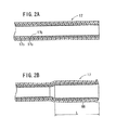
この燃料ホース17について、図2を参照して詳述する。図2Aは、本実施形態に係る燃料ホース17の断面図であり、図2Bは、燃料ホース17をジョイント44の燃料ホース挿入部46に圧入して接続する前に、当該燃料ホース17が拡径された状態を示す断面図である。
The
図2Aに示すように、燃料ホース17は、例えば、肉厚0.55mmで内径2.5mmのPA12(ポリアミド12)からなる管17aと、該管17aの内側に層状に設けられ、肉厚0.2mmのETFE(テトラフルオロエチレン−エチレン共重合体)からなる内管17bと、管17aを紫外線、強酸及びチッピング等から保護するために設けられ、肉厚1.0mmのEPDM(エチレン−プロピレンゴム)からなる保護管17cとにより形成される。そして、このような燃料ホース17を、ジョイント44の燃料ホース挿入部46に圧入する際には、図2Bに示すように、燃料ホース挿入部46が挿入される端部から所定長さLの部分を拡径し、拡径部66を形成する。
As shown in FIG. 2A, the
燃料ホース17は、上記のような樹脂製材料を使用しているため、従来から広く使用されているゴム材料に比べて、熱や燃料による劣化を大幅に抑制可能である。
Since the
一方、樹脂製材料は一般に前記ゴム材料に比べて弾性が小さい。また、燃料ホース挿入部46の外径を、燃料ホース17の内径よりも若干大きく、例えば管17aの内径2.5mm程度に構成すると、燃料ホース17と燃料ホース挿入部46との密着性が向上するため好適である。そこで、本実施形態に係る燃料ホース17では、該燃料ホース17の端部から所定長さLの部分を予め拡径して拡径部66を形成しておくことにより、燃料ホース挿入部46を燃料ホース17に容易に挿入することができ、燃料ホース17と燃料ホース挿入部46との密着性を高めながら、これらの接続作業の効率を向上させることができる。
On the other hand, the resin material is generally less elastic than the rubber material. Further, when the outer diameter of the fuel
また、図1に示すように、燃料ホース挿入部46の外周面には溝部68が環状に設けられ、該溝部68には、シール部材69として例えばOリングが配設されている。このため、燃料ホース17と燃料ホース挿入部46との密着性が一層高まると共に、経年的に生じるクリープに起因する燃料ホース17の燃料ホース挿入部46からの脱抜や、燃料ホース17と燃料ホース挿入部46との間における液漏れ等を防止することができる。
Further, as shown in FIG. 1, a
次に、以上のように構成される燃料噴射弁装置システム10aにおいて、吸気管14に、燃料噴射弁装置16及び燃料供給管18を接続する手順について、図3を参照して説明する。図3は、燃料噴射弁装置システム10aにおける各構成部品の接続手順を説明するための一部切欠縦断面図である。なお、この場合、燃料ホース17と燃料供給管18のジョイント44とは予め連結され、一体に構成されているものとする。
Then, the fuel
先ず、吸気管14に燃料噴射弁装置16を接続する。この場合、吸気管14の装着孔12に、燃料噴射弁装置16のノズル部30が挿入されると共に、フランジ部48に形成されているボルト挿通孔50を介して、ボルト24がねじ部26に締結される。このため、燃料噴射弁装置16が吸気管14に容易且つ確実に固定される。また、ノズル部30の先端に形成される噴射口34が吸気流路20内を指向することにより、燃料噴射弁装置16から吸気流路20内に燃料を噴射することが可能となる。
First, the fuel
次に、上記のように、吸気管14に固定された燃料噴射弁装置16の接続管32に、燃料供給管18を接続する。この場合、燃料噴射弁装置16が吸気管14に固定されているため、リテーナ45を介してジョイント44の内部に、接続管32を容易に、そして確実に挿入することができる。
Next, the
また、このとき、接続管32の拡径部40とリテーナ45の係止爪56とが係合し、さらに、突起部57と孔部58の側面58aとが係合する。このため、リテーナ45が固定され、ジョイント44が接続管32から脱抜することが阻止さるため、より一層確実に、燃料噴射弁装置16と燃料供給管18とが接続される。
At this time, the
以上のように、本実施形態に係る燃料噴射弁装置システム10aでは、吸気管14に燃料噴射弁装置16を固定し、燃料噴射弁装置16に突設される接続管32に、燃料供給管18のジョイント44を接続するように構成している。このため、上記従来の構成にて用いられている固定ホルダを設ける必要がなく、部品点数が削減でき、小型化及び生産コスト低減が可能となる。
As described above, in the fuel injection
また、燃料ホース17に樹脂製材料を用いる場合には、上記のように燃料ホース17を燃料ホース挿入部46に圧入して連結する等の作業が必要であり、例えば図示しない内燃機関を搭載した二輪車や四輪車等にて、このような圧入作業を実施することは作業効率上好ましくない。
Further, when a resin material is used for the
そこで、本実施形態では、予め燃料ホース17と燃料供給管18とを一体に連結しておく一方、吸気管14に燃料噴射弁装置16を固定しておくことで、燃料供給管18を接続管32に容易に接続可能である。このため、燃料ホース17に樹脂製材料を用いる場合にも、燃料噴射弁装置システム10aの接続を容易に行うことができ、作業効率を向上させることができると共に、燃料ホース17の熱や燃料による劣化を大幅に抑制することができる。また、ジョイント44により、燃料供給管18を燃料噴射弁装置16から容易に着脱することができるため、燃料噴射弁装置16の取り付け性やメンテナンス性が向上し、さらに、燃料供給管18の配管作業の効率が向上する。
Therefore, in the present embodiment, the
次に、本発明の第2の実施形態につき、図5及び図6を参照して説明する。図5は、本発明の第2の実施形態に係る燃料噴射弁装置システム10bの一部切欠縦断面図を示している。なお、図5において、図1〜図4に示される参照符号と同一の参照符号は、同一又は同様な構成を示し、このため同一又は同様な機能及び効果を奏するものとして、その詳細な説明を省略し、以下同様とする。
Next, a second embodiment of the present invention will be described with reference to FIGS. FIG. 5 shows a partially cutaway longitudinal sectional view of a fuel injection
本実施形態に係る燃料噴射弁装置システム10bは、上記実施形態に係る燃料噴射弁装置システム10aと比べて、燃料噴射弁装置16の替わりに燃料噴射弁装置72を備える点が相違する。そして、燃料噴射弁装置72は、燃料噴射弁装置16と比べて、ハウジング部28の替わりにハウジング部74を備える点が相違する。
The fuel injection
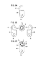
ハウジング部74は、略円筒形状からなり、上記ハウジング部28においてフランジ部48が設けられる部分付近の外周面には環状の溝部76が形成されている。そして、薄板により構成され、フック部81を有し且つボルト挿通孔78が設けられるフランジプレート80(図6A参照)が、図6B及び図6Cに示す向きに溝部76を挟み込むように2枚重ねで使用され、これらのボルト挿通孔78が一括してボルト24により締結されることで、燃料噴射弁装置72が吸気管14に固定される。
The
なお、フランジプレート80を1枚用いて、該フランジプレート80をハウジング部74の溝部76に接着や溶接等により固定することで、ハウジング部74とフランジプレート80とを一体として構成してもよい。
Note that the
以上のように、本実施形態に係る燃料噴射弁装置システム10bによれば、フランジプレート80により、燃料噴射弁装置72を吸気管14に固定するようにしているため、フランジ部48が削減でき、燃料噴射弁装置72の形状が簡略化され、該燃料噴射弁装置72の製造コストを低減することができる。また、ボルト24をねじ部26から若干緩めるだけで、フランジプレート80とハウジング部74とを分離することができるため、メンテナンス性が一層向上する。
As described above, according to the fuel injection
次に、本発明の第3の実施形態につき、図7を参照して説明する。図7は、本発明の第3の実施形態に係る燃料噴射弁装置システム10cの一部切欠縦断面図を示している。
Next, a third embodiment of the present invention will be described with reference to FIG. FIG. 7 shows a partially cutaway longitudinal sectional view of a fuel injection
本実施形態に係る燃料噴射弁装置システム10cは、上記実施形態に係る燃料噴射弁装置システム10aと比べて、燃料噴射弁装置16の替わりに燃料噴射弁装置82を備えると共に、燃料供給管18の替わりに燃料供給管84を備える点が相違する。そして、燃料噴射弁装置82は、燃料噴射弁装置16と比べて、フランジ部48を有しない略円筒形状のハウジング部86を備える点が相違する。また、燃料供給管84は、燃料供給管18と比べて、ジョイント44の替わりにジョイント90を備える点が相違する。
The fuel injection
ジョイント90の孔部58近傍には、ボルト挿通孔92を有するフランジ部94が形成されている。該フランジ部94は、上記燃料噴射弁装置16におけるフランジ部48と略同形状である。
Near the
このため、本実施形態では、吸気管14の装着孔12に燃料噴射弁装置82のノズル部30を装着した後、燃料供給管84と接続管32とを接続する際、フランジ部94のボルト挿通孔92を介して、ボルト24により、燃料供給管84及び燃料噴射弁装置82を一括して固定する。
Therefore, in the present embodiment, when the
以上のように、本実施形態に係る燃料噴射弁装置システム10cによれば、ジョイント90に形成されるフランジ部94により、燃料供給管84及び燃料噴射弁装置82を一括して吸気管14に固定するように構成している。このため、燃料供給管84と燃料噴射弁装置82との接続部において、燃料供給管84に揺れやがたつきが生じることを防止でき、例えば、燃料ホース17を前記内燃機関の所定の部材に固定する作業等を省略することができる。さらに、フランジ部48が削減できるため、燃料噴射弁装置82の形状が簡略化され、該燃料噴射弁装置82の製造コストを一層低減することができる。
As described above, according to the fuel injection
以上、上記各実施形態により本発明を説明したが、本発明はこれに限定されるものではなく、本発明の要旨を逸脱することなく、種々の構成を採り得ることは当然可能である。 Although the present invention has been described above by the above embodiments, the present invention is not limited to this, and it is naturally possible to adopt various configurations without departing from the gist of the present invention.
例えば、燃料ホース17としては、ガソリン等の燃料を流通させる燃料ホースに要求される特性を満足させるものであれば特に限定されないが、上記実施形態にて説明した、管17a、内管17b及び保護管17cからなる層状のものが好適である。また、燃料ホース17及び燃料供給管18、84の材質は、樹脂製材料であれば特に限定されないが、ポリアミド系樹脂、フッ素系樹脂等が好適に使用できる。
For example, the
また、燃料噴射弁装置16は吸気管14に装着するものとしたが、これに限らず、燃料噴射弁装置16のノズル部30が、上記燃焼室への吸気通路を指向するように、当該燃焼室のシリンダヘッド等に直付けするようにしてもよい。
Although the fuel
10a、10b、10c…燃料噴射弁装置システム
12…装着孔 14…吸気管
16、72、82…燃料噴射弁装置 17…燃料ホース
18、84…燃料供給管 20…吸気流路
22…スロットルバルブ 24…ボルト
26…ねじ部 28、74、86…ハウジング部
30…ノズル部 32…接続管
34…噴射口 36…弁体
38、54…流路 44、90…ジョイント
46…燃料ホース挿入部 48、94…フランジ部
50、78、92…ボルト挿通孔 80…フランジプレート
DESCRIPTION OF
Claims (3)
前記燃料ホース(17)に一体的に連結される燃料供給管(18、84)と、
内燃機関の燃焼室に燃料を供給するための噴射口(34)が設けられたノズル部(30)を備える燃料噴射弁装置(16、72、82)と、
前記燃焼室に連通する吸気通路(20)とを備え、
前記ノズル部(30)が前記吸気通路(20)に向けて装着され、
前記燃料噴射弁装置(16、72、82)には、流入する燃料を前記噴射口(34)に供給する流路(38、54)が設けられた燃料噴射弁装置システム(10a、10b、10c)において、
前記燃料噴射弁装置(16、72、82)は、前記流路(38、54)の軸方向における一方の端部には燃料を取り入れる接続管(32)が設けられ、他方の端部には前記ノズル部(30)が設けられているハウジング部(28、74、86)を備え、
前記燃料供給管(18、84)又は前記ハウジング部(28、74、86)にはフランジ部(48、94)が設けられると共に、前記フランジ部(48、94)を介して、前記燃料噴射弁装置(16、72、82)が前記吸気通路(20)に固定され、
前記燃料供給管(18、84)の内部にはリテーナ(45)が設けられ、前記燃料供給管(18、84)の側壁に設けられた孔部(58)に前記リテーナ(45)の外側に設けた突起部(57)が係合し、
前記接続管には拡径部(40、66)が設けられ、前記燃料供給管(18、84)を前記接続管(32)に接続したとき、前記燃料供給管(18、84)内部の前記リテーナ(45)の先端の係止爪(56)が前記拡径部(40、66)に係止して、抜け止めをなすようにしたことを特徴とする燃料噴射弁装置システム(10a、10b、10c)。 A fuel hose (17) for sending fuel from the fuel tank ;
Fuel supply pipe which is integrally connected to the front Symbol fuel hose (17) and (18,84),
A fuel injection valve device comprising a nozzle part which injection port for supplying fuel to the combustion chamber of the internal combustion engine (34) is provided (30) (16,72,82),
An intake passage (20) communicating with the combustion chamber,
The nozzle portion (30) is mounted toward the intake passage (20) ;
The fuel in the injection valve device (16,72,82), and supplies channel to the injection port of the fuel inflows (34) (38, 54) is a fuel injection valve device system provided (10a, 10b, 10c)
The fuel injection valve device (16, 72, 82) is provided with a connecting pipe (32) for taking in fuel at one end in the axial direction of the flow path (38, 54) , and at the other end. A housing portion (28, 74, 86) provided with the nozzle portion (30) ;
The fuel supply pipe (18, 84) or the housing part (28, 74, 86) is provided with flange parts (48, 94) , and the fuel injection valve is provided via the flange parts (48, 94). A device (16, 72, 82) is fixed to the intake passage (20) ;
A retainer (45) is provided inside the fuel supply pipe (18, 84), and a hole (58) provided in a side wall of the fuel supply pipe (18, 84) is provided outside the retainer (45). The provided protrusion (57) is engaged,
The connection pipe is provided with an enlarged diameter portion (40, 66), and when the fuel supply pipe (18, 84) is connected to the connection pipe (32), the inside of the fuel supply pipe (18, 84). The fuel injection valve device system (10a, 10b) is characterized in that a locking claw (56) at the tip of the retainer (45) is locked to the enlarged diameter portion (40, 66) to prevent the retainer (45) from coming off. 10c) .
前記燃料ホース(17)と前記燃料供給管(18、84)とは、樹脂製材料により構成されていることを特徴とする燃料噴射弁装置システム(10a、10b、10c)。 Claim 1 fuel injector system as described (10a, 10b, 10c) in,
The fuel injection valve device system (10a, 10b, 10c), wherein the fuel hose (17) and the fuel supply pipe (18, 84) are made of a resin material.
前記燃料ホース(17)と前記燃料供給管(18、84)とは、圧入により一体的に連結されていることを特徴とする燃料噴射弁装置システム(10a、10b、10c)。 The fuel injection device system (10a, 10b, 10c) according to claim 1 or 2,
The fuel injection valve device system (10a, 10b, 10c), wherein the fuel hose (17) and the fuel supply pipe (18, 84) are integrally connected by press fitting.
Priority Applications (6)
| Application Number | Priority Date | Filing Date | Title |
|---|---|---|---|
| JP2005377673A JP4344727B2 (en) | 2005-12-28 | 2005-12-28 | Fuel injector system |
| TW095140279A TW200724781A (en) | 2005-12-28 | 2006-10-31 | Fuel injection system and the injection valve |
| ES06127006T ES2356557T3 (en) | 2005-12-28 | 2006-12-22 | FUEL INJECTION SYSTEM AND FUEL INJECTION VALVE DEVICE USED IN A FUEL INJECTION SYSTEM. |
| MYPI20064760 MY144149A (en) | 2005-12-28 | 2006-12-22 | Fuel injection system and fuek injection valve device used in fuel injection system |
| EP20060127006 EP1803928B1 (en) | 2005-12-28 | 2006-12-22 | Fuel injection system and fuel injection valve device used in fuel injection system |
| CN2006101711114A CN1991161B (en) | 2005-12-28 | 2006-12-22 | Fuel injection system and fuel injection valve device used in fuel injection system |
Applications Claiming Priority (1)
| Application Number | Priority Date | Filing Date | Title |
|---|---|---|---|
| JP2005377673A JP4344727B2 (en) | 2005-12-28 | 2005-12-28 | Fuel injector system |
Publications (2)
| Publication Number | Publication Date |
|---|---|
| JP2007177711A JP2007177711A (en) | 2007-07-12 |
| JP4344727B2 true JP4344727B2 (en) | 2009-10-14 |
Family
ID=37909759
Family Applications (1)
| Application Number | Title | Priority Date | Filing Date |
|---|---|---|---|
| JP2005377673A Expired - Fee Related JP4344727B2 (en) | 2005-12-28 | 2005-12-28 | Fuel injector system |
Country Status (6)
| Country | Link |
|---|---|
| EP (1) | EP1803928B1 (en) |
| JP (1) | JP4344727B2 (en) |
| CN (1) | CN1991161B (en) |
| ES (1) | ES2356557T3 (en) |
| MY (1) | MY144149A (en) |
| TW (1) | TW200724781A (en) |
Families Citing this family (4)
| Publication number | Priority date | Publication date | Assignee | Title |
|---|---|---|---|---|
| JP5502541B2 (en) * | 2010-03-19 | 2014-05-28 | 株式会社ケーヒン | Mounting structure of fuel injection valve |
| DE102016225695A1 (en) * | 2016-12-21 | 2018-06-21 | Robert Bosch Gmbh | Arrangement with at least one valve and a holder |
| WO2019064500A1 (en) * | 2017-09-29 | 2019-04-04 | 本田技研工業株式会社 | Mounting structure for injector |
| JP7403572B2 (en) | 2022-03-31 | 2023-12-22 | 本田技研工業株式会社 | fuel injection valve device |
Family Cites Families (4)
| Publication number | Priority date | Publication date | Assignee | Title |
|---|---|---|---|---|
| DE2614288A1 (en) * | 1976-04-02 | 1977-10-06 | Bayerische Motoren Werke Ag | Fuel injector fitting system - is for indirect fuel injection and has fixing clamp with widened bolt borings |
| DE3806906A1 (en) * | 1988-03-03 | 1989-09-14 | Opel Adam Ag | Device for fixing a fuel injection valve injecting into an intake port of an internal combustion engine |
| JP3841258B2 (en) * | 2000-03-29 | 2006-11-01 | 本田技研工業株式会社 | Engine with injector soundproof cover |
| JP4405111B2 (en) * | 2001-08-06 | 2010-01-27 | 株式会社ケーヒン | Fuel injector holding device |
-
2005
- 2005-12-28 JP JP2005377673A patent/JP4344727B2/en not_active Expired - Fee Related
-
2006
- 2006-10-31 TW TW095140279A patent/TW200724781A/en not_active IP Right Cessation
- 2006-12-22 MY MYPI20064760 patent/MY144149A/en unknown
- 2006-12-22 CN CN2006101711114A patent/CN1991161B/en active Active
- 2006-12-22 EP EP20060127006 patent/EP1803928B1/en not_active Expired - Fee Related
- 2006-12-22 ES ES06127006T patent/ES2356557T3/en active Active
Also Published As
| Publication number | Publication date |
|---|---|
| TW200724781A (en) | 2007-07-01 |
| CN1991161B (en) | 2011-06-08 |
| MY144149A (en) | 2011-08-15 |
| CN1991161A (en) | 2007-07-04 |
| EP1803928B1 (en) | 2010-11-17 |
| EP1803928A3 (en) | 2009-03-18 |
| TWI326739B (en) | 2010-07-01 |
| ES2356557T3 (en) | 2011-04-11 |
| EP1803928A2 (en) | 2007-07-04 |
| JP2007177711A (en) | 2007-07-12 |
Similar Documents
| Publication | Publication Date | Title |
|---|---|---|
| TWI481778B (en) | Fuel pump module having a direct mounted jet pump and methods of assembly | |
| US7802558B2 (en) | Fuel delivery system | |
| JP4344727B2 (en) | Fuel injector system | |
| JP2005226641A (en) | Fuel transfer device | |
| KR20080047275A (en) | Pump for a fluid medium, in particular for manual use in internal combustion engines operated with diesel fuel | |
| JP2010006246A (en) | Fuel supply device | |
| JP2011131824A (en) | Fuel feeding device | |
| US8997715B2 (en) | Common rail system with leak containment and detection | |
| US20110232609A1 (en) | Integrated fuel injector orientation and retention device | |
| JP3846337B2 (en) | Injector fixing method and injector fixing device | |
| JP2010116794A (en) | Intake system for internal combustion engine | |
| US20170122278A1 (en) | End seal structure of a fuel rail for a gasoline direct injection engine | |
| US10012192B2 (en) | End seal structure of a fuel rail for a gasoline direct injection engine | |
| TW200410859A (en) | Air inlet device of engine | |
| JP7011310B2 (en) | Connector with pulsation absorption function | |
| KR100951058B1 (en) | Receptacle connector assembly | |
| JP2011025854A (en) | Pipe connector for fuel tank | |
| JP4885937B2 (en) | Fuel injector assembly | |
| US20130334810A1 (en) | Convolute Tube With Integrated Preformed Angle Fitting | |
| US9638151B2 (en) | Flow-through fitting and filter assembly | |
| JP2009264507A (en) | Oil supply device | |
| CN104564415B (en) | The sealing system of engine | |
| JP5338617B2 (en) | Tubing covering structure | |
| JP2002039034A (en) | Supporting construction of electromagnetic fuel injection valve | |
| JP2008057388A (en) | Vaporized fuel distribution member |
Legal Events
| Date | Code | Title | Description |
|---|---|---|---|
| A621 | Written request for application examination |
Free format text: JAPANESE INTERMEDIATE CODE: A621 Effective date: 20071127 |
|
| A131 | Notification of reasons for refusal |
Free format text: JAPANESE INTERMEDIATE CODE: A131 Effective date: 20081014 |
|
| A521 | Request for written amendment filed |
Free format text: JAPANESE INTERMEDIATE CODE: A523 Effective date: 20081205 |
|
| A131 | Notification of reasons for refusal |
Free format text: JAPANESE INTERMEDIATE CODE: A131 Effective date: 20090210 |
|
| A521 | Request for written amendment filed |
Free format text: JAPANESE INTERMEDIATE CODE: A523 Effective date: 20090410 |
|
| TRDD | Decision of grant or rejection written | ||
| A01 | Written decision to grant a patent or to grant a registration (utility model) |
Free format text: JAPANESE INTERMEDIATE CODE: A01 Effective date: 20090707 |
|
| A01 | Written decision to grant a patent or to grant a registration (utility model) |
Free format text: JAPANESE INTERMEDIATE CODE: A01 |
|
| A61 | First payment of annual fees (during grant procedure) |
Free format text: JAPANESE INTERMEDIATE CODE: A61 Effective date: 20090713 |
|
| FPAY | Renewal fee payment (event date is renewal date of database) |
Free format text: PAYMENT UNTIL: 20120717 Year of fee payment: 3 |
|
| R150 | Certificate of patent or registration of utility model |
Ref document number: 4344727 Country of ref document: JP Free format text: JAPANESE INTERMEDIATE CODE: R150 Free format text: JAPANESE INTERMEDIATE CODE: R150 |
|
| FPAY | Renewal fee payment (event date is renewal date of database) |
Free format text: PAYMENT UNTIL: 20120717 Year of fee payment: 3 |
|
| FPAY | Renewal fee payment (event date is renewal date of database) |
Free format text: PAYMENT UNTIL: 20130717 Year of fee payment: 4 |
|
| FPAY | Renewal fee payment (event date is renewal date of database) |
Free format text: PAYMENT UNTIL: 20140717 Year of fee payment: 5 |
|
| R250 | Receipt of annual fees |
Free format text: JAPANESE INTERMEDIATE CODE: R250 |
|
| LAPS | Cancellation because of no payment of annual fees |