JP4342425B2 - Wireless communication device - Google Patents
Wireless communication device Download PDFInfo
- Publication number
- JP4342425B2 JP4342425B2 JP2004328808A JP2004328808A JP4342425B2 JP 4342425 B2 JP4342425 B2 JP 4342425B2 JP 2004328808 A JP2004328808 A JP 2004328808A JP 2004328808 A JP2004328808 A JP 2004328808A JP 4342425 B2 JP4342425 B2 JP 4342425B2
- Authority
- JP
- Japan
- Prior art keywords
- signal
- frequency
- unit
- transmission
- distortion
- Prior art date
- Legal status (The legal status is an assumption and is not a legal conclusion. Google has not performed a legal analysis and makes no representation as to the accuracy of the status listed.)
- Expired - Fee Related
Links
Images


Classifications
-
- H—ELECTRICITY
- H04—ELECTRIC COMMUNICATION TECHNIQUE
- H04L—TRANSMISSION OF DIGITAL INFORMATION, e.g. TELEGRAPHIC COMMUNICATION
- H04L27/00—Modulated-carrier systems
- H04L27/26—Systems using multi-frequency codes
- H04L27/2601—Multicarrier modulation systems
- H04L27/2626—Arrangements specific to the transmitter only
- H04L27/2627—Modulators
- H04L27/2637—Modulators with direct modulation of individual subcarriers
-
- H—ELECTRICITY
- H03—ELECTRONIC CIRCUITRY
- H03F—AMPLIFIERS
- H03F1/00—Details of amplifiers with only discharge tubes, only semiconductor devices or only unspecified devices as amplifying elements
- H03F1/32—Modifications of amplifiers to reduce non-linear distortion
-
- H—ELECTRICITY
- H03—ELECTRONIC CIRCUITRY
- H03F—AMPLIFIERS
- H03F1/00—Details of amplifiers with only discharge tubes, only semiconductor devices or only unspecified devices as amplifying elements
- H03F1/32—Modifications of amplifiers to reduce non-linear distortion
- H03F1/3241—Modifications of amplifiers to reduce non-linear distortion using predistortion circuits
- H03F1/3247—Modifications of amplifiers to reduce non-linear distortion using predistortion circuits using feedback acting on predistortion circuits
-
- H—ELECTRICITY
- H03—ELECTRONIC CIRCUITRY
- H03F—AMPLIFIERS
- H03F1/00—Details of amplifiers with only discharge tubes, only semiconductor devices or only unspecified devices as amplifying elements
- H03F1/32—Modifications of amplifiers to reduce non-linear distortion
- H03F1/3241—Modifications of amplifiers to reduce non-linear distortion using predistortion circuits
- H03F1/3294—Acting on the real and imaginary components of the input signal
-
- H—ELECTRICITY
- H04—ELECTRIC COMMUNICATION TECHNIQUE
- H04L—TRANSMISSION OF DIGITAL INFORMATION, e.g. TELEGRAPHIC COMMUNICATION
- H04L27/00—Modulated-carrier systems
- H04L27/32—Carrier systems characterised by combinations of two or more of the types covered by groups H04L27/02, H04L27/10, H04L27/18 or H04L27/26
- H04L27/34—Amplitude- and phase-modulated carrier systems, e.g. quadrature-amplitude modulated carrier systems
- H04L27/36—Modulator circuits; Transmitter circuits
- H04L27/366—Arrangements for compensating undesirable properties of the transmission path between the modulator and the demodulator
- H04L27/367—Arrangements for compensating undesirable properties of the transmission path between the modulator and the demodulator using predistortion
- H04L27/368—Arrangements for compensating undesirable properties of the transmission path between the modulator and the demodulator using predistortion adaptive predistortion
-
- H—ELECTRICITY
- H03—ELECTRONIC CIRCUITRY
- H03F—AMPLIFIERS
- H03F2200/00—Indexing scheme relating to amplifiers
- H03F2200/111—Indexing scheme relating to amplifiers the amplifier being a dual or triple band amplifier, e.g. 900 and 1800 MHz, e.g. switched or not switched, simultaneously or not
-
- H—ELECTRICITY
- H03—ELECTRONIC CIRCUITRY
- H03F—AMPLIFIERS
- H03F2201/00—Indexing scheme relating to details of amplifiers with only discharge tubes, only semiconductor devices or only unspecified devices as amplifying elements covered by H03F1/00
- H03F2201/32—Indexing scheme relating to modifications of amplifiers to reduce non-linear distortion
- H03F2201/3206—Multiple channels are combined and amplified by only one amplifier
-
- H—ELECTRICITY
- H04—ELECTRIC COMMUNICATION TECHNIQUE
- H04B—TRANSMISSION
- H04B1/00—Details of transmission systems, not covered by a single one of groups H04B3/00 - H04B13/00; Details of transmission systems not characterised by the medium used for transmission
- H04B1/02—Transmitters
- H04B1/04—Circuits
- H04B1/0475—Circuits with means for limiting noise, interference or distortion
-
- H—ELECTRICITY
- H04—ELECTRIC COMMUNICATION TECHNIQUE
- H04B—TRANSMISSION
- H04B1/00—Details of transmission systems, not covered by a single one of groups H04B3/00 - H04B13/00; Details of transmission systems not characterised by the medium used for transmission
- H04B1/02—Transmitters
- H04B1/04—Circuits
- H04B1/0483—Transmitters with multiple parallel paths
Landscapes
- Engineering & Computer Science (AREA)
- Physics & Mathematics (AREA)
- Nonlinear Science (AREA)
- Power Engineering (AREA)
- Computer Networks & Wireless Communication (AREA)
- Signal Processing (AREA)
- Transmitters (AREA)
- Digital Transmission Methods That Use Modulated Carrier Waves (AREA)
- Cable Transmission Systems, Equalization Of Radio And Reduction Of Echo (AREA)
Description
本発明は無線通信装置に係わり、特に、キャリアを低周波側と高周波側の2系統に分け、各系統毎に無線で信号を送信するための処理を行なう送信部と該送信部で発生する歪を補償する歪補償部を備え、多数のキャリア信号を無線で送信する無線通信装置に関する。 The present invention relates to a radio communication apparatus, and in particular, a carrier is divided into two systems, a low frequency side and a high frequency side, and a transmission unit that performs processing for transmitting a signal wirelessly for each system and distortion generated in the transmission unit The present invention relates to a wireless communication apparatus that includes a distortion compensation unit that compensates for a large number of carrier signals.
移動体通信システムの発展に伴い、無線通信装置に要求される送受信信号量が増えてきている。多数のキャリアを隣接して送信するマルチキャリア方式の無線通信装置では、送受信信号量の増大に対してキャリア数を増設するのが一般的である。
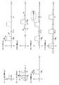
図5は従来の第1のマルチキャリア方式の無線通信装置の構成図、図6は動作説明図であり、(1)〜(7)は図5の同一番号を付した部分のスペクトラムを示している。
キャリア毎に設けられた信号処理部11〜1nのべースバンド処理部(BB)1aは、送信すべきデータに対して誤り訂正/検出符号の付加、インタリーブ、多値変調、符号拡散などのべースバンド信号処理を施し、複素のべースバンド信号を出力する。ルートナイキストフィルタ1b、1cはべースバンド処理部1aから入力する複素べースバンド信号の実数部と虚数部にルートナイキストフィルタ処理を施し(図6の(1)参照)、キャリアシフト部1c,1dはべースバンド信号の実数部と虚数部にexp(jωjt)(j=1〜n)を乗算して角周波数ωjのキャリア信号にして出力する(図6の(2)参照)。
With the development of mobile communication systems, the amount of transmission / reception signals required for wireless communication devices has increased. In a multi-carrier wireless communication apparatus that transmits a large number of carriers adjacent to each other, it is common to increase the number of carriers in response to an increase in the amount of transmitted / received signals.
FIG. 5 is a block diagram of a conventional first multicarrier radio communication apparatus, FIG. 6 is a diagram for explaining the operation, and (1) to (7) show the spectrum of the part given the same number in FIG. Yes.
Baseband processor mentioned
合成部2a,2bは各キャリアの同相分、直交分毎に合成し、キャリア合成信号の同相成分Ich及び直交成分Qchを出力し、歪補償部(適応形プリディストータAPD: Adaptive Predistortion Device)3は、送信増幅器(後述する)で発生する歪を補償する歪補償信号を発生し、演算部4a,4bは該歪補償信号をキャリア合成信号の同相成分Ich及び直交成分Qchに加算して直交変調部5に入力する。直交変調部5はキャリア合成信号の周波数帯域幅をW0とするとき、周波数が1.5×W0のローカル信号を用いて該キャリア合成信号に直交変調を施す(図6の(3)参照)。この直交変調により各キャリア周波数は1.5×W0アップした中間周波信号になる。
DA変換器6は直交変調部5から出力する信号をサンプリング周波数Fsでアナログに変換し、ローパスフィルタ7は不必要な高域成分を除去し(図6の(4)参照)、ミキサ8は、入力信号にローカル発振器9から出力するローカル信号を乗算して周波数(f0+1.5×W0)の無線信号にアップコンバートする。送信増幅器10は周波数アップコンバートされた無線信号を増幅し、アンテナを介して送信する(図6の(5)参照)。
The synthesizing
The
送信増幅器10において図6の(5)に示すように主信号の両側に歪D1,D2が発生する。この歪D1,D2を補償するために、方向結合器11は送信信号の一部を抽出し、ミキサ12は入力信号にローカル発振器9から出力するローカル信号を乗算して周波数1.5×W0の中間周波信号にダウンコンバートし、AD変換器13は周波数Fs=6×W0で入力信号をサンプリングしてディジタル変換する(図6の(6)参照)。サンプリング周波数FsでAD変換することにより、高次スペクトラムが発生する(イメージ出現)。直交復調部14は周波数が1.5×W0のローカル信号を用いてAD変換器の出力信号に直交復調を施し(図6の(7)参照)、復調信号を歪補償部3に入力する。
In the
歪補償部3は適応アルゴリズムを用いて送信増幅器10の歪みを除去するための歪補償信号を発生してを送信信号に付加し、主信号の両側の歪D1,D2(図6の(5)参照)を除去する。図7は適応型プリディストータである歪補償部3の構成例である。乗算器3aは合成部2a,2bから出力する送信信号x(t)に歪補償係数hn−1(p)を乗算し、演算部4は送信信号x(t)から歪補償信号hn−1・x(t)を減算して補償後の信号(=hn(p)x(t)−x(t))を出力する。演算部3bは送信信号x(t)のパワーp(=x(t)2)を演算し、歪補償係数記憶部3cは送信信号x(t)の各パワーに応じた歪補償係数h(p)を記憶し、送信信号x(t)のパワーpに応じた歪補償係数hn−1(p)を出力する。又、歪補償係数記憶部3cは、LMSアルゴリズムにより求まる歪補償係数hn(p)で歪補償係数hn−1(p)を更新する。共役複素信号出力部3dは直交復調部14から入力する帰還復調信号y(t)の共役複素信号を出力し、減算器3eは送信信号x(t)と帰還復調信号y(t)の差e(t)を出力する。乗算器3fはhn−1(p)とy*(t)の乗算を行ってu*(t)を出力し、乗算器3gはe(t)とu*(t)の乗算を行い、乗算器3hはステップサイズパラメータμを乗算器3gの出力信号に乗算し、加算器3iはhn−1(p)とμe(t)u*(t)を加算して歪補償係数記憶部3cに入力する。上記構成により以下のLMSアルゴリズムに従った演算が行われる。
hn(p)=hn−1(p)+μe(t)u*(t) (1)
e(t)=x(t)−y(t)
y(t)=hn−1(p)x(t)f(p)
u(t)=x(t)f(p)≒h* n−1(p)y(t) hn−1(p)h* n−1(p)≒1
p=|x(t)|2
ただし、
x(t):送信信号
f(p):送信増幅器の歪関数
h(p):推定歪補償係数
μ :ステップサイズ・パラメータ
y(t):帰還信号
u(t):歪みを受けた信号
x,y,f,h,u,eは複素数、*は共役複素数である。u(t)はアンプの振幅歪みがあまり大きくないと仮定して(hn−1(p)・h* n−1(p)≒1)、近似する。上記演算処理を行うことにより、送信信号x(t)と帰還信号y(t)の差e(t)のパワーが最小となるように歪補償係数h(p)が(1)式により更新され、最終的に最適の歪補償係数値に収束し、送信増幅器10の歪が補償される
The
h n (p) = h n−1 (p) + μe (t) u * (t) (1)
e (t) = x (t) -y (t)
y (t) = h n-1 (p) x (t) f (p)
u (t) = x (t) f (p) ≈h * n−1 (p) y (t) h n−1 (p) h * n−1 (p) ≈1
p = | x (t) | 2
However,
x (t): transmission signal f (p): distortion function of transmission amplifier h (p): estimated distortion compensation coefficient μ: step size parameter y (t): feedback signal u (t): signal subjected to distortion x , Y, f, h, u, e are complex numbers, and * is a conjugate complex number. u (t) is approximated assuming that the amplitude distortion of the amplifier is not very large (h n−1 (p) · h * n−1 (p) ≈1). By performing the above arithmetic processing, the distortion compensation coefficient h (p) is updated by the equation (1) so that the power of the difference e (t) between the transmission signal x (t) and the feedback signal y (t) is minimized. Finally, it converges to the optimum distortion compensation coefficient value, and the distortion of the
図5の構成により、キャリア数を増大しようとすると、ディジタル信号処理部、特にDA変換、AD変換のサンプリング周波数Fsの限界が問題となってくる。例えばキャリア数を2倍にするには、ディジタル部のサンプリング周波数Fsが2倍(Fs=12×W0)必要となる。すなわち、キャリア数を2倍にする前のサンプリング周波数Fsは図6より6W0であるから、キャリア数を2倍にするとFs=12×W0となる。 When trying to increase the number of carriers with the configuration of FIG. 5, the limit of the sampling frequency Fs of the digital signal processing unit, particularly DA conversion and AD conversion, becomes a problem. For example, in order to double the number of carriers, the sampling frequency Fs of the digital part needs to be doubled (Fs = 12 × W 0 ). That is, since the sampling frequency Fs before doubling the number of carriers is 6W 0 from FIG. 6, doubling the number of carriers results in Fs = 12 × W 0 .
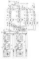
以上より、一般的にAD変換器のサンプリング周波数がネックとなり、これ以上周波数を上げられない場合、図8に示すように、キャリアを低周波側と高周波側の2系統に分け、各系統毎に無線で信号を送信するための処理を行ない、送信増幅器10,10′の後段でバンドパスフィルタ(BPF)21,22を通して結合することが考えられる。なお、図8の無線通信装置は、周知技術ではない。
図8のマルチキャリア方式の無線通信装置において、低周波側の送信部(図8の上側の送信部)は図5の第1従来例と同じであり、同一番号を付している。又、高周波側の送信部(図8の下側の送信部)も構成的に図5の第1従来例と同じであり、同一番号に′を付している。DA変換器6,6′、AD変換器13,13′のサンプリング周波数Fsは6×W0で、キャリア数を増大しない前と同じ周波数である。高周波側の送信部が低周波側の送信部と異なる点は、低周波側のローカル発振器9が周波数f0のローカル信号を発生するのに対して、高周波側のローカル発振器9′が周波数(f0+W0)のローカル信号を発生する点である。
As described above, generally, when the sampling frequency of the AD converter becomes a bottleneck and the frequency cannot be increased any more, as shown in FIG. 8, the carrier is divided into two systems of the low frequency side and the high frequency side, It is conceivable to perform processing for transmitting a signal wirelessly and to combine the signals through band-pass filters (BPF) 21 and 22 after the
In the multicarrier wireless communication apparatus of FIG. 8, the low frequency side transmission unit (the upper transmission unit of FIG. 8) is the same as the first conventional example of FIG. Further, the high-frequency side transmission section (the lower transmission section in FIG. 8) is structurally the same as the first conventional example in FIG. The sampling frequency Fs of the
図9は図8の無線通信装置の動作説明図であり、(1)〜(8),(5)′,(6)′は図6の同一番号を付した部分におけるスペクトラムを示している。 (1)〜(7)のスペクトラムは図6と同じであり、(1)〜(4),(7)のスペクトラムの図示は省略している。
低周波側のローカル発振器9から出力するローカル信号周波数はf0、高周波側のローカル発振器9′から出力するローカル信号周波数は(f0+W0)である。このため、図9の(5)、(5)′から明らかなように高周波側主信号の帯域が低周波側主信号の帯域に比べてW0だけ高くなっている。しかし、ミキサ12′により無線信号周波数を(f0+W0)ダウンコンバートするため、図9の(6)、(6)′より明らかなようにAD変換器13,13′の出力信号の帯域は同一になっている。
バンドパスフィルタ21,22はそれぞれ図9の(8)の点線A,Bに示すバンドパス特性を有しているため、歪D1,D2及び歪D1′,D2′を含まない無線信号を出力できる。
FIG. 9 is a diagram for explaining the operation of the wireless communication apparatus of FIG. 8, and (1) to (8), (5) ′, and (6) ′ indicate the spectrums in the parts given the same numbers in FIG. The spectra (1) to (7) are the same as those in FIG. 6, and the spectra (1) to (4) and (7) are not shown.
The local signal frequency output from the
Since the
以上のように、図8の構成例によればキャリア数が倍になっても対応でき、しかもべースバンド帯域外の歪を除去することができる。しかし、この構成例では、低周波側からの信号が高周波側に、高周波側からの信号が低周波側に漏れこまないようにするために、アナログバンドパスフィルタ21,22に非常に急峻な減衰特性が必要とされるため、現実的でない問題がある。なお、バンドパスフィルタ21,22を除いて直結(ワイヤ結合)することが考えられる。しかし、バンドパスフィルタ21,22を除くと、お互いの信号が送信増幅器10,10′に回り込んで、図10に示すように3次、5次の相互変調歪(Inter Modulation) IM1〜IM4が生じる。
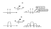
相互変調歪は、図11(A)に示すように通常2波の信号が増幅器AMPなどの能動素子に入ると、2波の周波数間隔分離れたところに歪信号が発生する現象である。3次相互変調歪であれば周波数f2+(f2−f1)に発生し、5次相互変調歪であれば周波数f2+2(f2−f1)に発生する。同様の原理で、変調波を増幅器AMPに入力した場合、変調波を線スペクトラムの集合と考えると、各線スペクトラムがお互いの相互変調歪みを発生する結果、図11(B)に示すように、変調波の両側に歪信号が発生する。
As described above, according to the configuration example of FIG. 8, even when the number of carriers is doubled, it is possible to cope with the distortion and to remove distortion outside the baseband. However, in this configuration example, in order to prevent the signal from the low frequency side from leaking to the high frequency side and the signal from the high frequency side from leaking to the low frequency side, the
As shown in FIG. 11A, the intermodulation distortion is a phenomenon in which a distortion signal is generated where a frequency interval of two waves is separated when a signal of two waves normally enters an active element such as an amplifier AMP. If it is third-order intermodulation distortion, it occurs at frequency f2 + (f2-f1), and if it is fifth-order intermodulation distortion, it occurs at frequency f2 + 2 (f2-f1). When the modulated wave is input to the amplifier AMP based on the same principle, when the modulated wave is considered as a set of line spectrums, each line spectrum generates mutual mutual modulation distortion. As a result, as shown in FIG. Distortion signals are generated on both sides of the wave.
図5の従来例および図8の構成例に加えて、送信増幅器に複数の信号を入力した時に生じる相互変調を除去する従来技術が提案されている(特許文献1参照)。この従来技術は、電力増幅器の出力信号を第1、第2の歪補償部にフィードバックするループを備え、第1の歪補償部に低域フィルタを介して電力増幅器出力信号の低域成分をフィードバックして低域側に生じる相互変調歪を補償し、第2の歪補償部に高域フィルタを介して電力増幅器出力信号の高域成分をフィードバックして高域側に生じる相互変調歪を補償する。
図5の従来技術は、キャリア数を増大しようとするとDA変換、AD変換のサンプリング周波数Fsの限界が問題になり、該サンプリング周波数の限界により増大できるキャリア数に限界がある。
図8の構成例はアナログバンドパスフィルタに非常に急峻な減衰特性が必要とされる。
また、上記文献に開示されている従来技術は、相互変調歪を除去するものであるが、周波数を増大するための技術ではない。また、この従来技術は、マルチキャリアを低周波側と高周波側の2系統に分け、各系統毎に設けた送信部の送信増幅器出力を直結した時に生じる相互変調歪を除去するものではない。
以上から本発明の目的はAD変換等に必要となるサンプリング周波数の増加を抑えつつキャリア数を増大できる無線通信装置を提供することである。
本発明の別の目的は、急峻な減衰特性を有するバンドパスフィルタを使用しなくてもマルチキャリア数を増大できる無線通信装置を提供することである。
本発明の別の目的は、マルチキャリアを低周波側と高周波側の2系統に分け、各系統毎に設けた送信部の送信増幅器出力を直結した時に生じる相互変調歪を除去できる無線通信装置を提供することである。
In the prior art shown in FIG. 5, when the number of carriers is increased, the limit of the sampling frequency Fs for DA conversion and AD conversion becomes a problem, and the number of carriers that can be increased due to the limit of the sampling frequency is limited.
The configuration example of FIG. 8 requires a very steep attenuation characteristic for the analog bandpass filter.
The prior art disclosed in the above-mentioned document removes intermodulation distortion, but is not a technique for increasing the frequency. Further, this prior art does not remove the intermodulation distortion that occurs when the multicarrier is divided into two systems, the low frequency side and the high frequency side, and the transmission amplifier output of the transmission unit provided for each system is directly connected.
Accordingly, an object of the present invention is to provide a wireless communication apparatus capable of increasing the number of carriers while suppressing an increase in sampling frequency required for AD conversion or the like.
Another object of the present invention is to provide a wireless communication apparatus capable of increasing the number of multicarriers without using a bandpass filter having a steep attenuation characteristic.
Another object of the present invention is to provide a wireless communication apparatus capable of removing intermodulation distortion that occurs when a multicarrier is divided into two systems, a low frequency side and a high frequency side, and a transmission amplifier output of a transmission unit provided for each system is directly connected. Is to provide.
上記課題は本発明によれば、複数のキャリアを低周波側の第1の系統と高周波側の第2の系統に分け、各系統についてそれぞれ、複数のキャリア信号を合成し、合成信号を無線で送信するための処理を行なう無線通信装置において、前記第1の系統及び第2の系統についてそれぞれ送信信号に生じる歪を補償する第1及び第2の歪補償部と、該第1及び第2の歪補償部の出力をそれぞれ増幅する第1及び第2の増幅部と、該第1及び第2の増幅部それぞれの出力を結合してアンテナに入力する結合部と、該結合部で結合された信号を前記第1及び第2の歪補償部にそれぞれフィードバックする第1及び第2のフィードバック部とを備え、前記第1のフィードバック部は前記送信信号に含まれる低周波側のキャリア信号部分を前記第1の歪補償部にフィードバックし、前記第2のフィードバック部は前記送信信号に含まれる高周波側のキャリア信号部分を前記第2の歪補償部にフィードバックする無線通信装置により達成される。 According to the present invention, according to the present invention, a plurality of carriers are divided into a first system on the low frequency side and a second system on the high frequency side, a plurality of carrier signals are synthesized for each system, and the synthesized signal is wirelessly transmitted. In a wireless communication apparatus that performs processing for transmission, first and second distortion compensators for compensating distortion generated in a transmission signal for each of the first system and the second system, and the first and second systems The first and second amplifying units for amplifying the output of the distortion compensating unit, the coupling unit for coupling the outputs of the first and second amplifying units and inputting them to the antenna, and the coupling unit First and second feedback units that feed back signals to the first and second distortion compensation units, respectively, and the first feedback unit converts a low frequency carrier signal portion included in the transmission signal to the first and second distortion compensation units. First distortion compensation Fed back to the second feedback unit is achieved by a radio communication device for feeding back the carrier signal portion of the high-frequency side included in the transmission signal to the second distortion compensation unit.
また、上記課題は本発明によれば、第1の送信帯域用の信号の増幅を行う第1の系統と、該第1の系統より周波数の高い第2の送信帯域用の信号の増幅を行なう第2の系統とを備え、増幅後の第1送信帯域の信号及び第2送信帯域の信号を送信信号として共通のアンテナから送信する無線通信装置において、前記第1の系統に入力される信号に対して前置歪み補償処理を施す第1前置歪み補償部と、前記第2の系統に入力される信号に対して前置歪み補償処理を施す第2前置歪み補償部と、前記第1前置歪み補償部の出力を増幅する第1増幅部と、前記第2前置歪み補償部の出力を増幅する第2増幅部と、前記第1及び第2増幅部それぞれで増幅された信号を結合して得られる送信信号を前記アンテナに入力する結合部と、該結合部で出力される前記送信信号を帰還して得られたフィードバック信号について第1周波数変換を行なって得られた信号に対して設けられ、前記第1の送信帯域用の信号を通過域に持ち、前記第2の送信帯域用の信号を阻止域に持つLPFと、前記結合部で出力される前記送信信号を帰還して得られたフィードバック信号について第2周波数変換を行なって得られた信号に対して設けられ、前記第2の送信帯域用の信号を通過域に持ち、前記第1の送信帯域用の信号を阻止域に持つHPFとを備え、該LPFの出力を前記第1前置歪み補償部に与え、該HPFの出力を前記第2前置歪み補償部に与える無線通信装置により達成される。 In addition, according to the present invention, the above-described problem is performed by a first system for amplifying a signal for the first transmission band, and a signal for the second transmission band having a higher frequency than the first system. A wireless communication apparatus that transmits the amplified first transmission band signal and the second transmission band signal as a transmission signal from a common antenna. A first predistortion compensation unit that performs predistortion processing on the second signal, a second predistortion compensation unit that performs predistortion processing on a signal input to the second system, and the first A first amplification unit that amplifies the output of the predistortion unit, a second amplification unit that amplifies the output of the second predistortion unit, and the signals amplified by the first and second amplification units, respectively. A coupling unit that inputs a transmission signal obtained by coupling to the antenna, and an output from the coupling unit Provided for a signal obtained by performing first frequency conversion on a feedback signal obtained by feeding back the transmission signal, having a signal for the first transmission band in a passband, An LPF having a signal for a transmission band in a stop band, and a signal obtained by performing second frequency conversion on a feedback signal obtained by feeding back the transmission signal output from the coupling unit; An HPF having the signal for the second transmission band in the passband and the signal for the first transmission band in the stopband, and providing the output of the LPF to the first predistortion compensation unit, This is achieved by a wireless communication device that provides the output of the HPF to the second predistortion compensator .
本発明によれば、複数のキャリアを低周波側と高周波側の2系統に分け、各系統毎に設けた送信部の送信増幅器出力を結合(例えば直結)して送信するようにしたから、AD変換等に必要となるサンプリング周波数の増加を第1従来技術のように増大しなくてもキャリア数を増大することができる。
また、本発明によれば、各送信部の最終段を直結して1つのアンテナに入力し、アンテナに入力する送信信号に含まれる低周波側のキャリア信号部分を低周波側の歪補償部にフィードバックし、又、アンテナに入力する送信信号に含まれる高周波側のキャリア信号部分を高周波側の歪補償部にフィードバックするようにし、各歪補償部で低周波及び高周波の歪を除去するようにしたから、急峻な減衰特性を有するバンドパスフィルタを使用しなくてもマルチキャリア数を増大でき、しかも、各系統毎に設けた送信部の送信増幅器出力を直結した時に生じる相互変調歪を除去することができる。
According to the present invention, a plurality of carriers are divided into two systems, the low frequency side and the high frequency side, and the transmission amplifier output of the transmission unit provided for each system is coupled (for example, directly coupled) and transmitted. The number of carriers can be increased without increasing the sampling frequency required for conversion or the like as in the first prior art.
Further, according to the present invention, the final stage of each transmission unit is directly connected to be input to one antenna, and the low-frequency carrier signal portion included in the transmission signal input to the antenna is used as the low-frequency distortion compensation unit. The high frequency side carrier signal portion included in the transmission signal input to the antenna is fed back to the high frequency side distortion compensation unit, and each distortion compensation unit removes low frequency and high frequency distortion. Therefore, it is possible to increase the number of multicarriers without using a bandpass filter having a steep attenuation characteristic, and to eliminate intermodulation distortion that occurs when the transmission amplifier output of the transmitter provided for each system is directly connected. Can do.
複数のキャリアを低周波側と高周波側の2系統に分け、各系統に信号を無線で送信するための処理を行なう送信部と送信信号に生じる歪を補償する歪補償部を設ける。そして、各送信部の送信増幅器の出力線を結合(例えば、ワイヤ結合により直結)して1つのアンテナに入力する。低周波側のフィードバック部は、前記送信信号に含まれる低周波側のキャリア信号部分を低周波側の歪補償部にフィードバックし、該歪補償部は低周波側の相互変調歪を含む歪を補償する。一方、高周波側のフィードバック部は前記送信信号に含まれる高周波側のキャリア信号部分を高周波側の歪補償部にフィードバックし、該歪補償部は高周波側の相互変調歪を含む歪を補償する。 A plurality of carriers are divided into two systems, a low-frequency side and a high-frequency side, and a transmission unit that performs processing for transmitting a signal wirelessly and a distortion compensation unit that compensates for distortion generated in the transmission signal are provided in each system. Then, the output lines of the transmission amplifiers of the transmission units are coupled (for example, directly coupled by wire coupling) and input to one antenna. The feedback unit on the low frequency side feeds back the carrier signal portion on the low frequency side included in the transmission signal to the distortion compensation unit on the low frequency side, and the distortion compensation unit compensates for distortion including intermodulation distortion on the low frequency side. To do. On the other hand, the high frequency side feedback unit feeds back a high frequency side carrier signal portion included in the transmission signal to the high frequency side distortion compensation unit, and the distortion compensation unit compensates for distortion including high frequency side intermodulation distortion.
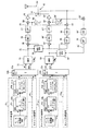
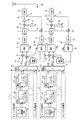
図1は第1実施例の無線通信装置のブロック図、図2は動作説明図であり、(4)〜(6)′は図1の同一番号を付した部分のスペクトラムを示している。なお、図2においてスペクトラム(1)〜(3)は従来例と同一であるため、図示を省略している(図6参照)。
複数の2n個のキャリアはn個づつの低周波側キャリア、高周波側キャリアの2系列に分けられている。低周波側のn個のキャリア毎に設けられた信号処理部511〜51nのべースバンド処理部(BB)51aは、送信すべきデータに対して誤り訂正/検出符号の付加、インタリーブ、多値変調、符号拡散などのべースバンド信号処理を施し、複素のべースバンド信号を出力する。ルートナイキストフィルタは51b、51cはべースバンド処理部51aから入力する複素べースバンド信号の実数部と虚数部にルートナイキストフィルタ処理を施し(図6の(1)参照)、キャリアシフト部51c,51dはべースバンド信号の実数部と虚数部にexp(jωjt)(j=1〜n)を乗算して角周波数ωjのキャリア信号にして出力する(図6の(2)参照)。
FIG. 1 is a block diagram of the wireless communication apparatus according to the first embodiment, FIG. 2 is an operation explanatory diagram, and (4) to (6) ′ indicate the spectrums of the parts denoted by the same numbers in FIG. In FIG. 2, spectrums (1) to (3) are the same as those in the conventional example, and are not shown (see FIG. 6).
The plurality of 2n carriers are divided into two series of n low frequency carriers and high frequency carriers. The baseband processing units (BB) 51a of the
合成部52a,52bは各キャリアの同相分、直交分毎に合成し、合成信号の同相成分Ich及び直交成分Qchを出力し、直交変調部53はキャリア合成信号の周波数帯域幅をW0とするとき、周波数が1.5×W0のローカル信号を用いて該キャリア合成信号に直交変調を施す(図6の(3)参照)。この直交変調により各キャリア周波数は1.5×W0アップした中間周波信号になる。歪補償部54は、送信増幅器60で発生する歪等を補償する歪補償信号を発生し、演算部55は該歪補償信号を直交変調部53の出力信号に加算してDA変換器56に入力する。
DA変換器56は演算部55から入力する歪補償された信号をサンプリング周波数Fsでアナログに変換し、ローパスフィルタ57は不必要な高域成分を除去し(図2の(4)参照)、ミキサ58は、入力信号にローカル発振器59から出力する周波数f0のローカル信号を乗算して周波数(f0+1.5×W0)の無線信号にアップコンバートする。送信増幅器60は周波数アップコンバートされた無線信号を増幅して出力する。
The combining
The
高周波側のn個のキャリア毎に設けられた信号処理部51n+1〜512nのべースバンド処理部(BB)51a、ルートナイキストフィルタ51b、51c、キャリアシフト部51c,51dは低周波側と同様に動作する。ただし、キャリアシフト部51d,51eはべースバンド信号の実数部と虚数部にexp(jωjt)(j=n+1〜2n)を乗算して角周波数ωjのキャリア信号にして出力する。合成部52c,52dは各キャリアの同相分、直交分毎に合成し、合成信号の同相成分Ich及び直交成分Qchを出力し、直交変調部53′はキャリア合成信号の周波数帯域幅をW0とするとき、周波数が1.5×W0のローカル信号を用いて該キャリア合成信号に直交変調を施す。この直交変調により各キャリア周波数は1.5×W0アップした中間周波信号になる。歪補償部54′は、送信増幅器60′で発生する歪等を補償する歪補償信号を発生し、演算部55′は該歪補償信号を直交変調部53′の出力信号に加算してDA変換器56′に入力する。
DA変換器56′は演算部55′から入力する歪補償された信号をサンプリング周波数Fsでアナログに変換し、ローパスフィルタ57′は不必要な高域成分を除去し、ミキサ58′は、入力信号にローカル発振器59′から出力する周波数(f0+W0)のローカル信号を乗算して周波数(f0+2.5×W0)の無線信号にアップコンバートする。送信増幅器60′は周波数アップコンバートされた無線信号を増幅して出力する。
Baseband processor mentioned signal processing unit 51 n + 1 to 51 2n provided for each high-frequency side of the n-number of carriers (BB) 51a, root Nyquist filter 51b, 51c, the
The DA converter 56 'converts the distortion-compensated signal input from the arithmetic unit 55' to analog at the sampling frequency Fs, the low-pass filter 57 'removes unnecessary high-frequency components, and the mixer 58' Is multiplied by a local signal of the frequency (f 0 + W 0 ) output from the
直結部(ワイヤ結合部)61は低周波側送信部の送信増幅器60の出力信号線と高周波側送信部の送信増幅器60′の出力信号線を直結してアンテナを介して送信する(図6の(5)参照)。この直結により、お互いの信号が送信増幅器60,60′に回り込んで、図6の(5)に示すように3次相互変調歪IM1,IM2が生じる。5次の相互変調歪も生じるが図示を省略している。なお、D1,D2は送信増幅器60で発生する歪、D1′,D2′は送信増幅器60′で発生する歪である。
歪D1,D1′および3次相互変調歪IM1を除去するために、方向結合器62は送信信号の一部を抽出し、ミキサ63は入力信号にローカル発振器59から出力するローカル信号を乗算して周波数1.5×W0の中間周波信号にダウンコンバートし、AD変換器64は周波数Fs=6×W0で入力信号をサンプリングしてディジタル変換する。ローパスフィルタ65は図2(6)の点線Aで示すローパス特性を有し、低周波側の主信号と共に歪D1,D1′および3次相互変調歪IM1を歪補償部54に入力する。歪補償部54はLMS適応アルゴリズムを用いてこれら歪みD1,D1′及び3次相互変調歪IM1を除去するための歪補償信号を発生してを低周波側の送信信号に付加する。以上の動作が繰返され、最終的にアンテナ入力信号(図6の(5)参照)から歪みD1,D1′及び3次相互変調歪IM1が除去される。尚、サンプリング周波数FsでAD変換することにより、Fs/2で3次相互変調歪IM2等が折り返すこともあるが、低域フィルタの通過帯域外であるため影響はない。
The direct coupling unit (wire coupling unit) 61 directly connects the output signal line of the
To eliminate distortion D1, D1 'and third-order intermodulation distortion IM 1,
一方、アンテナ入力信号に含まれる歪D2,D2′および3次相互変調歪IM2を補償するために、方向結合器62は送信信号の一部を抽出し、ミキサ63′は入力信号にローカル発振器59′から出力するローカル信号を乗算して周波数1.5×W0の中間周波信号にダウンコンバートし、AD変換器64′は周波数Fs=6×W0で入力信号をサンプリングしてディジタル変換する。ハイパスフィルタ66は図2(6)′の点線Bで示すハイパス特性を有し、高周波側の主信号と共に歪D2,D2′および3次相互変調歪IM2を歪補償部54に入力する。歪補償部54′はLMS適応アルゴリズムを用いてこれら歪みD2,D2′及び3次相互変調歪IM2を除去するための歪補償信号を発生してを高周波側の送信信号に付加する。以上の動作が繰返され、最終的にアンテナ入力信号(図6の(5)参照)から歪みD2,D2′及び3次相互変調歪IM2が除去される。尚、サンプリング周波数FsでAD変換することにより、周波数0で3次相互変調歪IM1が折り返すこともあるが、高域フィルタの通過帯域外であるため影響はない。
以上、第1実施例によれば、サンプリング周波数を増大しなくても、又、急峻な減衰特性を有するバンドパスフィルタを使用しなくてもマルチキャリア数を増大でき、しかも、各系統毎に設けた送信部の送信増幅器出力を直結した時に生じる相互変調歪を除去することができる。
第1実施例では直交復調器53,53′のローカル周波数を1.5W0としたが、1.5W0以上、たとえば、2.5W0とすることができる。ローカル周波数を2.5W0とし、サンプリング周波数Fsを10×W0とすることにより、5次相互変調歪も歪補償部53,53′に入力して歪補償できるようになる。
第1実施例におけるローパスフィルタ、ハイパスフィルタの特性として急峻な特性が必要となるが、アナログと異なりそのような特性を有するディジタルローパスフィルタ、ディジタルハイパスフィルタは容易に設計可能である。
第1実施例では、直結部(ワイヤ結合部)61の出力信号をミキサ63,63′にそれぞれフィードバックしたが、送信増幅器60、60′の出力信号をそれぞれミキサ63,63′にフィードバックするように構成することもできる。
On the other hand, 'in order to compensate for and third-order intermodulation distortion IM 2,
As described above, according to the first embodiment, the number of multicarriers can be increased without increasing the sampling frequency or without using a bandpass filter having a steep attenuation characteristic, and provided for each system. The intermodulation distortion that occurs when the transmission amplifier output of the transmitter is directly connected can be removed.
It was a 1.5 W 0 local frequency of the
Although the steep characteristics are required as the characteristics of the low-pass filter and the high-pass filter in the first embodiment, a digital low-pass filter and a digital high-pass filter having such characteristics can be easily designed unlike analog.
In the first embodiment, the output signal of the direct coupling portion (wire coupling portion) 61 is fed back to the
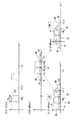
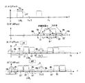
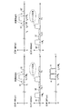
図3は第2実施例の無線通信装置のブロック図、図4は動作説明図であり、(4)〜(6)′は図3の同一番号を付した部分のスペクトラムを示している。尚、(1)〜(3)のスペクトラムは従来例と同一であるため省略している。また、図3において、図1の第1実施例と同一部分には同一符号を付している。
図3において、図1の第1実施例と異なる点は、
(a)演算部55a,55bで歪補償信号が加算された送信信号を直交変調器53,53′に入力する点、
(b) 第1のミキサ63,63′の後段に入力信号の周波数をW0アップする第2のミキサ71,71′、ローカル発振器72を設けている点、
(c) ローカル周波数2.5W0の直交復調器73,73′をそれぞれローパスフィルタ65、ハイパスフィルタ66の後段に設け、その出力信号を歪補償部54,54′にフィードバック入力している点である。
FIG. 3 is a block diagram of the wireless communication apparatus of the second embodiment, FIG. 4 is a diagram for explaining the operation, and (4) to (6) ′ show the spectrums of the parts given the same numbers in FIG. The spectrums (1) to (3) are the same as those in the conventional example, and are omitted. In FIG. 3, the same parts as those of the first embodiment of FIG.
3 differs from the first embodiment of FIG. 1 in that
(a) A point where the transmission signals to which the distortion compensation signals are added by the
(b) The
(c)
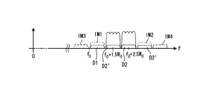
第2実施例において、アンテナ入力信号に含まれる歪D1,D1′および3次、5次相互変調歪IM1、IM3(図4の(5)参照)を除去するために、方向結合器62は送信信号の一部を抽出する。ミキサ63は該抽出された信号にローカル発振器59から出力するローカル信号を乗算して周波数1.5×W0の信号にダウンコンバートし、ミキサ71は該信号の周波数をW0アップして周波数2.5×W0の信号にして出力する。.
AD変換器64は周波数Fs=10×W0で入力信号をサンプリングしてディジタル変換する。ローパスフィルタ65は図4の(6)の点線Aで示すローパス特性を有し、低周波側の主信号と共に歪D1,D1′および3次、5次相互変調歪IM1、IM3を直交復調器73に入力し、直交復調器73はローカル周波数2.5×W0で直交復調して復調信号を歪補償部54に入力する。歪補償部54はLMS適応アルゴリズムを用いて歪みD1,D1′及び3次、5次相互変調歪IM1、IM3を除去するための歪補償信号を発生してを低周波側の送信信号に付加する。以上の動作が繰返され、最終的にアンテナ入力信号(図4の(5)参照)から歪みD1,D1′及び3次、5次相互変調歪IM1、IM3が除去される。尚、サンプリング周波数FsでAD変換することにより、Fs/2で3次相互変調歪IM2が折り返すこともあるが、低域フィルタの通過帯域外であるため影響はない。また、周波数0で5次相互変調歪IM3が折り返すこともあるが、歪補償部54で除去される。
In the second embodiment, in order to remove distortions D1 and D1 ′ and third-order and fifth-order intermodulation distortions IM 1 and IM 3 (see (5) in FIG. 4) included in the antenna input signal, the
The
一方、アンテナ入力信号に含まれる歪D2,D2′および3次、5次相互変調歪IM2、IM4(図4の(5)参照)を補償するために、方向結合器62は送信信号の一部を抽出する。ミキサ63′は該抽出された信号にローカル発振器59から出力するローカル信号を乗算して周波数1.5×W0の信号にダウンコンバートし、ミキサ71′は該信号の周波数をW0アップして周波数2.5×W0の信号にして出力する。.
AD変換器64′は周波数Fs=10×W0で入力信号をサンプリングしてディジタル変換する。ハイパスフィルタ66は図4の(6)′の点線Bで示すハイパス特性を有し、高周波側の主信号と共に歪D2,D2′および3次、5次相互変調歪IM2、IM4を直交復調器73′に入力し、直交復調器73′はローカル周波数2.5×W0で直交復調して復調信号を歪補償部54′に入力する。歪補償部54′はLMS適応アルゴリズムを用いて歪みD2,D2′及び3次、5次相互変調歪IM2、IM4を除去するための歪補償信号を発生してを低周波側の送信信号に付加する。以上の動作が繰返され、最終的にアンテナ入力信号(図4の(5)参照)から歪みD2,D2′及び3次、5次相互変調歪IM2、IM4が除去される。尚、サンプリング周波数FsでAD変換することにより、Fs/2で5次相互変調歪IM4が折り返すこともありうるが、歪補償部54′で除去される。また、周波数0で5次相互変調歪IM3が折り返すこともありうるが、高域フィルタの通過帯域外であるため影響はない。
On the other hand, in order to compensate for distortions D2 and D2 ′ and third-order and fifth-order intermodulation distortions IM 2 and IM 4 (see (5) in FIG. 4) included in the antenna input signal, the
The
以上、第2実施例によれば、サンプリング周波数が第1実施例に比べて高くなるが、第3次相互変調歪に加えて第5次の相互変調歪をも除去することが可能になる。また、急峻な減衰特性を有するバンドパスフィルタを使用しなくてもマルチキャリア数を増大できる。
第2実施例において、低周波側の第1、第2ミキサ63,71によりトータル的に周波数(f0−W0)ダウンし、高周波側の第1、第2ミキサ63′、71′によりトータル的に周波数f0ダウンする。したがって、低周波側の第1、第2ミキサ63,71を1つにまとめて周波数(f0−W0)ダウンするように構成し、また、高周波側の第1、第2ミキサ63′、71′を1つにまとめて周波数f0ダウンするように構成することもできる。
第2実施例では、直結部(ワイヤ結合部)61の出力信号をミキサ63,63′にそれぞれフィードバックしたが、送信増幅器60、60′の出力信号をそれぞれミキサ63,63′にフィードバックするように構成することもできる。
As described above, according to the second embodiment, the sampling frequency is higher than that of the first embodiment, but it is possible to remove the fifth intermodulation distortion in addition to the third intermodulation distortion. In addition, the number of multicarriers can be increased without using a bandpass filter having steep attenuation characteristics.
In the second embodiment, the frequency (f 0 -W 0 ) is totally reduced by the first and
In the second embodiment, the output signal of the direct coupling portion (wire coupling portion) 61 is fed back to the
・(付記)
(付記1)
複数のキャリアを低周波側と高周波側の2系統に分け、各系統に信号を無線で送信するための処理を行なう送信部と送信信号に生じる歪を補償する歪補償部を備えた無線通信装置において、
各送信部の最終段を直結して1つのアンテナに入力する結合部、
該アンテナに入力する送信信号を各系統の歪補償部にそれぞれフィードバックするフィードバック部を備え、
低周波側のフィードバック部は前記送信信号に含まれる低周波側のキャリア信号部分を低周波側の歪補償部にフィードバックし、高周波側のフィードバック部は前記送信信号に含まれる高周波側のキャリア信号部分を高周波側の歪補償部にフィードバックする、
ことを特徴とする無線通信装置。
(付記2) 前記低周波側及び高周波側の送信部はそれぞれ、
複数のキャリア信号を合成する合成部、
合成信号の周波数帯域幅をW0とするとき、周波数が1.5W0以上のローカル信号を用いて該合成信号に直交変調を施す直交変調部、
該直交変調部から出力される信号の周波数を無線周波数にアップコンバートする周波数変換部、
を備えたことを特徴とする付記1記載の無線通信装置。
(付記3)
前記低周波側の周波数変換部が周波数をf0アップした場合には、前記高周波側の周波数変換部は周波数を(f0+W0)アップする、
ことを特徴とする付記2記載の無線通信装置。
(付記4)
低周波側の前記フィードバック部は、
前記低周波側の送信部の周波数変換部で周波数をアップコンバートした分、アンテナ入力信号の周波数をダウンコンバートする周波数変換部、
該周波数変換部出力をディジタルに変換するディジタル変換器、
該ディジタル変換器から出力する信号に含まれる低周波側のキャリア信号部分を通過して低周波側の歪補償部に入力するローパスフィルタ、
を備え、高周波側の前記フィードバック部は、
前記高周波側の送信部の周波数変換部で周波数をアップコンバートした分、アンテナ入力信号の周波数をダウンコンバートする周波数変換部、
該周波数変換部出力をディジタルに変換するディジタル変換器、
該ディジタル変換器から出力する信号に含まれる高周波側のキャリア信号部分を通過して高周波側の歪補償部に入力するハイパスフィルタ、
を備えることを特徴とする付記2又は3記載の無線通信装置。
(付記5)
前記低周波側及び高周波側の送信部はそれぞれ、
複数のキャリア信号を合成する合成部、
合成信号の周波数帯域幅をW0とするとき、前記歪補償部で歪補償された合成信号に周波数が1.5W0のローカル信号を用いて直交変調を施す直交変調部、
直交変調部から出力される信号の周波数を無線周波数にアップコンバートする周波数変換部、
を備え、前記低周波側の周波数変換部は周波数をf0アップし、前記高周波側の周波数変換部は周波数を(f0+W0)アップする、
ことを特徴とする付記1記載の無線通信装置。
(付記6)
低周波側の前記フィードバック部は、
入力信号の周波数をトータル(f0−W0)ダウンする周波数変換部、
該周波数変換部出力をディジタルに変換するディジタル変換器、
該ディジタル変換器から出力する信号に含まれる低周波側のキャリア信号部分を通過するローパスフィルタ、
2.5W0のローカル信号を用いて該ローパスフィルタ出力信号に直交復調を施して低周波側の歪補償部に入力する直交復調部、
を備え、高周波側の前記フィードバック部は、
入力信号の周波数をトータルf0ダウンする周波数変換部、
該第2周波数変換部出力をディジタルに変換するディジタル変換器、
該ディジタル変換器から出力する信号に含まれる高周波側のキャリア信号部分を通過するハイパスフィルタ、
2.5W0のローカル信号を用いて該ハイパスフィルタ出力信号に直交復調を施して高周波側の歪補償部に入力する直交復調部、
を備えることを特徴とする付記5記載の無線通信装置。
(付記7)
前記低周波側のフィードバック部はローパスフィルタを備え、低周波側の主信号と共に低周波側に発生した歪信号を低周波側の歪補償部に入力し、前記高周波側のフィードバック部はハイパスフィルタを備え、高周波側の主信号と共に高周波側に発生した歪信号を高周波側の歪補償部に入力する、
ことを特徴とする付記1記載の無線通信装置。
(付記8)
第1の送信帯域用の信号の増幅を行う第1の系統と、該第1の系統より周波数の高い第2の送信帯域用の信号の増幅を行なう第2の系統とを備え、増幅後の第1送信帯域の信号及び第2送信帯域の信号を送信信号として共通のアンテナから送信する無線通信装置において、
前記第1の系統に入力される信号に対して前置歪み補償処理を施す第1前置歪み補償部と、
前記第2の系統に入力される信号に対して前置歪み補償処理を施す第2前置歪み補償部と、
増幅後の前記送信信号を帰還して得られたフィードバック信号について第1周波数変換を行なって得られた信号に対して設けられ、前記第1の送信帯域用の信号を通過域に持ち、前記第2の送信帯域用の信号を阻止域に持つLPFと、
増幅後の前記送信信号を帰還して得られたフィードバック信号について第2周波数変換を行なって得られた信号に対して設けられ、前記第2の送信帯域用の信号を通過域に持ち、前記第1の送信帯域用の信号を阻止域に持つHPFと、
を備え、該LPFの出力を前記第1前置歪み補償部に与え、該HPFの出力を前記第2前置歪み補償部に与える、
ことを特徴とする無線通信装置。
・ (Appendix)
(Appendix 1)
A wireless communication device comprising a plurality of carriers divided into two systems, a low frequency side and a high frequency side, and a transmission unit that performs processing for wirelessly transmitting a signal to each system and a distortion compensation unit that compensates for distortion generated in the transmission signal In
A coupling unit that directly connects the last stage of each transmission unit and inputs to one antenna,
A feedback unit that feeds back a transmission signal input to the antenna to a distortion compensation unit of each system;
The low frequency side feedback unit feeds back the low frequency side carrier signal portion included in the transmission signal to the low frequency side distortion compensation unit, and the high frequency side feedback unit includes the high frequency side carrier signal portion included in the transmission signal. Is fed back to the high-frequency distortion compensation unit,
A wireless communication apparatus.
(Supplementary Note 2) The low frequency side and high frequency side transmission units are respectively
A combining unit for combining a plurality of carrier signals;
When the frequency bandwidth of the combined signal is W 0 , an orthogonal modulation unit that performs orthogonal modulation on the combined signal using a local signal having a frequency of 1.5 W 0 or more,
A frequency converter that up-converts the frequency of the signal output from the quadrature modulator to a radio frequency;
The wireless communication apparatus according to
(Appendix 3)
When the frequency converter on the low frequency side increases the frequency by f 0 , the frequency converter on the high frequency side increases the frequency by (f 0 + W 0 ).
The wireless communication apparatus according to
(Appendix 4)
The feedback section on the low frequency side is
The frequency converter that down-converts the frequency of the antenna input signal by the amount up-converted by the frequency converter of the transmitter on the low frequency side,
A digital converter for converting the output of the frequency converter to digital;
A low-pass filter that passes through a low-frequency carrier signal portion included in a signal output from the digital converter and inputs the low-frequency side distortion compensation unit;
The high-frequency feedback section is
The frequency converter that down-converts the frequency of the antenna input signal, as the frequency is converted by the frequency converter of the transmitter on the high frequency side,
A digital converter for converting the output of the frequency converter to digital;
A high-pass filter that passes through a high-frequency carrier signal portion included in a signal output from the digital converter and inputs the high-frequency distortion compensation unit;
The wireless communication device according to
(Appendix 5)
Each of the low frequency side and high frequency side transmission units,
A combining unit for combining a plurality of carrier signals;
When the frequency bandwidth of the combined signal is W 0 , an orthogonal modulation unit that performs orthogonal modulation using a local signal having a frequency of 1.5 W 0 on the combined signal that has been distortion-compensated by the distortion compensation unit,
A frequency converter that up-converts the frequency of the signal output from the quadrature modulator to a radio frequency;
The frequency converter on the low frequency side increases the frequency by f 0 , and the frequency converter on the high frequency side increases the frequency by (f 0 + W 0 ),
The wireless communication apparatus according to
(Appendix 6)
The feedback section on the low frequency side is
A frequency converter that reduces the frequency of the input signal by a total (f 0 −W 0 );
A digital converter for converting the output of the frequency converter to digital;
A low-pass filter that passes through a low-frequency carrier signal portion included in a signal output from the digital converter;
A quadrature demodulation unit that performs quadrature demodulation on the low-pass filter output signal using a local signal of 2.5W 0 and inputs the low-pass filter to a low-frequency distortion compensation unit;
The high-frequency feedback section is
A frequency converter that reduces the frequency of the input signal by a total f 0 ;
A digital converter for converting the output of the second frequency converter to digital;
A high-pass filter that passes a high-frequency carrier signal portion included in the signal output from the digital converter;
A quadrature demodulation unit that performs quadrature demodulation on the output signal of the high-pass filter using a local signal of 2.5 W 0 and inputs the high-frequency distortion compensation unit;
The wireless communication apparatus according to
(Appendix 7)
The low-frequency side feedback unit includes a low-pass filter, and a low-frequency side main signal and a distortion signal generated on the low-frequency side are input to the low-frequency side distortion compensation unit, and the high-frequency side feedback unit includes a high-pass filter. Equipped with the main signal on the high frequency side and the distortion signal generated on the high frequency side is input to the distortion compensation unit on the high frequency side,
The wireless communication apparatus according to
(Appendix 8)
A first system for amplifying a signal for a first transmission band; and a second system for amplifying a signal for a second transmission band having a frequency higher than that of the first system. In a wireless communication apparatus that transmits a signal in a first transmission band and a signal in a second transmission band as a transmission signal from a common antenna,
A first predistortion compensation unit that performs predistortion compensation processing on a signal input to the first system;
A second predistortion compensation unit that performs predistortion compensation processing on a signal input to the second system;
Provided for a signal obtained by performing first frequency conversion on a feedback signal obtained by feeding back the amplified transmission signal, having a signal for the first transmission band in a passband, LPF having two transmission band signals in the stop band;
Provided for a signal obtained by performing a second frequency conversion on the feedback signal obtained by feeding back the amplified transmission signal, having a signal for the second transmission band in the passband, An HPF having a signal for one transmission band in the stopband;
Providing the output of the LPF to the first predistortion compensator, and providing the output of the HPF to the second predistortion compensator.
A wireless communication apparatus.
511〜512n 信号処理部
52a〜52d 合成部
53,53′ 直交変調部
54,54′ 歪補償部
55,55′ 演算部
56,56′ DA変換器
57,57′ ローパスフィルタ
58,58′ ミキサ
59 ローカル発振器
60,60′ 送信増幅器
61 直結部(ワイヤ結合部)
62 方向結合器
63,63′ ミキサ
64,64′ AD変換器
65 ローパスフィルタ
66 ハイパスフィルタ
51 1 to 51 2n
62
Claims (5)
前記第1の系統及び第2の系統についてそれぞれ送信信号に生じる歪を補償する第1及び第2の歪補償部と、
該第1及び第2の歪補償部の出力をそれぞれ増幅する第1及び第2の増幅部と、
該第1及び第2の増幅部それぞれの出力を結合してアンテナに入力する結合部と、
該結合部で結合された信号を前記第1及び第2の歪補償部にそれぞれフィードバックする第1及び第2のフィードバック部とを備え、
前記第1のフィードバック部は前記送信信号に含まれる低周波側のキャリア信号部分を前記第1の歪補償部にフィードバックし、前記第2のフィードバック部は前記送信信号に含まれる高周波側のキャリア信号部分を前記第2の歪補償部にフィードバックする、
ことを特徴とする無線通信装置。
Divided plurality of carriers to a second line of the first line and the high-frequency side of the low-frequency side, respectively, for each line, and combining a plurality of carrier signals, the synthesized signal radio communication for performing processing for wirelessly transmitting In the device
First and second distortion compensators for compensating distortion generated in the transmission signal for the first system and the second system, respectively;
First and second amplification units for amplifying the outputs of the first and second distortion compensation units, respectively;
A coupling unit for input to the antenna by combining the respective first and second amplifying unit output,
A first feedback unit and a second feedback unit that feed back the signals combined by the combining unit to the first and second distortion compensation units, respectively.
The first feedback unit feeds back a low-frequency carrier signal portion included in the transmission signal to the first distortion compensation unit, and the second feedback unit transmits a high-frequency carrier signal included in the transmission signal. Feeding back the part to the second distortion compensator;
A wireless communication apparatus.
複数のキャリア信号を合成する合成部、
合成信号の周波数帯域幅をW0とするとき、周波数が1.5W0以上のローカル信号を用いて該合成信号に直交変調を施す直交変調部、
該直交変調部から出力される信号の周波数を無線周波数にアップコンバートする周波数変換部、
前記第1または第2の増幅部、
を備えたことを特徴とする請求項1記載の無線通信装置。 Each of the low frequency side and high frequency side has a transmission unit , the transmission unit,
A combining unit for combining a plurality of carrier signals;
When the frequency bandwidth of the combined signal is W 0 , an orthogonal modulation unit that performs orthogonal modulation on the combined signal using a local signal having a frequency of 1.5 W 0 or more,
A frequency converter that up-converts the frequency of the signal output from the quadrature modulator to a radio frequency;
The first or second amplification section;
The wireless communication apparatus according to claim 1, further comprising:
前記低周波側の送信部の周波数変換部で周波数をアップコンバートした分、アンテナ入力信号の周波数をダウンコンバートする周波数変換部、
該周波数変換部出力をディジタルに変換するディジタル変換器、
該ディジタル変換器から出力する信号に含まれる低周波側のキャリア信号部分を通過して低周波側の歪補償部に入力するローパスフィルタ、
を備え、高周波側の前記第2のフィードバック部は、
前記高周波側の送信部の周波数変換部で周波数をアップコンバートした分、アンテナ入力信号の周波数をダウンコンバートする周波数変換部、
該周波数変換部出力をディジタルに変換するディジタル変換器、
該ディジタル変換器から出力する信号に含まれる高周波側のキャリア信号部分を通過して高周波側の歪補償部に入力するハイパスフィルタ、
を備えることを特徴とする請求項2記載の無線通信装置。 The first feedback section on the low frequency side is
The frequency converter that down-converts the frequency of the antenna input signal by the amount up-converted by the frequency converter of the transmitter on the low frequency side,
A digital converter for converting the output of the frequency converter to digital;
A low-pass filter that passes through a low-frequency carrier signal portion included in a signal output from the digital converter and inputs the low-frequency side distortion compensation unit;
The second feedback unit on the high frequency side includes:
The frequency converter that down-converts the frequency of the antenna input signal, as the frequency is converted by the frequency converter of the transmitter on the high frequency side,
A digital converter for converting the output of the frequency converter to digital;
A high-pass filter that passes through a high-frequency carrier signal portion included in a signal output from the digital converter and inputs the high-frequency distortion compensation unit;
The wireless communication apparatus according to claim 2, further comprising:
複数のキャリア信号を合成する合成部、
合成信号の周波数帯域幅をW0とするとき、前記歪補償部で歪補償された合成信号に周波数が1.5W0のローカル信号を用いて直交変調を施す直交変調部、
直交変調部から出力される信号の周波数を無線周波数にアップコンバートする周波数変換部、
前記第1または第2の増幅部、
を備え、前記低周波側の周波数変換部は周波数をf0アップし、前記高周波側の周波数変換部は周波数を(f0+W0)アップする、
ことを特徴とする請求項1記載の無線通信装置。 Each of the low frequency side and high frequency side has a transmission unit , the transmission unit,
A combining unit for combining a plurality of carrier signals;
When the frequency bandwidth of the combined signal is W 0 , an orthogonal modulation unit that performs orthogonal modulation using a local signal having a frequency of 1.5 W 0 on the combined signal that has been distortion-compensated by the distortion compensation unit,
A frequency converter that up-converts the frequency of the signal output from the quadrature modulator to a radio frequency;
The first or second amplification section;
The frequency converter on the low frequency side increases the frequency by f 0 , and the frequency converter on the high frequency side increases the frequency by (f 0 + W 0 ),
The wireless communication apparatus according to claim 1.
前記第1の系統に入力される信号に対して前置歪み補償処理を施す第1前置歪み補償部と、
前記第2の系統に入力される信号に対して前置歪み補償処理を施す第2前置歪み補償部と、
前記第1前置歪み補償部の出力を増幅する第1増幅部と、
前記第2前置歪み補償部の出力を増幅する第2増幅部と、
前記第1及び第2増幅部それぞれで増幅された信号を結合して得られる送信信号を前記アンテナに入力する結合部と、
該結合部で出力される前記送信信号を帰還して得られたフィードバック信号について第1周波数変換を行なって得られた信号に対して設けられ、前記第1の送信帯域用の信号を通過域に持ち、前記第2の送信帯域用の信号を阻止域に持つLPFと、
前記結合部で出力される前記送信信号を帰還して得られたフィードバック信号について第2周波数変換を行なって得られた信号に対して設けられ、前記第2の送信帯域用の信号を通過域に持ち、前記第1の送信帯域用の信号を阻止域に持つHPFと、
を備え、該LPFの出力を前記第1前置歪み補償部に与え、該HPFの出力を前記第2前置歪み補償部に与える、
ことを特徴とする無線通信装置。 A first system for amplifying a signal for a first transmission band; and a second system for amplifying a signal for a second transmission band having a frequency higher than that of the first system. In a wireless communication apparatus that transmits a signal in a first transmission band and a signal in a second transmission band as a transmission signal from a common antenna,
A first predistortion compensation unit that performs predistortion compensation processing on a signal input to the first system;
A second predistortion compensation unit that performs predistortion compensation processing on a signal input to the second system;
A first amplification unit for amplifying the output of the first predistortion unit;
A second amplification unit for amplifying the output of the second predistortion compensation unit;
A coupling unit that inputs a transmission signal obtained by coupling the signals amplified by the first and second amplification units to the antenna;
Provided for a signal obtained by performing first frequency conversion on a feedback signal obtained by feeding back the transmission signal output from the coupling unit, and the signal for the first transmission band is used as a passband. An LPF having a signal for the second transmission band in a stop band;
Provided with respect to a signal obtained by performing second frequency conversion on the feedback signal obtained by feeding back the transmission signal output from the coupling unit, and passing the second transmission band signal to the passband An HPF having a stop band signal for the first transmission band;
Providing the output of the LPF to the first predistortion compensator, and providing the output of the HPF to the second predistortion compensator.
A wireless communication apparatus.
Priority Applications (3)
| Application Number | Priority Date | Filing Date | Title |
|---|---|---|---|
| JP2004328808A JP4342425B2 (en) | 2004-11-12 | 2004-11-12 | Wireless communication device |
| EP05006096A EP1657814A1 (en) | 2004-11-12 | 2005-03-21 | Radio communication apparatus |
| US11/085,080 US7395033B2 (en) | 2004-11-12 | 2005-03-22 | Radio communication apparatus |
Applications Claiming Priority (1)
| Application Number | Priority Date | Filing Date | Title |
|---|---|---|---|
| JP2004328808A JP4342425B2 (en) | 2004-11-12 | 2004-11-12 | Wireless communication device |
Publications (2)
| Publication Number | Publication Date |
|---|---|
| JP2006140785A JP2006140785A (en) | 2006-06-01 |
| JP4342425B2 true JP4342425B2 (en) | 2009-10-14 |
Family
ID=35929996
Family Applications (1)
| Application Number | Title | Priority Date | Filing Date |
|---|---|---|---|
| JP2004328808A Expired - Fee Related JP4342425B2 (en) | 2004-11-12 | 2004-11-12 | Wireless communication device |
Country Status (3)
| Country | Link |
|---|---|
| US (1) | US7395033B2 (en) |
| EP (1) | EP1657814A1 (en) |
| JP (1) | JP4342425B2 (en) |
Families Citing this family (26)
| Publication number | Priority date | Publication date | Assignee | Title |
|---|---|---|---|---|
| JP4071526B2 (en) * | 2002-04-10 | 2008-04-02 | 松下電器産業株式会社 | Nonlinear distortion compensation apparatus and transmission apparatus |
| US8584239B2 (en) * | 2004-04-01 | 2013-11-12 | Fireeye, Inc. | Virtual machine with dynamic data flow analysis |
| US8010063B2 (en) * | 2007-05-31 | 2011-08-30 | Panasonic Corporation | Signal enhancement in RF transmitters employing non-linear filtering |
| US8160514B2 (en) * | 2008-07-25 | 2012-04-17 | Qualcomm, Incorporated | Transmission noise cancellation |
| EP2161841B1 (en) | 2008-09-08 | 2012-12-12 | Alcatel Lucent | Predistortion of a radio frequency signal |
| GB2465399B (en) | 2008-11-17 | 2015-07-15 | Nujira Ltd | Generation of pre-distortion coefficients |
| US8462881B2 (en) * | 2008-12-31 | 2013-06-11 | Ubidyne, Inc. | Method for digitally predistorting a payload signal and radio station incorporating the method |
| US9397396B2 (en) * | 2009-04-01 | 2016-07-19 | Kathrein-Werke Kg | Radio system and a method for relaying packetized radio signals |
| US8774314B2 (en) * | 2009-06-23 | 2014-07-08 | Qualcomm Incorporated | Transmitter architectures |
| US8731005B2 (en) * | 2009-10-12 | 2014-05-20 | Kathrein-Werke Kg | Absolute timing and Tx power calibration of the Tx path in a distributed system |
| US20110143697A1 (en) * | 2009-12-11 | 2011-06-16 | Qualcomm Incorporated | Separate i and q baseband predistortion in direct conversion transmitters |
| US8880010B2 (en) | 2009-12-30 | 2014-11-04 | Qualcomm Incorporated | Dual-loop transmit noise cancellation |
| US20110235748A1 (en) * | 2010-03-26 | 2011-09-29 | Peter Kenington | Active antenna array having analogue transmitter linearisation and a method for predistortion of radio signals |
| US8599861B2 (en) | 2010-06-03 | 2013-12-03 | Kathrein-Werke Kg | Active antenna array and method for relaying radio signals |
| JP5459158B2 (en) * | 2010-09-21 | 2014-04-02 | 富士通株式会社 | Transmitting apparatus and distortion compensation method |
| JP5679193B2 (en) * | 2011-04-22 | 2015-03-04 | 日本電信電話株式会社 | Transmitter and transceiver |
| DE102012023448A1 (en) * | 2012-11-30 | 2014-06-05 | Rosenberger Hochfrequenztechnik Gmbh & Co. Kg | Method for locating defective locations in an RF signal transmission path |
| US8942314B2 (en) * | 2013-03-14 | 2015-01-27 | Qualcomm Incorporated | Transmit (TX) interference canceller and power detector |
| JP6280697B2 (en) * | 2013-05-27 | 2018-02-14 | サイプレス セミコンダクター コーポレーション | Power amplifier device and compensation method thereof |
| JP2015142325A (en) | 2014-01-30 | 2015-08-03 | 富士通株式会社 | Distortion compensation apparatus and distortion compensation method |
| US9356632B2 (en) * | 2014-10-07 | 2016-05-31 | Qualcomm Incorporated | Intermodulation distortion canceller for use in multi-carrier transmitters |
| CN107210775B (en) * | 2015-01-21 | 2019-09-03 | 株式会社村田制作所 | High frequency power amplifier module and communication device |
| WO2018146741A1 (en) * | 2017-02-08 | 2018-08-16 | 日本電気株式会社 | Transmitter, communication system, control method and programm |
| US10454509B2 (en) | 2018-03-13 | 2019-10-22 | Qualcomm Incorporated | Communication circuit including a transmitter |
| CN111404561B (en) * | 2020-03-10 | 2022-03-29 | Oppo广东移动通信有限公司 | Signal transmitting method based on resource block division and pushing and related product |
| US11973524B2 (en) * | 2021-05-03 | 2024-04-30 | Rockwell Collins, Inc. | Spur dispersing mixer |
Family Cites Families (6)
| Publication number | Priority date | Publication date | Assignee | Title |
|---|---|---|---|---|
| US4675863A (en) * | 1985-03-20 | 1987-06-23 | International Mobile Machines Corp. | Subscriber RF telephone system for providing multiple speech and/or data signals simultaneously over either a single or a plurality of RF channels |
| JP2002064340A (en) | 2000-08-14 | 2002-02-28 | Matsushita Electric Ind Co Ltd | High frequency power amplifier |
| WO2002017586A1 (en) | 2000-08-18 | 2002-02-28 | Nokia Corporation | Multicarrier transmitter circuit arrangement with predistortion linearisation method |
| JP3564382B2 (en) | 2000-10-24 | 2004-09-08 | 松下電器産業株式会社 | Pre-distortion distortion compensation circuit |
| JP3562472B2 (en) | 2001-01-29 | 2004-09-08 | 日本電気株式会社 | Feed forward amplifier |
| US6792252B2 (en) * | 2002-02-06 | 2004-09-14 | Telefonaktiebolaget Lm Ericsson (Publ) | Wideband error amplifier |
-
2004
- 2004-11-12 JP JP2004328808A patent/JP4342425B2/en not_active Expired - Fee Related
-
2005
- 2005-03-21 EP EP05006096A patent/EP1657814A1/en not_active Withdrawn
- 2005-03-22 US US11/085,080 patent/US7395033B2/en not_active Expired - Fee Related
Also Published As
| Publication number | Publication date |
|---|---|
| JP2006140785A (en) | 2006-06-01 |
| US7395033B2 (en) | 2008-07-01 |
| US20060105715A1 (en) | 2006-05-18 |
| EP1657814A1 (en) | 2006-05-17 |
Similar Documents
| Publication | Publication Date | Title |
|---|---|---|
| JP4342425B2 (en) | Wireless communication device | |
| JP5698419B2 (en) | Linearization for a single power amplifier in a multiband transmitter | |
| EP2761742B1 (en) | Systems and methods for digital predistortion in a dual band transmitter | |
| US9252718B2 (en) | Low complexity digital predistortion for concurrent multi-band transmitters | |
| JP5121691B2 (en) | Distortion compensator, transmitter, distortion compensation method | |
| CN100481741C (en) | Amplifier circuit, wireless base station, wireless terminal, and amplifying method | |
| KR100448892B1 (en) | Apparatus and Method for Pre-distortion for Nonlinear Distortion of High Power Amplifier | |
| EP3531565B1 (en) | Tower top device and passive intermodulation cancellation method | |
| US20020105378A1 (en) | Linearisation and modulation device | |
| KR20030025620A (en) | Predistortion type digital linearier with digital if circuit | |
| EP3311497B1 (en) | Radio frequency transmitter | |
| CN100440727C (en) | Distortion compensation device | |
| JP2003524339A (en) | Communication system with predistortion processing | |
| JP5958324B2 (en) | Distortion compensation apparatus and distortion compensation method for power amplification apparatus | |
| JP4686412B2 (en) | Wireless communication device | |
| KR20080065042A (en) | Digital Predistortion Linearizer for Doherty Power Amplifier | |
| EP4391372B1 (en) | Signal amplification circuit and method, and signal transmitter | |
| JP4063612B2 (en) | Transmitter | |
| KR100251385B1 (en) | Apparatus and method for linearizing power amp with adaptive predistortion and modem error compensation | |
| JPH11196140A (en) | Power amplifier | |
| JP2007295331A (en) | Wireless base station equipment | |
| JP3990401B2 (en) | Transmitter | |
| JP4777168B2 (en) | Wireless signal receiver | |
| JP2006279633A (en) | Distortion compensator and its distortion compensation method | |
| KR20060098680A (en) | Analog Predistortion Apparatus and Method for Compensating the Memory Effects of Power Amplifiers in Wireless Communication Systems |
Legal Events
| Date | Code | Title | Description |
|---|---|---|---|
| A621 | Written request for application examination |
Free format text: JAPANESE INTERMEDIATE CODE: A621 Effective date: 20061218 |
|
| A977 | Report on retrieval |
Free format text: JAPANESE INTERMEDIATE CODE: A971007 Effective date: 20090216 |
|
| A131 | Notification of reasons for refusal |
Free format text: JAPANESE INTERMEDIATE CODE: A131 Effective date: 20090407 |
|
| A521 | Request for written amendment filed |
Free format text: JAPANESE INTERMEDIATE CODE: A523 Effective date: 20090602 |
|
| TRDD | Decision of grant or rejection written | ||
| A01 | Written decision to grant a patent or to grant a registration (utility model) |
Free format text: JAPANESE INTERMEDIATE CODE: A01 Effective date: 20090707 |
|
| A01 | Written decision to grant a patent or to grant a registration (utility model) |
Free format text: JAPANESE INTERMEDIATE CODE: A01 |
|
| A61 | First payment of annual fees (during grant procedure) |
Free format text: JAPANESE INTERMEDIATE CODE: A61 Effective date: 20090707 |
|
| FPAY | Renewal fee payment (event date is renewal date of database) |
Free format text: PAYMENT UNTIL: 20120717 Year of fee payment: 3 |
|
| R150 | Certificate of patent or registration of utility model |
Free format text: JAPANESE INTERMEDIATE CODE: R150 |
|
| FPAY | Renewal fee payment (event date is renewal date of database) |
Free format text: PAYMENT UNTIL: 20120717 Year of fee payment: 3 |
|
| FPAY | Renewal fee payment (event date is renewal date of database) |
Free format text: PAYMENT UNTIL: 20130717 Year of fee payment: 4 |
|
| LAPS | Cancellation because of no payment of annual fees |