JP2007295331A - Radio base station device - Google Patents
Radio base station device Download PDFInfo
- Publication number
- JP2007295331A JP2007295331A JP2006121551A JP2006121551A JP2007295331A JP 2007295331 A JP2007295331 A JP 2007295331A JP 2006121551 A JP2006121551 A JP 2006121551A JP 2006121551 A JP2006121551 A JP 2006121551A JP 2007295331 A JP2007295331 A JP 2007295331A
- Authority
- JP
- Japan
- Prior art keywords
- signal
- feedback
- transmission
- distortion compensation
- frequency
- Prior art date
- Legal status (The legal status is an assumption and is not a legal conclusion. Google has not performed a legal analysis and makes no representation as to the accuracy of the status listed.)
- Pending
Links
Images


Abstract
Description
本発明は、移動体通信の無線基地局装置に係り、特に装置構成を簡略化し、高速且つ高精度に電力増幅器の非線形歪を補償することができる無線基地局装置に関する。 The present invention relates to a radio base station apparatus for mobile communication, and more particularly to a radio base station apparatus capable of simplifying the apparatus configuration and compensating for nonlinear distortion of a power amplifier at high speed and with high accuracy.
従来の無線基地局装置における電力増幅器の非線形歪補償方法としては、フィードバック歪補償方式、フィードフォワード歪補償方式、PD(Pre-Distortion)方式がある。
フィードバック方式は、W−CDMA(Wideband Code Division Multiple Access)のように広帯域で使用すると不安定性が増すため、無線基地局での使用には適さない。
フィードフォワード方式は、送信信号中の誤差成分を抽出して副増幅器で増幅し、主増幅器の出力信号から差し引く構成となっているため、回路が複雑になると共に、副増幅器の使用により電力効率が低下するという問題がある。
As a nonlinear distortion compensation method for a power amplifier in a conventional radio base station apparatus, there are a feedback distortion compensation system, a feedforward distortion compensation system, and a PD (Pre-Distortion) system.
The feedback method is not suitable for use in a radio base station because instability increases when used in a wide band like W-CDMA (Wideband Code Division Multiple Access).
The feed-forward method is configured to extract an error component in a transmission signal, amplify it with a sub-amplifier, and subtract it from the output signal of the main amplifier. Therefore, the circuit becomes complicated and power efficiency is improved by using the sub-amplifier. There is a problem of lowering.
最近では、主増幅器で発生する歪の逆特性を予め与えておくため副増幅器が不要なPD方式が用いられ、特に、DPD(Digital Pre-Distortion)方式がよく用いられている。DPD方式では、主増幅器の歪信号自体を用いたフィードバック方式やフィードフォワード方式と比べると、正確な逆特性の歪補償値を生成するのは困難であるが、簡易な構成で、比較的精度の高い逆位相の補償値を生成することができるものである。 Recently, a PD method that does not require a sub-amplifier is used in order to give in advance a reverse characteristic of distortion generated in the main amplifier, and in particular, a DPD (Digital Pre-Distortion) method is often used. In the DPD method, it is difficult to generate a distortion compensation value having an accurate inverse characteristic compared to a feedback method or a feedforward method using the distortion signal itself of the main amplifier, but with a simple configuration and a relatively high accuracy. A high antiphase compensation value can be generated.
そして、DPD方式では、送信出力信号の一部をフィードバック信号として受信して、プレディストータが送信信号との差を検出し、歪補償に用いる参照テーブルの値を最適化する処理を行い、収束した値で参照テーブルを更新し、次の歪補償に用いるようになっている。 In the DPD method, a part of the transmission output signal is received as a feedback signal, the predistorter detects the difference from the transmission signal, performs the process of optimizing the value of the reference table used for distortion compensation, and converges. The reference table is updated with the obtained values and used for the next distortion compensation.
また、これとは別に、デジタル無線通信システムにおいて、通信内容の誤り率を向上させ、通信回線の品質改善を図る方式として、受信ダイバーシティ方式が用いられており、無線基地局装置や端末装置に利用されている。
受信ダイバーシティ方式は、複数の受信機を用意しておき、異なる伝送経路で伝送された信号を受信して、選択あるいは最大比合成等により受信信号の品質を向上させるものである。
Separately, in digital wireless communication systems, the reception diversity method is used as a method for improving the error rate of communication contents and improving the quality of communication lines, and is used for wireless base station devices and terminal devices. Has been.
In the reception diversity method, a plurality of receivers are prepared, signals transmitted through different transmission paths are received, and the quality of the received signal is improved by selection or maximum ratio combining.
尚、受信ダイバーシティ方式を用いた従来の技術としては、平成11年8月31日公開の特開平11−239077号「ディジタル無線機」(出願人:日立電子株式会社、発明者:加藤数衛)がある。
この従来技術は、受信路は、2つのダイバーシティ受信部の内、アンテナ共用器に接続されていない受信専用のアンテナに第1,第2の周波数帯を切り替えるスイッチを備え、基地局を介した通信での受信信号と、基地局を介さずに端末間直接通信での受信信号とを切り替えて受信し、制御部が、基地局を介した受信信号はダイバーシティ受信し、端末間直接通信での受信信号は非ダイバーシティ受信するよう制御するとともに、送信路は切り替えスイッチを備えない構成として、切り替え回路に起因する非線形歪を除去することができるものである(特許文献1参照)。
As a conventional technique using the reception diversity system, Japanese Patent Laid-Open No. 11-239077 “Digital Radio” published on August 31, 1999 (Applicant: Hitachi Electronics Co., Ltd., Inventor: Kazue Kato) There is.
In this prior art, the reception path includes a switch for switching the first and second frequency bands to a reception-dedicated antenna that is not connected to the antenna duplexer among the two diversity receivers, and communicates via the base station. The control unit receives the signal received through the base station with diversity, and receives the signal through the direct communication between the terminals. The signal is controlled to receive non-diversity, and the transmission path is not provided with a changeover switch so that nonlinear distortion caused by the changeover circuit can be removed (see Patent Document 1).
しかしながら、従来のDPD方式では、歪を含む広帯域な送信信号を受信するためのフィードバック回路が別途必要になり、装置コストが増大し、装置小型化の妨げとなるという問題点があった。 However, the conventional DPD method requires a separate feedback circuit for receiving a wideband transmission signal including distortion, increasing the device cost and hindering downsizing of the device.
また、従来のDPD方式では、プレディストータが、送信信号が理想に漸近的に近づくように微調整を繰り返しながら参照テーブル値を収束させる必要があり、参照テーブルの収束処理の処理量が大きく、処理に時間がかかるという問題点があった。 Further, in the conventional DPD method, the predistorter needs to converge the reference table value while repeating fine adjustment so that the transmission signal approaches asymptotically asymptotically, and the processing amount of the convergence process of the reference table is large. There was a problem that processing took time.
特に、フィードバック系を設けるとそれによる新たな歪や、AM−AM特性及びAM−PM特性に対する周波数依存性のメモリ効果が発生し、それらを収束させるために一層処理量が増大して処理時間がかかるという問題点があった。 In particular, when a feedback system is provided, new distortions and frequency-dependent memory effects on the AM-AM characteristics and AM-PM characteristics occur, and the amount of processing increases to converge them, and the processing time increases. There was a problem that it took.
更に、増幅器が周波数特性を有する場合、それらを考慮すると、多くのパラメータや十分な平均化時間が必要であり、高速に処理することができず、ピークが激しく変動する場合には良好な歪補償特性が得られないことがあるという問題点があった。 In addition, when amplifiers have frequency characteristics, many parameters and sufficient averaging time are required, and they cannot be processed at high speed. There was a problem that characteristics could not be obtained.
本発明は上記実状に鑑みて為されたもので、装置の小型化を図り、プレディストータの処理量を軽減し、高速且つ高精度で非線形歪を補償することができる無線基地局装置を提供することを目的とする。 The present invention has been made in view of the above circumstances, and provides a radio base station apparatus that can reduce the size of the apparatus, reduce the processing amount of the predistorter, and compensate for nonlinear distortion at high speed and with high accuracy. The purpose is to do.
上記従来例の問題点を解決するための本発明は、送信信号を増幅する増幅器と、増幅器で発生する非線形歪を補償する歪補償係数を、増幅前の送信信号に乗算すると共に、増幅後の送信信号のフィードバック信号を入力して、フィードバック信号に含まれる歪を高速フーリエ変換により検出し、歪が最小となるよう前記歪補償係数を更新するプレディストータとを備え、無線端末との無線信号の送受信を行う無線基地局装置であって、歪補償係数が乗算された増幅前の送信信号を一定時間遅延する遅延回路を備え、プレディストータが、フィードバック信号と、遅延回路により遅延された信号との差分を高速フーリエ変換することを特徴としている。 The present invention for solving the problems of the above-described conventional example multiplies the transmission signal before amplification by an amplifier that amplifies the transmission signal and a distortion compensation coefficient that compensates for nonlinear distortion generated in the amplifier, and after amplification. A predistorter that inputs a feedback signal of a transmission signal, detects distortion included in the feedback signal by fast Fourier transform, and updates the distortion compensation coefficient so that the distortion is minimized, and a radio signal with a radio terminal A radio base station apparatus that transmits and receives a delay signal that delays a transmission signal before amplification multiplied by a distortion compensation coefficient for a predetermined time, and a predistorter that is delayed by a feedback signal and a delay circuit It is characterized by performing a fast Fourier transform on the difference between the two.
また、本発明は、送信データをデジタル変調する変調部と、変調された送信信号を増幅する増幅器と、送受信用若しくは送信専用の第1のアンテナと、受信専用の第2のアンテナと、増幅器で発生する非線形歪を補償する歪補償係数を、増幅前の送信信号に乗算すると共に、増幅後の送信信号のフィードバック信号を入力して、フィードバック信号に基づいて歪補償係数を更新するプレディストータを備え、無線端末との無線信号の送受信を行う無線基地局装置であって、第2のアンテナが、無線端末からの無線信号を受信すると共に、第1のアンテナから出力された送信信号をフィードバック信号として受信するアンテナであり、第2のアンテナで受信された無線端末からの受信信号とフィードバック信号とを周波数多重信号として同一サンプリング周波数でサンプリングするA/D変換器と、A/D変換器でデジタル変換された周波数多重信号をデジタル直交検波するデジタル直交検波部と、デジタル直交検波された信号を時分割で高速フーリエ変換して、無線端末からの受信信号とフィードバック信号とを分離する高速フーリエ変換部と、分離された両信号を時分割で逆高速フーリエ変換する逆高速フーリエ変換部と、逆高速フーリエ変換された両信号をそれぞれデジタル復調して、無線端末からの受信データとフィードバックデータとを出力する2つの復調部とを備え、プレディストータが、デジタル変調前の送信信号に含まれる既知のパイロットチャネルのデータと、フィードバックデータとの差分に基づいて、歪補償係数を更新するプレディストータであることを特徴としている。 The present invention also includes a modulation unit that digitally modulates transmission data, an amplifier that amplifies the modulated transmission signal, a first antenna dedicated for transmission / reception or transmission, a second antenna dedicated for reception, and an amplifier. A predistorter that multiplies the transmission signal before amplification by a distortion compensation coefficient that compensates for the generated nonlinear distortion, inputs a feedback signal of the transmission signal after amplification, and updates the distortion compensation coefficient based on the feedback signal. A radio base station apparatus for transmitting and receiving radio signals to and from a radio terminal, wherein the second antenna receives a radio signal from the radio terminal and transmits a transmission signal output from the first antenna as a feedback signal The received signal from the wireless terminal received by the second antenna and the feedback signal are the same signal as a frequency multiplexed signal. An A / D converter that samples at the pulling frequency, a digital quadrature detector that digitally detects the frequency multiplexed signal digitally converted by the A / D converter, and fast Fourier transforms the digital quadrature detected signal in a time-division manner. A fast Fourier transform unit that separates a received signal from a wireless terminal and a feedback signal, an inverse fast Fourier transform unit that performs inverse fast Fourier transform on both separated signals in a time-division manner, and both signals that have been subjected to inverse fast Fourier transform Each of which is digitally demodulated, and includes two demodulator units that output received data and feedback data from the wireless terminal, and the predistorter includes data of a known pilot channel included in the transmission signal before digital modulation, A predistorter that updates the distortion compensation coefficient based on the difference from the feedback data It is.
本発明によれば、歪補償係数が乗算された増幅前の送信信号を一定時間遅延する遅延回路を備え、プレディストータが、フィードバック信号と、遅延回路により遅延された信号との差分を高速フーリエ変換して、フィードバック信号に含まれる歪を検出する無線基地局装置としているので、高速フーリエ変換されるデータ量を大幅に削減して処理時間を短縮することができ、プレディストータにおける歪補償係数を更新する処理を高速化することができる効果がある。 According to the present invention, the delay circuit that delays the transmission signal before amplification multiplied by the distortion compensation coefficient for a predetermined time, and the predistorter calculates the difference between the feedback signal and the signal delayed by the delay circuit as a fast Fourier transform. Since it is a radio base station device that detects the distortion included in the feedback signal by converting it, the amount of data subjected to fast Fourier transform can be greatly reduced to shorten the processing time, and the distortion compensation coefficient in the predistorter It is possible to speed up the process of updating the.
また、本発明によれば、第2のアンテナが、無線端末からの無線信号を受信すると共に、第1のアンテナから出力された送信信号をフィードバック信号として受信し、A/D変換器が、第2のアンテナで受信された無線端末からの受信信号とフィードバック信号とを周波数多重信号として同一サンプリング周波数でサンプリングし、デジタル直交検波部が、デジタル変換された周波数多重信号をデジタル直交検波し、高速フーリエ変換部が、デジタル直交検波された信号を時分割で高速フーリエ変換して、無線端末からの受信信号とフィードバック信号とを分離し、逆高速フーリエ変換部が、分離された両信号を時分割で逆高速フーリエ変換し、復調部が、逆高速フーリエ変換された両信号をそれぞれデジタル復調して、無線端末からの受信データとフィードバックデータとを出力し、プレディストータが、デジタル変調前の送信信号に含まれる既知のパイロットチャネルのデータと、フィードバックデータとの差分に基づいて、歪補償係数を更新する無線基地局装置としているので、同一のアンテナで受信された端末からの受信信号とフィードバック信号とを全て共通の回路で処理することにより、フィードバック信号専用の受信回路を不要とし、回路構成を大幅に簡略化して装置コストの低減及び装置の小型化を図ることができると共に、至近距離で発射されたS/N比の高い信号をフィードバック信号として用い、既知のパイロットチャネルの情報との差分に基づいて歪補償係数の最適化処理を行うことにより、プレディストータにおける歪補償係数の最適化の処理を高精度且つ高速に行うことができる効果がある。
According to the present invention, the second antenna receives a radio signal from the radio terminal, receives a transmission signal output from the first antenna as a feedback signal, and the A / D converter The received signal from the wireless terminal received by the
本発明の実施の形態について図面を参照しながら説明する。
本発明の実施の形態に係る無線基地局装置は、歪成分を検出するFFT(Fast Fourier Transform;高速フーリエ変換)部の前段に、A/D変換後の歪補償用の送信フィードバック信号から、フィードバック時間分遅延した送信信号を減算する減算器を設け、送信フィードバック信号と送信信号との差分についてFFTを行って参照テーブルの更新を行うものであり、FFT部における演算量を低減し、処理を高速化することができるものである。
Embodiments of the present invention will be described with reference to the drawings.
The radio base station apparatus according to the embodiment of the present invention provides feedback from a distortion feedback transmission feedback signal after A / D conversion before the FFT (Fast Fourier Transform) unit that detects distortion components. A subtractor that subtracts the transmission signal delayed by the time is provided, and the reference table is updated by performing FFT on the difference between the transmission feedback signal and the transmission signal, reducing the amount of calculation in the FFT unit and speeding up the processing. It can be made.
また、本発明の実施の形態に係る無線基地局装置は、歪補償用の送信フィードバック信号を、ダイバーシティ受信部の2系統のアンテナの内、受信専用アンテナにおいて受信することにより、フィードバック専用の回路を不要とし、装置を簡略化できるものである。 In addition, the radio base station apparatus according to the embodiment of the present invention receives a transmission feedback signal for distortion compensation at a reception-dedicated antenna among the two antennas of the diversity receiver, thereby providing a circuit dedicated for feedback. It is unnecessary and the apparatus can be simplified.
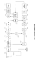
図1は、本発明の第1の実施の形態に係る無線基地局装置(第1の装置)の構成ブロック図である。尚、図1では、第1の装置の送信系とフィードバック系について示しており、受信系については一般的な構成及び動作であるため図示及び説明を省略する。
図1に示すように、第1の装置は、変調部11と、デジタル直交変調部12と、乗算器13と、D/A(Digital-Analog)変換器14と、バンドパスフィルタ
BPF;Band Pass Filter)15と、ミキサ16と、主増幅器(PA;Power Amplifier)17と、方向性結合器18と、バンドパスフィルタ(BPF)19と、アンテナ共用器(Duplex)20と、バンドパスフィルタ(BPF)21と、ミキサ22と、周波数生成部23と、バンドパスフィルタ(BPF)24と、A/D(Analog-Digital)変換器25と、遅延器26と、加算器27と、FFT部28と、平均化部29と、LUT(LUT;Look-Up Table:参照テーブル)収束演算部30と、歪補償テーブル31とから構成されている。
FIG. 1 is a configuration block diagram of a radio base station apparatus (first apparatus) according to the first embodiment of the present invention. Note that FIG. 1 shows the transmission system and feedback system of the first apparatus, and the reception system has a general configuration and operation, and therefore illustration and description thereof are omitted.
As shown in FIG. 1, the first apparatus includes a modulation unit 11, a digital
各構成部分について簡単に説明する。
送信系において、変調部11は、入力データを拡散処理、ゲイン設定、及びハイブリッド位相シフト変調(Hybrid Phase Shift Keying)して各物理チャネル信号を生成し、合成して出力する。
デジタル直交変調部12は変調されたデータをアップサンプルし、ヒルベルトフィルタ等を用いてデジタル直交変調する。
乗算器13は、直交変調された送信データと歪補償テーブル31からの歪補償係数との複素乗算を行う。
Each component will be briefly described.
In the transmission system, the modulation unit 11 performs spreading processing, gain setting, and hybrid phase shift keying on the input data to generate, synthesize, and output the physical channel signals.
The digital
The
D/A変換器14は、デジタル信号をアナログ信号に変換する。
バンドパスフィルタ15は、所望のIF周波数帯を抽出する帯域制限を行う。
ミキサ16は、IF送信信号に周波数生成部23からの入力周波数を乗算して、無線周波数にアップコンバートする。
The D /
The band pass filter 15 performs band limitation for extracting a desired IF frequency band.
The mixer 16 multiplies the IF transmission signal by the input frequency from the
主増幅器17は、送信信号を所定の増幅率で増幅するものであり、増幅の際に非線形歪が発生する。
方向性結合器18は、増幅された送信信号からフィードバック信号を分岐して取り出す。
バンドパスフィルタ19は、送信信号を所望の周波数に帯域制限する。
アンテナ共用器20は、アンテナを送受共用に使用するためのものであり、送信信号をアンテナに出力すると共にアンテナからの受信信号を受信系に出力する。
尚、受信系は、受信信号を復調して受信データを出力する一般的な構成であるので、ここでは説明を省略する。
The
The directional coupler 18 branches and extracts a feedback signal from the amplified transmission signal.
The
The
Since the reception system has a general configuration for demodulating a reception signal and outputting reception data, description thereof is omitted here.
フィードバック系において、バンドパスフィルタ19は、方向性結合器18で分岐されたフィードバック信号を帯域制限するものである。
ミキサ22は、フィードバック信号に周波数生成部23からの周波数を乗算して、IF周波数にダウンコンバートするものである。
In the feedback system, the band-
The mixer 22 multiplies the feedback signal by the frequency from the
周波数生成部23は、ミキサ16とミキサ22へ出力する特定周波数を発振するものである。
バンドパスフィルタ24は、IF周波数のフィードバック信号を更に帯域制限するものである。
A/D変換器24は、アナログ信号をディジタル信号に変換するものである。
The
The
The A /
また、遅延器26は、D/A変換前の送信信号をフィードバック時間分遅延する。
加算器27は、A/D変換器25からのフィードバック信号から遅延された送信信号を減算するものである。
FFT部28は、高速フーリエ変換を行って帯域外成分を検出するものである。
平均化部29は、帯域外成分の電力値を一定時間積分して平均化するものである。
The
The
The
The averaging
歪補償テーブル31は、歪補償係数を記憶するものである。
LUT収束演算部30は、平均化された電力値が最小となるよう、歪補償テーブル31の歪補償値を最適化し、収束値で歪補償テーブル31を更新するものである。
The distortion compensation table 31 stores a distortion compensation coefficient.
The LUT
上記構成の第1の装置における送信系及びフィードバック系の動作について説明する。
第1の装置の送信系では、送信データは、変調部11でデジタル変調され、デジタル直交変調部12で直交変調された後、I,Q信号はそれぞれ乗算器13によって歪補償テーブル31からの歪補償係数との複素乗算が為されて歪補償され、D/A変換器14でアナログ信号に変換される。
また、歪補償された送信データの一部は、遅延器26に入力されて遅延される。
The operation of the transmission system and the feedback system in the first device having the above configuration will be described.
In the transmission system of the first device, transmission data is digitally modulated by the modulation unit 11 and orthogonally modulated by the digital
A part of the transmission data subjected to distortion compensation is input to the
D/A変換された送信信号は、BPF15で帯域制限され、ミキサ16で無線周波数にアップコンバートされ、主増幅器17で所定の増幅率で増幅される。そして、方向性結合器18を介してBPF19で帯域制限され、アンテナ共用器20から送信信号としてアンテナに出力され、送信される。
The D / A converted transmission signal is band-limited by the BPF 15, up-converted to a radio frequency by the mixer 16, and amplified by the
一方、フィードバック系では、方向性結合器18により分岐されたフィードバック信号は、BPF21で帯域制限され、ミキサ22でIF周波数にダウンコンバートされ、BPF24で帯域制限されてA/D変換器25でデジタル信号に変換される。
On the other hand, in the feedback system, the feedback signal branched by the directional coupler 18 is band-limited by the
そして、加算器27で、デジタル信号に変換されたフィードバック信号から、遅延器26においてフィードバック時間分遅延された送信信号を減算することで差分が抽出され、FFT部28によって、増幅によって生じた歪に起因する差分(帯域外成分)のスペクトルが出力される。
The
このように、第1の装置では、フィードバック信号そのものに対してFFTを行うのではなく、送信信号との差分を取ってからFFTを行うようにしているので、データ量を少なくして、FFTの演算量を大幅に低減し、処理の高速化を図ることができるものである。 In this way, the first device does not perform FFT on the feedback signal itself, but performs FFT after taking the difference from the transmission signal. The amount of calculation can be greatly reduced, and the processing speed can be increased.
そして、平均化部29でFFT部28で抽出された帯域外成分の電力値が平均化され、LUT収束演算部30で帯域外成分の電力値が最小となるよう歪補償値が最適化されて、歪補償テーブル31が更新されるようになっている。
Then, the power value of the out-of-band component extracted by the
本発明の第1の実施の形態に係る無線基地局装置によれば、増幅前の送信信号を、フィードバック時間分遅延する遅延器26を設け、加算器27が、送信信号のフィードバック信号から、フィードバック時間分遅延した送信信号を差し引いて、FFT部28が、その差分についてFFTを行って、LUT収束演算部30が、帯域外成分の電力値が最小となるよう歪補償テーブル31を更新するようにしているので、FFT部28に入力されるデータ量を削減してFFTの演算量を大幅に低減することができ、歪補償テーブル31を更新する処理の高速化を図ることができる効果がある。
According to the radio base station apparatus according to the first embodiment of the present invention, the
次に、本発明の第2の実施の形態に係る無線基地局装置(第2の装置)について説明する。
第2の装置は、2系統の受信系を備えたダイバーシティ構成の受信部であり、アンテナ共用器に接続されたアンテナから送信された自身の送信信号を、別の受信専用アンテナで受信して、これをフィードバック信号として用いるものであり、特に端末から受信した信号とフィードバック信号とを周波数多重信号として同一のA/D変換器でA/D変換するものである。これにより、回路構成を簡易にできると共に、至近距離で発射されたSN比の高いフィードバック信号が得られ、これに基づいて歪補償係数を最適化して精度の高い歪補償を行うことができる効果が得られるものである。
Next, a radio base station apparatus (second apparatus) according to the second embodiment of the present invention is described.
The second device is a diversity-structured reception unit having two reception systems, and receives its own transmission signal transmitted from the antenna connected to the antenna duplexer with another antenna dedicated to reception, This is used as a feedback signal. In particular, a signal received from a terminal and a feedback signal are A / D converted by the same A / D converter as a frequency multiplexed signal. As a result, the circuit configuration can be simplified, and a feedback signal with a high S / N ratio emitted at a close distance can be obtained. Based on this, the distortion compensation coefficient can be optimized and highly accurate distortion compensation can be performed. It is obtained.
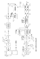
第2の装置の構成について図2を用いて説明する。図2は、第2の装置の構成ブロック図である。尚、図1と同様の部分については、同一の符号を付して説明する。
図2に示すように、第2の装置は、2系統のアンテナを備えており、アンテナ共用器20に接続された0系アンテナ(Ant0)と、受信専用の1系アンテナ(Ant1)とを備え、送信は0系アンテナで行われ、受信は0系と1系の両方で行われる受信ダイバーシティ構成となっている。
The configuration of the second device will be described with reference to FIG. FIG. 2 is a configuration block diagram of the second device. The same parts as those in FIG. 1 will be described with the same reference numerals.
As shown in FIG. 2, the second device includes two antennas, and includes a 0-system antenna (Ant0) connected to the
第2の装置の、0系の送信系は、変調部11と、デジタル直交変調部12と、D/A変換器14と、BPF15と、周波数発振器56と、ミキサ16と、主増幅器17と、バンドパスフィルタ19と、アンテナ共用器(Duplex)20と、0系アンテナ(Ant0)とから構成され、受信専用の1系は、1系アンテナ(Ant1)と、LNA(Low Noise Amplifier;低雑音増幅器)40と、BPF41と、ミキサ42と、BPF44と、A/D変換器45と、デジタル直交検波部46と、FFT部47と、周波数遷移部48と、LPF(Low Pass Filter)49と、IFFT部50と、復調部51と、歪補償補正部52と、歪補償テーブル相関値検出回路53と、複数の周波数発振器54及び55とから構成されている。
尚、0系の受信系については一般的な構成及び動作であるため説明を省略する。
The 0-system transmission system of the second device includes a modulation unit 11, a digital
Since the 0-system receiving system has a general configuration and operation, description thereof is omitted.
0系の送信系は、図1に示した第1の装置における送信系とほぼ同様であるため、ここでは説明を省略するが、変調部11がデジタル直交変調の前段において歪補償テーブル53を参照して位相補償及びレベル補償を行う点等が第1の装置とは異なっている。
また、第2の装置では、歪補償テーブルの更新用として、パイロットチャネル(W−CDMAではCPICH)で予め設定されたビット列を明示的に送信するようになっている。
The 0-system transmission system is almost the same as the transmission system in the first apparatus shown in FIG. 1, and thus the description thereof will be omitted here. However, the modulation unit 11 refers to the distortion compensation table 53 before the digital quadrature modulation. Thus, the first device differs from the first device in that phase compensation and level compensation are performed.
In the second apparatus, a bit string preset in a pilot channel (CPICH in W-CDMA) is explicitly transmitted for updating the distortion compensation table.
1系の構成について具体的に説明する。
1系アンテナは、端末からの通常の受信信号だけでなく、自身の0系アンテナから送信した信号もフィードバック信号として受信するものである。
LNA40は、受信信号を増幅するものである。
BPF41,44は、入力された信号を帯域制限するものである。ここでは、端末からの受信周波数(1950MHz)と、自己の送信周波数(2014MHz)の帯域とを通過させるフィルタを備えている。
ミキサ42は、受信信号に周波数発振器54からの周波数を乗算して、IF周波数にダウンコンバートするものである。
The configuration of
The 1-system antenna receives not only a normal reception signal from the terminal but also a signal transmitted from its own 0-system antenna as a feedback signal.
The
The
The mixer 42 multiplies the received signal by the frequency from the
A/D変換器45は、周波数発振器55からのクロック(例えば、チップレートの16倍である61.44MHz)に基づいて、受信信号をアンダーサンプリングするものである。
デジタル直交検波部46は、受信デジタル信号を、所定の周波数でデジタル直交検波するものである。第2の装置の特徴として、端末からの受信信号とフィードバック信号とを、周波数多重により1台のデジタル直交検波部で同時に直交検波するようになっている。尚、本例では、デジタル直交検波に伴い、サンプルレートが半減するものとする。
The A /
The digital
FFT部47は、第1の装置と同様に、FFT演算を行うものであり、それと共に受信信号とフィードバック信号とを分離するBPFとしての機能を備えたものである。
周波数遷移部48は、フィードバック信号について周波数遷移の処理を行うものである。
LPF49は各周波数成分にフィルタ係数を乗算する等して高周波成分を除去するものである。
IFFT部50は、FFTの逆演算を行うものである。
復調部51は、IFFT変換された信号を、逆拡散してデジタル復調するものである。
Similar to the first device, the
The
The
The
The
このように、第2の装置では、1系アンテナの受信回路の構成を受信信号とフィードバック信号で全て共通としており、装置構成を大幅に簡略化することが可能となる。装置を簡略化するために簡易な方向性結合器でフィードバックさせると、結合量や周波数特性等の再現性が低下するが、第2の装置では、送信系から受信系への正規ルートで受信するので、追加部品が不要となり、安定したフィードバック信号が得られるものである。但し、第1の装置のように方向性結合器を用いて受信系にフィードバック信号を結合させることを妨げるものではない。 As described above, in the second device, the configuration of the reception circuit of the 1-system antenna is all common to the reception signal and the feedback signal, and the device configuration can be greatly simplified. If the feedback is made with a simple directional coupler in order to simplify the device, the reproducibility of the coupling amount, the frequency characteristic, etc. is reduced, but the second device receives the signal via the regular route from the transmission system to the reception system. Therefore, no additional parts are required, and a stable feedback signal can be obtained. However, this does not prevent the feedback signal from being coupled to the reception system using a directional coupler as in the first device.
歪補償補正部52は、復調部51で復調されたデータと、送信したパイロットチャネルの変調前データとを比較して、振幅及び位相を比較し、歪補償テーブル53の歪補償値を更新するものである。歪補償テーブル53は、送信電力に対応付けて歪補償値を格納するものである。歪補償補正部52及び歪補償テーブル53がプレディストータを構成している。尚、ここではプレディストータに歪補償テーブルを備えた構成としているが、テーブルを設けずに、歪補償補正部52が歪補償の制御値を算出して、直接、変調部11に制御値を出力するようにしてもよい。
The distortion
次に、受信信号とフィードバック信号の受信レベルの調整について説明する。
1系においては、端末からの受信信号とフィードバック信号とを多重化して処理するため、両信号の受信レベルを同程度にする必要がある。端末からの受信信号に比べて、フィードバック信号は極めて近い位置で発射された信号であるため、1系アンテナにおける受信レベルが非常に高くなる。そのため、第2の装置では、フィードバック信号の受信レベルを弱めるための構成が設けられている。
Next, adjustment of the reception level of the reception signal and the feedback signal will be described.
In the first system, since the reception signal from the terminal and the feedback signal are multiplexed and processed, it is necessary to make the reception levels of both signals the same level. Compared with the received signal from the terminal, the feedback signal is a signal emitted at a very close position, so that the reception level at the 1-system antenna becomes very high. Therefore, the second device is provided with a configuration for weakening the reception level of the feedback signal.
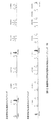
フィードバック信号の受信レベルを弱めるための構成としては、LNA40の前段に新たにフィルタを設けて(図示せず)、フィードバック信号の受信レベルを抑えることが考えられる。図3は、第2の装置の1系アンテナに接続されるフィルタの周波数特性を示す概略説明図である。
As a configuration for weakening the reception level of the feedback signal, a new filter (not shown) may be provided in front of the
端末からの受信周波数と、フィードバック信号の周波数(つまり、自身の送信周波数)とは異なるため、図3に示すように、1系アンテナに接続されるフィルタは本来の受信信号帯域はあまり減衰せずに通過させ、送信信号帯域は大幅に減衰させてレベルを低減することにより、端末からの受信信号と、フィードバック信号の両信号のレベルを同程度にすることが可能となるものである。
Since the frequency received from the terminal is different from the frequency of the feedback signal (that is, its own transmission frequency), as shown in FIG. 3, the filter connected to the
また、別の構成として、0系アンテナから1系アンテナへの回り込みを適度に妨げるための反射板を設けることも考えられる。図4は、アンテナに反射板を設けた場合の説明図である。
図4に示すように、別の構成では、0系アンテナと1系アンテナとの間に反射板を設け、0系アンテナから1系アンテナに直接電波が到来しにくくするものであり、1系アンテナにおける送信信号帯域の受信レベルが、所望のレベルになるよう、反射板のサイズを調整しておく。
As another configuration, it is also conceivable to provide a reflector for appropriately preventing the wraparound from the 0-system antenna to the 1-system antenna. FIG. 4 is an explanatory diagram when a reflector is provided on the antenna.
As shown in FIG. 4, in another configuration, a reflector is provided between the 0-system antenna and the 1-system antenna to make it difficult for radio waves to arrive directly from the 0-system antenna to the 1-system antenna. The size of the reflection plate is adjusted so that the reception level of the transmission signal band at becomes a desired level.
更に、FFT部47及びIFFT部50によるデジタルAGC(Auto Gain Control)によって、両信号のレベルの微調整を行うことができ、両信号のレベルを同程度にすることが可能となっている。尚、フィルタと反射板とを組み合わせて用いてもよい。
Furthermore, the level of both signals can be finely adjusted by digital AGC (Auto Gain Control) by the
次に、第2の装置の1系における周波数多重信号の受信方法について具体的に説明する。
図2の例では、3GPP(第3世代移動体通信システム標準規格)の仕様に基づくW−CDMA方式に、IF帯アンダーサンプリングを適用している。
3GPPの2GHz帯の周波数では、送信周波数の中心周波数と受信周波数の中心周波数とは190MHz離れている。例えば、送信周波数を2140MHzとすると、受信周波数は1950MHzである。
Next, a method for receiving a frequency multiplexed signal in the first system of the second device will be described in detail.
In the example of FIG. 2, IF band undersampling is applied to the W-CDMA system based on the specification of 3GPP (3rd generation mobile communication system standard).
In the 2 GHz band frequency of 3GPP, the center frequency of the transmission frequency and the center frequency of the reception frequency are 190 MHz apart. For example, if the transmission frequency is 2140 MHz, the reception frequency is 1950 MHz.
1系アンテナでは、1950MHzの受信信号(図では「Rx」と記載)と、フィードバック信号となる2140MHzの送信信号(図では「Tx」)を受信し、BPF41で当該周波数帯域を含む周波数多重信号となる。
そして、ローカルオシレータからの周波数によってミキサ42でダウンコンバートしてIF信号を得、A/D変換器45において、61.44MHzでアンダーサンプリングしてデジタル信号に変換すると、受信信号の中心周波数は7.68MHz、フィードバック信号(図では「DPD」)の中心周波数は13.36MHzとなり、5.68MHzのずれがある。
The
Then, if the IF signal is obtained by down-conversion by the mixer 42 using the frequency from the local oscillator, and the A /
そして、デジタル直交検波部46で、周波数多重信号を受信信号の中心周波数7.68MHzで直交検波すると、受信信号の中心周波数は0MHzとなるが、フィードバック信号の中心周波数は、7.68MHzシフトしても5.68MHzのずれが残っている。
そこで、第2の装置では、このずれをFFT部47の後段の周波数遷移部48によって補正するようにしている。
When the digital
Therefore, in the second device, this shift is corrected by the
例えば、直交検波後の信号をW−CDMAの拡散レート3.84MHzの8倍オーバーサンプリングとして扱う場合(3.84×8=30.72MHz)、4096ポイントのFFTを用いれば、周波数領域での間隔は7.5kHzとなる。フィードバック信号の帯域を757ポイント(5.6775MHz相当)シフトさせてもなお2.5kHzのずれが残ることになる。このずれは、隣接周波数を用いて補正演算をすることによって吸収する。補正は、線形演算でも高次の補正演算でも構わない。 For example, when a signal after quadrature detection is handled as 8 times oversampling of a W-CDMA spreading rate of 3.84 MHz (3.84 × 8 = 30.72 MHz), if a 4096-point FFT is used, an interval in the frequency domain Becomes 7.5 kHz. Even if the band of the feedback signal is shifted by 757 points (corresponding to 5.6775 MHz), a deviation of 2.5 kHz still remains. This shift is absorbed by performing a correction operation using the adjacent frequency. The correction may be a linear calculation or a higher-order correction calculation.
尚、第2の装置では、デジタル直交検波部46は、受信信号とフィードバック信号とを分離せずに処理を行うが、FFT部47以降は時分割処理で受信信号とフィードバック信号それぞれについて処理を行うようになっている。図2において、下側の矢印が受信信号を示し、上側の矢印がフィードバック信号を示している。
あるいは、図2に点線で示したように、13.36MHzを中心に直交検波する第2のデジタル直交検波部46′を別途備えれば、FFT部47も時分割共用になるものの、周波数遷移部48を不要とすることができる。
In the second apparatus, the digital
Alternatively, as shown by the dotted line in FIG. 2, if a second digital
FFT部47では、時間領域から周波数領域への変換を行うので、FFT部47の出力は、受信信号とフィードバック信号とに分離されたものとなり、後段の各処理部分においては時分割で各信号毎に処理が行われる。その際、FFTは多くのサンプルに基づく演算であるため、量子化雑音等の帯域外の信号の抑圧が期待できる。また、有効桁増加によりダイナミックレンジが拡大するので、特願2006−010296のようにFFT処理中にAGC(Auto Gain Control)を行うことも可能である。
Since the
そして、LPF49によって、周波数領域において、受信信号及びフィードバック信号毎に適切なルートナイキストフィルタリング等が施され、高周波成分が除去される。その際、受信系やデジタル直交検波の周波数特性を同時に補正してもよい。また、拡散符号(ロングコード)のフーリエ変換を乗算し、逆拡散を周波数領域で行うことも可能である。あるいは、不要になった高周波側のポイントを削除し、ポイント数を減らしてIFFTを行うことで、デシメーションも同時に行うことができる。このようにFFT処理を行うことによって、様々な信号処理を集中的に行うことができ、結果的に演算量を削減できるものである。
そして、フィードバック信号は復調部51aで、受信信号は復調部51bでそれぞれデジタル復調されて、受信信号からは受信データが抽出され、別の回路に出力される。また、フィードバック信号の復調データは、歪補償補正部52に出力される。
Then, the
The feedback signal is digitally demodulated by the demodulator 51a and the received signal is demodulated by the demodulator 51b, and the received data is extracted from the received signal and output to another circuit. The demodulated data of the feedback signal is output to the distortion
そして、歪補償補正部52で、送信信号の変調前のパイロットチャネル(CPICH)のデータと、復調部51から入力されたフィードバック信号のCPICHの復調データに基づいて、歪補正係数の最適化の処理が行われ、歪補償テーブル53が更新されて次の歪補償に用いられるようになっている。
Then, the distortion
次に、第2の装置におけるIF帯周波数、A/D変換器45のサンプリングクロック及びデジタル直交検波46のクロック周波数の関係について説明する。
第2の装置では、受信信号及びフィードバック信号共にA/D変換器45におけるアンダーサンプリングで検出するので、それぞれの信号のIF帯及びエイリアシング帯が重ならないようにサンプリング周波数と検波周波数を選択しなければならない。また、上述したように、3GPPでは送受信の中心周波数差は190MHzと固定されており、各周波数帯は5MHz(中心周波数±2.5MHz)を確保する必要がある。
Next, the relationship between the IF band frequency, the sampling clock of the A /
In the second apparatus, both the received signal and the feedback signal are detected by undersampling in the A /
これらの周波数に関する条件を満たすよう、IF周波数を決定する。
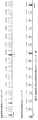
IF周波数及びエイリアシングの例について図5を用いて説明する。図5は、IF周波数とエイリアシングの関係(例1)を示す説明図である。
図5に示すように、エイリアシングは、サンプリング周波数間隔で現れるもの(サンプリング周波数の整数倍の周波数)と、サンプリング周波数の整数倍の周波数の前後に検波周波数分離れて現れるものとがある。これらの内のいずれかをIF帯として選択する。
The IF frequency is determined so as to satisfy the conditions regarding these frequencies.
An example of IF frequency and aliasing will be described with reference to FIG. FIG. 5 is an explanatory diagram showing the relationship (example 1) between the IF frequency and aliasing.
As shown in FIG. 5, there are aliasing that appears at sampling frequency intervals (a frequency that is an integral multiple of the sampling frequency) and that that appears after detection frequency separation before and after a frequency that is an integral multiple of the sampling frequency. One of these is selected as the IF band.
例えば、デジタル直交検波部46で、受信信号を7.68MHzで取り出す場合、A/D変換器45のサンプリングクロックを61.44MHzとすると、IF帯としては69.12MHz、130.56MHz、192.00MHz…のいずれかとなる。
For example, when the digital
仮に、受信ベースバンド信号のIF帯を253.44MHzとすると、送信ベースバンド信号のIF帯周波数は、190MHz差の443.44MHzとなり、図5に示すように、430.08MHzに対して13.36MHzのずれがあるため、5MHzの帯域は確保できる。 If the IF band of the reception baseband signal is 253.44 MHz, the IF band frequency of the transmission baseband signal is 443.44 MHz, which is a difference of 190 MHz, and as shown in FIG. Therefore, the 5 MHz band can be secured.
つまり、サンプリング周波数を61.44MHzとし、デジタル直交検波を7.68MHzで行う場合、受信IF帯とそれに対応する送信IF帯の組合せ(送受信周波数の差が190MHz)を任意に選択しても、各周波数帯は5MHzを確保し、選択したIF帯とは何れのエイリアシングも重ならない、という条件を満たすものであるから、この設定は適切である。 That is, when the sampling frequency is 61.44 MHz and digital quadrature detection is performed at 7.68 MHz, each combination of the reception IF band and the corresponding transmission IF band (the difference between the transmission and reception frequencies is 190 MHz) can be selected. This setting is appropriate because it satisfies the condition that the frequency band is 5 MHz and no aliasing overlaps with the selected IF band.
次に、別の例について図6を用いて説明する。図6は、IF周波数とエイリアシングの関係(例2)を示す説明図である。
デジタル直交検波部46で、受信信号を7.68MHzで検波する場合に、図6に示すように、A/D変換器45のサンプリングクロックを30.72MHzとすると、受信信号のIF帯は、30.72MHzの整数倍の周波数及び、当該整数倍の周波数に対して7.68MHz前後に離れた周波数の中のいずれかとなる。
Next, another example will be described with reference to FIG. FIG. 6 is an explanatory diagram showing a relationship (example 2) between the IF frequency and aliasing.
When the digital
仮に、受信IF帯を238.08MHzとすると、これに対応する送信IF帯は428.08MHzとなるが、この場合、430.08MHzに対して2MHzの隔たりしかなく、5MHzの帯域幅の確保ができない。したがって、この検波周波数とサンプリング周波数の組合せは不適切である。 If the reception IF band is 238.08 MHz, the corresponding transmission IF band is 428.08 MHz. In this case, there is only a 2 MHz separation from 430.08 MHz, and a bandwidth of 5 MHz cannot be secured. . Therefore, this combination of detection frequency and sampling frequency is inappropriate.
次に、更に別の例について図7を用いて説明する。図7は、IF周波数とエイリアシングの関係(例3)を示す説明図である。
図7に示すように、受信信号の検波を9.52MHz、A/D変換器45のサンプリングクロックを30.72MHzとし、受信IF帯を236.24MHzとすると、送信IF帯は426.24MHzとなり、430.08MHzとの差は3.84MHzである。つまり、中心周波数426.24MHz±2.5MHzが430.08MHzと重ならないので、5MHzの帯域は確保でき、この検波周波数とサンプリング周波数の組合せは適切な組合せである。
Next, still another example will be described with reference to FIG. FIG. 7 is an explanatory diagram showing a relationship (example 3) between the IF frequency and aliasing.
As shown in FIG. 7, when the detection of the received signal is 9.52 MHz, the sampling clock of the A /
このように、第2の装置では、受信信号及びフィードバック信号のIF帯及びエイリアシングが重ならないようにA/D変換器45のサンプリングクロック及びデジタル直交検波の検波周波数を設定し、精度の高いフィードバック信号を取り出すことができるようにしている。
As described above, in the second apparatus, the sampling clock of the A /
次に、第2の装置の歪補償の制御について説明する。
第2の装置においては、復調部51から出力される逆拡散済みのパイロットチャネル(CPICH)のデータに基づいて、歪補償補正部52が位相補償量、レベル補償量の補正を行って、歪補償テーブルを更新する。
具体的には、歪補償補正部52は、復調部51からのフィードバック信号の内、予め決められたビット列が入っているCPICHを用いて、送信前のCPICHの情報と、フィードバック信号中のCPICHの情報とを比較し、レベルの低下と位相のずれを検出する。
Next, the distortion compensation control of the second device will be described.
In the second apparatus, the distortion
Specifically, the distortion
フィードバック信号は隣接するアンテナで送信されたものであるため、伝搬による劣化はないものとして扱うことができ、フィードバック信号の受信レベルを測定して、固定値である受信機利得GRXを差し引けば、主増幅器17による振幅歪量を検出することができるものである。
Since the feedback signal is transmitted by the adjacent antenna, it can be treated as having no degradation due to propagation. If the reception level of the feedback signal is measured and the receiver gain GRX which is a fixed value is subtracted, The amount of amplitude distortion by the
また、CPICHの既知のビット列より、位相の回転量つまり複素共役をとった位相補償量も直ちに算出可能である。フィードバック信号は、十分なS/N比が得られるため、平均化時間は従来のDPDに比べて大幅に短くてすむものである。
このように、歪補償値の最適化に既知のパイロットチャネルの情報を用いることにより、歪補償補正部における処理量を削減できるものである。
In addition, the phase rotation amount, that is, the phase compensation amount taking the complex conjugate can be immediately calculated from the known bit string of CPICH. Since a sufficient S / N ratio can be obtained for the feedback signal, the averaging time can be significantly shorter than that of the conventional DPD.
As described above, by using the information of the known pilot channel for optimization of the distortion compensation value, the processing amount in the distortion compensation correction unit can be reduced.
更に、第2の装置では、フィードバック信号のS/N比が良好であるため、復調部51の逆拡散時間(拡散符号乗算後の平均処理間隔)も短くすることができ、処理速度の高速化を図ることができるものである。これにより、従来は追随不可能であった瞬時のピークに対しても即座に補正を行うことができ、精度の高い歪補償を行うことができるものである。
Furthermore, in the second apparatus, since the S / N ratio of the feedback signal is good, the despreading time (average processing interval after multiplication of the spreading code) of the
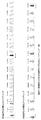
次に、歪補償補正部52における処理について図8を用いて具体的に説明する。図8は、第2の装置の歪補償補正部52の処理を示すフローチャート図である。尚、図8では、周期T毎に行われる処理を示しており、歪補償補正部52が、変調部11に対して直接、歪補償の補正を行う構成について説明する。
Next, the processing in the distortion
図8に示すように、歪補償補正部52は、復調部51からのフィードバック信号の復調データを受信すると、パイロットチャネルCPICHの逆拡散結果c(nT)=a+jbを取得する(100)。ここで、nは自然数であり、Tは1シンボル時間(ショートコード周期)に相当する。
そして、歪補償補正部52は、d(nT)=a2+b2 により、フィードバック信号の振幅d(nT)を算出する(102)。
As shown in FIG. 8, when receiving the demodulated data of the feedback signal from the
Then, the distortion
一方、歪補償補正部52は、送信系の変調部11から、送信信号中のCPICHの複素共役情報C(nT)=(A+jB)を取得し(120)、時刻(nT)における送信CPICHの振幅D(nT)を、D(nT)=A2+B2 により算出する(122)。
On the other hand, the distortion
そして、歪補償補正部52は、処理102と処理120の結果に基づいて、位相補償量P(nT)を、P(nT)=(C(nT)*c(nT)†)/d により算出する(104)。
更に、歪補償補正部52は、処理102及び処理122の結果に基づいて、振幅歪の補正量S(nT)を、S(nT)=D÷d÷GRX=exp(logD−logd−logGRX) により算出する(106)。GRXは、受信系によるレベル低下量であり、既知の定数である。
Then, the distortion
Furthermore, the distortion
そして、歪補償補正部52は、位相補正及び振幅補正を施したパイロットチャネルの情報を変調部11に与える(110)。具体的には、歪補償補正部52は、既知のデータに位相補正を施して C((n+1)T)=C(nT)*P(nT) とし、更に、振幅補正を施して C((n+1)T)=C((n+1)T)×S(nT)を算出して、これを更新後のCPICHとして変調部11に出力する。そして、変調部11では、他の送信データについてもパイロットチャネルと同様に歪補正を施して送信データとするものである。
尚、具体的には、ここで更新された歪補正の情報(位相補償量、振幅補正量)は、時刻(mt+nT+t0)における送信信号に対して適用されるものである。但し、mは自然数でmt≦Tを満たすものであり、tは1サンプル時間、t0は処理100〜110までの処理遅延に相当する。
このようにして、第2の装置の歪補償補正部52の処理が行われるものである。本例では、更新周期がTであるものの、瞬時に更新されるものであり、また、チャネル電力制御周期は10シンボルであるため、大まかな電力変動には十分追従可能である。
Then, the distortion
Specifically, the distortion correction information (phase compensation amount and amplitude correction amount) updated here is applied to the transmission signal at time (mt + nT + t 0 ). However, m is a natural number that satisfies mt ≦ T, t corresponds to one sample time, and t 0 corresponds to a processing delay from processing 100 to 110.
In this way, the processing of the distortion
尚、ここでは、歪補償補正部52が直接変調部11のに対して歪補償の補正を行う場合の処理について説明したが、図2の構成のように、歪補償テーブル53に位相と振幅の歪補償係数を記憶している場合には、処理104で算出された位相補償量と、処理106で算出された振幅歪に基づいて、処理122で算出された電力に対応する歪補償テーブル53の歪補償係数を更新し、変調部11が更新された歪補償テーブル53を参照して次の歪補償を行うようにすればよい。
あるいは、逆拡散を行わず、チップレートより高速なサンプルレート周期で処理100〜110を行うと共に、P(nT)とS(nT)をIIR(Infinite Impulse Response)フィルタにおいて平均化する処理を、処理106の後に行ってもよい。
Here, the processing in the case where the distortion
Alternatively, the
本発明の第2の実施の形態に係る無線基地局装置によれば、アンテナ共用器を備えた送受信用の0系アンテナ(Ant0)と、受信専用の1系アンテナ(Ant1)とを備え、受信ダイバーシティ方式で受信する無線基地局装置であって、0系アンテナから発射された送信信号を1系アンテナでフィードバック信号として受信して、本来の受信信号とフィードバック信号との周波数多重信号をA/D変換器45がアンダーサンプリングし、デジタル直交検波部46が直交検波し、FFT部47が、時分割のFFT処理において検出する帯域を変えることにより受信信号とフィードバック信号とを分離して、IFFT部50が時分割で逆FFT変換して復調器51がデジタル復調して受信データとフィードバックデータを出力し、歪補償補正部52が、送信データ中のパイロットチャネル(CPICH)とフィードバックデータのCPICHとの差分に基づいて、位相補償量と振幅歪補正量を算出して歪補償テーブル53を更新する(又は変調部11に位相補償量と振幅歪補正量を出力し、変調部11が位相補償量と振幅歪補正量を反映させた次の送信データを出力する)ようにしているので、フィードバック信号専用の受信回路が不要となり、回路構成を大幅に簡易にすることができ、装置コストの低減及び装置の小型化を図ることができると共に、至近距離で発射されたS/N比の高い信号をフィードバック信号と既知のパイロットチャネルの情報を用いることにより、平均化時間を短縮し、歪補償補正部52の処理を大幅に低減して、歪補償係数の最適化を高精度且つ高速に行うことができる効果がある。
The radio base station apparatus according to the second embodiment of the present invention includes a transmission / reception 0-system antenna (Ant0) including an antenna duplexer and a reception-only 1-system antenna (Ant1). A radio base station apparatus that receives data by a diversity method, receives a transmission signal emitted from a 0-system antenna as a feedback signal by a 1-system antenna, and converts a frequency-multiplexed signal of the original received signal and the feedback signal into an A / D The
また、第2の無線基地局装置によれば、1系において、アンテナからデジタル直交検波部46までは、本来の受信信号とフィードバック信号とを周波数多重信号として、分離せずに処理し、FFT部47で両信号を分離した後は、共通の回路構成で時分割処理を行うようにしているので、装置の構成を一層簡単にすることができる効果がある。
Further, according to the second radio base station apparatus, in the first system, from the antenna to the digital
更に、第2の無線基地局装置によれば、A/D変換器45におけるサンプリング周波数をチップレートの8倍以上に設定し、分解能も高いもの(例えば16bit以上)を採用し、更にFFTのような大規模フィルタ手段を用いたことで、アナログAGCを用いなくても、レベルの変動する受信信号IF帯と送信信号IF帯とを同時に扱える帯域及びダイナミックレンジを確保することができる。従って、簡易な構成で高いS/N比のフィードバック信号を得ることができ、歪補償の精度を向上させることができる効果がある。
Furthermore, according to the second radio base station apparatus, the sampling frequency in the A /
更にまた、第2の無線基地局装置によれば、1系アンテナに、0系アンテナから送信された送信信号(フィードバック信号)の帯域は大幅に減衰させ、端末から送信された本来の受信信号の帯域はあまり減衰させない特性を備えたフィルタを設けているので、フィードバック信号と受信信号とのレベルを同程度にすることができ、周波数多重信号として不都合なく扱うことができる効果がある。 Furthermore, according to the second radio base station apparatus, the band of the transmission signal (feedback signal) transmitted from the 0-system antenna is greatly attenuated to the 1-system antenna, and the original received signal transmitted from the terminal is Since a filter having a characteristic that does not attenuate the band so much is provided, the levels of the feedback signal and the received signal can be made comparable, and there is an effect that the band can be handled without inconvenience as a frequency multiplexed signal.
次に、本発明の第3の実施の形態に係る無線基地局装置について説明する。
第3の装置は、0系アンテナで送信した信号を1系アンテナでフィードバック信号として受信する点は第2の装置と同様であるが、アナログ信号での処理を受信信号とフィードバック信号とで別々の回路で行い、デジタル直交検波以降のデジタル処理を共通の構成で時分割で行うようにしており、フィードバック信号専用の受信系を設けるのに比べて装置構成を簡易にすることができ、送信信号と受信信号とのアイソレーション特性を良好にできるものである。
Next, a radio base station apparatus according to the third embodiment of the present invention is described.
The third device is similar to the second device in that the signal transmitted by the 0-system antenna is received as a feedback signal by the 1-system antenna, but the processing with the analog signal is performed separately for the received signal and the feedback signal. It is performed by a circuit, and digital processing after digital quadrature detection is performed in a time-sharing manner with a common configuration, and the device configuration can be simplified compared to providing a reception system dedicated to feedback signals, and transmission signals The isolation characteristic from the received signal can be improved.
図9は、本発明の第3の実施の形態に係る無線基地局装置(第3の装置)の構成ブロック図である。尚、図1及び図2と同様の構成を取る部分については同一の符号を用いて説明する。
図9に示すように、第3の装置は、アンテナ共用器20を備えた0系アンテナ(Ant0)と、受信専用の1系アンテナ(Ant1)とを備え、0系の送信系、受信系は何れも図2に示した第2の装置と同じであるため、説明を省略する。
FIG. 9 is a configuration block diagram of a radio base station apparatus (third apparatus) according to the third embodiment of the present invention. In addition, the part which has the same structure as FIG.1 and FIG.2 is demonstrated using the same code | symbol.
As shown in FIG. 9, the third device includes a 0-system antenna (Ant0) having an
1系アンテナは、端末からの本来の受信信号と、自身の0系アンテナから送信されたフィードバック信号とを受信するものである。
第2の装置と異なる点は、受信信号の受信回路として、第2の装置と同様のLNA40と、BPF41と、ミキサ42と、BPF44と、A/D変換器45とを備え、それとは別にフィードバック信号の受信回路として、アッテネータ(ATT)60と、BPF61と、ミキサ62と、BPF64と、A/D変換器65とを備え、更に、受信信号とフィードバック信号とを時分割で切り替えてデジタル直交検波部46に入力するスイッチ66を備えている。
The 1-system antenna receives an original received signal from the terminal and a feedback signal transmitted from its own 0-system antenna.
The difference from the second device is that the received signal reception circuit includes the
上記構成部分の内、受信信号系のBPF41は、受信信号の周波数帯域を通過させるフィルタであり、ここでは1950MHzとしている。LNA40,ミキサ42,BPF44については第2の装置と同様であるため、説明を省略する。
A/D変換器45は、61.44MHzのサンプリングクロックで受信信号をサンプリングして中心周波数が7.68MHzの受信デジタル信号を得るものである。
デジタル直交検波部46は、受信デジタル信号を7.68MHzの直交信号と乗算してデジタル直交検波するものである。
Among the above components, the BPF 41 of the reception signal system is a filter that passes the frequency band of the reception signal, and is 1950 MHz here. Since the
The A /
The digital
また、フィードバック信号系のアッテネータ60は、フィードバック信号の振幅を減衰させて適切な受信レベルとするものである。
BPF61は、フィードバック信号の周波数帯域2140MHzを通過させるフィルタである。
The feedback signal system attenuator 60 attenuates the amplitude of the feedback signal to obtain an appropriate reception level.
The BPF 61 is a filter that passes the frequency band 2140 MHz of the feedback signal.
ミキサ62は、ミキサ42と共通のローカルオシレータからの周波数でフィードバック信号をIF周波数にダウンコンバートするものである。
BPF64は、IF周波数に変換されたフィードバック信号を帯域制限するものであり、ここでは通過帯域の中心周波数を259.12MHzとしている。
The mixer 62 downconverts the feedback signal to the IF frequency at a frequency from a local oscillator common to the mixer 42.
The
A/D変換器65は、サンプリングクロック61.44MHzでアンダーサンプリングして、中心周波数13.36MHzのデジタル信号を得るものである。
デジタル直交検波部46′は、13.36MHzの直交信号で、入力されるフィードバックデジタル信号をデジタル直交検波するものである。
The A / D converter 65 undersamples with a sampling clock 61.44 MHz to obtain a digital signal with a center frequency of 13.36 MHz.
The digital quadrature detection unit 46 'is a quadrature signal of 13.36 MHz and performs digital quadrature detection on the input feedback digital signal.
そして、スイッチ66は、デジタル直交検波部46からの受信デジタル信号と、デジタル直交検波部46′からのフィードバックデジタル信号とを時分割で切り替えて、FFT部47に出力するものである。
FFT部47以降の処理は第2の装置と同様であるため説明は省略する。
The switch 66 switches the received digital signal from the digital
Since the processing after the
第3の装置における1系での受信動作について簡単に説明する。
1系アンテナで受信された受信信号は、LNA40で増幅され、BPF41で帯域制限され、ミキサ42でIF周波数にダウンコンバートされ、更にBPF44で帯域制限されて、A/D変換器45でダウンサンプリングされてデジタル信号に変換され、デジタル直交検波部46で直交検波されて、スイッチ66によって時分割でFFT部47に出力される。
The reception operation in the first system in the third device will be briefly described.
The received signal received by the
一方、1系アンテナで受信されたフィードバック信号は、アッテネータ60でレベルを低減され、BPF61で帯域制限され、ミキサ62でIF周波数にダウンコンバートされ、更にBPF64で帯域制限されて、A/D変換器65で受信信号と共通のサンプリングクロックでデジタル信号に変換され、デジタル直交検波部46′で直交検波されて、スイッチ66によって時分割でFFT部47に出力される。
On the other hand, the level of the feedback signal received by the
入力された受信信号及びフィードバック信号は、FFT部47で、FFT処理を行って受信信号とフィードバック信号とが分離され、フィードバック信号は周波数遷移部48で周波数変換される。
The input received signal and feedback signal are subjected to FFT processing in the
そして、受信信号、フィードバック信号は、それぞれ、LPF49で帯域制限され、IFFT部50で逆FFT変換されて、復調部51で逆拡散されて、受信データとフィードバックデータが出力される。
フィードバックデータは、歪補償補正部52において、第2の装置と同様にパイロットチャネルの変調データとの差分が求められ、これに基づいて位相補償量と振幅歪補正量が算出され、歪補償テーブル53が更新される。そして、送信系の変調部11が、更新された歪補償テーブル53に基づいて次の送信データの歪補償を行うようになっている。
尚、第3の装置の0系送信系及び0系受信系の動作は第2の装置と同様であるため、説明は省略する。
The received signal and the feedback signal are each band-limited by the
As for the feedback data, the distortion
Note that the operations of the 0-system transmission system and the 0-system reception system of the third device are the same as those of the second device, and thus description thereof is omitted.
本発明の第3の実施の形態に係る無線基地局装置では、デジタル直交検波部46以降の構成を、受信信号とフィードバック信号で共通に用いることにより、フィードバック信号用の独立した受信系を設けるのに比べて装置構成を簡略化することができ、且つ、アナログ信号の部分を2系統に分離して周波数多重しない構成としているので、第2の装置に比べて送信信号とフィードバック信号のアイソレーション特性を向上させることができる効果がある。
In the radio base station apparatus according to the third embodiment of the present invention, the configuration after the digital
また、デジタル直交検波部46を周波数調整が可能なものとしてスイッチ66の後に設け、受信信号とフィードバック信号で共用とし、受信信号は7.68MHzで直交検波し、フィードバック信号は13.36MHzで直交検波するようにしてもよい。
Further, the digital
本発明は、装置構成を簡略化し、高速且つ高精度に電力増幅器の非線形歪を補償することができる無線基地局装置全般に適している。受信機を備え、フィードバック系と共用するものであればアンテナ間の結合の利用は必須ではないが、受信ダイバーを行う基地局の他に、AAA(Adaptive Array Antenna)やMIMO(Multiple Input Multiple Output)を利用した無線LANルータ等にも適用できる。 INDUSTRIAL APPLICABILITY The present invention is suitable for all radio base station apparatuses that can simplify the apparatus configuration and can compensate for nonlinear distortion of a power amplifier at high speed and with high accuracy. The use of coupling between antennas is not essential as long as it has a receiver and is shared with the feedback system, but in addition to the base station that performs reception divers, AAA (Adaptive Array Antenna) and MIMO (Multiple Input Multiple Output) It can be applied to a wireless LAN router using
11…変調部、 12…デジタル直交変調部、 13…乗算器、 14…D/A変換部、 15,19,21,24,41,44,61,64…バンドパスフィルタ、 16,22,42,62…ミキサ、 17…主増幅器、 18…方向性結合器、 20…アンテナ共用器、 23…周波数発振器、 25,45,65…A/D変換器、 26…遅延器、 27…加算器、 28…FFT部、 29…平均化部、 30…LUT収束演算部、 31,53…歪補償テーブル、 40…LNA、 46…デジタル直交検波部、 47…FFT部、 48…周波数遷移部、 49…LPF、 50…IFFF部、 51…復調部、 52…歪補償補正部、 60…アッテネータ、 66…スイッチ DESCRIPTION OF SYMBOLS 11 ... Modulation part, 12 ... Digital quadrature modulation part, 13 ... Multiplier, 14 ... D / A conversion part, 15, 19, 21, 24, 41, 44, 61, 64 ... Band pass filter, 16, 22, 42 , 62 ... mixer, 17 ... main amplifier, 18 ... directional coupler, 20 ... antenna duplexer, 23 ... frequency oscillator, 25, 45, 65 ... A / D converter, 26 ... delay device, 27 ... adder, 28 ... FFT unit, 29 ... Averaging unit, 30 ... LUT convergence calculation unit, 31,53 ... Distortion compensation table, 40 ... LNA, 46 ... Digital quadrature detection unit, 47 ... FFT unit, 48 ... Frequency transition unit, 49 ... LPF, 50 ... IFFF section, 51 ... demodulation section, 52 ... distortion compensation correction section, 60 ... attenuator, 66 ... switch
Claims (2)
前記増幅器で発生する非線形歪を補償する歪補償係数を、増幅前の送信信号に乗算すると共に、増幅後の送信信号のフィードバック信号を入力して、前記フィードバック信号に含まれる歪を高速フーリエ変換により検出し、前記歪が最小となるよう前記歪補償係数を更新するプレディストータとを備え、
無線端末との無線信号の送受信を行う無線基地局装置であって、
前記歪補償係数が乗算された増幅前の送信信号を一定時間遅延する遅延回路を備え、
前記プレディストータが、前記フィードバック信号と、前記遅延回路により遅延された信号との差分を高速フーリエ変換することを特徴とする無線基地局装置。 An amplifier for amplifying the transmission signal;
The transmission signal before amplification is multiplied by a distortion compensation coefficient that compensates for nonlinear distortion generated in the amplifier, and a feedback signal of the transmission signal after amplification is input, and distortion included in the feedback signal is fast Fourier transformed. A predistorter that detects and updates the distortion compensation coefficient so that the distortion is minimized,
A radio base station apparatus that transmits and receives radio signals to and from a radio terminal,
A delay circuit that delays the transmission signal before amplification multiplied by the distortion compensation coefficient for a predetermined time;
The radio base station apparatus, wherein the predistorter performs fast Fourier transform on a difference between the feedback signal and the signal delayed by the delay circuit.
前記増幅器で発生する非線形歪を補償する歪補償係数を、増幅前の送信信号に乗算すると共に、増幅後の送信信号のフィードバック信号を入力して、前記フィードバック信号に基づいて前記歪補償係数を更新するプレディストータを備え、
無線端末との無線信号の送受信を行う無線基地局装置であって、
前記第2のアンテナが、無線端末からの無線信号を受信すると共に、前記第1のアンテナから出力された送信信号をフィードバック信号として受信するアンテナであり、
前記第2のアンテナで受信された前記無線端末からの受信信号と前記フィードバック信号とを周波数多重信号として同一サンプリング周波数でサンプリングするA/D変換器と、
前記A/D変換器でデジタル変換された周波数多重信号をデジタル直交検波するデジタル直交検波部と、
前記デジタル直交検波された信号を時分割で高速フーリエ変換して、前記無線端末からの受信信号と前記フィードバック信号とを分離する高速フーリエ変換部と、
前記分離された両信号を時分割で逆高速フーリエ変換する逆高速フーリエ変換部と、
前記逆高速フーリエ変換された両信号をそれぞれデジタル復調して、前記無線端末からの受信データとフィードバックデータとを出力する2つの復調部とを備え、
前記プレディストータが、前記デジタル変調前の送信信号に含まれる既知のパイロットチャネルのデータと、前記フィードバックデータとの差分に基づいて、前記歪補償係数を更新するプレディストータであることを特徴とする無線基地局装置。 A modulation unit that digitally modulates transmission data; an amplifier that amplifies the modulated transmission signal; a first antenna dedicated to transmission / reception or transmission; a second antenna dedicated to reception;
Multiply the transmission signal before amplification by a distortion compensation coefficient that compensates for nonlinear distortion generated in the amplifier, and input the feedback signal of the transmission signal after amplification, and update the distortion compensation coefficient based on the feedback signal With a predistorter
A radio base station apparatus that transmits and receives radio signals to and from a radio terminal,
The second antenna is an antenna that receives a radio signal from a radio terminal and receives a transmission signal output from the first antenna as a feedback signal;
An A / D converter that samples the received signal from the wireless terminal received by the second antenna and the feedback signal at the same sampling frequency as a frequency multiplexed signal;
A digital quadrature detection unit for digital quadrature detection of the frequency multiplexed signal digitally converted by the A / D converter;
Fast Fourier transform of the digital quadrature-detected signal in a time division manner to separate a received signal from the wireless terminal and the feedback signal; and
An inverse fast Fourier transform unit that performs inverse fast Fourier transform on the separated signals in a time-sharing manner;
Two demodulating units for digitally demodulating both the signals subjected to the inverse fast Fourier transform and outputting received data and feedback data from the wireless terminal;
The predistorter is a predistorter that updates the distortion compensation coefficient based on a difference between known pilot channel data included in the transmission signal before digital modulation and the feedback data. A wireless base station device.
Priority Applications (1)
| Application Number | Priority Date | Filing Date | Title |
|---|---|---|---|
| JP2006121551A JP2007295331A (en) | 2006-04-26 | 2006-04-26 | Radio base station device |
Applications Claiming Priority (1)
| Application Number | Priority Date | Filing Date | Title |
|---|---|---|---|
| JP2006121551A JP2007295331A (en) | 2006-04-26 | 2006-04-26 | Radio base station device |
Publications (1)
| Publication Number | Publication Date |
|---|---|
| JP2007295331A true JP2007295331A (en) | 2007-11-08 |
Family
ID=38765496
Family Applications (1)
| Application Number | Title | Priority Date | Filing Date |
|---|---|---|---|
| JP2006121551A Pending JP2007295331A (en) | 2006-04-26 | 2006-04-26 | Radio base station device |
Country Status (1)
| Country | Link |
|---|---|
| JP (1) | JP2007295331A (en) |
Cited By (5)
| Publication number | Priority date | Publication date | Assignee | Title |
|---|---|---|---|---|
| JP2009200840A (en) * | 2008-02-21 | 2009-09-03 | Mitsubishi Electric Corp | Transmitter |
| JP2010232866A (en) * | 2009-03-26 | 2010-10-14 | Mitsubishi Electric Corp | Distortion compensation system |
| WO2011108228A1 (en) * | 2010-03-02 | 2011-09-09 | パナソニック株式会社 | Radio communication device and radio communication method |
| CN101626356B (en) * | 2009-08-11 | 2012-07-11 | 北京天碁科技有限公司 | Multi-input multi-output (MIMO) terminal and radio-frequency emission method thereof |
| JP2017017394A (en) * | 2015-06-26 | 2017-01-19 | 株式会社東芝 | Radio repeater and method |
-
2006
- 2006-04-26 JP JP2006121551A patent/JP2007295331A/en active Pending
Cited By (7)
| Publication number | Priority date | Publication date | Assignee | Title |
|---|---|---|---|---|
| JP2009200840A (en) * | 2008-02-21 | 2009-09-03 | Mitsubishi Electric Corp | Transmitter |
| JP2010232866A (en) * | 2009-03-26 | 2010-10-14 | Mitsubishi Electric Corp | Distortion compensation system |
| CN101626356B (en) * | 2009-08-11 | 2012-07-11 | 北京天碁科技有限公司 | Multi-input multi-output (MIMO) terminal and radio-frequency emission method thereof |
| WO2011108228A1 (en) * | 2010-03-02 | 2011-09-09 | パナソニック株式会社 | Radio communication device and radio communication method |
| US8824975B2 (en) | 2010-03-02 | 2014-09-02 | Panasonic Corporation | Radio communication device and radio communication method |
| JP5632844B2 (en) * | 2010-03-02 | 2014-11-26 | パナソニック株式会社 | Wireless communication apparatus and wireless communication method |
| JP2017017394A (en) * | 2015-06-26 | 2017-01-19 | 株式会社東芝 | Radio repeater and method |
Similar Documents
| Publication | Publication Date | Title |
|---|---|---|
| US7346134B2 (en) | Radio receiver | |
| US10164756B2 (en) | Self-interference cancellation antenna systems and methods | |
| US8498584B2 (en) | Frequency agile duplex filter | |
| US8023587B2 (en) | Device and method for pre-distorting a base-band digital signal | |
| US8805298B2 (en) | Transceiver with compensation for transmit signal leakage and method therefor | |
| US9698836B2 (en) | Systems and methods for mitigation of self-interference in spectrally efficient full duplex communications | |
| US8982995B1 (en) | Communication device and method of multipath compensation for digital predistortion linearization | |
| KR101492381B1 (en) | Linearization for a single power amplifier in a multi-band transmitter | |
| US20030058959A1 (en) | Combined digital adaptive pre-distorter and pre-equalizer system for modems in link hopping radio networks | |
| US20070082617A1 (en) | Transceiver with isolation-filter compensation and method therefor | |
| KR100279948B1 (en) | Apparatus and method for linearized power amplification | |
| JP2003304122A (en) | Non-linear distortion compensating device and transmitter | |
| JP2006148854A (en) | Multicarrier receiver and transmitter with delay correcting function | |
| WO2010034834A1 (en) | Technique for suppressing noise in a transmitter device | |
| KR20010071126A (en) | Distortion correction circuit for direct conversion receiver | |
| JP4686412B2 (en) | Wireless communication device | |
| EP1612933A1 (en) | Distortion compensation device | |
| US20050099230A1 (en) | LMS-based adaptive pre-distortion for enhanced power amplifier efficiency | |
| JP2007295331A (en) | Radio base station device | |
| US8027411B2 (en) | Wireless receiver | |
| CN112368985B (en) | System and method for wireless communication | |
| JP3698996B2 (en) | Receiver in communication system | |
| JP2008098781A (en) | Communication apparatus | |
| JP4391552B2 (en) | Wireless communication device | |
| JP2020027966A (en) | Radio communication device and received signal correcting method |