JP4340903B2 - Steering control device - Google Patents
Steering control device Download PDFInfo
- Publication number
- JP4340903B2 JP4340903B2 JP2004566296A JP2004566296A JP4340903B2 JP 4340903 B2 JP4340903 B2 JP 4340903B2 JP 2004566296 A JP2004566296 A JP 2004566296A JP 2004566296 A JP2004566296 A JP 2004566296A JP 4340903 B2 JP4340903 B2 JP 4340903B2
- Authority
- JP
- Japan
- Prior art keywords
- steering
- control device
- rotation
- angle
- steering control
- Prior art date
- Legal status (The legal status is an assumption and is not a legal conclusion. Google has not performed a legal analysis and makes no representation as to the accuracy of the status listed.)
- Expired - Fee Related
Links
Images


Classifications
-
- B—PERFORMING OPERATIONS; TRANSPORTING
- B62—LAND VEHICLES FOR TRAVELLING OTHERWISE THAN ON RAILS
- B62D—MOTOR VEHICLES; TRAILERS
- B62D5/00—Power-assisted or power-driven steering
- B62D5/001—Mechanical components or aspects of steer-by-wire systems, not otherwise provided for in this maingroup
- B62D5/005—Mechanical components or aspects of steer-by-wire systems, not otherwise provided for in this maingroup means for generating torque on steering wheel or input member, e.g. feedback
- B62D5/006—Mechanical components or aspects of steer-by-wire systems, not otherwise provided for in this maingroup means for generating torque on steering wheel or input member, e.g. feedback power actuated
-
- F—MECHANICAL ENGINEERING; LIGHTING; HEATING; WEAPONS; BLASTING
- F16—ENGINEERING ELEMENTS AND UNITS; GENERAL MEASURES FOR PRODUCING AND MAINTAINING EFFECTIVE FUNCTIONING OF MACHINES OR INSTALLATIONS; THERMAL INSULATION IN GENERAL
- F16H—GEARING
- F16H1/00—Toothed gearings for conveying rotary motion
- F16H1/28—Toothed gearings for conveying rotary motion with gears having orbital motion
- F16H1/32—Toothed gearings for conveying rotary motion with gears having orbital motion in which the central axis of the gearing lies inside the periphery of an orbital gear
- F16H2001/326—Toothed gearings for conveying rotary motion with gears having orbital motion in which the central axis of the gearing lies inside the periphery of an orbital gear comprising a carrier with linear guiding means guiding at least one orbital gear
Abstract
Description
本発明は、電動モータを利用してステアリングホイールの操舵を電気的に制御する操舵制御装置の改良に関する。 The present invention relates to an improvement in a steering control device that electrically controls steering of a steering wheel using an electric motor.
近年、ステアリングホイールに連結される操舵軸と、転舵輪を転舵させる転舵機構とを機械的に分離し、これらの連動制御をSBW(Steer By Wire)制御(以下、SBW制御という)によって電気的に行う操舵制御装置が提案されている。 In recent years, a steering shaft connected to a steering wheel and a steering mechanism that steers the steered wheels are mechanically separated, and these interlocking controls are electrically performed by SBW (Steer By Wire) control (hereinafter referred to as SBW control). A steering control device that performs automatically is proposed.
この操舵制御装置では、ステアリングホイールの操作方向と操舵角を検出して、操作方向に沿った操舵角に見合う転舵角を与え、ステアリングホイールの操作に応じた舵取りを行うようになっている。 In this steering control device, an operation direction and a steering angle of the steering wheel are detected, a steering angle corresponding to the steering angle along the operation direction is given, and steering is performed according to the operation of the steering wheel.
その際、電動モータは、ステアリングホイールの操作量や転舵アクチュエータの転舵力、車両に生じる横方向力やヨーレイトなどに応じて駆動され、操舵力を減速機を介してステアリング軸に伝達するようになっている。 At that time, the electric motor is driven in accordance with the operation amount of the steering wheel, the steering force of the steering actuator, the lateral force generated in the vehicle, the yaw rate, etc., so that the steering force is transmitted to the steering shaft via the reduction gear. It has become.
また、操舵力には、通常の操舵補助力とともに、転舵アクチュエータが最大転舵位置になった場合に、ステアリングホイールの回動を停止させるための操舵反力が含まれる。 Further, the steering force includes a steering reaction force for stopping the rotation of the steering wheel when the steering actuator reaches the maximum steering position, in addition to the normal steering assist force.
ところで、SBW制御では、操舵反力を電動モータによって発生させるので、転舵アクチュエータが最大転舵位置になると、電動モータによって、ステアリングホイールの回動を防止することは困難であった。 By the way, in the SBW control, since the steering reaction force is generated by the electric motor, it is difficult to prevent the steering wheel from rotating by the electric motor when the steering actuator reaches the maximum steering position.
例えばロック状態になると、ドライバーによる操舵トルクに抗した操舵反力を発生させるには、大出力のモータが必要になり、また、モータに大電流が流れるため過熱によりモータの焼損を招来する恐れがあった。さりとて、モータの焼損を防止するため、電流を制限すると、操舵補助用のモータに必要なトルクが得られなくなって、ドライバーの過剰な操舵を制限することができなくなっていた。 For example, in the locked state, a motor with a high output is required to generate a steering reaction force against the steering torque by the driver, and a large current flows through the motor, which may cause the motor to burn out due to overheating. there were. If the current is limited to prevent the motor from burning out, the torque required for the steering assisting motor cannot be obtained, and the driver's excessive steering cannot be limited.
そこで、ステアリングホイールの回動をある一定の許容角度の制限範囲内に規制するために、何らかの機械的な制動手段が必要になっていた。 Therefore, in order to restrict the rotation of the steering wheel within a certain allowable angle limit range, some mechanical braking means has been required.
ちなみに、ステアリングホイールの回動を±180度以下にする場合、回転軸上に設けられる突起と、ハウジングなどの固定部材に設けられる突起とを接触させることにより、ステアリングホイールの回動をある許容回転範囲内で規制することができる。ところが、通常のステアリングホイールの許容回転範囲は、3〜4回転程度であるため、許容回転範囲を±180度以下にすると、ステアリングホイールの回転角に対するタイヤ転舵角が大きくなりすぎてしまう。その結果、車両の挙動が過敏になって、操縦安定性が損なわれるという問題があった。 By the way, when turning the steering wheel to ± 180 degrees or less, the steering wheel can be rotated to some extent by bringing the protrusion provided on the rotating shaft into contact with the protrusion provided on the fixing member such as the housing. It can be regulated within the range. However, since the allowable rotation range of a normal steering wheel is about 3 to 4 rotations, if the allowable rotation range is ± 180 degrees or less, the tire turning angle with respect to the rotation angle of the steering wheel becomes too large. As a result, there is a problem that the behavior of the vehicle becomes sensitive and the steering stability is impaired.
そのため、例えば特開2000−16316号公報に示すように、操舵輪の回転限界角を設定する手段として、操舵軸に設けられる第1突起と、操舵軸ハウジングに設けられる第2突起と、第1突起と係合可能な第3突起および第4突起が設けていて、操舵軸の周りに360度以上にわたって回転可能に支持するようにしたものが開示されている。 Therefore, as shown in, for example, Japanese Patent Laid-Open No. 2000-16316, as means for setting the rotation limit angle of the steering wheel, a first protrusion provided on the steering shaft, a second protrusion provided on the steering shaft housing, A third protrusion and a fourth protrusion that can be engaged with the protrusion are provided, and the protrusion is supported so as to be able to rotate 360 degrees or more around the steering shaft.
本発明の目的は、上記従来とは異なる手段によって、ステアリングホイールの許容回転範囲を±180度以上とし、低出力化および低容量のモータを用いて、コンパクトな機械的操舵角制限機構を提供し、装置の小型化および低コスト化を図ることにある。 An object of the present invention is to provide a compact mechanical steering angle limiting mechanism using a motor with a low output and a low capacity by setting the allowable rotation range of the steering wheel to ± 180 degrees or more by means different from the conventional one. This is to reduce the size and cost of the apparatus.
本発明の上記目的は、ステアリングホイールに連結される操舵軸と、転舵輪を転舵させる転舵機構とを機械的に分離し、ステアリングホイールの操舵角を検出して、前記転舵機構によって操舵角に応じた転舵角で前記転舵輪を回動させるようにした操舵制御装置であって、前記ステアリングホイールの回転に応じてハウジング内を内歯歯車に噛み合いながら公転する外歯歯車で構成されるハイポサイクロイド機構と、前記外歯歯車の自転運動のみを回転ディスクの自転運動として取り出すためのオルダム継手機構と、前記回転ディスクに形成された溝と前記ハウジングから突出する突起との係合による回転規制機構とを備えることにより、達成される。 The object of the present invention is to mechanically separate a steering shaft coupled to a steering wheel and a steering mechanism for turning a steered wheel, detect a steering angle of the steering wheel, and steer by the steering mechanism. A steering control device configured to rotate the steered wheels at a steered angle according to an angle, and is configured by an external gear that revolves while meshing with an internal gear in the housing according to the rotation of the steering wheel. Rotation by the engagement of a protrusion formed from the housing and a groove formed in the rotating disk, and an Oldham coupling mechanism for taking out only the rotating movement of the external gear as the rotating movement of the rotating disk. This is achieved by providing a regulation mechanism.
また、上記目的は、前記ハイポサイクロイド機構を、前記ステアリングホイールに連結する回転軸に装着された偏芯ディスクの外周に軸受を介して回転自在に設けられた外歯歯車と、ハウジング内に形成された内歯歯車とで構成し、該内歯歯車と前記外歯歯車との噛合によって構成することにより、達成される。 Further, the above object is formed in the housing with an external gear provided rotatably on the outer periphery of an eccentric disk mounted on a rotating shaft connected to the steering wheel via a bearing. This is achieved by configuring the internal gear with an internal gear and engaging the internal gear with the external gear.
また、上記目的は、前記オルダム継手機構を、前記外歯歯車と、前記回転ディスクとともに、該回転ディスクと前記外歯歯車との間に介挿された中継部材とから構成するようにしたことにより、達成される。 Further, the above object is that the Oldham coupling mechanism is constituted by the external gear, the relay disk, and a relay member interposed between the rotary disk and the external gear. Achieved.
また、上記目的は、前記回転規制機構を、前記回転ディスクに形成された溝と、前記減速機のハウジングから突出する突起との係合によって構成することにより、達成される。 The above object is achieved by configuring the rotation restricting mechanism by engagement of a groove formed in the rotating disk and a protrusion protruding from the housing of the speed reducer.
また、上記目的は、前記回転規制機構には、前記回転ディスクに形成された溝と、前記ハウジングから突出する突起との間に弾性部材を配するようにしたことにより、達成される。 Further, the above object is achieved by arranging an elastic member in the rotation restricting mechanism between a groove formed in the rotating disk and a protrusion protruding from the housing.
また、上記目的は、前記ステアリングホイールに連結する操舵軸に、モータの減速機が配されるとともに、該減速機に隣接してトーションバーによって連結された2軸間の相対角度を検出する角度センサと、該角度センサからの検出結果に基づいてトルクを検出するトルクセンサとを備えた角度・トルクセンサが配されていて、該角度・トルクセンサと、前記モータと、前記減速機とによって反力付与機構を構成するようにしたことにより、達成される。 Further, the object is to provide an angle sensor for detecting a relative angle between two shafts connected to a steering shaft connected to the steering wheel and connected to a torsion bar adjacent to the speed reducer. And an angle / torque sensor including a torque sensor for detecting torque based on a detection result from the angle sensor, and a reaction force generated by the angle / torque sensor, the motor, and the speed reducer. This is achieved by configuring the applying mechanism.
また、上記目的は、前記操舵制御装置を、前記減速機の出力軸に着脱自在に配することにより、達成される。 Moreover, the said objective is achieved by arrange | positioning the said steering control apparatus detachably to the output shaft of the said reduction gear.
また、上記目的は、前記減速機の出力軸端に、円錐テーパ面を形成するとともに、軸方向に沿ってスプラインを形成し、該スプラインおよび前記円錐テーパ面に沿って操舵制御装置を嵌挿させ、ネジによって固定するようにしたことにより、達成される。 Further, the above object is to form a conical taper surface at the output shaft end of the speed reducer, and also to form a spline along the axial direction, and to insert the steering control device along the spline and the conical taper surface. This is achieved by fixing with screws.
また、上記目的は、前記回転ディスクに、該回転ディスクの回転角を検出するためのポテンショメータを設けたことにより、達成される。 The above object is achieved by providing a potentiometer for detecting the rotation angle of the rotating disk on the rotating disk.
また、上記目的は、前記ポテンショメータを、前記減速機のハウジングとの間に設けることにより、達成される。 Moreover, the said objective is achieved by providing the said potentiometer between the housings of the said reduction gear.
また、上記目的は、前記ステアリングホイールと前記減速機と間に配され、トーションバーによって連結された2軸の相対角度を検出する角度センサと、該角度センサからの検出結果に基づいてトルクを検出するトルクセンサとを備えたことにより、達成される。 In addition, the object is to detect the torque based on the detection result from the angle sensor that is arranged between the steering wheel and the speed reducer and detects the relative angle of the two axes connected by the torsion bar. This is achieved by providing a torque sensor that performs the above.
また、上記目的は、前記ポテンショメータによる検出結果に基づいて、前記回転規制機構がロック状態であると判定された場合、前記モータの通電を連続定格電流以下に制限するようにしたことにより、達成される。 Further, the above object is achieved by limiting the energization of the motor to a continuous rated current or less when it is determined that the rotation restricting mechanism is locked based on the detection result by the potentiometer. The
以下、図面を参照しながら、本発明の実施形態を説明する。 Hereinafter, embodiments of the present invention will be described with reference to the drawings.
図1は、本発明の第1実施例に係るステアリング系の概略構成を示し、ステアリング軸1の出力端側に、トーションバー2を介して、入力軸3と、略筒状の出力軸4が連結されている。このトーションバー2は、一端がピン5によって入力軸3に固定され、他端が出力軸4に圧入固定されている。
FIG. 1 shows a schematic configuration of a steering system according to a first embodiment of the present invention. An
また、出力軸4の外周に、減速機6が一対の玉軸受7,7によって支持されている。この減速機6は、出力軸4の外周に圧入固定されたウォームホイール8と、該ウォームホイール8に噛合するウォーム9と、該ウォーム9を回転軸10に取り付けたモータ(図示せず)とから構成され、モータの駆動力を減速機6を介して出力軸4に減速して伝達するようになっている。
A reduction gear 6 is supported on the outer periphery of the
また、減速機6のステアリングホイール側(図1左側)には、角度・トルクセンサ11が配されていて、角度・トルクセンサ11は、トーションバー2の外方に配された検出リング11aと、検出リング11bと、該各検出リング11a,11bの回転角を光学的に検出する検出器11cとからなる角度センサと、該角度センサで検出された位相差に基づいてトルクを検出するトルクセンサとから構成される。これにより、角度・トルクセンサ11によってトーションバー2の捩れ角およびトルクを検出し、ステアリングホイールの回転角に応じてモータの駆動によって減速機6を介してトーションバー2の捩りを制御する反力付与機構が構成されている。なお、12は、入力軸3と出力軸4を回転自在に支持するニードル軸受である。
An angle / torque sensor 11 is disposed on the steering wheel side (left side in FIG. 1) of the speed reducer 6, and the angle / torque sensor 11 includes a detection ring 11 a disposed outside the
また、出力軸4は、端部(図1右側)に向かって縮径するテーパ面4aが形成され、さらに端部に向かって複数のスプライン4bが軸方向に延びている。この端部には、図2に示すようなハブ13が嵌め込まれ、ネジ14によって出力軸4に一体に固定されるようになっている。このハブ13は、ハウジング15に設けられた玉軸受16によって回転自在に支持されている。また、ハブ13は、略筒状部17と、該略筒状部17の外周面から半径方向に延びる略円環状の偏芯ディスク18とからなり、該偏芯ディスク18は、出力軸4の軸心から偏芯した状態で取り付けられている。
Further, the
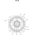
また、偏芯ディスク18の外周には、図3に示すように、外歯歯車19が玉軸受20によって取り付けられ、外歯歯車19は、偏芯ディスク18と同様に、出力軸4に対して偏芯した状態で出力軸4周りを回転するようになっている。一方、ハウジング15内には、外歯歯車19の対向位置に内歯歯車21が設けられていて、該内歯歯車21と外歯歯車19との噛合によって、ハイポサイクロイド機構Aが構成されている。
Further, as shown in FIG. 3, an
また、外歯歯車19の側面には、半径方向に延びる突起22が形成されるとともに、該外歯歯車19のステアリングホイール側(図1左側)には、環状の中継部材23が隣接して配されている。この中継部材23には、端部側(図1右側)に半径方向に延びる溝24が形成されていて、該溝24に外歯歯車19の突起22が半径方向に摺動自在であって、相対回転ができないようになっている。また、中継部材23のステアリングホイール側(図1左側)には、上記溝24と直交する方向の半径方向に突起25が延びている。一方、回転ディスク26の端部側(図1右側)には、半径方向に延びる係合溝27が形成されていて、該係合溝27に中継部材23の突起25が摺動可能であって、相対回転ができないように係合している。さらに、中継部材23のステアリングホイール側(図1左側)には、円環状の回転ディスク26が、玉軸受27によってハブ13に回転自在に支持されている。これにより、中継部材23と回転ディスク26とが一体に回転するようになっていて、外歯歯車19と、中継部材23と、回転ディスク26とによってオルダム継手Bが構成され、外歯歯車19の公転運動を回転ディスク26の自転運動として取り出すようになっている。
A
また、オルダム継手機構Bは、上記玉軸受20,27によって軸方向の所定位置に位置決めされる。また、回転ディスク26は、ハウジング15との間に配された玉軸受28によって軸方向に移動可能になっていて、ハウジング15とハブ13との位置ずれを許容するようになっている。ここで、ハウジング15は、回転ディスク26を支持する玉軸受28の外周側でインローとして組立てられていて、図1E点を境として端部側を取外し可能になっていて、ハウジング15を軸方向に2分割するようになっている。
The Oldham coupling mechanism B is positioned at a predetermined axial position by the
そして、回転ディスク26は、図4に示すように、ステアリングホイール側(図1左側)に、一対の周方向の溝29が形成されている。一方、ハウジング15には、内方に延びる円環状の舌片部30が形成され、該舌片部30から凸部31が端部側(図1右側)に延びている。これにより、凹溝29と凸部31との係合により、回転ディスク26は所定範囲で回転が規制され、回転角規制のストッパとしての役割を担う回転規制機構Cが形成されている。
As shown in FIG. 4, the
なお、上記第1実施例では、回転ディスク26側に凹溝29を設け、ハウジング15側に凸部31を設けたが、回転ディスク26側に凸部を設け、ハウジング15側に凹溝を設けてもよく、上記第1実施例と同一の作用および効果を奏することができる。
In the first embodiment, the
また、内歯歯車21は、単体で成形してハウジング15に取り付けるようにしてもよく、また、ハウジング15と一体に成形してもよい。
Further, the
従って、上記第1実施例では、ステアリングホイールの操舵に応じて回転する回転ディスク26とハウジング15との間で、ステアリングホイールの回転角を規制する回転規制手段Cを備えた。すなわち、回転ディスク26に形成された凹溝29と、ハウジング15から突出する凸部31との係合により、回転ディスク26の許容回転範囲を規制することによって、ステアリングホイールの許容回転範囲を規制するようになっている。そのため、ステアリングホイールに連結する出力軸4上に、偏芯ディスク18を設け、該偏芯ディスク18の外周に軸受20を介して外歯歯車19を支持するとともに、該外歯歯車19とハウジング15に固定された内歯歯車21とでハイポサイクロイド機構Aを構成した。すなわち、ハイポサイクロイド機構Aには、ステアリングホイールの回転が外歯歯車19の公転運動として入力され、外歯歯車19が内歯歯車21に噛み合いながら公転すると、外歯歯車19は、所定の減速比で自転することになる。ここで、所定の減速比とは、Z1/(Z2−Z1)であり、Z1は内歯歯車の歯数で、Z2は外歯歯車の歯数である。例えば、Z1を45とし、Z2を52にすると、減速比は、約6.4になる。
Therefore, in the first embodiment, the rotation restricting means C for restricting the rotation angle of the steering wheel is provided between the
また、回転ディスク26は、中継部材23を介して外歯歯車19でオルダム継手機構Bを構成し、外歯歯車19の公転運動から自転だけを回転ディスク26の回転として取り出すようになっている。これにより、回転ディスク26の凹溝29とハウジング15の凸部31との係合により、回転ディスク26の回転を規制して、ステアリングホイールの回転を規制する回転規制機構Cを構成した。
In addition, the
よって、上記第1実施例では、ハイポサイクロイド機構Aによってステアリングホイールの回転を減速し、オルダム継手機構Bによって外歯歯車19の自転だけを回転ディスク26の回転として取りだし、回転規制機構Cによってステアリングホイールの許容回転範囲を規制する。その結果、機械的な操舵角の規制機構によってステアリングホイールの許容回転範囲を±180度以上にすることができ、装置の小型化および低コスト化を図ることができる。
Therefore, in the first embodiment, the rotation of the steering wheel is decelerated by the hypocycloid mechanism A, only the rotation of the
次に、本発明の第2実施例について説明する。 Next, a second embodiment of the present invention will be described.
図5は、本発明の第2実施例に係るステアリング系の概略構成を示し、上記第1実施例と同一の部材には同一の符号を付して、その説明を省略する。同図において、ステアリングホイールに連結する出力軸4は、端部にハブ13が嵌め込まれている。このハブ13には、一対の玉軸受20,27によってオルダム継手機構Bの位置決めを行うようになっている。
FIG. 5 shows a schematic configuration of a steering system according to the second embodiment of the present invention. The same members as those in the first embodiment are denoted by the same reference numerals, and the description thereof is omitted. In the figure, a
そして、出力軸4に配された玉軸受27には、端部側(図5右側)に付勢する弾性部材である皿ばね41が巻装されていて、この皿ばね41によって、玉軸受27を端部側(図5右側)に押圧して、オルダム継手Bの位置決めに対する作動トルクを確実にするようになっている。
The
一般に、操舵制御装置では、ステアリングホイールから転舵輪(タイヤ)まで機械的に連結されていないので、オルダム継手機構Bに作用する摩擦が小さいと、ステアリングホイールに僅かな力を加えただけでもステアリングホイールが回転し、転舵輪がふらついて、直進安定性が悪化してしまう恐れがあった。そこで、皿ばね41によってオルダム継手機構Bの各係合部に適度な摩擦を与えることにより、操舵制御装置の制御を確実にし、操舵安定性を向上させることができる。 Generally, in the steering control device, since the steering wheel is not mechanically connected to the steered wheels (tires), if the friction acting on the Oldham coupling mechanism B is small, the steering wheel can be applied even if a slight force is applied to the steering wheel. May rotate, and the steered wheels may wobble and the straight running stability may deteriorate. Therefore, by applying appropriate friction to each engaging portion of the Oldham coupling mechanism B by the disc spring 41, the control of the steering control device can be ensured and the steering stability can be improved.
次に、本発明の第3実施例について説明する。 Next, a third embodiment of the present invention will be described.
図6は、本発明の第3実施例に係るステアリング系の概略構成を示し、上記第1実施例と同一の部材には同一の符号を付して、その説明を省略する。同図において、反力付与機構のハウジング51に嵌合孔51aを形成し、該嵌合孔51aに、端部側(図6右側)に延びる突起52を嵌着するようにした。この突起52と、回転ディスク26に所定の回転範囲で周方向に延びる凹溝29とが係合され、突起52と凹溝29との係合によって、回転ディスク26の回転を規制する回転規制機構Cを構成した。
FIG. 6 shows a schematic configuration of a steering system according to the third embodiment of the present invention. The same members as those in the first embodiment are denoted by the same reference numerals, and the description thereof is omitted. In the figure, a fitting hole 51a is formed in the
これにより、第3実施例では、上記第1および第2実施例のように、回転規制機構Cのハウジング15のうち、ステアリングホイール側の端面をなくすことができるとともに、上記第1実施例と同様の作用および効果を奏することができる。
Thus, in the third embodiment, the end surface on the steering wheel side of the
次に、本発明の第4実施例について説明する。 Next, a fourth embodiment of the present invention will be described.
図7は、本発明の第4実施例に係るステアリング系の概略構成を示し、上記第1実施例と同一の部材には同一の符号を付して、その説明を省略する。回転ディスク26は、ステアリングホイール側(図7左側)に、一対の周方向の溝29が形成されるとともに、ハウジング15の舌片部30の凸部31が端部側(図7右側)に延びている。
FIG. 7 shows a schematic configuration of a steering system according to the fourth embodiment of the present invention. The same members as those in the first embodiment are denoted by the same reference numerals, and the description thereof is omitted. The
そして、出力軸4の外側であって、反力付与機構のハウジングと操舵制御装置のハウジング15との間に、回転型ポテンショメータ61を収納するハウジング62が配され、ステアリング軸1の絶対角度の検出センサとして、回転ディスク26の回転量を検出するようにした。なお、63は、ポテンショメータ61に接続するリード線の導入管であり、64は軸受ブッシュで、65は回転ディスク26との係合部である。
A housing 62 that houses the rotary potentiometer 61 is disposed outside the
すなわち、従来の操舵装置のように、タイヤとステアリングホイールが機械的に連結されている場合、直線走行状態を判別して中立位置を補正することができるが、SBW制御の場合、機械的な連結性がないため、タイヤとステアリングホイールの位置がずれてしまい、1回転ずれてしまうと、左右の許容回転角度が不均一となる可能性があった。そこで、第4実施例では、絶対角度の検出センサとしてポテンショメータ61を用いることにより、絶対位置検出が容易に行えるようになった。 That is, when the tire and the steering wheel are mechanically connected as in a conventional steering device, the neutral position can be corrected by determining the straight running state. However, in the case of SBW control, the mechanical connection Therefore, if the positions of the tire and the steering wheel are shifted and the rotation is shifted by one rotation, there is a possibility that the left and right allowable rotation angles are not uniform. Therefore, in the fourth embodiment, the absolute position can be easily detected by using the potentiometer 61 as the absolute angle detection sensor.
なお、角度センサと、トルク検出用の2個の角度センサの合計3個の角度センサを有する構成とし、角度センサの故障を検出する場合、2個ではいずれが異常であるかを判別することができないので、3個設けて検出値の相互比較によって故障を判別する必要があった。 In addition, it is set as the structure which has an angle sensor and two angle sensors in total of two angle sensors for torque detection, and when detecting a failure of an angle sensor, it is possible to discriminate which is abnormal with two. Since it was not possible, it was necessary to provide three and determine the failure by comparing the detected values.
次に、本発明の第5実施例について説明する。 Next, a fifth embodiment of the present invention will be described.
図8は、本発明の第5実施例に係るステアリング系の概略構成を示し、上記第1実施例と同一の部材には同一の符号を示して、その説明を省略する。同図において、回転ディスク26は、ステアリングホイール側(図1左側)に、一対の周方向の溝29が形成されている。一方、ハウジング15には、内方に延びる円環状の舌片部30が形成され、該舌片部30から凸部31が端部側に延びている。
FIG. 8 shows a schematic configuration of a steering system according to the fifth embodiment of the present invention. The same members as those in the first embodiment are denoted by the same reference numerals, and the description thereof is omitted. In the figure, the
そして、回転ディスク26の凹溝29とハウジング15の凸部31との間に、合成樹脂やゴムなどからなる弾性部材71が介装される。これにより、回転規制時の回転阻止トルクの立ち上がりが緩やかになるように制御することができる。
An
以上のように、本発明に係る操舵制御装置によると、ステアリングホイールに連結される操舵軸と、転舵輪を転舵させる転舵機構とを機械的に分離し、ステアリングホイールの操舵角を検出して、前記転舵機構によって操舵角に応じた転舵角で前記転舵輪を回動させるようにした操舵制御装置であって、ステアリングホイールの回転に応じてハウジング内を公転する外歯歯車で構成されるハイポサイクロイド機構と、前記外歯歯車の回転運動のうち自転運動のみを回転ディスクの自転運動として取り出すためのオルダム継手機構と、前記回転ディスクに形成された溝と前記ハウジングから突出する突起との係合による回転規制機構とを備えた。これにより、ステアリングホイールの許容回転範囲を±180度以上にしても、機械的に操舵角の回転規制機構によって、ステアリングホイールの回転を規制することができる。その結果、モータの低出力化および低容量化を図ることができ、装置の小型化および低コスト化を達成することができる。 As described above, according to the steering control device of the present invention, the steering shaft coupled to the steering wheel and the steering mechanism for turning the steered wheels are mechanically separated to detect the steering angle of the steering wheel. A steering control device for rotating the steered wheels at a steered angle according to a steering angle by the steered mechanism, and comprising an external gear that revolves in the housing in accordance with the rotation of the steering wheel A hypocycloid mechanism, an Oldham coupling mechanism for taking out only the rotational motion of the external gear as the rotational motion of the rotating disk, a groove formed in the rotating disk, and a protrusion protruding from the housing And a rotation restricting mechanism by the engagement. Thereby, even if the allowable rotation range of the steering wheel is set to ± 180 degrees or more, the rotation of the steering wheel can be restricted mechanically by the rotation restriction mechanism for the steering angle. As a result, it is possible to reduce the output and capacity of the motor, and to reduce the size and cost of the apparatus.
A ハイポサイクロイド機構
B オルダム継手
1 ステアリング軸
3 入力軸
4 出力軸
4a テーパ面
4b スプライン
6 減速機
11 角度・トルクセンサ
13 ハブ
15 ハウジング
18 偏芯ディスク
19 外歯歯車
21 内歯歯車
23 中継部材
26 回転ディスク
29 凹溝
30 舌片部
31 凸部
41 皿ばね
51 ハウジング
61 ポテンショメータ
71 弾性部材
A Hypocycloid mechanism B Oldham coupling 1
Claims (13)
前記ステアリングホイールの回転に応じてハウジング内を公転する外歯歯車で構成されるハイポサイクロイド機構と、前記外歯歯車の自転運動を回転ディスクの自転運動として取り出すためのオルダム継手機構と、前記回転ディスクに形成された溝と前記ハウジングから突出する突起との係合による回転規制機構とを備えることを特徴とする操舵制御装置。A steering shaft coupled to the steering wheel and a steering mechanism for turning the steered wheels are mechanically separated, a steering angle of the steering wheel is detected, and a steering angle corresponding to the steering angle is detected by the steering mechanism. And a steering control device for rotating the steered wheels,
A hypocycloid mechanism composed of an external gear that revolves in the housing in accordance with the rotation of the steering wheel, an Oldham coupling mechanism for taking out the rotation of the external gear as the rotation of the rotation disk, and the rotation disk A steering control device comprising: a rotation restriction mechanism by engagement of a groove formed in the housing and a protrusion protruding from the housing.
前記ハウジングから突出する突起は、前記減速機が収容されたハウジングから前記操舵軸に沿って前記回転ディスクの方向に延びる突起である請求項1乃至4の何れかに記載の操舵制御装置。 A steering shaft connected to the steering wheel is provided with a motor speed reducer, and
5. The steering control device according to claim 1 , wherein the protrusion protruding from the housing is a protrusion extending in a direction of the rotating disk along the steering shaft from the housing in which the speed reducer is accommodated .
該減速機に隣接してトーションバーによって連結された2軸間の相対角度を検出する角度センサと、該角度センサからの検出結果に基づいてトルクを検出するトルクセンサとを備えた角度・トルクセンサが配されていて、該角度・トルクセンサと、前記モータと、前記減速機とによって反力付与機構を構成するようにした請求項1乃至4及び請求項6の何れかに記載の操舵制御装置。A motor speed reducer is arranged on the steering shaft connected to the steering wheel,
An angle / torque sensor comprising: an angle sensor that detects a relative angle between two axes connected to each other by a torsion bar adjacent to the speed reducer; and a torque sensor that detects torque based on a detection result from the angle sensor The steering control device according to any one of claims 1 to 4 and 6 , wherein a reaction force application mechanism is configured by the angle / torque sensor, the motor, and the speed reducer. .
Applications Claiming Priority (3)
| Application Number | Priority Date | Filing Date | Title |
|---|---|---|---|
| JP2003003829 | 2003-01-10 | ||
| JP2003003829 | 2003-01-10 | ||
| PCT/JP2003/016576 WO2004062983A1 (en) | 2003-01-10 | 2003-12-24 | Steering control device |
Publications (2)
| Publication Number | Publication Date |
|---|---|
| JPWO2004062983A1 JPWO2004062983A1 (en) | 2006-05-18 |
| JP4340903B2 true JP4340903B2 (en) | 2009-10-07 |
Family
ID=32708921
Family Applications (1)
| Application Number | Title | Priority Date | Filing Date |
|---|---|---|---|
| JP2004566296A Expired - Fee Related JP4340903B2 (en) | 2003-01-10 | 2003-12-24 | Steering control device |
Country Status (7)
| Country | Link |
|---|---|
| US (1) | US7410028B2 (en) |
| EP (1) | EP1584541B1 (en) |
| JP (1) | JP4340903B2 (en) |
| AT (1) | ATE385939T1 (en) |
| AU (1) | AU2003292753A1 (en) |
| DE (1) | DE60319145T2 (en) |
| WO (1) | WO2004062983A1 (en) |
Cited By (2)
| Publication number | Priority date | Publication date | Assignee | Title |
|---|---|---|---|---|
| WO2020184857A1 (en) * | 2019-03-08 | 2020-09-17 | 주식회사 만도 | Steer-by-wire steering apparatus |
| KR20230012335A (en) * | 2021-07-15 | 2023-01-26 | (주)동보 | Hypocycloid gear structure and reducer including the same |
Families Citing this family (21)
| Publication number | Priority date | Publication date | Assignee | Title |
|---|---|---|---|---|
| US7775129B2 (en) * | 2006-04-10 | 2010-08-17 | Panasonic Corporation | Rotation angle sensor |
| EP2058210B1 (en) * | 2007-11-06 | 2012-08-29 | Honda Motor Co., Ltd. | Electric power steering device |
| JP5123738B2 (en) * | 2008-05-22 | 2013-01-23 | 本田技研工業株式会社 | Electric power steering device |
| KR100986433B1 (en) * | 2008-05-30 | 2010-10-08 | 현대자동차주식회사 | Motor Driven Power-Steering System |
| ATE553980T1 (en) * | 2009-02-09 | 2012-05-15 | Thyssenkrupp Presta Ag | TRANSMISSION FOR VEHICLE STEERING DEVICE |
| US8235324B1 (en) * | 2009-03-03 | 2012-08-07 | Orbital Research Inc. | Rotorcraft with electrically driven blade control |
| WO2011002346A1 (en) * | 2009-06-29 | 2011-01-06 | Volvo Lastvagnar Ab | A method and a system for assisting a driver of a vehicle during operation |
| JP5739713B2 (en) | 2010-06-25 | 2015-06-24 | 加茂精工株式会社 | Roller transmission |
| JP5615094B2 (en) * | 2010-08-25 | 2014-10-29 | Ntn株式会社 | Steer-by-wire steering device |
| JP5871164B2 (en) * | 2012-03-02 | 2016-03-01 | 株式会社ジェイテクト | Vehicle steering system |
| DE102014109289B4 (en) * | 2014-07-02 | 2020-01-30 | Pierburg Gmbh | Valve device for exhaust gas recirculation in an internal combustion engine |
| US10415672B2 (en) * | 2015-04-24 | 2019-09-17 | Sri International | Drives with partial cycloid teeth profile |
| DE102015120207A1 (en) * | 2015-11-23 | 2017-05-24 | Robert Bosch Automotive Steering Gmbh | STEERING EQUIPMENT FOR A MOTOR VEHICLE |
| US10471990B2 (en) * | 2017-06-20 | 2019-11-12 | GM Global Technology Operations LLC | Steering column feel emulator mechanical stops |
| US10427705B2 (en) * | 2017-06-30 | 2019-10-01 | GM Global Technology Operations LLC | Steering wheel with fixed eccentric center hub |
| GB201806096D0 (en) * | 2018-04-13 | 2018-05-30 | Trw Ltd | Torsion bar assembly and method of assembling same |
| CN108516013A (en) * | 2018-06-12 | 2018-09-11 | 太原科技大学 | A kind of rail mounted four-wheel driving electric vehicle independent steering assembly |
| KR102098051B1 (en) | 2018-09-14 | 2020-04-07 | 주식회사 만도 | Reducer of Electric Power Steering Apparatus |
| US11584426B2 (en) * | 2019-04-24 | 2023-02-21 | Steering Solutions Ip Holding Corporation | Rotational centering device for steering column |
| CA3194918A1 (en) * | 2020-09-07 | 2022-03-10 | Ali Mahmoodi | Pericyclic gear reducer |
| CN112124217A (en) * | 2020-10-27 | 2020-12-25 | 嘉兴市乐裕机电设备有限公司 | Steering wheel with display screen |
Family Cites Families (13)
| Publication number | Priority date | Publication date | Assignee | Title |
|---|---|---|---|---|
| JP2826032B2 (en) * | 1993-02-08 | 1998-11-18 | 本田技研工業株式会社 | Variable steering angle ratio device for vehicles |
| DE19625503C1 (en) | 1996-06-26 | 1997-10-09 | Daimler Benz Ag | Electric power-assisted steering device for motor vehicle |
| JPH10194152A (en) * | 1997-01-16 | 1998-07-28 | Koyo Seiko Co Ltd | Steering device for automobile |
| US6155377A (en) * | 1997-08-01 | 2000-12-05 | Honda Giken Kogyo Kabushiki Kaisha | Variable gear ratio steering system |
| JP2000016316A (en) | 1998-06-30 | 2000-01-18 | Koyo Seiko Co Ltd | Steering device for vehicle |
| JP3788106B2 (en) | 1999-06-02 | 2006-06-21 | 三菱電機株式会社 | Electric steering device |
| JP2001114123A (en) | 1999-10-20 | 2001-04-24 | Koyo Seiko Co Ltd | Steering device for vehicle |
| JP2001130426A (en) | 1999-11-09 | 2001-05-15 | Nsk Ltd | Steering device for vehicle |
| JP3891747B2 (en) * | 1999-12-07 | 2007-03-14 | 株式会社ジェイテクト | Electric steering device |
| JP2001171543A (en) * | 1999-12-20 | 2001-06-26 | Nissan Motor Co Ltd | Motor-driven steering device |
| JP3517833B2 (en) * | 2000-04-05 | 2004-04-12 | 本田技研工業株式会社 | Vehicle having variable steering angle ratio steering device and electric power steering device |
| US6554095B2 (en) * | 2001-04-06 | 2003-04-29 | Visteon Global Technologies, Inc. | Torque-based steering system for steer by wire vehicles |
| JP2003276630A (en) * | 2002-03-26 | 2003-10-02 | Koyo Seiko Co Ltd | Steering device for vehicle |
-
2003
- 2003-12-24 WO PCT/JP2003/016576 patent/WO2004062983A1/en active IP Right Grant
- 2003-12-24 EP EP03768164A patent/EP1584541B1/en not_active Expired - Lifetime
- 2003-12-24 US US10/542,062 patent/US7410028B2/en active Active
- 2003-12-24 AU AU2003292753A patent/AU2003292753A1/en not_active Abandoned
- 2003-12-24 DE DE60319145T patent/DE60319145T2/en not_active Expired - Lifetime
- 2003-12-24 JP JP2004566296A patent/JP4340903B2/en not_active Expired - Fee Related
- 2003-12-24 AT AT03768164T patent/ATE385939T1/en not_active IP Right Cessation
Cited By (3)
| Publication number | Priority date | Publication date | Assignee | Title |
|---|---|---|---|---|
| WO2020184857A1 (en) * | 2019-03-08 | 2020-09-17 | 주식회사 만도 | Steer-by-wire steering apparatus |
| KR20230012335A (en) * | 2021-07-15 | 2023-01-26 | (주)동보 | Hypocycloid gear structure and reducer including the same |
| KR102532010B1 (en) * | 2021-07-15 | 2023-05-15 | (주)동보 | Hypocycloid gear structure and reducer including the same |
Also Published As
| Publication number | Publication date |
|---|---|
| ATE385939T1 (en) | 2008-03-15 |
| DE60319145D1 (en) | 2008-03-27 |
| WO2004062983A1 (en) | 2004-07-29 |
| US20060081409A1 (en) | 2006-04-20 |
| EP1584541A1 (en) | 2005-10-12 |
| EP1584541B1 (en) | 2008-02-13 |
| EP1584541A4 (en) | 2006-11-15 |
| AU2003292753A1 (en) | 2004-08-10 |
| JPWO2004062983A1 (en) | 2006-05-18 |
| US7410028B2 (en) | 2008-08-12 |
| DE60319145T2 (en) | 2009-02-19 |
Similar Documents
| Publication | Publication Date | Title |
|---|---|---|
| JP4340903B2 (en) | Steering control device | |
| JP3869803B2 (en) | Steering device | |
| JP5100740B2 (en) | Vehicle steering device | |
| US4890683A (en) | Power steering apparatus | |
| JP2008174213A (en) | Steering angle variable type steering system | |
| US11332182B2 (en) | Vehicle steering apparatus | |
| CN103318253A (en) | Vehicle steering system | |
| JP6199762B2 (en) | Power steering device | |
| JP6396201B2 (en) | Electric power steering device | |
| JP2004034874A (en) | Motor-driven power steering | |
| JP4166242B2 (en) | Reduction device for electric power steering device and electric power steering device | |
| KR101148664B1 (en) | Clearance Adjusting Decelerator and Motor Driven Power Steering Apparatus Having Same | |
| JP2002145083A (en) | Power steering device and joint unit | |
| JP6277070B2 (en) | Electric power steering device | |
| JP2005047340A (en) | Steering device | |
| JP2000309279A (en) | Rack and pinion type motor-driven power steering system | |
| JP2005178461A (en) | Steering device for vehicle | |
| JP2008195108A (en) | Electric power steering device | |
| JP5163885B2 (en) | Variable transmission ratio steering device | |
| JP2007050844A (en) | Power steering device | |
| JP2001066201A (en) | Torque sensor and motor-driven steering apparatus using the same | |
| JP2005280589A (en) | Electric power steering device | |
| JP2005016689A (en) | Friction transmission gear | |
| JP2000159126A (en) | Motor-driven power steering device | |
| KR100375611B1 (en) | Electronic power steering column structure |
Legal Events
| Date | Code | Title | Description |
|---|---|---|---|
| A621 | Written request for application examination |
Free format text: JAPANESE INTERMEDIATE CODE: A621 Effective date: 20061201 |
|
| A131 | Notification of reasons for refusal |
Free format text: JAPANESE INTERMEDIATE CODE: A131 Effective date: 20090310 |
|
| A521 | Request for written amendment filed |
Free format text: JAPANESE INTERMEDIATE CODE: A523 Effective date: 20090511 |
|
| TRDD | Decision of grant or rejection written | ||
| A01 | Written decision to grant a patent or to grant a registration (utility model) |
Free format text: JAPANESE INTERMEDIATE CODE: A01 Effective date: 20090610 |
|
| A01 | Written decision to grant a patent or to grant a registration (utility model) |
Free format text: JAPANESE INTERMEDIATE CODE: A01 |
|
| A61 | First payment of annual fees (during grant procedure) |
Free format text: JAPANESE INTERMEDIATE CODE: A61 Effective date: 20090623 |
|
| FPAY | Renewal fee payment (event date is renewal date of database) |
Free format text: PAYMENT UNTIL: 20120717 Year of fee payment: 3 |
|
| R150 | Certificate of patent or registration of utility model |
Ref document number: 4340903 Country of ref document: JP Free format text: JAPANESE INTERMEDIATE CODE: R150 Free format text: JAPANESE INTERMEDIATE CODE: R150 |
|
| FPAY | Renewal fee payment (event date is renewal date of database) |
Free format text: PAYMENT UNTIL: 20120717 Year of fee payment: 3 |
|
| FPAY | Renewal fee payment (event date is renewal date of database) |
Free format text: PAYMENT UNTIL: 20130717 Year of fee payment: 4 |
|
| LAPS | Cancellation because of no payment of annual fees |