WO2020184857A1 - Steer-by-wire steering apparatus - Google Patents
Steer-by-wire steering apparatus Download PDFInfo
- Publication number
- WO2020184857A1 WO2020184857A1 PCT/KR2020/002219 KR2020002219W WO2020184857A1 WO 2020184857 A1 WO2020184857 A1 WO 2020184857A1 KR 2020002219 W KR2020002219 W KR 2020002219W WO 2020184857 A1 WO2020184857 A1 WO 2020184857A1
- Authority
- WO
- WIPO (PCT)
- Prior art keywords
- rotor
- steer
- circumferential surface
- wire type
- steering shaft
- Prior art date
- Legal status (The legal status is an assumption and is not a legal conclusion. Google has not performed a legal analysis and makes no representation as to the accuracy of the status listed.)
- Ceased
Links
Images


Classifications
-
- B—PERFORMING OPERATIONS; TRANSPORTING
- B62—LAND VEHICLES FOR TRAVELLING OTHERWISE THAN ON RAILS
- B62D—MOTOR VEHICLES; TRAILERS
- B62D5/00—Power-assisted or power-driven steering
- B62D5/04—Power-assisted or power-driven steering electrical, e.g. using an electric servo-motor connected to, or forming part of, the steering gear
- B62D5/0409—Electric motor acting on the steering column
-
- B—PERFORMING OPERATIONS; TRANSPORTING
- B62—LAND VEHICLES FOR TRAVELLING OTHERWISE THAN ON RAILS
- B62D—MOTOR VEHICLES; TRAILERS
- B62D5/00—Power-assisted or power-driven steering
- B62D5/001—Mechanical components or aspects of steer-by-wire systems, not otherwise provided for in this maingroup
- B62D5/005—Mechanical components or aspects of steer-by-wire systems, not otherwise provided for in this maingroup means for generating torque on steering wheel or input member, e.g. feedback
- B62D5/006—Mechanical components or aspects of steer-by-wire systems, not otherwise provided for in this maingroup means for generating torque on steering wheel or input member, e.g. feedback power actuated
-
- B—PERFORMING OPERATIONS; TRANSPORTING
- B62—LAND VEHICLES FOR TRAVELLING OTHERWISE THAN ON RAILS
- B62D—MOTOR VEHICLES; TRAILERS
- B62D5/00—Power-assisted or power-driven steering
- B62D5/04—Power-assisted or power-driven steering electrical, e.g. using an electric servo-motor connected to, or forming part of, the steering gear
- B62D5/0457—Power-assisted or power-driven steering electrical, e.g. using an electric servo-motor connected to, or forming part of, the steering gear characterised by control features of the drive means as such
- B62D5/046—Controlling the motor
- B62D5/0463—Controlling the motor calculating assisting torque from the motor based on driver input
-
- B—PERFORMING OPERATIONS; TRANSPORTING
- B62—LAND VEHICLES FOR TRAVELLING OTHERWISE THAN ON RAILS
- B62D—MOTOR VEHICLES; TRAILERS
- B62D3/00—Steering gears
- B62D3/02—Steering gears mechanical
- B62D3/04—Steering gears mechanical of worm type
-
- B—PERFORMING OPERATIONS; TRANSPORTING
- B62—LAND VEHICLES FOR TRAVELLING OTHERWISE THAN ON RAILS
- B62D—MOTOR VEHICLES; TRAILERS
- B62D5/00—Power-assisted or power-driven steering
- B62D5/001—Mechanical components or aspects of steer-by-wire systems, not otherwise provided for in this maingroup
- B62D5/005—Mechanical components or aspects of steer-by-wire systems, not otherwise provided for in this maingroup means for generating torque on steering wheel or input member, e.g. feedback
-
- B—PERFORMING OPERATIONS; TRANSPORTING
- B62—LAND VEHICLES FOR TRAVELLING OTHERWISE THAN ON RAILS
- B62D—MOTOR VEHICLES; TRAILERS
- B62D5/00—Power-assisted or power-driven steering
- B62D5/04—Power-assisted or power-driven steering electrical, e.g. using an electric servo-motor connected to, or forming part of, the steering gear
- B62D5/0409—Electric motor acting on the steering column
- B62D5/0412—Electric motor acting on the steering column the axes of motor and steering column being parallel
- B62D5/0415—Electric motor acting on the steering column the axes of motor and steering column being parallel the axes being coaxial
-
- B—PERFORMING OPERATIONS; TRANSPORTING
- B62—LAND VEHICLES FOR TRAVELLING OTHERWISE THAN ON RAILS
- B62D—MOTOR VEHICLES; TRAILERS
- B62D5/00—Power-assisted or power-driven steering
- B62D5/04—Power-assisted or power-driven steering electrical, e.g. using an electric servo-motor connected to, or forming part of, the steering gear
- B62D5/0442—Conversion of rotational into longitudinal movement
- B62D5/0454—Worm gears
-
- B—PERFORMING OPERATIONS; TRANSPORTING
- B62—LAND VEHICLES FOR TRAVELLING OTHERWISE THAN ON RAILS
- B62D—MOTOR VEHICLES; TRAILERS
- B62D6/00—Arrangements for automatically controlling steering depending on driving conditions sensed and responded to, e.g. control circuits
- B62D6/008—Control of feed-back to the steering input member, e.g. simulating road feel in steer-by-wire applications
-
- F—MECHANICAL ENGINEERING; LIGHTING; HEATING; WEAPONS; BLASTING
- F16—ENGINEERING ELEMENTS AND UNITS; GENERAL MEASURES FOR PRODUCING AND MAINTAINING EFFECTIVE FUNCTIONING OF MACHINES OR INSTALLATIONS; THERMAL INSULATION IN GENERAL
- F16H—GEARING
- F16H1/00—Toothed gearings for conveying rotary motion
- F16H1/02—Toothed gearings for conveying rotary motion without gears having orbital motion
- F16H1/04—Toothed gearings for conveying rotary motion without gears having orbital motion involving only two intermeshing members
- F16H1/12—Toothed gearings for conveying rotary motion without gears having orbital motion involving only two intermeshing members with non-parallel axes
- F16H1/16—Toothed gearings for conveying rotary motion without gears having orbital motion involving only two intermeshing members with non-parallel axes comprising worm and worm-wheel
-
- F—MECHANICAL ENGINEERING; LIGHTING; HEATING; WEAPONS; BLASTING
- F16—ENGINEERING ELEMENTS AND UNITS; GENERAL MEASURES FOR PRODUCING AND MAINTAINING EFFECTIVE FUNCTIONING OF MACHINES OR INSTALLATIONS; THERMAL INSULATION IN GENERAL
- F16H—GEARING
- F16H55/00—Elements with teeth or friction surfaces for conveying motion; Worms, pulleys or sheaves for gearing mechanisms
- F16H55/02—Toothed members; Worms
- F16H55/22—Toothed members; Worms for transmissions with crossing shafts, especially worms, worm-gears
-
- F—MECHANICAL ENGINEERING; LIGHTING; HEATING; WEAPONS; BLASTING
- F16—ENGINEERING ELEMENTS AND UNITS; GENERAL MEASURES FOR PRODUCING AND MAINTAINING EFFECTIVE FUNCTIONING OF MACHINES OR INSTALLATIONS; THERMAL INSULATION IN GENERAL
- F16H—GEARING
- F16H7/00—Gearings for conveying rotary motion by endless flexible members
- F16H7/02—Gearings for conveying rotary motion by endless flexible members with belts; with V-belts
-
- B—PERFORMING OPERATIONS; TRANSPORTING
- B60—VEHICLES IN GENERAL
- B60Y—INDEXING SCHEME RELATING TO ASPECTS CROSS-CUTTING VEHICLE TECHNOLOGY
- B60Y2400/00—Special features of vehicle units
- B60Y2400/30—Sensors
- B60Y2400/307—Torque sensors
-
- B—PERFORMING OPERATIONS; TRANSPORTING
- B62—LAND VEHICLES FOR TRAVELLING OTHERWISE THAN ON RAILS
- B62D—MOTOR VEHICLES; TRAILERS
- B62D5/00—Power-assisted or power-driven steering
- B62D5/04—Power-assisted or power-driven steering electrical, e.g. using an electric servo-motor connected to, or forming part of, the steering gear
- B62D5/0457—Power-assisted or power-driven steering electrical, e.g. using an electric servo-motor connected to, or forming part of, the steering gear characterised by control features of the drive means as such
- B62D5/046—Controlling the motor
- B62D5/0469—End-of-stroke control
Definitions
- the present embodiments relate to a steer-by-wire type steering device, and more particularly, when the driver applies a steering torque greater than the reaction torque of the reaction force motor to the steering shaft, the steering shaft is not mechanically rotated any more, thereby steering the driver. It relates to a steer-by-wire type steering system capable of raising the senses.
- a steer-by-wire type steering device is a type of electric steering device, and refers to a device that uses electrical power to steer a vehicle without mechanical connection such as a steering column or universal joint between the steering wheel and the front wheel steering device.
- the steering wheel operation of the driver is converted into an electric signal, which is inputted from the electronic control device, and the motor output is determined accordingly.
- This steer-by-wire system does not have a mechanical connection, so the driver injury due to the mechanical part in the event of a collision. It reduces the number of components and reduces the number of mechanical connections and hydraulic parts, so it improves fuel economy by reducing unnecessary energy consumption during steering operation by reducing the number of parts and simplifying the vehicle weight reduction and rapid reduction in line assembly work. In addition, it is possible to achieve ideal steering performance by programming the ECU.
- one end of the torsion bar is coupled and a steering shaft having a first gear unit formed on the outer circumferential surface thereof, is rotatably coupled to the inside of the housing and connected to the motor, and the other end of the torsion bar is coupled, and the axial direction is at one side.
- the first rotor is provided with a hollow receiving portion extending from the inner circumferential surface to form a second gear unit, a second rotor having a third gear unit meshing between the first and second gear units on the outer circumferential surface, and the second rotor
- a steer-by-wire type steering apparatus including a stopper for limiting a range of a rotation angle of the second rotor when the second rotor is rotated between the first gear unit and the second gear unit may be provided.
- the steering sensation of the driver can be increased by mechanically preventing the steering shaft from rotating any more.
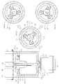
- FIG. 1 is an exploded perspective view of a steer-by-wire type steering apparatus according to the present embodiments.
- FIG. 2 is a perspective view of a part of FIG. 1.
- 3 to 10 are cross-sectional views showing an operating state of the steer-by-wire type steering apparatus according to the present embodiments.
- 11 to 12 are perspective views of a part of the steer-by-wire type steering apparatus according to the present embodiments.
- first, second, A, B, (a), (b) may be used. These terms are only used to distinguish the component from other components, and the nature, order, or order of the component is not limited by the term.
- a component is described as being “connected”, “coupled” or “connected” to another component, the component may be directly connected or connected to that other component, but another component between each component It should be understood that elements may be “connected”, “coupled” or “connected”.
- FIG. 1 is an exploded perspective view of a steer-by-wire type steering apparatus according to the present embodiments
- FIG. 2 is a perspective view of a part of FIG. 1
- FIGS. 3 to 10 are operations of the steer-by-wire type steering apparatus according to the present embodiments
- 11 to 12 are perspective views illustrating a part of the steer-by-wire type steering apparatus according to the present embodiments.
- a steering shaft 106 in which one end of the torsion bar 105 is coupled and a first gear portion 121 is formed on an outer circumferential surface thereof.
- the housing 301 is rotatably coupled to the motor 101, the other end of the torsion bar 105 is coupled, and a second gear portion 122 is formed on the inner circumferential surface by extending in the axial direction on one side
- the first rotor 102 is provided with a hollow receiving portion 112, a third gear portion 123 meshed between the first gear portion 121 and the second gear portion 122 is formed on the outer circumferential surface.
- the steering shaft 106 is connected to the steering wheel 107 and rotated by the operation of the driver, and an electronic control device provided in the vehicle receives data sensed from a torque sensor, an angle sensor, etc. connected to the steering shaft 106. It transmits a signal for steering the wheel calculated therefrom.
- such a sensor may include a motor position sensor for transmitting steering information to the electronic control device, various radars, camera image sensors, and the like, and a detailed description thereof will be omitted below.
- the steering shaft 106 is equipped with a reaction force motor, and the electronic control device operates the reaction force motor based on data sensed from a torque sensor, and generates reaction torque opposite to the steering torque when the driver manipulates the steering wheel 107 Is done.
- the steer-by-wire type steering apparatus 100 includes a motor 101, a torsion bar 105, and a first rotor 102. ), a second rotor 103 and a stopper 104 are provided.
- the torsion bar 105 has one end coupled to the steering shaft 106 and the other end coupled to the first rotor 102.
- One end of the torsion bar 105 may be inserted into and coupled to the inside of the steering shaft 106, and the other end of the torsion bar 105 is inserted into a hole 314 formed on one side of the first rotor 102 Can be combined.
- a serration is formed in the other end of the torsion bar 105 and the hole 314 so that the other end of the torsion bar 105 and the first rotor 102 may be fixedly coupled in the circumferential direction. .
- the first rotor 102 is rotatably coupled to the inside of the housing 301 and connected to the motor 101, but extends in the axial direction on one side in the axial direction toward the steering shaft 106, and a second gear part ( 122) is provided with a hollow receiving portion 112 is formed.
- the second gear part 122 may be formed at the end of the receiving part 112 as shown in the drawing.
- a protrusion 311 is formed on the other side of the first rotor 102 to be coupled through the housing 301 and the bearing 313, which will be described in detail later.
- the torsion bar 105 is located inside the receiving portion 112, the torsion bar 105 is inserted into the receiving portion 112, and the other end of the torsion bar 105 is attached to the first rotor 102. Will be combined.
- the motor 101 is coupled to the first rotor 102 so that the torque of the motor 101 is applied to the first rotor 102, and thus the steering torque of the driver and the steering shaft 106 and the motor 101
- the torsion bar 105 connecting the first rotor 102 is twisted.
- the detailed coupling structure of the first rotor 102 and the motor 101 will be described later.
- a first gear part 121 is formed on the outer circumferential surface of the steering shaft 106 and a second gear part 122 is formed on the inner circumferential surface of the receiving part 112, and a first gear part is formed on the outer circumferential surface of the second rotor 103
- a third gear portion 123 meshed between the 121 and the second gear portion 122 is formed.
- the second rotor 103 is provided with a stopper 104 that limits the rotational angle range of the second rotor 103, and when the reaction force motor reaches the maximum output, the second rotor ( While the rotation of 103 is restricted, rotation of the steering shaft 106 is prevented by the first to third gear units 121, 122, and 123.
- the stopper 104 is provided with a support portion 131 protruding radially outward from the second rotor 103 so that the support portion 131 is supported by the housing 301, the receiving portion 112, and the like, and the second rotor 103
- the rotation angle range of is limited, which will be described later in detail.
- the motor 101 is operated when the reaction force motor reaches the maximum output by the driver's steering torque.
- the stopper 104 is supported on the housing 301 by the operation of the motor 101, and the rotation of the second rotor 103 is restricted, and the rotation of the second rotor 103 is restricted.
- the rotation of the steering shaft 106 meshed with the second rotor 103 is restricted by the gear portions 121, 122, 123.
- two or more of these second rotors 103 may be provided, and a stopper 104 is provided in each of the second rotors 103, thereby being supported on the housing 301 and the like to prevent rotation of the steering shaft 106.
- the number of stoppers 104 increases, and thus stability can be improved.
- the number of stoppers 104 supported on the housing 301 or the like and withstanding the driver's steering torque is increased, and the driver's steering torque is distributed, thereby improving stability.
- the stopper 104 may be formed integrally with the second rotor 103 or may be separately manufactured and combined.
- any one of the stopper 104 and the second rotor 103 is provided with a protrusion 132 protruding in the axial direction,
- the other is provided with an insertion part 133 corresponding to the protrusion 132, so that the protrusion 132 is inserted into the insertion part 133, and the stopper 104 and the second rotor 103 may be coupled.
- the drawing shows an embodiment in which the insertion part 133 is formed in the second rotor 103 and the protrusion 132 is formed in the stopper 104, but as described above, the protrusion 132 in the second rotor 103 Is formed and the insertion portion 133 may be formed in the stopper 104.
- serrations are formed on the outer circumferential surface of the protrusion 132 and the inner circumferential surface of the insertion part 133, so that when the second rotor 103 and the stopper 104 are coupled, they are fixed to each other in the circumferential direction. .
- the stopper 104 for preventing the rotation of the second rotor 103 is provided with a support 131, the support 131 is formed to protrude radially outward from the second rotor 103 do.
- the end of the support 131 draws a circle having a larger radius than the outer circumferential surface of the second rotor 103, so that when the steering shaft 106 is rotated to the right or left
- the support part 131 is supported by the housing 301 and the receiving part 112 and the rotation angle range of the second rotor 103 may be limited.
- This stopper 104 may be provided on at least one of the axial side of the second rotor 103 facing the steering shaft 106 or the other axial side of the second rotor 103 facing the motor 101.
- the position at which the support part 131 is supported may vary when the second rotor 103 is rotated according to a case provided on one side and a case provided on the other side.
- stopper 104 is provided on one of the axial side or the other side of the second rotor 103 is shown in the drawing, but may be provided on both sides.
- the angle range in which the second rotor 103 can be rotated and the support part 131 are supported.
- the position, etc. may vary, which may be appropriately selected in consideration of the torsional stiffness of the torsion bar 105, the maximum torsional angle, and the maximum output of the reaction force motor.
- the stopper 104 When the stopper 104 is provided on one side of the second rotor 103 in the axial direction, first, the second rotor 103 is rotated and the support 131 is supported on the outer circumferential surface of the steering shaft 106 so that the second The range of the rotation angle of the rotor 103 may be limited.
- the second gear part 122 is formed at one end of the receiving part 112 so that when the second rotor 103 is rotated, the stopper 104 is provided with the receiving part 112 ) Or the housing 301, and when the steering shaft 106 is rotated to one side or the other side, the support 131 is supported on the outer circumferential surface of the steering shaft 106, and the rotation of the second rotor 103 is restricted. .
- the support 131 is supported on the outer circumferential surface of the steering shaft 106 and the range in which the second rotor 103 can be rotated is limited by the stopper 104, and thus the rotation of the steering shaft 106 is prevented.
- the support 131 is supported on the outer circumferential surface of the steering shaft 106 or the inner circumferential surface of the housing 301, and the rotation angle range of the second rotor 103 may be limited.
- the support part 131 extends radially than in the first embodiment, so that when the steering shaft 106 is rotated to one side, the support part 131 is the housing 301 When supported on the inner circumferential surface of and rotated to the other side, the support 131 is supported on the outer circumferential surface of the steering shaft 106 and rotation of the second rotor 103 may be restricted.
- the rotatable range of the second rotor 103 will be reduced compared to the case where the aforementioned support 131 is supported only on the outer circumferential surface of the steering shaft 106.
- the support 131 is supported on the inner circumferential surface of the housing 301 or the inner circumferential surface of the receiving unit 112 without being caught on the outer circumferential surface of the steering shaft 106, and the rotation angle range of the second rotor 103 may be limited.
- the steering shaft 106 has an outer circumferential surface on one side in the axial direction relative to the first gear unit 121 It is depressed in the radial direction and a first stepped portion 501 may be formed.
- the stopper 104 when the stopper 104 is rotated together with the second rotor 103, the outer peripheral surface of the steering shaft 106 is recessed in the radial direction, so that the support 131 protruding outward from the second rotor 103 in the radial direction is It is not supported by the steering shaft 106.
- the support 131 when the second rotor 103 is rotated, the support 131 is protruded radially from the inner circumferential surface of the housing 301 so that the support 131 is supported on the inner circumferential surface of the housing 301.
- a second stepped portion 502 opposite to the stepped portion 501 may be formed.
- the support part 131 is supported by the second stepped part 502 and rotation of the second rotor 103 may be restricted.
- the receiving portion 112 when the second rotor 103 is rotated, the receiving portion 112 includes a second gear portion 122 so that the support portion 131 is supported on the inner circumferential surface of the receiving portion 112.
- An extension part 601 extending in one side in the axial direction from the portion where is formed may be formed.
- the support part 131 is supported on the inner circumferential surface of the extension part 601 and rotation of the second rotor 103 may be restricted.
- the support 131 includes the first support 701,1001 and the second support 701,1002, when the second rotor 103 is rotated and the support 131 is supported on the housing 301, etc. Stability can be ensured.
- the first support 701 and the second support 701 are symmetrical with respect to a straight line connecting the center of the second rotor 103 and the center of the steering shaft 106.
- the first support 701 is supported on the outer circumferential surface of the steering shaft 106 and the second support 702 is supported on the inner circumferential surface of the housing 301, or
- the first support 701 is supported on the inner circumferential surface of the housing 301, the second support 702 is supported on the outer circumferential surface of the steering shaft 106, and the second rotor 103 rotates. This can be limited.
- the number of support portions 131 supported on the housing 301 and the like and withstanding the driver's steering torque increases, and the driver's steering torque is distributed, thereby improving stability.
- FIG. 7 shows an embodiment in which the first step portion 501, the second step portion 502, or the extension portion 601 is not formed, but the first step portion 501 or the like is formed to form the second rotor 103 ) May change the rotatable range, and in this case, the angle at which the first support part 701 and the second support part 702 are simultaneously supported by the second rotor 103 may be changed.
- the stopper 104 When the stopper 104 is provided on the other side of the second rotor 103 in the axial direction, first, the second rotor 103 is rotated and the support part 131 is connected to the outer circumferential surface of the steering shaft 106 and the receiving part 112 ), and the rotation angle of the second rotor 103 may be limited.
- the support 131 when the second rotor 103 is rotated, the support 131 is moved between the outer circumferential surface of the steering shaft 106 and the inner circumferential surface of the accommodating part 112, so that the steering shaft ( When 106) is rotated to one side, the support 131 is supported on the inner circumferential surface of the housing 301, and when it is rotated to the other side, the support 131 is supported on the outer circumferential surface of the steering shaft 106, and the second rotor 103 rotates. This can be limited.
- the support part 131 is not caught on the outer circumferential surface of the steering shaft 106 and is supported only on the inner circumferential surface of the accommodating part 112.
- the outer circumferential surface of the other side in the axial direction may be recessed in the radial direction and a recessed portion 901 may be formed.
- the stopper 104 when the stopper 104 is rotated together with the second rotor 103, the outer peripheral surface of the steering shaft 106 is recessed in the radial direction, so that the support 131 protruding outward from the second rotor 103 in the radial direction is It is not supported by the steering shaft 106.
- the support 131 is supported only on the inner circumferential surface of the receiving unit 112 without being caught on the outer circumferential surface of the steering shaft 106 by forming the depression 901,
- the support part 131 is supported on the inner circumferential surface of the receiving part 112 and rotation of the second rotor 103 may be restricted.
- the rotatable range of the second rotor 103 can be increased compared to the sixth embodiment described above.
- the support portion 131 includes the first support portion 1001 and the second support portion 1002, the second rotor 103 is rotated, and the support portion 131 is the housing 301 ) When supported on the back, stability can be secured.
- the first support 1001 and the second support 1002 are symmetrically provided with respect to a straight line connecting the center of the second rotor 103 and the center of the steering shaft 106, so that the steering shaft 106 When rotated, the first support 1001 is supported on the outer circumferential surface of the steering shaft 106 and the second support 1002 is supported on the inner circumferential surface of the housing 301, or when the steering shaft 106 is rotated to the other side.
- the support 1001 is supported on the inner circumferential surface of the housing 301, the second support 1002 is supported on the outer circumferential surface of the steering shaft 106, and rotation of the second rotor 103 may be restricted.
- the number of support portions 131 supported on the housing 301 and the like and withstanding the driver's steering torque increases, and the driver's steering torque is dispersed, thereby improving stability.
- the first rotor 102 is rotatably coupled to the housing 301 to be connected to the motor 101, and the other side of the first rotor 102 has a protrusion 311 protruding in the axial direction. Is provided and the first rotor 102 and the housing 301 may be coupled through a bearing 313 coupled to the protrusion 311.
- a coupling hole 312 is formed in the protrusion 311 so that the motor shaft 111 of the motor 101 is inserted into the coupling hole 312, and the motor 101 is inserted into the first rotor ( 102).
- a serration is formed in the coupling hole 312 and the motor shaft 111 so that the first rotor 102 and the motor shaft 111 may be fixedly coupled in the circumferential direction.
- the protrusion 311 and the motor shaft 111 of the motor 101 may be connected by a belt 1201, and at this time, the diameter of the protrusion 311 is of the motor shaft 111 It can be formed larger than the diameter.
- a gear is formed on the outer circumferential surface of the protrusion 311 and the motor shaft 111 to be connected by the belt 1201.
- the gear ratio of the motor shaft 111 and the first rotor 102 decreases, and the motor 101 transmitted to the first rotor 102 Since the output is amplified, a motor having a small maximum output can be used, thereby reducing the size and weight of the motor 101.
- a damping member may be provided on the outer circumferential surface of the support part 131, and the damping member is provided to absorb the impact sound generated when the support part 131 is supported on the housing 301 or the like.
- the steering shaft is not mechanically rotated any more, thereby increasing the driver's steering sense. I can.
- the protrusion of the first rotor has a larger diameter than the motor shaft of the motor, the gear ratio between the motor and the first rotor is reduced, so that a large torque can be applied to the first rotor even if the motor output is small, so the size and weight of the motor Can reduce.
Landscapes
- Engineering & Computer Science (AREA)
- Mechanical Engineering (AREA)
- General Engineering & Computer Science (AREA)
- Chemical & Material Sciences (AREA)
- Combustion & Propulsion (AREA)
- Transportation (AREA)
- Power Steering Mechanism (AREA)
- Steering Control In Accordance With Driving Conditions (AREA)
Abstract
Description
본 실시예들은 스티어 바이 와이어식 조향장치에 관한 것으로, 보다 상세하게는 운전자가 반력모터의 반력토크보다 큰 조향토크를 조향축에 가하는 경우에 기계적으로 조향축이 더 이상 회전되지 않도록 함으로써 운전자의 조향감각을 상승시킬 수 있는 스티어 바이 와이어식 조향장치에 관한 것이다.The present embodiments relate to a steer-by-wire type steering device, and more particularly, when the driver applies a steering torque greater than the reaction torque of the reaction force motor to the steering shaft, the steering shaft is not mechanically rotated any more, thereby steering the driver. It relates to a steer-by-wire type steering system capable of raising the senses.
스티어 바이 와이어식 조향장치란 일종의 전동식 조향장치로서, 조향휠과 전륜 조향장치 사이에 조향컬럼, 유니버셜 조인트 등 기계적인 연결 없이 전기적인 동력을 이용하여 차량을 조타시키는 장치를 말한다.A steer-by-wire type steering device is a type of electric steering device, and refers to a device that uses electrical power to steer a vehicle without mechanical connection such as a steering column or universal joint between the steering wheel and the front wheel steering device.
즉, 운전자의 조향휠 조작이 전기 신호로 변환되어 전자제어장치에서 이를 입력받게 되고 그에 따라 모터의 출력이 결정되게 되는데, 이러한 스티어 바이 와이어식 시스템은 기계적인 연결이 없으므로 충돌 시 기구부에 의한 운전자 상해를 감소시키며 기계적 연결 및 유압부품 삭감이 가능하므로 부품수 축소로 차량의 경량화 및 라인 조립공수 급감 등의 단순화로 조향 작동 시의 불필요한 에너지 소모를 줄임으로서 연비를 향상시킨다. 또한, ECU 프로그래밍에 의하여 이상적인 조향 성능 달성이 가능하다.In other words, the steering wheel operation of the driver is converted into an electric signal, which is inputted from the electronic control device, and the motor output is determined accordingly.This steer-by-wire system does not have a mechanical connection, so the driver injury due to the mechanical part in the event of a collision. It reduces the number of components and reduces the number of mechanical connections and hydraulic parts, so it improves fuel economy by reducing unnecessary energy consumption during steering operation by reducing the number of parts and simplifying the vehicle weight reduction and rapid reduction in line assembly work. In addition, it is possible to achieve ideal steering performance by programming the ECU.
그런데, 이러한 스티어 바이 와이어식 조향장치의 경우 조향축과 바퀴와의 기계적인 연결이 없기 때문에 운전자의 조향휠 회전이 무한정 회전할 수 있어서 운전자의 조향감각을 떨어트리는 문제가 있었다.However, in the case of such a steer-by-wire type steering device, since there is no mechanical connection between the steering shaft and the wheel, the driver's steering wheel rotation can be infinitely rotated, thereby deteriorating the driver's steering sense.
즉, 바퀴의 회전이 최대점에 이른 경우(일반적인 조향장치에서 조향휠 또는 바퀴가 풀턴 상태인 경우)나 바퀴가 도로의 연석에 부딪혀 더 이상 회전할 수 없는 경우 등에는 조향축이 더 이상 회전되지 않도록 함으로써 운전자에게 이러한 정보를 줄 수 있는 필요성이 대두되고 있다.In other words, when the rotation of the wheel reaches its maximum point (when the steering wheel or wheel is in a full-turn state in a general steering system), or when the wheel hits the curb of the road and can no longer rotate, the steering shaft is no longer rotated. There is a need to be able to give this information to the driver by doing so.
본 실시예들은 전술한 배경에서 안출된 것으로, 운전자가 반력모터의 반력토크보다 큰 조향토크를 조향축에 가하는 경우에 기계적으로 조향축이 더 이상 회전되지 않도록 함으로써 운전자의 조향감각을 상승시킬 수 있는 것을 목적으로 한다.These embodiments were devised from the above-described background, and when the driver applies a steering torque greater than the reaction torque of the reaction force motor to the steering shaft, the steering shaft is not mechanically rotated any more, thereby increasing the driver's steering sense. It is aimed at.
본 실시예들의 목적은 여기에 제한되지 않으며, 언급되지 않은 또 다른 목적들은 아래의 기재로부터 통상의 기술자에게 명확하게 이해될 수 있을 것이다.The purpose of the present embodiments is not limited thereto, and other objects not mentioned will be clearly understood by those skilled in the art from the following description.
본 실시예들에 의하면, 토션바의 일단부가 결합되고 외주면에 제 1 기어부가 형성되는 조향축, 하우징 내부에 회전가능하게 결합되어 모터와 연결되며 토션바의 타단부가 결합되고 일측면에는 축방향으로 연장되어 내주면에 제 2 기어부가 형성되는 중공의 수용부가 구비되는 제 1 로터, 외주면에 제 1 기어부와 제 2 기어부 사이에 맞물리는 제 3 기어부가 형성되는 제 2 로터, 제 2 로터에 구비되며, 제 1 기어부와 제 2 기어부 사이에서 제 2 로터가 회전될 때 제 2 로터의 회전각도 범위를 제한하는 스토퍼를 포함하는 스티어 바이 와이어식 조향장치가 제공될 수 있다.According to the present embodiments, one end of the torsion bar is coupled and a steering shaft having a first gear unit formed on the outer circumferential surface thereof, is rotatably coupled to the inside of the housing and connected to the motor, and the other end of the torsion bar is coupled, and the axial direction is at one side. The first rotor is provided with a hollow receiving portion extending from the inner circumferential surface to form a second gear unit, a second rotor having a third gear unit meshing between the first and second gear units on the outer circumferential surface, and the second rotor A steer-by-wire type steering apparatus including a stopper for limiting a range of a rotation angle of the second rotor when the second rotor is rotated between the first gear unit and the second gear unit may be provided.
본 실시예들에 의하면, 운전자가 반력모터의 반력토크보다 큰 조향토크를 조향축에 가하는 경우에 기계적으로 조향축이 더 이상 회전되지 않도록 함으로써 운전자의 조향감각을 상승시킬 수 있다.According to the present embodiments, when the driver applies a steering torque larger than the reaction torque of the reaction force motor to the steering shaft, the steering sensation of the driver can be increased by mechanically preventing the steering shaft from rotating any more.
도 1은 본 실시예들에 의한 스티어 바이 와이어식 조향장치의 분해사시도이다.1 is an exploded perspective view of a steer-by-wire type steering apparatus according to the present embodiments.
도 2는 도 1의 일부에 대한 사시도이다.FIG. 2 is a perspective view of a part of FIG. 1.
도 3 내지 도 10은 본 실시예들에 의한 스티어 바이 와이어식 조향장치의 동작상태를 나타내는 단면도이다.3 to 10 are cross-sectional views showing an operating state of the steer-by-wire type steering apparatus according to the present embodiments.
도 11 내지 도 12는 본 실시예들에 의한 스티어 바이 와이어식 조향장치의 일부에 대한 사시도이다.11 to 12 are perspective views of a part of the steer-by-wire type steering apparatus according to the present embodiments.
이하, 본 실시예들의 일부 실시예들을 예시적인 도면을 통해 상세하게 설명한다. 각 도면의 구성요소들에 참조부호를 부가함에 있어서, 동일한 구성요소들에 대해서는 비록 다른 도면상에 표시되더라도 가능한 한 동일한 부호를 가지도록 하고 있음에 유의해야 한다. 또한, 본 실시예들을 설명함에 있어, 관련된 공지 구성 또는 기능에 대한 구체적인 설명이 본 실시예들의 요지를 흐릴 수 있다고 판단되는 경우에는 그 상세한 설명은 생략한다.Hereinafter, some embodiments of the present embodiments will be described in detail through exemplary drawings. In adding reference numerals to elements of each drawing, it should be noted that the same elements are assigned the same numerals as possible even if they are indicated on different drawings. In addition, in describing the embodiments, if it is determined that a detailed description of a related known configuration or function may obscure the subject matter of the embodiments, the detailed description thereof will be omitted.
또한, 본 실시예들의 구성 요소를 설명하는 데 있어서, 제 1, 제 2, A, B, (a), (b) 등의 용어를 사용할 수 있다. 이러한 용어는 그 구성 요소를 다른 구성 요소와 구별하기 위한 것일 뿐, 그 용어에 의해 해당 구성 요소의 본질이나 차례 또는 순서 등이 한정되지 않는다. 어떤 구성 요소가 다른 구성요소에 "연결", "결합" 또는 "접속"된다고 기재된 경우, 그 구성 요소는 그 다른 구성요소에 직접적으로 연결되거나 또는 접속될 수 있지만, 각 구성 요소 사이에 또 다른 구성 요소가 "연결", "결합" 또는 "접속"될 수도 있다고 이해되어야 할 것이다.In addition, in describing the constituent elements of the present embodiments, terms such as first, second, A, B, (a), (b) may be used. These terms are only used to distinguish the component from other components, and the nature, order, or order of the component is not limited by the term. When a component is described as being "connected", "coupled" or "connected" to another component, the component may be directly connected or connected to that other component, but another component between each component It should be understood that elements may be “connected”, “coupled” or “connected”.
도 1은 본 실시예들에 의한 스티어 바이 와이어식 조향장치의 분해사시도, 도 2는 도 1의 일부에 대한 사시도, 도 3 내지 도 10은 본 실시예들에 의한 스티어 바이 와이어식 조향장치의 동작상태를 나타내는 단면도, 도 11 내지 도 12는 본 실시예들에 의한 스티어 바이 와이어식 조향장치의 일부에 대한 사시도이다.1 is an exploded perspective view of a steer-by-wire type steering apparatus according to the present embodiments, FIG. 2 is a perspective view of a part of FIG. 1, and FIGS. 3 to 10 are operations of the steer-by-wire type steering apparatus according to the present embodiments. 11 to 12 are perspective views illustrating a part of the steer-by-wire type steering apparatus according to the present embodiments.
이들 도면을 참고하여 살펴보면, 본 실시예들에 의한 스티어 바이 와이어식 조향장치(100)는, 토션바(105)의 일단부가 결합되고 외주면에 제 1 기어부(121)가 형성되는 조향축(106), 하우징(301) 내부에 회전가능하게 결합되어 모터(101)와 연결되며 토션바(105)의 타단부가 결합되고 일측면에는 축방향으로 연장되어 내주면에 제 2 기어부(122)가 형성되는 중공의 수용부(112)가 구비되는 제 1 로터(102), 외주면에 제 1 기어부(121)와 제 2 기어부(122) 사이에 맞물리는 제 3 기어부(123)가 형성되는 제 2 로터(103), 제 2 로터(103)에 구비되며 제 1 기어부(121)와 제 2 기어부(122) 사이에서 제 2 로터(103)가 회전될 때 제 2 로터(103)의 회전각도 범위를 제한하는 스토퍼(104)를 포함한다.Referring to these drawings, in the steer-by-wire
조향축(106)은 조향휠(107)과 연결되어 운전자의 조작에 의해 회전되는데, 자동차에 구비되는 전자제어장치가 조향축(106)에 연결된 토크센서, 앵글센서 등으로부터 센싱된 데이터를 수신하고 그로부터 산출되는 바퀴를 조타하기 위한 신호를 송신하게 된다.The
이러한 센서는 조향정보를 전자제어장치로 송신하기 위한 모터 포지션센서와 각종 레이더, 카메라 화상센서 등을 포함할 수 있음은 물론이며, 이하 이에 대한 자세한 설명은 생략하기로 한다.Of course, such a sensor may include a motor position sensor for transmitting steering information to the electronic control device, various radars, camera image sensors, and the like, and a detailed description thereof will be omitted below.
조향축(106)에는 반력모터가 구비되는데, 토크센서 등으로부터 센싱된 데이터에 기초하여 전자제어장치가 반력모터를 작동시켜 운전자의 조향휠(107) 조작 시 조향토크와 반대방향의 반력토크를 생성하게 된다.The
이러한 스티어 바이 와이어식 조향장치에 있어서는 조향축(106)과 바퀴가 기계적으로 연결되어 있지 않기 때문에 운전자가 조향휠(107)을 무한정 회전시킬 수 있어서, 임의의 각도에서 회전을 멈추게 하는 기계적 제한이 필요하다.In such a steer-by-wire type steering device, since the
즉, 조향휠(107)이 최대 회전수에 도달하거나 바퀴가 도로의 연석에 부딪혀 고착되는 등의 경우에 운전자의 조향토크가 커짐에 따라 반력모터의 반력토크도 커지게 되는데, 반력모터가 최대출력에 도달하였을 경우 조향축(106)이 더 이상 회전되지 않게 하기 위해, 본 실시예들에 따른 스티어 바이 와이어식 조향장치(100)에는 모터(101), 토션바(105), 제 1 로터(102), 제 2 로터(103) 및 스토퍼(104) 등이 구비되게 된다.That is, when the
토션바(105)는 일단부가 조향축(106)과 결합되고 타단부가 제 1 로터(102)와 결합된다.The
토션바(105)의 일단부는 조향축(106)의 내부로 삽입되어 결합될 수 있으며, 토션바(105)의 타단부는 제 1 로터(102)의 일측면에 형성된 홀(314)에 삽입되어 결합될 수 있다. 도면에는 도시되지 않았으나, 토션바(105)의 타단부와 홀(314)에는 세레이션이 형성되어 토션바(105)의 타단부와 제 1 로터(102)는 원주방향으로 고정되게 결합될 수 있다.One end of the
제 1 로터(102)는 하우징(301) 내부에 회전 가능하게 결합되어 모터(101)와 연결되되, 조향축(106)을 향하는 축방향 일측면에는 축방향으로 연장되어 내주면에 제 2 기어부(122)가 형성되는 중공의 수용부(112)가 구비된다. 이러한 제 2 기어부(122)는 도면에 도시된 바와 같이 수용부(112)의 단부에 형성될 수 있다. 제 1 로터(102)의 타측면에는 돌출부(311)가 형성되어 하우징(301)과 베어링(313)을 매개로 결합될 수 있는데, 자세한 내용은 후술한다.The
즉, 토션바(105)는 수용부(112)의 내측에 위치하여, 토션바(105)가 수용부(112) 내부로 삽입되며 토션바(105)의 타단부가 제 1 로터(102)에 결합되게 된다.That is, the
제 1 로터(102)에는 모터(101)가 결합되어 모터(101)의 토크가 제 1 로터(102)에 가해지게 되며, 따라서 운전자의 조향토크와 모터(101)에 의해 조향축(106)과 제 1 로터(102)를 연결하는 토션바(105)가 비틀리게 된다. 제 1 로터(102)와 모터(101)의 자세한 결합구조에 관해서는 후술한다.The
조향축(106)의 외주면에는 제 1 기어부(121)가 형성되고 수용부(112)의 내주면에는 제 2 기어부(122)가 형성되는데, 제 2 로터(103)의 외주면에는 제 1 기어부(121)와 제 2 기어부(122) 사이에 맞물리는 제 3 기어부(123)가 형성된다.A
이 때, 제 2 로터(103)에는 제 2 로터(103)의 회전각도 범위를 제한하는 스토퍼(104)가 구비되어, 반력모터가 최대출력에 도달하였을 경우 스토퍼(104)에 의해 제 2 로터(103)의 회전이 제한되면서 제 1 내지 제 3 기어부(121,122,123)에 의해 조향축(106)의 회전이 방지되게 된다.At this time, the
다시 말해, 반력모터가 최대출력에 도달하였을 경우 모터(101)가 작동되고 토션바(105)가 비틀리며 양단, 즉 조향축(106)과 제 1 로터(102) 사이에 위상차가 발생하게 되는데, 위상차에 의해 조향축(106)에 형성된 제 1 기어부(121)와 제 1 로터(102)에 형성된 제 2 기어부(122)의 사이에 구비되는 제 2 로터(103)가 회전되게 되고, 스토퍼(104)에 의해 제 2 로터(103)의 회전이 제한됨으로써 기계적으로 조향축(106)의 회전이 방지되게 된다.In other words, when the reaction force motor reaches the maximum output, the
이러한 스토퍼(104)에는 제 2 로터(103)에서 경방향 외측으로 돌출되는 지지부(131)가 구비되어 지지부(131)가 하우징(301), 수용부(112) 등에 지지되며 제 2 로터(103)의 회전각도 범위를 제한하게 되는데, 자세한 내용은 후술한다.The
도면에는 지지부(131)가 타원형상으로 구비되는 실시예들이 도시되어 있으나, 반드시 이에 한정되는 것은 아니며 다른 형상으로 형성될 수도 있다.In the drawings, embodiments in which the
스토퍼(104)에 의해 제 2 로터(103)의 회전이 제한되어 조향축(106)의 회전이 방지되는 과정을 자세히 설명하자면, 우선, 바퀴가 자유로이 조타될 수 있는 상황에서는 조향축(106), 제 1 로터(102) 및 제 2 로터(103)가 조향축(106)의 중심축을 기준으로 함께 회전되게 된다. 이 때 반력모터는 최대출력에 도달하지 않으므로 모터(101)는 작동되지 않는다.To explain in detail the process in which the rotation of the
그리고, 조향휠(107)이 최대 회전수에 도달하거나 바퀴가 도로의 연석에 부딪혀 고착되는 등의 경우에, 운전자의 조향토크에 의해 반력모터가 최대출력에 도달하게 되면 모터(101)가 작동되고, 모터(101)의 작동에 의해 스토퍼(104)가 하우징(301) 등에 지지되며 제 2 로터(103)의 회전이 제한되게 되고, 제 2 로터(103)의 회전이 제한됨에 따라 제 1 내지 제 3 기어부(121,122,123)에 의해 제 2 로터(103)와 맞물리는 조향축(106)의 회전이 제한되게 된다.And, in the case where the
한편, 이러한 제 2 로터(103)는 둘 이상 구비될 수 있으며, 제 2 로터(103) 각각에 스토퍼(104)가 구비됨으로써 조향축(106)의 회전을 방지하기 위해 하우징(301) 등에 지지되는 스토퍼(104)의 개수가 증가하게 되고 따라서 안정성이 향상될 수 있다.Meanwhile, two or more of these
즉, 하우징(301) 등에 지지되며 운전자의 조향토크를 견디는 스토퍼(104)의 개수가 증가되며 운전자의 조향토크가 분산되므로 안정성이 향상되게 된다.That is, the number of
도면에는 일례로 제 2 로터(103)가 세 개 구비되는 실시예가 도시되었으며, 반드시 이에 한정되는 것은 아니고 더 많은 개수로 구비될 수도 있을 것이다.In the drawing, as an example, an embodiment in which three
한편, 이러한 스토퍼(104)는 제 2 로터(103)와 일체로 형성되거나, 또는 별도로 제작되어 결합될 수도 있다.Meanwhile, the
도 2를 참고하여 살펴보면 스토퍼(104)와 제 2 로터(103)가 별도로 제작되는 경우, 스토퍼(104)와 제 2 로터(103) 중 어느 하나에는 축방향으로 돌출되는 돌기부(132)가 구비되고 다른 하나에는 돌기부(132)에 대응되는 삽입부(133)가 구비되어, 돌기부(132)가 삽입부(133)에 삽입되며 스토퍼(104)와 제 2 로터(103)가 결합될 수 있다.Referring to FIG. 2, when the
도면에는 제 2 로터(103)에 삽입부(133)가 형성되고 스토퍼(104)에 돌기부(132)가 형성되는 실시예가 도시되어 있으나, 전술한 바와 같이 제 2 로터(103)에 돌기부(132)가 형성되고 스토퍼(104)에 삽입부(133)가 형성될 수도 있을 것이다.The drawing shows an embodiment in which the
도면에 도시된 바와 같이, 돌기부(132)의 외주면과 삽입부(133)의 내주면에는 세레이션이 형성되어, 제 2 로터(103)와 스토퍼(104)가 결합되었을 때 서로 원주방향으로 고정되게 된다.As shown in the figure, serrations are formed on the outer circumferential surface of the
한편, 전술한 바와 같이 제 2 로터(103)의 회전을 방지하기 위한 스토퍼(104)에는 지지부(131)가 구비되는데, 지지부(131)는 제 2 로터(103)에서 경방향 외측으로 돌출되게 형성된다.On the other hand, as described above, the
즉, 제 2 로터(103)가 회전할 때 지지부(131)의 단부가 제 2 로터(103)의 외주면보다 큰 반경을 가지는 원을 그리게 되어, 조향축(106)이 우측 또는 좌측으로 회전될 때 지지부(131)가 하우징(301), 수용부(112) 등에 지지되며 제 2 로터(103)의 회전각도 범위가 제한될 수 있다.That is, when the
이러한 스토퍼(104)는 제 2 로터(103)의 조향축(106)을 향하는 축방향 일측면, 또는 제 2 로터(103)의 모터(101)를 향하는 축방향 타측면 중 적어도 어느 하나에 구비될 수 있으며, 일측면에 구비되는 경우와 타측면에 구비되는 경우에 따라 제 2 로터(103)가 회전될 때 지지부(131)가 지지되는 위치가 달라질 수 있다.This
다시 말해, 도면에는 스토퍼(104)가 제 2 로터(103)의 축방향 일측면 또는 타측면 중 어느 하나에 구비되는 경우만 도시되어 있으나, 양측 모두에 구비될 수도 있다.In other words, only a case where the
또한, 지지부(131)의 두께, 하우징(301) 또는 수용부(112)의 내경, 조향축(106)의 외경 등에 따라 제 2 로터(103)가 회전가능한 각도범위 및 지지부(131)가 지지되는 위치 등이 달라질 수 있는데, 이는 토션바(105)의 비틀림 강성, 최대 비틀림 각도 및 반력모터의 최대출력 등을 고려하여 적절히 선택할 수 있을 것이다.In addition, depending on the thickness of the
스토퍼(104)가 제 2 로터(103)의 축방향 일측면에 구비되는 경우에는, 먼저, 제 2 로터(103)가 회전되며 지지부(131)가 조향축(106)의 외주면에 지지되어 제 2 로터(103)의 회전각도 범위가 제한될 수 있다.When the
도 3에 도시된 제 1 실시예를 살펴보면, 제 2 기어부(122)는 수용부(112)의 일측단부에 형성되어 제 2 로터(103)가 회전될 때 스토퍼(104)가 수용부(112) 또는 하우징(301)에 걸리지 않으며, 조향축(106)이 일측 또는 타측으로 회전될 때 지지부(131)가 조향축(106)의 외주면에 지지되며 제 2 로터(103)의 회전이 제한되게 된다.Referring to the first embodiment shown in FIG. 3, the
지지부(131)가 조향축(106)의 외주면에 지지되며 스토퍼(104)에 의해 제 2 로터(103)가 회전가능한 범위가 제한되게 되고, 따라서 조향축(106)의 회전이 방지되게 된다.The
또는, 지지부(131)가 조향축(106)의 외주면 또는 하우징(301)의 내주면에 지지되며 제 2 로터(103)의 회전각도 범위가 제한될 수 있다.Alternatively, the
도 4에 도시된 제 2 실시예를 살펴보면, 전술한 제 1 실시예보다 지지부(131)가 경방향으로 연장되어, 조향축(106)이 일측으로 회전될 때 지지부(131)가 하우징(301)의 내주면에 지지되고 타측으로 회전될 때 지지부(131)가 조향축(106)의 외주면에 지지되며 제 2 로터(103)의 회전이 제한될 수 있다.Referring to the second embodiment shown in FIG. 4, the
이 경우에는 제 2 로터(103)의 회전가능한 범위가 전술한 지지부(131)가 조향축(106)의 외주면에만 지지되는 경우보다 줄어들게 될 것이다.In this case, the rotatable range of the
또는, 지지부(131)가 조향축(106)의 외주면에 걸리지 않고 하우징(301)의 내주면 또는 수용부(112)의 내주면에 지지되며 제 2 로터(103)의 회전각도 범위가 제한될 수 있다.Alternatively, the
이 때, 제 2 로터(103)가 회전될 때 지지부(131)가 조향축(106)의 외주면에 걸리지 않도록, 조향축(106)에는 제 1 기어부(121)를 기준으로 축방향 일측의 외주면이 경방향으로 함몰되며 제 1 단차부(501)가 형성될 수 있다.At this time, when the
즉, 제 2 로터(103)와 함께 스토퍼(104)가 회전될 때, 조향축(106)의 외주면이 경방향으로 함몰됨으로써 제 2 로터(103)에서 경방향 외측으로 돌출되는 지지부(131)가 조향축(106)에 지지되지 않게 된다.That is, when the
도 5에 도시된 제 3 실시예를 살펴보면, 제 2 로터(103)가 회전될 때 지지부(131)가 하우징(301)의 내주면에 지지되도록 하우징(301)의 내주면에는 경방향으로 돌출되어 제 1 단차부(501)와 대향되는 제 2 단차부(502)가 형성될 수 있다.Referring to the third embodiment shown in FIG. 5, when the
즉, 조향축(106)이 일측 또는 타측으로 회전될 때 지지부(131)가 제 2 단차부(502)에 지지되며 제 2 로터(103)의 회전이 제한될 수 있다.That is, when the
도 6에 도시된 제 4 실시예를 살펴보면, 제 2 로터(103)가 회전될 때 지지부(131)가 수용부(112)의 내주면에 지지되도록 수용부(112)에는 제 2 기어부(122)가 형성된 부위에서 축방향 일측으로 연장되는 연장부(601)가 형성될 수 있다.Referring to the fourth embodiment shown in FIG. 6, when the
즉, 조향축(106)이 일측 또는 타측으로 회전될 때 지지부(131)가 연장부(601)의 내주면에 지지되며 제 2 로터(103)의 회전이 제한될 수 있다.That is, when the
또는, 지지부(131)는 제 1 지지부(701,1001)와 제 2 지지부(701,1002)를 포함하여, 제 2 로터(103)가 회전되며 지지부(131)가 하우징(301) 등에 지지될 때 안정성을 확보할 수 있다.Alternatively, the
도 7에 도시된 제 5 실시예를 살펴보면, 제 1 지지부(701)와 제 2 지지부(701)는 제 2 로터(103)의 중심과 조향축(106)의 중심을 잇는 직선을 기준으로 대칭되게 구비되어, 조향축(106)이 일측으로 회전될 때 제 1 지지부(701)가 조향축(106)의 외주면에 지지되고 제 2 지지부(702)가 하우징(301)의 내주면에 지지되거나, 조향축(106)이 타측으로 회전될 때 제 1 지지부(701)가 하우징(301)의 내주면에 지지되고 제 2 지지부(702)가 조향축(106)의 외주면에 지지되며 제 2 로터(103)의 회전이 제한될 수 있다.Referring to the fifth embodiment shown in FIG. 7, the
즉, 하우징(301) 등에 지지되며 운전자의 조향토크를 견디는 지지부(131)의 개수가 늘어나며 운전자의 조향토크가 분산되므로 안정성이 향상되게 된다.That is, the number of
도 7에는 제 1 단차부(501), 제 2 단차부(502) 또는 연장부(601)가 형성되지 않은 실시예가 도시되어 있으나, 제 1 단차부(501) 등이 형성되어 제 2 로터(103)가 회전가능한 범위를 변경할 수도 있을 것이며, 이러한 경우 제 1 지지부(701)와 제 2 지지부(702)가 동시에 지지되기 위해 제 2 로터(103)에 결합되는 각도가 달라질 수 있다.7 shows an embodiment in which the
스토퍼(104)가 제 2 로터(103)의 축방향 타측면에 구비되는 경우에는, 먼저, 제 2 로터(103)가 회전되며 지지부(131)가 조향축(106)의 외주면과 수용부(112)의 내주면에 지지되며 제 2 로터(103)의 회전각도가 제한될 수 있다.When the
도 8에 도시된 제 6 실시예를 살펴보면, 제 2 로터(103)가 회전될 때 지지부(131)는 조향축(106)의 외주면과 수용부(112)의 내주면 사이에서 이동되어, 조향축(106)이 일측으로 회전될 때 지지부(131)가 하우징(301)의 내주면에 지지되고 타측으로 회전될 때 지지부(131)가 조향축(106)의 외주면에 지지되며 제 2 로터(103)의 회전이 제한될 수 있다.Referring to the sixth embodiment shown in FIG. 8, when the
또는, 제 2 로터(103)가 회전될 때 지지부(131)가 조향축(106)의 외주면에 걸리지 않고 수용부(112)의 내주면에만 지지되도록, 조향축(106)에는 제 1 기어부(121)를 기준으로 축방향 타측의 외주면이 경방향으로 함몰되며 함몰부(901)가 형성될 수 있다.Alternatively, when the
즉, 제 2 로터(103)와 함께 스토퍼(104)가 회전될 때, 조향축(106)의 외주면이 경방향으로 함몰됨으로써 제 2 로터(103)에서 경방향 외측으로 돌출되는 지지부(131)가 조향축(106)에 지지되지 않게 된다.That is, when the
도 9에 도시된 제 7 실시예를 살펴보면, 함몰부(901)가 형성됨으로써 지지부(131)는 조향축(106)의 외주면에 걸리지 않고 수용부(112)의 내주면에만 지지되게 되며, 조향축(106)이 일측 또는 타측으로 회전될 때 지지부(131)가 수용부(112)의 내주면에 지지되며 제 2 로터(103)의 회전이 제한될 수 있다.Referring to the seventh embodiment shown in FIG. 9, the
이 경우, 전술한 제 6 실시예보다 제 2 로터(103)의 회전가능한 범위가 증가될 수 있다.In this case, the rotatable range of the
도 10에 도시된 제 8 실시예를 살펴보면, 지지부(131)가 제 1 지지부(1001)와 제 2 지지부(1002)를 포함하여 제 2 로터(103)가 회전되며 지지부(131)가 하우징(301) 등에 지지될 때 안정성을 확보할 수 있다.Referring to the eighth embodiment shown in FIG. 10, the
이러한 제 1 지지부(1001)와 제 2 지지부(1002)는 제 2 로터(103)의 중심과 조향축(106)의 중심을 잇는 직선을 기준으로 대칭되게 구비되어, 조향축(106)이 일측으로 회전될 때 제 1 지지부(1001)가 조향축(106)의 외주면에 지지되고 제 2 지지부(1002)가 하우징(301)의 내주면에 지지되거나, 조향축(106)이 타측으로 회전될 때 제 1 지지부(1001)가 하우징(301)의 내주면에 지지되고 제 2 지지부(1002)가 조향축(106)의 외주면에 지지되며 제 2 로터(103)의 회전이 제한될 수 있다.The
즉, 전술한 바와 같이, 하우징(301) 등에 지지되며 운전자의 조향토크를 견디는 지지부(131)의 개수가 늘어나며 운전자의 조향토크가 분산되므로 안정성이 향상되게 된다.That is, as described above, the number of
이와 같이 지지부(131)가 하우징(301) 등에 지지되며 제 2 로터(103)의 회전각도 범위가 제한됨에 따라, 반력모터가 최대출력에 도달하였을 경우 모터(101)가 작동되며 조향축(106)의 회전을 방지할 수 있게 된다.In this way, as the
한편, 전술한 바와 같이 제 1 로터(102)는 하우징(301)에 회전가능하게 결합되어 모터(101)와 연결되는데, 제 1 로터(102)의 타측면에는 축방향으로 돌출되는 돌출부(311)가 구비되고 제 1 로터(102)와 하우징(301)은 돌출부(311)에 결합되는 베어링(313)을 매개로 결합될 수 있다.Meanwhile, as described above, the
또한, 도 11을 참고하여 살펴보면, 돌출부(311)에는 결합홀(312)이 형성되어 모터(101)의 모터축(111)이 결합홀(312)에 삽입되며 모터(101)가 제 1 로터(102)와 결합될 수 있다. 결합홀(312)과 모터축(111)에는 세레이션이 형성되어 제 1 로터(102)와 모터축(111)은 원주방향으로 고정되게 결합될 수 있다.In addition, referring to FIG. 11, a
또한, 도 12를 참고하여 살펴보면, 돌출부(311)와 모터(101)의 모터축(111)은 벨트(1201)에 의해 연결될 수 있으며, 이 때 돌출부(311)의 직경은 모터축(111)의 직경보다 크게 형성될 수 있다.In addition, referring to FIG. 12, the
이 때, 돌출부(311)와 모터축(111)의 외주면에는 기어가 형성되어 벨트(1201)에 의해 연결될 수 있다.At this time, a gear is formed on the outer circumferential surface of the
돌출부(311)의 직경이 모터축(111)의 직경보다 크게 형성될 때 모터축(111)과 제 1 로터(102)의 기어비가 감소하며 제 1 로터(102)에 전달되는 모터(101)의 출력이 증폭되므로, 최대출력이 작은 모터를 사용할 수 있어 모터(101)의 크기와 무게를 감소시킬 수 있다.When the diameter of the
한편, 도면에는 도시되지 않았으나 지지부(131)의 외주면에는 댐핑부재가 구비될 수 있는데, 댐핑부재가 구비됨으로써 지지부(131)가 하우징(301) 등에 지지될 때 발생하는 충격음을 흡수할 수 있다.Meanwhile, although not shown in the drawings, a damping member may be provided on the outer circumferential surface of the
즉, 조향축(106)이 회전하며 지지부(131)가 하우징(301) 등에 지지될 때 댐핑부재에 의해 충돌이 완화되므로 충격음을 감소시킬 수 있다.That is, when the
이와 같은 형상을 갖는 스티어 바이 와이어식 조향장치에 의하면, 운전자가 반력모터의 반력토크보다 큰 조향토크를 조향축에 가하는 경우에 기계적으로 조향축이 더 이상 회전되지 않도록 함으로써 운전자의 조향감각을 상승시킬 수 있다.According to the steer-by-wire type steering device having such a shape, when the driver applies a steering torque larger than the reaction torque of the reaction force motor to the steering shaft, the steering shaft is not mechanically rotated any more, thereby increasing the driver's steering sense. I can.
또한, 제 1 로터의 돌출부가 모터의 모터축보다 큰 직경으로 형성됨으로써, 모터와 제 1 로터의 기어비가 감소되어 모터의 출력이 작더라도 제 1 로터에 큰 토크를 가할 수 있어 모터의 크기와 무게를 감소시킬 수 있다.In addition, since the protrusion of the first rotor has a larger diameter than the motor shaft of the motor, the gear ratio between the motor and the first rotor is reduced, so that a large torque can be applied to the first rotor even if the motor output is small, so the size and weight of the motor Can reduce.
이상에서, 본 실시예들의 실시예를 구성하는 모든 구성 요소들이 하나로 결합되거나 결합되어 동작하는 것으로 설명되었다고 해서, 본 실시예들이 반드시 이러한 실시예에 한정되는 것은 아니다. 즉, 본 실시예들의 목적 범위 안에서라면, 그 모든 구성 요소들이 하나 이상으로 선택적으로 결합하여 동작할 수도 있다.In the above, just because all the constituent elements constituting the embodiments of the embodiments are described as being combined into one or operating in combination, the embodiments are not necessarily limited to these embodiments. That is, as long as it is within the scope of the objectives of the present embodiments, one or more of the components may be selectively combined and operated.
또한, 이상에서 기재된 "포함하다", "구성하다" 또는 "가지다" 등의 용어는, 특별히 반대되는 기재가 없는 한, 해당 구성 요소가 내재될 수 있음을 의미하는 것이므로, 다른 구성 요소를 제외하는 것이 아니라 다른 구성 요소를 더 포함할 수 있는 것으로 해석되어야 한다. 기술적이거나 과학적인 용어를 포함한 모든 용어들은, 다르게 정의되지 않는 한, 본 실시예들이 속하는 기술 분야에서 통상의 지식을 가진 자에 의해 일반적으로 이해되는 것과 동일한 의미를 가진다. 사전에 정의된 용어와 같이 일반적으로 사용되는 용어들은 관련 기술의 문맥 상의 의미와 일치하는 것으로 해석되어야 하며, 본 실시예들에서 명백하게 정의하지 않는 한, 이상적이거나 과도하게 형식적인 의미로 해석되지 않는다.In addition, the terms such as "include", "consist of" or "have" described above mean that the corresponding component may be embedded unless otherwise stated, excluding other components Rather, it should be interpreted as being able to further include other components. All terms, including technical or scientific terms, unless otherwise defined, have the same meaning as commonly understood by one of ordinary skill in the art to which the present embodiments belong. Terms commonly used, such as terms defined in the dictionary, should be interpreted as being consistent with the meaning in the context of the related technology, and are not interpreted as ideal or excessively formal meanings unless explicitly defined in the present embodiments.
이상의 설명은 본 실시예들의 기술 사상을 예시적으로 설명한 것에 불과한 것으로서, 본 실시예들이 속하는 기술 분야에서 통상의 지식을 가진 자라면 본 실시예들의 본질적인 특성에서 벗어나지 않는 범위에서 다양한 수정 및 변형이 가능할 것이다. 따라서, 본 실시예들에 개시된 실시예들은 본 실시예들의 기술 사상을 한정하기 위한 것이 아니라 설명하기 위한 것이고, 이러한 실시예에 의하여 본 실시예들의 기술 사상의 범위가 한정되는 것은 아니다. 본 실시예들의 보호 범위는 아래의 청구범위에 의하여 해석되어야 하며, 그와 동등한 범위 내에 있는 모든 기술 사상은 본 실시예들의 권리범위에 포함되는 것으로 해석되어야 할 것이다.The above description is merely illustrative of the technical idea of the present embodiments, and those of ordinary skill in the technical field to which the present embodiments belong can make various modifications and variations without departing from the essential characteristics of the present embodiments. will be. Accordingly, the embodiments disclosed in the present embodiments are not intended to limit the technical idea of the present embodiments, but to explain the technical idea, and the scope of the technical idea of the present embodiments is not limited by these embodiments. The scope of protection of the embodiments should be interpreted by the claims below, and all technical ideas within the scope equivalent thereto should be construed as being included in the scope of the rights of the embodiments.
CROSS-REFERENCE TO RELATED APPLICATIONCROSS-REFERENCE TO RELATED APPLICATION
본 특허출원은 2019년 03월 08일 한국에 출원한 특허출원번호 제 10-2019-0026702 호에 대해 미국 특허법 119(a)조 (35 U.S.C § 119(a))에 따라 우선권을 주장하며, 그 모든 내용은 참고문헌으로 본 특허출원에 병합된다. 아울러, 본 특허출원은 미국 이외에 국가에 대해서도 위와 동일한 이유로 우선권을 주장하면 그 모든 내용은 참고문헌으로 본 특허출원에 병합된다.This patent application claims priority in accordance with Article 119(a) of the U.S. Patent Law (35 USC § 119(a)) with respect to Patent Application No. 10-2019-0026702 filed in Korea on March 08, 2019. All contents are incorporated into this patent application by reference. In addition, if this patent application claims priority for countries other than the United States for the same reason as above, all the contents are incorporated into this patent application as references.
Claims (20)
Priority Applications (3)
| Application Number | Priority Date | Filing Date | Title |
|---|---|---|---|
| US17/436,579 US12208842B2 (en) | 2019-03-08 | 2020-02-17 | Steer-by-wire steering apparatus |
| DE112020001132.1T DE112020001132T5 (en) | 2019-03-08 | 2020-02-17 | Steer-by-wire steering device |
| CN202080019839.3A CN113544044B (en) | 2019-03-08 | 2020-02-17 | Steer-by-wire device |
Applications Claiming Priority (2)
| Application Number | Priority Date | Filing Date | Title |
|---|---|---|---|
| KR1020190026702A KR102645000B1 (en) | 2019-03-08 | 2019-03-08 | Steer-by-wire Type Steering Apparatus |
| KR10-2019-0026702 | 2019-03-08 |
Publications (1)
| Publication Number | Publication Date |
|---|---|
| WO2020184857A1 true WO2020184857A1 (en) | 2020-09-17 |
Family
ID=72427497
Family Applications (1)
| Application Number | Title | Priority Date | Filing Date |
|---|---|---|---|
| PCT/KR2020/002219 Ceased WO2020184857A1 (en) | 2019-03-08 | 2020-02-17 | Steer-by-wire steering apparatus |
Country Status (5)
| Country | Link |
|---|---|
| US (1) | US12208842B2 (en) |
| KR (1) | KR102645000B1 (en) |
| CN (1) | CN113544044B (en) |
| DE (1) | DE112020001132T5 (en) |
| WO (1) | WO2020184857A1 (en) |
Cited By (1)
| Publication number | Priority date | Publication date | Assignee | Title |
|---|---|---|---|---|
| DE102022122006B4 (en) | 2021-08-31 | 2023-09-21 | Hl Mando Corporation | STEER-BY-WIRE STEERING DEVICE |
Families Citing this family (1)
| Publication number | Priority date | Publication date | Assignee | Title |
|---|---|---|---|---|
| KR102839045B1 (en) | 2021-07-07 | 2025-07-29 | 에이치엘만도 주식회사 | Motor for Vehicle, Steering Feedback Actuator Apparatus and Steering Apparatus with the same |
Citations (6)
| Publication number | Priority date | Publication date | Assignee | Title |
|---|---|---|---|---|
| JP2004322808A (en) * | 2003-04-24 | 2004-11-18 | Honda Motor Co Ltd | Steer-by-wire steering system |
| WO2007049444A1 (en) * | 2005-10-24 | 2007-05-03 | Toyota Jidosha Kabushiki Kaisha | Steering apparatus for vehicle |
| KR20090007104A (en) * | 2007-07-13 | 2009-01-16 | 현대모비스 주식회사 | Speed control of steer-by-wire system |
| JP4340903B2 (en) * | 2003-01-10 | 2009-10-07 | 日本精工株式会社 | Steering control device |
| JP2010052628A (en) * | 2008-08-29 | 2010-03-11 | Honda Motor Co Ltd | Electric power steering device |
| WO2012017886A1 (en) * | 2010-08-06 | 2012-02-09 | Ntn株式会社 | Reaction torque actuator of steer-by-wire steering device |
Family Cites Families (33)
| Publication number | Priority date | Publication date | Assignee | Title |
|---|---|---|---|---|
| KR970006335B1 (en) | 1988-07-04 | 1997-04-25 | 에이치. 블랙모어 죤 | Mechanical transmission |
| US6481526B1 (en) * | 2000-11-13 | 2002-11-19 | Delphi Technologies, Inc. | Steer-by-wire handwheel actuator incorporating mechanism for variable end-of-travel |
| KR100421423B1 (en) | 2001-02-10 | 2004-03-09 | 한국과학기술원 | An Electric Steering Wheel Device Using A Semi Active Actuator |
| US6795763B2 (en) * | 2002-10-30 | 2004-09-21 | Visteon Global Technologies, Inc. | Expert-type vehicle steering control system and method |
| JP2005329849A (en) | 2004-05-20 | 2005-12-02 | Nsk Ltd | Electric power steering device |
| JP5028795B2 (en) * | 2005-12-09 | 2012-09-19 | 日産自動車株式会社 | Vehicle steering control device |
| JP4924922B2 (en) * | 2006-01-16 | 2012-04-25 | 株式会社デンソー | Valve timing adjustment device |
| JP4876634B2 (en) | 2006-03-01 | 2012-02-15 | 日産自動車株式会社 | Vehicle steering control device |
| JP4793034B2 (en) | 2006-03-08 | 2011-10-12 | 日本精工株式会社 | Worm reducer and electric power steering device |
| KR20080083963A (en) | 2007-03-14 | 2008-09-19 | 주식회사 만도 | Actuator drive system with smart sensor module and smart actuator module |
| EP2058210B1 (en) * | 2007-11-06 | 2012-08-29 | Honda Motor Co., Ltd. | Electric power steering device |
| JP5294010B2 (en) | 2008-10-21 | 2013-09-18 | 株式会社ジェイテクト | Vehicle steering system |
| KR20110037614A (en) | 2009-10-07 | 2011-04-13 | 현대자동차주식회사 | Power Steering System with Stopper Valve |
| KR101459429B1 (en) * | 2009-12-03 | 2014-11-07 | 현대자동차 주식회사 | Turn stopper for steer-by-wire system |
| GB201017970D0 (en) * | 2010-10-25 | 2010-12-08 | Trw Ltd | Electrical power steering system |
| KR101280263B1 (en) | 2011-11-02 | 2013-07-08 | 주식회사 만도 | decelerator and motor brake with the same |
| US9180905B2 (en) * | 2013-05-30 | 2015-11-10 | Mando Corporation | Electric power steering apparatus for vehicle |
| DE102014106259A1 (en) | 2014-05-06 | 2015-11-12 | Thyssenkrupp Presta Ag | Steering shaft for a motor vehicle steering |
| KR101560980B1 (en) | 2014-06-23 | 2015-10-15 | 주식회사 만도 | Power Transmission Device of Electric Power Steering Apparatus |
| KR101621747B1 (en) * | 2014-12-15 | 2016-05-17 | 주식회사 만도 | Electric Steering Apparatus and Controlling Method of the Same |
| KR20160074765A (en) | 2014-12-18 | 2016-06-29 | 주식회사 만도 | Hub motor structure |
| KR101610554B1 (en) | 2014-12-24 | 2016-04-08 | 엘지이노텍 주식회사 | Step actuator |
| KR102288523B1 (en) | 2014-12-30 | 2021-08-11 | 엘지이노텍 주식회사 | Torque angle sensor module and apparatus for sensing steering angle of vehicle using the same |
| JP2016159895A (en) * | 2015-03-05 | 2016-09-05 | 株式会社ショーワ | Reaction force actuator and steering device |
| DE102015120207A1 (en) * | 2015-11-23 | 2017-05-24 | Robert Bosch Automotive Steering Gmbh | STEERING EQUIPMENT FOR A MOTOR VEHICLE |
| DE102015015147A1 (en) | 2015-11-25 | 2017-06-01 | Thyssenkrupp Ag | Feedback actuator for steer-by-wire steering |
| US10724620B2 (en) | 2016-07-14 | 2020-07-28 | Jtekt Corporation | Worm wheel, electric power steering system, and manufacturing method for worm wheel |
| JP6630252B2 (en) | 2016-09-21 | 2020-01-15 | 本田技研工業株式会社 | Vehicle control device |
| KR102657328B1 (en) | 2016-11-23 | 2024-04-15 | 현대자동차주식회사 | Steering apparatus for steer by wire system |
| KR101836744B1 (en) * | 2016-12-09 | 2018-03-09 | 현대자동차주식회사 | Apparatus for limitted steering angle in steer-by-wire system |
| US10471990B2 (en) * | 2017-06-20 | 2019-11-12 | GM Global Technology Operations LLC | Steering column feel emulator mechanical stops |
| KR102262140B1 (en) * | 2017-07-12 | 2021-06-10 | 현대자동차주식회사 | Steering apparatus for steer by wire system |
| KR102031168B1 (en) | 2019-02-25 | 2019-10-11 | 재단법인 한국탄소융합기술원 | Apparatus for manufacturing heating paste capable of screen printing and manufacturing method using the same |
-
2019
- 2019-03-08 KR KR1020190026702A patent/KR102645000B1/en active Active
-
2020
- 2020-02-17 CN CN202080019839.3A patent/CN113544044B/en active Active
- 2020-02-17 WO PCT/KR2020/002219 patent/WO2020184857A1/en not_active Ceased
- 2020-02-17 US US17/436,579 patent/US12208842B2/en active Active
- 2020-02-17 DE DE112020001132.1T patent/DE112020001132T5/en active Pending
Patent Citations (6)
| Publication number | Priority date | Publication date | Assignee | Title |
|---|---|---|---|---|
| JP4340903B2 (en) * | 2003-01-10 | 2009-10-07 | 日本精工株式会社 | Steering control device |
| JP2004322808A (en) * | 2003-04-24 | 2004-11-18 | Honda Motor Co Ltd | Steer-by-wire steering system |
| WO2007049444A1 (en) * | 2005-10-24 | 2007-05-03 | Toyota Jidosha Kabushiki Kaisha | Steering apparatus for vehicle |
| KR20090007104A (en) * | 2007-07-13 | 2009-01-16 | 현대모비스 주식회사 | Speed control of steer-by-wire system |
| JP2010052628A (en) * | 2008-08-29 | 2010-03-11 | Honda Motor Co Ltd | Electric power steering device |
| WO2012017886A1 (en) * | 2010-08-06 | 2012-02-09 | Ntn株式会社 | Reaction torque actuator of steer-by-wire steering device |
Cited By (2)
| Publication number | Priority date | Publication date | Assignee | Title |
|---|---|---|---|---|
| DE102022122006B4 (en) | 2021-08-31 | 2023-09-21 | Hl Mando Corporation | STEER-BY-WIRE STEERING DEVICE |
| US12252187B2 (en) | 2021-08-31 | 2025-03-18 | Hl Mando Corporation | Steer-by-wire type steering device |
Also Published As
| Publication number | Publication date |
|---|---|
| CN113544044B (en) | 2024-03-08 |
| US20220144335A1 (en) | 2022-05-12 |
| KR102645000B1 (en) | 2024-03-08 |
| KR20200107503A (en) | 2020-09-16 |
| US12208842B2 (en) | 2025-01-28 |
| DE112020001132T5 (en) | 2021-12-16 |
| CN113544044A (en) | 2021-10-22 |
Similar Documents
| Publication | Publication Date | Title |
|---|---|---|
| WO2020256426A1 (en) | Steer-by-wire type steering apparatus | |
| WO2020256336A1 (en) | Steer-by-wire type steering apparatus | |
| WO2021054681A1 (en) | Steer-by-wire steering apparatus | |
| WO2021091194A1 (en) | Steer-by-wire steering apparatus | |
| WO2021162441A1 (en) | Steer-by-wire steering apparatus | |
| US6701792B2 (en) | Torque sensing apparatus for measuring relative torque between two shafts | |
| WO2020184883A1 (en) | Steer-by-wire steering apparatus | |
| WO2020184857A1 (en) | Steer-by-wire steering apparatus | |
| WO2015046771A1 (en) | Torque sensor | |
| WO2022220378A1 (en) | Electric independent steering apparatus | |
| CN102171089A (en) | Steering-force transmitting apparatus for vehicle | |
| WO2020080832A1 (en) | Steer-by-wire-type steering apparatus | |
| WO2016167486A1 (en) | Torque sensor module, steering angle sensing device, and stator manufacturing method | |
| WO2021049814A1 (en) | Steering control apparatus, method therefor and steering system | |
| CN115402398A (en) | Steer-by-wire steering device | |
| KR102906017B1 (en) | Steer-By-Wire Type Steering Apparatus | |
| WO2018131905A1 (en) | Motor | |
| WO2021091193A1 (en) | Steer-by-wire steering apparatus | |
| WO2020184858A1 (en) | Steering system for steer-by-wire | |
| JP7734036B2 (en) | Components for human-powered vehicles | |
| JP4362792B2 (en) | Electric power steering device | |
| WO2011062399A2 (en) | Apparatus for detecting steering torque and steering angle and automobile steering system having the same | |
| WO2020130488A1 (en) | Steering apparatus for vehicle | |
| CN112572596B (en) | Steering system and automobile | |
| WO2020231160A1 (en) | Steer-by-wire type steering apparatus |
Legal Events
| Date | Code | Title | Description |
|---|---|---|---|
| 121 | Ep: the epo has been informed by wipo that ep was designated in this application |
Ref document number: 20770943 Country of ref document: EP Kind code of ref document: A1 |
|
| 122 | Ep: pct application non-entry in european phase |
Ref document number: 20770943 Country of ref document: EP Kind code of ref document: A1 |