JP5100740B2 - Vehicle steering device - Google Patents
Vehicle steering device Download PDFInfo
- Publication number
- JP5100740B2 JP5100740B2 JP2009274545A JP2009274545A JP5100740B2 JP 5100740 B2 JP5100740 B2 JP 5100740B2 JP 2009274545 A JP2009274545 A JP 2009274545A JP 2009274545 A JP2009274545 A JP 2009274545A JP 5100740 B2 JP5100740 B2 JP 5100740B2
- Authority
- JP
- Japan
- Prior art keywords
- steering
- clutch
- shaft
- steering wheel
- rotating shaft
- Prior art date
- Legal status (The legal status is an assumption and is not a legal conclusion. Google has not performed a legal analysis and makes no representation as to the accuracy of the status listed.)
- Expired - Fee Related
Links
Images


Classifications
-
- B—PERFORMING OPERATIONS; TRANSPORTING
- B62—LAND VEHICLES FOR TRAVELLING OTHERWISE THAN ON RAILS
- B62D—MOTOR VEHICLES; TRAILERS
- B62D5/00—Power-assisted or power-driven steering
- B62D5/001—Mechanical components or aspects of steer-by-wire systems, not otherwise provided for in this maingroup
Landscapes
- Engineering & Computer Science (AREA)
- Chemical & Material Sciences (AREA)
- Combustion & Propulsion (AREA)
- Transportation (AREA)
- Mechanical Engineering (AREA)
- Steering Control In Accordance With Driving Conditions (AREA)
- Power Steering Mechanism (AREA)
- Mechanical Operated Clutches (AREA)
Description
本発明は、ステア・バイ・ワイヤ式の車両用ステアリング装置に関する。 The present invention relates to a steer-by-wire vehicle steering apparatus.
一般的な車両用ステアリング装置は、ステアリングホイールに転舵機構を連結することで、ステアリングホイールの操舵力により転舵機構を介して車輪を転舵させる構成である。これに対して、近年、ステアリングホイールから転舵機構を機械的に分離し、操舵量に応じて転舵用アクチュエータが転舵用動力を発生し、この転舵用動力を転舵機構へ伝えることで車輪を転舵させる方式の、いわゆる、ステア・バイ・ワイヤ式(steer-by-wire、略称「SBW」)の開発が進められている。(例えば、特許文献1−2参照。)。 A general vehicle steering apparatus has a configuration in which a steering mechanism is connected to a steering wheel, thereby turning a wheel via the steering mechanism by a steering force of the steering wheel. In contrast, in recent years, the steering mechanism is mechanically separated from the steering wheel, and the steering actuator generates steering power according to the steering amount, and this steering power is transmitted to the steering mechanism. Development of a so-called steer-by-wire (abbreviated as “SBW”) system in which the wheels are steered with a wheel is underway. (For example, refer patent document 1-2.).
特許文献1−2で知られている車両用ステアリング装置は、ステアリングホイールに対して転舵機構を、電気的な接続経路と機械的な経路の2経路によって接続するというものである。機械的な経路は、電気的な接続経路のバックアップシステムとして用いられる。通常は、ステアリングホイールと転舵機構との間は、電気的な経路だけによって接続されている。何らかの要因によって、電気的な接続経路が解除されたときには、ステアリングホイールと転舵機構との間の経路が、自動的に機械的な経路に切り替わる。 The vehicle steering apparatus known from Patent Document 1-2 is configured such that a steering mechanism is connected to a steering wheel by two paths, an electrical connection path and a mechanical path. The mechanical path is used as a backup system for the electrical connection path. Normally, the steering wheel and the steering mechanism are connected only by an electrical path. When the electrical connection path is released due to some factor, the path between the steering wheel and the steering mechanism is automatically switched to a mechanical path.
通常状態においては、ステアリングホイールと転舵機構との間が、電気的な経路だけによって接続されているので、運転者による操舵情報(操舵角や操舵速度など)に車速などの外部情報を加味した、複合的な情報に基づいて最適条件で車輪を転舵することが可能である。従って、車両の運動性能は高い。 In a normal state, the steering wheel and the steering mechanism are connected only by an electrical path, so external information such as vehicle speed is added to the steering information (steering angle, steering speed, etc.) by the driver. It is possible to steer the wheel under optimum conditions based on the composite information. Therefore, the motion performance of the vehicle is high.
ところで、上述のように、通常状態においては、ステアリングホイールと転舵機構との間が、機械的に分離している。このままでは、ステアリングホイールの操舵角に制限がないので、何らかの制限をする必要がある。 Incidentally, as described above, in the normal state, the steering wheel and the steering mechanism are mechanically separated. As it is, there is no limit on the steering angle of the steering wheel, so some limitation is required.
例えば、ステアリングホイールには、エアバッグ装置が装着されている。ステアリングホイールと共に回転可能なエアバッグ装置と、このエアバッグ装置に制御信号を発するために車体に固定された制御部との間は、ケーブルによって接続されている。このケーブルは、ステアリングホイールに装着されたケーブルリールに巻かれている。ケーブルリールが回転可能な回数には、ケーブルの巻き数による制限がある。ステアリングホイールの操舵角(回転回数)が無制限であると、ケーブルリールやケーブルに過大な負担がかかる。 For example, an airbag device is attached to the steering wheel. A cable is connected between the airbag device that can rotate together with the steering wheel and a control unit that is fixed to the vehicle body in order to issue a control signal to the airbag device. This cable is wound around a cable reel mounted on the steering wheel. The number of times the cable reel can rotate is limited by the number of turns of the cable. If the steering angle (number of rotations) of the steering wheel is unlimited, an excessive burden is placed on the cable reel and cable.
ステアリングホイールの操舵角は、一般的には360°を超えるものであるから、単なるストッパによって、操舵角に制限を設けることはできない。このため、操舵角に制限を設ける機構は、極めて複雑な構成になりがちである。そこで、比較的簡単にステアリングホイールの操舵角に制限を設ける手法として、例えば上記電気的な経路に有している操舵反力モータを、利用することが考えられる。反力モータは、ステアリングホイールを操舵するときの操舵力に対する操舵反力、つまり、ステアリングホイールに対して回転方向に付加する操作抵抗を発生するものである。 Since the steering angle of the steering wheel generally exceeds 360 °, the steering angle cannot be limited by a simple stopper. For this reason, the mechanism for limiting the steering angle tends to have a very complicated configuration. In view of this, as a method of limiting the steering angle of the steering wheel relatively easily, it is conceivable to use, for example, a steering reaction force motor provided in the electrical path. The reaction force motor generates a steering reaction force with respect to the steering force when the steering wheel is steered, that is, an operation resistance applied to the steering wheel in the rotational direction.
具体的には、ステアリングホイールの操舵角が、予め設定されている一定の回転角に達した場合に、反力モータが極めて大きい操舵反力を発生する手法である。しかし、これでは大出力の反力モータを採用する必要がある。反力モータの大型化や大重量化がさけられず、車両用ステアリング装置の大型化やコストアップの要因となるので、得策ではない。 Specifically, this is a method in which the reaction force motor generates a very large steering reaction force when the steering angle of the steering wheel reaches a predetermined rotation angle. However, this requires the use of a high-power reaction force motor. The reaction force motor cannot be increased in size and weight, which is a factor in increasing the size and cost of the vehicle steering device.
本発明は、車両用ステア・バイ・ワイヤ式ステアリング装置において、ステアリングホイールの操舵角を容易に且つ確実に制限することができる技術を、提供することを課題とする。 It is an object of the present invention to provide a technique capable of easily and reliably limiting the steering angle of a steering wheel in a vehicle steer-by-wire steering device.
請求項1に係る発明では、ステアリングホイールに対して、転舵機構を機械的に分離するとともに電気的には接続しており、この電気的に接続する構成は、前記ステアリングホイールの操舵に基づく操舵情報に応じて転舵用アクチュエータが転舵用動力を発生し、この転舵用動力を前記転舵機構に伝え、この転舵機構によって車輪を転舵させるものである車両用ステアリング装置において、
前記ステアリングホイールに連結された第1回転軸と、前記転舵機構に連結された第2回転軸と、これら第1・第2回転軸同士を一定の相対的な回転角の範囲で互いに空転可能に連結する連結機構とを有し、
前記連結機構の一部は、前記第1回転軸と一体回転し、前記連結機構の他部は、前記第2回転軸と一体回転し、前記一定の相対的な回転角の範囲を超えることにより、前記連結機構の一部と前記連結機構の他部とが接触し、前記第1回転軸と前記第2回転軸とが一体回転し、
前記連結機構の一部は孔であると共に、前記連結機構の他部は前記孔に係合する突起であり、
前記孔は、略三角形であり、前記第1回転軸と前記第2回転軸とが、軸方向を基準として相対的に移動可能に設けられ、
前記孔と前記突起とによってクラッチ機構を構成することを特徴とする。
請求項2に係る発明では、前記孔は、底辺が前記第1回転軸の軸線に対して垂直方向に向かって形成されている二等辺三角形状であると共に、底辺以外の2辺が階段状に形成されていることを特徴とする。
In the invention according to claim 1, the steering mechanism is mechanically separated and electrically connected to the steering wheel, and this electrically connected configuration is based on the steering of the steering wheel. In the vehicle steering apparatus, the steering actuator generates steering power in accordance with the information, transmits the steering power to the steering mechanism, and steers the wheels by the steering mechanism.
The first rotating shaft connected to the steering wheel, the second rotating shaft connected to the steering mechanism, and the first and second rotating shafts can idle with respect to each other within a range of a certain relative rotation angle. And a connecting mechanism for connecting to
A part of the connection mechanism rotates integrally with the first rotation shaft, and the other part of the connection mechanism rotates integrally with the second rotation shaft, and exceeds the range of the fixed relative rotation angle. , A part of the coupling mechanism and the other part of the coupling mechanism are in contact with each other, the first rotating shaft and the second rotating shaft rotate integrally ,
A part of the coupling mechanism is a hole, and the other part of the coupling mechanism is a protrusion that engages with the hole.
The hole is substantially triangular, and the first rotating shaft and the second rotating shaft are provided so as to be relatively movable with respect to an axial direction.
The hole and the protrusion constitute a clutch mechanism .
In the invention according to claim 2 , the hole has an isosceles triangle shape whose bottom is formed in a direction perpendicular to the axis of the first rotation axis, and two sides other than the bottom have a stepped shape. It is formed.
請求項3に係る発明では、前記操舵情報は、前記ステアリングホイールの操舵角、操舵角速度、操舵角加速度、操舵トルク及びこの操舵トルクの微分値の、少なくとも1つであることを特徴とする。 The invention according to claim 3 is characterized in that the steering information is at least one of a steering angle, a steering angular velocity, a steering angular acceleration, a steering torque, and a differential value of the steering torque of the steering wheel.
請求項4に係る発明では、前記操舵情報に応じた操舵反力を発生する反力モータと、前記操舵反力を前記ステアリングホイールに伝達する反力伝達機構とを、更に有していることを特徴とする。 The invention according to claim 4 further includes a reaction force motor that generates a steering reaction force according to the steering information, and a reaction force transmission mechanism that transmits the steering reaction force to the steering wheel. Features.
請求項5に係る発明では、クラッチを、更に有しており、このクラッチは、通常はオフ状態にあって、オン状態に反転したときには前記連結機構の連結状態にかかわらず、前記第1・第2回転軸同士を強制的に連結状態に切り替える構成であることを特徴とする。 The invention according to claim 5 further includes a clutch, and this clutch is normally in an off state, and when the clutch is reversed to an on state, the first and second clutches are connected regardless of the connection state of the connection mechanism. The configuration is such that the two rotating shafts are forcibly switched to a connected state.
請求項6に係る発明では、前記クラッチは、前記電気的に接続する構成が解除されたときに、前記オフ状態から前記オン状態に反転する構成であることを特徴とする。 The invention according to claim 6 is characterized in that the clutch reverses from the off state to the on state when the electrically connected configuration is released.
請求項1に係る発明では、ステアリングホイールに連結された第1回転軸と、転舵機構に連結された第2回転軸とを、連結機構によって一定の相対的な回転角の範囲で互いに空転可能(空回り可能)に連結している。 In the invention according to claim 1, the first rotating shaft connected to the steering wheel and the second rotating shaft connected to the steering mechanism can idle with respect to each other within a range of a certain relative rotation angle by the connecting mechanism. It is linked to (can be idle).
ここで、ステアリングホイールと転舵機構との間が、電気的な経路だけによって接続されている場合について考える。ステアリングホイールを操舵すると、操舵角に応じて第1回転軸が左右に回転する。一方、ステアリングホイールの操舵に基づく操舵情報に応じて、転舵用アクチュエータが転舵用動力を発生し、この転舵用動力を転舵機構に伝え、この転舵機構によって車輪を転舵させる。 Here, consider a case where the steering wheel and the steering mechanism are connected only by an electrical path. When the steering wheel is steered, the first rotation shaft rotates left and right according to the steering angle. On the other hand, the steering actuator generates steering power according to the steering information based on the steering of the steering wheel, the steering power is transmitted to the steering mechanism, and the wheels are steered by the steering mechanism.
一般に、転舵機構によって車輪を転舵させることが可能な最大転舵角は、予め設定されている。例えば、車幅方向にスライド可能な転舵軸の両端から転舵力を取り出すようにしたエンドテイクオフ型ステアリング装置を採用した場合には、転舵軸のストロークがストッパによって規制されることにより、最大転舵角が規制される。転舵機構の作動に応じて第2回転軸が左右に回転するので、この第2回転軸の最大回転角は、転舵機構によって車輪を最大転舵角だけ転舵する範囲に規制される。 Generally, the maximum turning angle at which a wheel can be turned by a turning mechanism is set in advance. For example, when an end take-off type steering device is adopted in which the steering force is extracted from both ends of the steered shaft that can slide in the vehicle width direction, the stroke of the steered shaft is regulated by a stopper so that the maximum The turning angle is regulated. Since the second rotation shaft rotates left and right in accordance with the operation of the turning mechanism, the maximum rotation angle of the second rotation shaft is restricted to a range in which the wheel is turned by the maximum turning angle by the turning mechanism.
第1回転軸は、第2回転軸に対して一定の相対的な回転角の範囲でのみ、第2回転軸の回転に影響を及ぼすことなく、自由に空転可能である。第2回転軸に対する第1回転軸の相対的な回転角は、第2回転軸の最大回転角の範囲内で、適宜設定すればよい。第1回転軸の最大回転角は、第2回転軸の最大回転角に一定の相対的な回転角を加えた範囲内に収まる。つまり、第1回転軸及びステアリングホイールの最大回転角(最大操舵角)が規制される。 The first rotation shaft can freely idle without affecting the rotation of the second rotation shaft only within a range of a certain relative rotation angle with respect to the second rotation shaft. The relative rotation angle of the first rotation shaft with respect to the second rotation shaft may be set as appropriate within the range of the maximum rotation angle of the second rotation shaft. The maximum rotation angle of the first rotation shaft falls within a range obtained by adding a certain relative rotation angle to the maximum rotation angle of the second rotation shaft. That is, the maximum rotation angle (maximum steering angle) of the first rotation shaft and the steering wheel is regulated.
同様に、ステアリングホイールと転舵機構との間が、機械的な経路だけによって接続されている場合も、第1回転軸及びステアリングホイールの最大回転角が規制される。 Similarly, when the steering wheel and the steering mechanism are connected only by a mechanical path, the maximum rotation angle of the first rotation shaft and the steering wheel is restricted.
このように、電気的な接続経路と機械的な経路のどちらの経路においても、第1回転軸及びステアリングホイールの最大回転角が規制される。このため、ステアリングホイールに装着されたケーブルリールや、ケーブルリールに巻かれているケーブルに、過大な負担がかかることはない。車両用ステア・バイ・ワイヤ式ステアリング装置において、ステアリングホイールの操舵角を容易に且つ確実に制限することができる。 Thus, the maximum rotation angle of the first rotating shaft and the steering wheel is regulated in both the electrical connection path and the mechanical path. For this reason, an excessive burden is not applied to the cable reel mounted on the steering wheel or the cable wound around the cable reel. In a vehicle steer-by-wire steering device, the steering angle of the steering wheel can be easily and reliably limited.
請求項3に係る発明では、操舵情報として、ステアリングホイールの操舵角、操舵角速度、操舵角加速度、操舵トルク及びこの操舵トルクの微分値(操舵トルクの変化度合い)の、少なくとも1つが採用される。このため、車両の開発・設計段階において、各車種に応じた最適な操舵情報を適宜選定することにより、各車種に応じた最適な車両用ステア・バイ・ワイヤ式ステアリング装置を提供することができる。 In the invention according to claim 3 , as the steering information, at least one of the steering angle of the steering wheel, the steering angular velocity, the steering angular acceleration, the steering torque, and a differential value of this steering torque (change degree of the steering torque) is adopted. For this reason, an optimal vehicle steer-by-wire steering device according to each vehicle type can be provided by appropriately selecting optimal steering information according to each vehicle type at the vehicle development / design stage. .
請求項4に係る発明では、操舵情報に応じた操舵反力を発生する反力モータを利用して多様な操舵制御を行うことが可能である。例えば、第1回転軸の回転角が、第2回転軸に対して一定の相対的な回転角の範囲から外れそうになった場合に、反力モータが発生する操舵反力を急増させる。運転者は、操舵反力が急増したことを認識したときに、ステアリングホイールの操舵角を抑制(これ以上の切り増しを抑制)すればよい。 In the invention according to claim 4 , various steering controls can be performed using a reaction force motor that generates a steering reaction force according to the steering information. For example, the steering reaction force generated by the reaction motor is rapidly increased when the rotation angle of the first rotation shaft is likely to deviate from the range of a certain relative rotation angle with respect to the second rotation shaft. When the driver recognizes that the steering reaction force has increased rapidly, the driver may suppress the steering angle of the steering wheel (suppress the further increase in turning).
請求項5に係る発明では、クラッチが通常時のオフ状態からオン状態に反転することによって、第1・第2回転軸同士を強制的に連結状態にする。このため、連結機構の連結状態にかかわらず、第1・第2回転軸同士は連結される。 In the invention according to claim 5 , the first and second rotating shafts are forcibly connected to each other by reversing the clutch from the normal off state to the on state. For this reason, the first and second rotating shafts are coupled to each other regardless of the coupling state of the coupling mechanism.
請求項6に係る発明では、クラッチは、電気的に接続する構成が解除されたときに、オフ状態からオン状態に反転する。この結果、ステアリングホイールと転舵機構との間は、機械的な経路によって接続される。従って、何らかの要因によって、電気的な接続経路が解除されたときには、ステアリングホイールと転舵機構との間の経路を、自動的にクラッチによって、機械的な経路に確実に且つ迅速に切り替えることができる。 In the invention according to claim 6 , the clutch reverses from the off state to the on state when the electrically connected configuration is released. As a result, the steering wheel and the steering mechanism are connected by a mechanical path. Therefore, when the electrical connection path is canceled due to some factor, the path between the steering wheel and the steering mechanism can be switched to the mechanical path surely and quickly by the clutch automatically. .
本発明を実施するための形態を添付図に基づいて以下に説明する。 EMBODIMENT OF THE INVENTION The form for implementing this invention is demonstrated below based on an accompanying drawing.
実施例1に係る車両用ステアリング装置について、図1及び図2に基づき説明する。
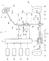
図1は実施例1の車両用ステアリング装置10を模式的に示している。車両用ステアリング装置10は、車幅方向にスライド可能な転舵軸31の両端から転舵力を取り出すようにしたエンドテイクオフ型ステアリング装置である。さらに、この車両用ステアリング装置10は、ステアリングホイール21に対して、転舵機構30を機械的に分離するとともに電気的には接続した方式の、いわゆるステア・バイ・ワイヤ式(steer-by-wire、略称「SBW」)のステアリング装置である。
A vehicle steering apparatus according to a first embodiment will be described with reference to FIGS. 1 and 2.
FIG. 1 schematically shows a
ステアリングホイール21に対して、転舵機構30を電気的に接続する構成は、ステアリングホイール21の操舵に基づく操舵情報に応じて転舵用アクチュエータ35が転舵用動力を発生し、この転舵用動力を転舵機構30に伝え、この転舵機構30によって左右の車輪32,32を転舵させるものである。
In the configuration in which the
以下、車両用ステアリング装置10(以下、単に「ステアリング装置10」という。)について詳しく説明する。ステアリング装置10は、操舵機構20と転舵機構30と制御部51とからなる。
Hereinafter, the vehicle steering device 10 (hereinafter simply referred to as “steering
操舵機構20は、運転者が手動操舵するステアリングホイール21と、このステアリングホイール21に連結された操舵軸22と、ステアリングホイール21の操舵に基づく操舵情報に応じた操舵反力を発生する反力モータ23と、操舵反力をステアリングホイール21に伝達する反力伝達機構24とからなる。
The
反力モータ23は電動モータからなる。反力伝達機構24は、反力モータ23のモータ軸に設けられたピニオン25と、このピニオン25に噛み合わされたギヤ26とからなる。操作反力は、ステアリングホイール21に対して回転方向に付加する操作抵抗である。
The
転舵機構30は、転舵軸31と、この転舵軸31の両端に左右の車輪32,32(例えば前輪)を連結するタイロッド33,33及びナックル34,34と、転舵軸31に転舵用動力を付加する転舵用アクチュエータ35とからなる。
The
転舵用アクチュエータ35は、転舵用動力を発生する転舵動力モータ36と、転舵用動力を転舵軸31に伝達する転舵動力伝達機構37とからなる。転舵動力モータ36が発生した転舵用動力は、転舵動力伝達機構37によって転舵軸31に伝達される。この結果、転舵軸31は車幅方向にスライドする。転舵動力モータ36は電動モータからなる。転舵動力モータ36のモータ軸36aは、転舵軸31を囲う中空軸である。転舵動力伝達機構37は、ボールねじからなる。このボールねじ37は、転舵軸31に形成されたねじ部37aと、ねじ部37aに組付けられたナット37bと、多数のボール37cとからなる。
なお、転舵動力伝達機構37は、ボールねじの構成に限定されるものではなく、例えばウォームギヤ機構やラックアンドピニオン機構であってもよい。
The turning
The steered
上述のように、転舵機構30は、ステアリングホイール21に電気的に接続されている。ステアリング装置10は、その他に、ステアリングホイール21に対して、転舵機構30を機械的に接続するための、機械的接続機構40を有している。機械的接続機構40は、第1回転軸41と第2回転軸42と連結機構43とからなる。
As described above, the
第1回転軸41は、自在軸継ぎ手44,44及び操舵軸22を介してステアリングホイール21に連結されている。ステアリングホイール21の操舵力は第1回転軸41に伝達される。
The first
第2回転軸42は、ラックアンドピニオン機構45を介して転舵軸31に連結されている。ラックアンドピニオン機構45は、転舵軸31に形成されたラック46と、第2回転軸42に形成されたピニオン47とからなる。転舵軸31がスライド作動するときの転舵力は、ラックアンドピニオン機構45から第2回転軸42に伝達される。この結果、転舵軸31の左右スライド作動に応じて、第2回転軸42が左右に回転する。
The second
連結機構43は、第1・第2回転軸41,42同士を、一定の相対的な回転角の範囲で互いに空転可能(空回り可能)に連結するものである。連結機構43の詳細については後述する。
The connecting
上記反力伝達機構24のギヤ26は、第1回転軸41又は操舵軸22に設けられる。この結果、反力モータ23が発生した操舵反力は、第1回転軸41又は操舵軸22を介してステアリングホイール21に伝達される。
The
上記制御部51は操舵角センサ52と転舵トルクセンサ53と第2回転軸角度センサ54から、それぞれ検出信号を受けるとともに、車両の走行速度を検出する車速センサ55、ヨー角速度(ヨー運動の角速度)を検出するヨーレートセンサ56、車両の加速度を検出する加速度センサ57、その他の各種センサ58からそれぞれ検出信号を受けて、反力モータ23及び転舵動力モータ36に制御信号を発するものである。
The
操舵角センサ52は、ステアリングホイール21の操舵角θsを検出するものであり、例えば、第1回転軸41又は操舵軸22の回転角を検出することによって、操舵角θsを得ることが可能である。転舵トルクセンサ53は、ステアリングホイール21の操舵トルクTsを検出するものであり、例えば、第1回転軸41又は操舵軸22のトルクを検出することによって、操舵トルクTsを得ることが可能である。第2回転軸角度センサ54は、第2回転軸42の回転角を検出するものである。
The
なお、操舵角センサ52が転舵トルクセンサ53を兼ねてもよい。また、操舵角センサ52や転舵トルクセンサ53については、反力モータ23に内蔵されているモータ軸回転角センサ(図示せず)によって兼ねることが可能である。このモータ軸回転角センサは、モータ軸の回転角を検出することによって、ロータの位相を検出するものである。
The
制御部51は、操舵角センサ52及び転舵トルクセンサ53の検出信号によって、ステアリングホイール21の操舵に基づく操舵情報を得ることができる。この操舵情報は、ステアリングホイール21の操舵角θs、操舵角速度Vs、操舵角加速度αs、操舵トルクTs及びこの操舵トルクTsの微分値ds(操舵トルクTsの変化度合いds)の、少なくとも1つである。操舵角速度Vs及び操舵角加速度αsについては、制御部51がステアリングホイール21の操舵角θsに基づいて演算することにより求められる。操舵トルクTsの微分値dsについては、制御部51がステアリングホイール21の操舵トルクTsに基づいて演算することにより求められる。
The
このように、操舵情報として、ステアリングホイール21の操舵角θs、操舵角速度Vs、操舵角加速度αs、操舵トルクTs及びこの操舵トルクの微分値dsの、少なくとも1つが採用される。このため、車両の開発・設計段階において、各車種に応じた最適な操舵情報を適宜選定することにより、各車種に応じた最適な車両用ステア・バイ・ワイヤ式ステアリング装置を提供することができる。 As described above, at least one of the steering angle θs, the steering angular velocity Vs, the steering angular acceleration αs, the steering torque Ts, and the differential value ds of the steering torque is adopted as the steering information. For this reason, an optimal vehicle steer-by-wire steering device according to each vehicle type can be provided by appropriately selecting optimal steering information according to each vehicle type at the vehicle development / design stage. .
さらに、制御部51は、反力モータ23を制御することによって、ステアリングホイール21の操舵に応じた操舵反力を自動的に設定し、操舵反力をステアリングホイール21に付加して、次の4つの制御をすることができる。
Furthermore, the
第1に、反力モータ23によってギヤ26を、ステアリングホイール21の操舵方向とは逆方向へ回転させた場合には、ステアリングホイール21の操舵力を反力モータ23の操舵反力によって打ち消す作用が働く。このため、ステアリングホイール21を操舵するときに、操舵反力分だけ大きい操舵力が必要となる。
First, when the
第2に、反力モータ23によってギヤ26を、ステアリングホイール21の操舵方向と同方向へ回転させた場合には、ステアリングホイール21の操舵力に反力モータ23の操舵反力を加える作用が働く。このため、ステアリングホイール21を操舵するときに、操舵反力分だけ小さい操舵力ですむ。
Second, when the
第3に、ステアリングホイール21を任意の角度で停止状態に保持させる場合には、それまでのステアリングホイール21の回転方向とは逆方向に、反力モータ23の操舵反力を調整しながらギヤ26を回転させることによって、保持力を発生させる。
Thirdly, when the
第4に、その後にステアリングホイール21を戻す場合には、ステアリングホイール21の中立位置までステアリングホイール21を自動的に戻す、いわゆるセルフアライニングトルクに相当する戻し力(操舵反力)が、反力モータ23からギヤ26に伝達する。
Fourth, when the
さらに、制御部51は、操舵情報に応じた操舵反力を発生する反力モータ23を利用して、多様な操舵制御を行うことが可能である。例えば、第1回転軸41の回転角が、第2回転軸42に対して一定の相対的な回転角の範囲から外れそうになった場合に、反力モータ23が発生する操舵反力を急増させる。運転者は、操舵反力が急増したことを認識したときに、ステアリングホイール21の操舵角θsを抑制(これ以上の切り増しを抑制)すればよい。
Furthermore, the
但し、運転者がステアリングホイール21を据え切り操舵、つまり車両の停止中におけるステアリングホイール21の操舵をする場合のように、転舵用アクチュエータ35が大きい転舵用動力を発生する場合には、第1回転軸41の回転角が、第2回転軸42に対して一定の相対的な回転角の範囲から外れそうになり得る。この場合には、第1回転軸41の回転角が、第2回転軸42に対して一定の相対的な回転角の範囲に達したことを検出し、ステアリングホイール21と転舵機構30との間を、機械的な経路によって接続させる。この結果、転舵用アクチュエータ35による転舵用動力に運転者の操舵力を付加した、複合的な力を転舵機構30に伝達して転舵作動をさせることができる。このようにすることで、転舵用アクチュエータ35が発生する転舵用動力を低減させることができる。この結果、転舵用アクチュエータ35を小型化することができる。
However, when the
さらに制御部51は、転舵動力モータ36を制御することによって、ステアリングホイール21の操舵角に対する車輪32,32の転舵角の角度比の特性、すなわち、操舵特性を自動的に設定することができる。言い換えると、上述のようにステアリングホイール21から転舵機構30を機械的に分離したので、ステアリングホイール21の操舵角と転舵用アクチュエータ35の動作量との対応関係を、機械的な制約を受けることなく設定することができる。この結果、操舵特性を車速、車両の旋回程度や加減速の有無等、車両の走行状態に応じて柔軟に設定することができる。従って、ステアリング装置10の設計の自由度を高めることができる。
Further, the
次に、機械的接続機構40の詳細を説明する。図2(a)は、ステアリングホイール21と機械的接続機構40の関係を示している。図2(b)は、ステアリングホイール21及び機械的接続機構40に対する車輪32,32の関係を示している。
Next, details of the
図1及び図2(a)に示すように、連結機構43は、第1回転軸41の一端に有している第1フランジ61と、第2回転軸42の一端に有している第2フランジ62と、第1・第2フランジ61,62のいずれか一方に有している連結バー63と、第1・第2フランジ61,62のいずれか他方に有している長孔64とからなる。第1・第2回転軸41,42は同一の軸線CL上に位置している。第1フランジ61と第2フランジ62は互いに対面し合うように位置している。なお、第1・第2フランジ61,62間に隙間を有するか否かについては任意であり、適宜設定すればよい。
As shown in FIGS. 1 and 2A, the
以下、第1フランジ61に連結バー63を有するとともに、第2フランジ62に長孔64を有した例で説明する。長孔64は、軸線CLを中心とした円弧状の長孔であり、軸線CLに沿って貫通している。この長孔64の左端をLeとし、右端をReとする。左端Leから右端Reまでの中央の点Neを「回転方向の基準点Ne」とする。基準点Neから左端Leまでの角度と、基準点Neから右端Reまでの角度は、共にθr1である。左端Leから右端Reまでの角度θr2は、θr1の2倍である。
Hereinafter, an example in which the
一方、連結バー63は、第1フランジ61から長孔64内へ延びている。このため、第1・第2回転軸41,42同士を、相対的に回転させたときに、連結バー63は長孔64の範囲内、つまり、左端Leから右端Reまでにわたって、空転可能(空回り可能)である。このように、連結機構43は、第1・第2回転軸41,42同士を、一定の相対的な回転角θr2の範囲で互いに空転可能に連結するものである。
On the other hand, the connecting
ここで、回転方向の基準点Neは、ステアリングホイール21の中立位置に一致する。ステアリングホイール21が中立位置に位置するときに、連結バー63は回転方向の基準点Neに位置する。左端Leから右端Reまでの角度θr2、つまり相対的な回転角θr2は、好ましくは360deg未満の値に設定される。より好ましくは、基準点Neから左右の端Le,Reまでの角度θr1は、50〜70degに設定される。
Here, the reference point Ne in the rotation direction coincides with the neutral position of the
実施例1の説明をまとめると、次の通りである。
実施例1では、ステアリングホイール21に連結された第1回転軸41と、転舵機構30に連結された第2回転軸42とを、連結機構43によって一定の相対的な回転角θr2の範囲で互いに空転可能に連結している。
The description of the first embodiment is summarized as follows.
In the first embodiment, the first
ここで、ステアリングホイール21と転舵機構30との間が、電気的な経路だけによって接続されている場合について考える。ステアリングホイール21を操舵すると、操舵角θsに応じて第1回転軸41が左右に回転する。一方、ステアリングホイール21の操舵に基づく操舵情報に応じて、転舵用アクチュエータ35が転舵用動力を発生し、この転舵用動力を転舵機構30に伝え、この転舵機構30によって車輪32,32を転舵させる。
Here, consider a case where the
一般に、転舵機構30によって車輪32,32を転舵させることが可能な最大転舵角β(図2(b)参照)は、予め設定されている。例えば、実施例1のように、ステアリング装置10にエンドテイクオフ型ステアリング装置を採用した場合には、転舵軸31のストロークがストッパによって規制されることにより、最大転舵角βが規制される。転舵機構30の作動に応じて第2回転軸42が左右に回転するので、この第2回転軸42の最大回転角は、転舵機構30によって車輪32,32を最大転舵角βだけ転舵する範囲に規制される。
In general, the maximum turning angle β (see FIG. 2B) at which the
第1回転軸41は、第2回転軸42に対して一定の相対的な回転角θr2の範囲でのみ、第2回転軸42の回転に影響を及ぼすことなく、自由に空転可能である。第2回転軸42に対する第1回転軸41の相対的な回転角は、第2回転軸42の最大回転角θr2の範囲内で、適宜設定すればよい。第1回転軸41の最大回転角は、第2回転軸42の最大回転角に一定の相対的な回転角θr2を加えた範囲内に収まる。つまり、第1回転軸41及びステアリングホイール21の最大回転角(最大操舵角)が規制される。
The
同様に、ステアリングホイールと転舵機構との間が、機械的接続機構40(機械的な経路)だけによって接続されている場合も、第1回転軸41及びステアリングホイール21の最大回転角が規制される。
Similarly, when the steering wheel and the steering mechanism are connected only by the mechanical connection mechanism 40 (mechanical path), the maximum rotation angles of the first
このように、電気的な接続経路と機械的な経路のどちらの経路においても、第1回転軸41及びステアリングホイール21の最大回転角が規制される。車両用ステア・バイ・ワイヤ式ステアリング装置10において、ステアリングホイール21の操舵角θsを容易に且つ確実に制限することができる。
Thus, the maximum rotation angle of the first
ところで、図2(a)に示すように、ステアリングホイール21には、例えば、エアバッグ装置71や図示せぬ電気部品が装着されている。ステアリングホイール21と共に回転可能なエアバッグ装置71と、このエアバッグ装置71に制御信号を発するために車体に固定されたエアバッグ制御部(図示せず)との間は、ケーブル72によって接続されている。このケーブル72は、ステアリングホイール21に装着されたケーブルリール73に巻かれている。ケーブルリール73が回転可能な回数には、ケーブル72の巻き数による制限がある。ステアリングホイール21の操舵角θs(回転回数)が無制限であると、ケーブルリール73やケーブル72に過大な負担がかかる。
By the way, as shown to Fig.2 (a), the
これに対して、実施例1では、上述のように、ステアリングホイール21の操舵角θsを容易に且つ確実に制限することができる。このため、ステアリングホイール21に装着されたケーブルリール73や、ケーブルリール73に巻かれているケーブル72に、過大な負担がかかることはない。
In contrast, in the first embodiment, as described above, the steering angle θs of the
実施例2の車両用ステアリング装置について説明する。図3は実施例2の機械的接続機構40Aの構成を示している。実施例2の車両用ステアリング装置10Aは、図2(a)に示す機械的接続機構40を、図3に示す機械的接続機構40Aに変更したことを特徴とし、他の構成については上記図1〜図2に示す構成と同じなので、説明を省略する。
A vehicle steering apparatus according to Embodiment 2 will be described. FIG. 3 shows the configuration of the
具体的には、実施例2の機械的接続機構40Aは、第1回転軸41と第2回転軸42と連結機構43Aとからなる。この連結機構43Aは、第1・第2回転軸41,42同士を、一定の相対的な回転角θr2の範囲で互いに空転可能に連結するものである。この連結機構43Aは、第1回転軸41の一端に有している嵌合軸部81と、第2回転軸42の一端に有している有底状の嵌合孔82と、第2回転軸42の一端に有している長孔83と、嵌合軸部81に有している連結バー84とからなる。嵌合軸部81は嵌合孔82に相対回転が可能に嵌合している。
Specifically, the
長孔83は、第2回転軸42の周方向に細長く、嵌合孔82に貫通している。この長孔83において、回転方向の基準点Neから左端Leまでの角度と、基準点Neから右端Reまでの角度は、共にθr1である。左端Leから右端Reまでの角度θr2は、θr1の2倍である。一方、連結バー84は、嵌合軸部81から長孔83内へ延びている。第1・第2回転軸41,42同士を、相対的に回転させたときに、連結バー84は長孔83の範囲内、つまり、左端Leから右端Reまでにわたって、空転可能である。
The
実施例2のステアリング装置10Aの作用、効果は上記実施例1のステアリング装置10と実質的に同じであり、説明を省略する。
The operation and effect of the
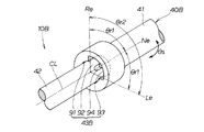
実施例3の車両用ステアリング装置について説明する。図4は実施例3の機械的接続機構40Bの構成を示している。実施例3の車両用ステアリング装置10Bは、図2(a)に示す機械的接続機構40を、図4に示す機械的接続機構40Bに変更したことを特徴とし、他の構成については上記図1〜図2に示す構成と同じなので、説明を省略する。
A vehicle steering apparatus according to Embodiment 3 will be described. FIG. 4 shows the configuration of the
具体的には、実施例3の機械的接続機構40Bは、第1回転軸41と第2回転軸42と連結機構43Bとからなる。この連結機構43Bは、第1・第2回転軸41,42同士を、一定の相対的な回転角θr2の範囲で互いに空転可能に連結するものである。この連結機構43Bは、第1回転軸41の一端に有している嵌合孔91と、第2回転軸42の一端に有している嵌合軸部92と、嵌合孔91の内周面に有している長溝93と、嵌合軸部92に有している連結バー94とからなる。嵌合軸部92は嵌合孔91に相対回転が可能に嵌合している。
Specifically, the
長溝93は、嵌合孔91の内周面に沿って細長い円弧状の溝であり、嵌合孔91に開放している。この長溝93において、回転方向の基準点Neから左端Leまでの角度と、基準点Neから右端Reまでの角度は、共にθr1である。左端Leから右端Reまでの角度θr2は、θr1の2倍である。一方、連結バー94は、嵌合軸部92から長溝93内へ延びている。第1・第2回転軸41,42同士を、相対的に回転させたときに、連結バー94は長溝93の範囲内、つまり、左端Leから右端Reまでにわたって、空転可能である。
The
実施例3のステアリング装置10Bの作用、効果は上記実施例1のステアリング装置10と実質的に同じであり、説明を省略する。
The operation and effect of the
実施例4の車両用ステアリング装置について説明する。図5は実施例4の機械的接続機構40Cの構成を示している。つまり、図5(a)は機械的接続機構40Cを分解した状態を示す。図5(b)は機械的接続機構40Cの組立途中を示す。図5(c)は機械的接続機構40Cの組立状態を示す。 A vehicle steering apparatus according to Embodiment 4 will be described. FIG. 5 shows a configuration of a mechanical connection mechanism 40C according to the fourth embodiment. That is, FIG. 5A shows a state where the mechanical connection mechanism 40C is disassembled. FIG. 5B shows an assembling process of the mechanical connection mechanism 40C. FIG. 5C shows an assembled state of the mechanical connection mechanism 40C.
実施例4の車両用ステアリング装置10Cは、図2(a)に示す機械的接続機構40を、図5(a)〜(c)に示す機械的接続機構40Cに変更したことを特徴とし、他の構成については上記図1〜図2に示す構成と同じなので、説明を省略する。
The
具体的には、実施例4の機械的接続機構40Cは、第1回転軸41と第2回転軸42と連結機構43Cとからなる。この連結機構43Cは、第1・第2回転軸41,42同士を、一定の相対的な回転角θr2の範囲で互いに空転可能に連結するものである。
Specifically, the mechanical connection mechanism 40C according to the fourth embodiment includes a
この連結機構43Cは、第1回転軸41の一端に有している嵌合軸部101と、第2回転軸42の一端に有している有底状の嵌合孔102とからなる。嵌合軸部101は、厚みthの扁平状に形成されている。嵌合軸部101の径Dtは第1回転軸41の径と同一である。嵌合孔102は扁平状の孔であって、最大径がDhで最小幅がWhに設定されている。嵌合孔102の最大径Dhは、嵌合軸部101の径Dtよりも若干大きい。嵌合孔102の最小幅Whは、嵌合軸部101の厚みthよりも大きい。
The
嵌合軸部101は嵌合孔102に嵌合している。最小幅Whが嵌合軸部101の厚みthよりも大きい分だけ、間に隙間を有する。この隙間の分だけ、嵌合軸部101は嵌合孔102に相対回転が可能である。つまり、嵌合軸部101の扁平面101aが嵌合孔102の扁平面102aに当たるまで、嵌合軸部101は嵌合孔102に相対回転が可能である。
The
嵌合孔102の扁平面102aに対して嵌合軸部101の扁平面101aが平行であるときに、第2回転軸42に対して第1回転軸41が回転方向の基準点Neにある。その後、第2回転軸42に対して第1回転軸41を左へ回したときに、扁平面101a,102a同士が当たった点Leは、左回転限界点である。左回転限界点Leは、図2(a)に示す実施例1の長孔64の左端Leに相当する。一方、第2回転軸42に対して第1回転軸41を右へ回したときに、扁平面101a,102a同士が当たった点Reは、右回転限界点である。右回転限界点Reは、図2(a)に示す実施例1の長孔64の右端Reに相当する。
When the
基準点Neから左回転限界点Leまでの角度と、基準点Neから右回転限界点Reまでの角度は、共にθr1である。左回転限界点Leから右回転限界点Reまでの角度θr2は、θr1の2倍である。 The angle from the reference point Ne to the left rotation limit point Le and the angle from the reference point Ne to the right rotation limit point Re are both θr1. The angle θr2 from the left rotation limit point Le to the right rotation limit point Re is twice as large as θr1.
第1・第2回転軸41,42同士を、相対的に回転させたときに、嵌合軸部101は嵌合孔102の範囲内、つまり、左端Leから右端Reまでにわたって、空転可能である。
When the first and second
実施例4のステアリング装置10Cの作用、効果は上記実施例1のステアリング装置10と実質的に同じであり、説明を省略する。
The operation and effect of the
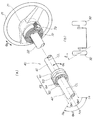
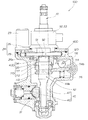
実施例5に係る車両用ステアリング装置について、図6〜図10に基づき説明する。図6は実施例5の車両用ステアリング装置10Dを模式的に示している。図7は図6に示された反力モータ23、反力伝達機構24、機械的接続機構40D及びクラッチ110の組立状態を示している。
A vehicle steering apparatus according to a fifth embodiment will be described with reference to FIGS. FIG. 6 schematically shows a
図6及び図7に示すように、実施例5の車両用ステアリング装置10Dは、機械的接続機構40Dとクラッチ110とを有していることを特徴とし、他の構成については上記図1〜図2に示す構成と同じなので、説明を省略する。なお、反力伝達機構24、転舵軸31、第2回転軸42、ラックアンドピニオン機構45及びクラッチ110は、ハウジング120に収納されている。
As shown in FIGS. 6 and 7, the
図6及び図7に示す機械的接続機構40Dは、図2(a)に示す機械的接続機構40を変更したものである。つまり、実施例5の機械的接続機構40Dは、第1回転軸41と第2回転軸42と連結機構43Dとからなる。
The
この連結機構43Dは、上記図4に示す連結機構43Bと実質的に同じ構成であり、嵌合孔91と嵌合軸部92と長溝93と連結バー94の組み合わせからなる。嵌合孔91は、ギヤ26のボス26aに形成されている。ボス26aは、第1回転軸41に取り付けられている。嵌合軸部92は、第2回転軸42の一端に有している。長溝93は、嵌合孔91の内周面に有している。連結バー94は、嵌合軸部92に有している。
The
図7〜図9に示すように、クラッチ110は、円錐状のドグクラッチからなる。詳しく述べると、クラッチ110は、第2回転軸42を中心とする雌テーパ状の雌クラッチ部111と、第2回転軸42を中心とする雄テーパ状の雄クラッチ部112とからなる。雌クラッチ部111は、ギヤ26のボス26aの一端に形成されたテーパ面からなり、クラッチ歯を有する。雄クラッチ部112は、クラッチ用シフター113の一端に形成されたテーパ面からなり、クラッチ歯を有する。各クラッチ歯同士が噛み合ったときにクラッチオンとなる。
As shown in FIGS. 7 to 9, the clutch 110 is formed of a conical dog clutch. More specifically, the clutch 110 includes a female tapered female
クラッチ用シフター113は、第2回転軸42に対して相対回転が規制されるとともに、軸方向への相対スライドが可能に取り付けられている。このクラッチ用シフター113は、外周面に全周にわたって形成された円周溝113aを有している。この円周溝113aには、フォーク状のシフトフォーク114の先端部114a,114aが嵌合している。シフトフォーク114は、第2回転軸42に対して略直交する方向へ延びたスイング部材であって、基端部114bがハウジング120にスイング可能に取り付けられている。シフトフォーク114のスイング方向は、第2回転軸42の軸方向である。
The
シフトフォーク114は、圧縮コイルばね115(付勢部材)によって付勢されている。圧縮コイルばね115の付勢方向は、雌クラッチ部111に対して雄クラッチ部112を噛み合わせる方向へ、クラッチ用シフター113をスライドさせる方向である。
The
図10(a)は、クラッチオフ(off)状態におけるシフトフォーク114を示している。図10(b)は、クラッチオン(on)状態におけるシフトフォーク114を示している。シフトフォーク114は、偏心カム116によって圧縮コイルばね115側に押し付けられている。つまり、偏心カム116は、圧縮コイルばね115とは反対側の面114cに臨むように位置している。
FIG. 10A shows the
図7〜図10(a)に示すように、偏心カム116は、円盤状のカム本体116aと、カム本体116aの回転軸116bと、カム本体116aの外周面から外方へ突出した係止凸部116cとからなる。
As shown in FIGS. 7 to 10A, the
図10(a)に示すように、カム本体116aは側面視において真円に形成されている。カム本体116aの外周面は、シフトフォーク114の平坦な接触面114cに、接点Pcで接触している。接点Pcにおいて、接触面114cに直交する直線を垂直線Xoとし、接触面114cに平行な直線を水平線Yoとする。垂直線Xoに対して水平線Yoは直交している。カム本体116aの中心Pcは、垂直線Xoと水平線Yoとの交点に有している。
As shown in FIG. 10A, the
偏心カム116は、回転軸116bを回転中心として回転する。回転軸116bは、カム本体116aの中心Pcから径外方へ所定のオフセット距離Zcだけ偏心しており、ハウジング120(図7参照)に回転可能に支持されている。カム本体116aの中心Pcと回転軸116bとを通る直線Qcは、接触面114cに対して傾いている。オフセット距離Zcについては、クラッチ110(図7参照)をオン・オフ切り替えするのに必要な、シフトフォーク114のスイング量に基づいて設定される。
The
詳しく述べると、図10(a)に示すクラッチオフ(off)状態において、回転軸116bを軸方向から見る。回転軸116bの中心は、垂直線Xoに対してシフトフォーク114の基端部114b側へ所定の第1オフセット距離Xcだけ偏心し、しかも、水平線Yo対して接触面114cとは反対側へ所定の第2オフセット距離Ycだけ偏心している。一方、係止凸部116cの位置と、この係止凸部116cを係止させるためのストッパ117の位置は、垂直線Xo対して回転軸116bとは反対側に偏心している。
More specifically, the
クラッチオフ(off)状態においては、制御部51は、電動モータ118に駆動指令を発し続けている。電動モータ118は小電流が供給されて、回転軸116bを図反時計方向(矢印RL)へ回転駆動し続ける。このため、偏心カム116は、係止凸部116cがストッパ117に係止した状態で、停止している。この場合、偏心カム116は圧縮コイルばね115の付勢力fcに抗してシフトフォーク114を押し付けることによって、クラッチ用シフター113を押し下げた状態を維持する。クラッチ110は通常時のオフ状態(断状態)を維持する。
In the clutch-off (off) state, the
ところで、上述のように、オフセット距離Zcについては、シフトフォーク114の必要スイング量に基づいて設定されている。このオフセット距離Zcを確保するのに、図10(a)に示すように、垂直線Xoに対して第1オフセット距離Xcだけ偏心するとともに、水平線Yoに対して第2オフセット距離Ycだけ偏心している。つまり、回転軸116bは、中心Pcを通る垂直線Xo及び水平線Yoに対して偏心している。
By the way, as described above, the offset distance Zc is set based on the required swing amount of the
圧縮コイルばね115の付勢力fcは、接点Pcにおいて、シフトフォーク114の接触面114cからカム本体116aの外周面に作用する。この外周面に作用する付勢力fcの作用方向は、垂直線Xoの線方向である。付勢力fcに基づいて、回転軸116bに作用するトルク(付勢トルク)は第1オフセット距離Xcに比例する。本実施例においては、オフセット距離Zcを確保するのに、垂直線Xo及び水平線Yoに対して回転軸116bを偏心させたので、その分だけ、第1オフセット距離Xcを小さくすることができ、この結果、付勢トルクを小さくすることができる。付勢トルクが小さくなった分、電動モータ118の駆動トルクを低減させることができる。このため、電動モータ118に供給する電流を減少させることができるとともに、電動モータ118を小型化できる。
The urging force fc of the
その後、制御部51は、図6に示すステアリングホイール21から転舵機構30までの、電気的な接続経路を解除したときには、電動モータ118に停止指令を発する。電動モータ118が停止すると、圧縮コイルばね115の付勢力fcによって、シフトフォーク114はカム本体116a側にスイングする。カム本体116aは、シフトフォーク114に押され、回転軸116bを回転中心として図時計方向(矢印RR)へ回転し、図10(b)に示す状態となる。つまり、接触面114cが回転軸116bに最も接近した状態となる。このときに、カム本体116aの中心Pcと回転軸116bとを通る直線Qcは、接触面114cに直交する。
Thereafter, when the electrical connection path from the
このように、電動モータ118が停止することで、シフトフォーク114がスイングして、図7に示すクラッチ用シフター113をスライドさせる。この結果、雌クラッチ部111に対して雄クラッチ部112が噛み合わせられることにより、クラッチ110はオン状態(結合状態)になる。クラッチ110が通常時のオフ状態からオン状態に反転することによって、第1・第2回転軸41,42同士を強制的に連結状態にする。このため、連結機構43Dの連結状態にかかわらず、第1・第2回転軸41,42同士は強制的に連結される。
As described above, when the
その後、制御部51から電動モータ118に回転指令を発した場合には、電動モータ118が回転するので、クラッチ110は再び通常時のオフ状態(断状態)に復帰する。
Thereafter, when a rotation command is issued from the
クラッチ110は、円錐状のドグクラッチの他に、円錐状の摩擦クラッチであってもよい。このように、円錐状のドグクラッチ又は円錐状の摩擦クラッチという比較的簡単な構成によって、クラッチ110を構成することができる。 The clutch 110 may be a conical friction clutch in addition to the conical dog clutch. Thus, the clutch 110 can be configured with a relatively simple configuration such as a conical dog clutch or a conical friction clutch.
ところで、第1・第2回転軸41,42同士の相対的な回転角は、連結機構43Dによって、回転角θr2(図4参照)の範囲に規制されている。例えば、連結バー94に長溝93の左端Le(図4参照)が当たった状態において、連結バー94に対し長溝93が更に左へ相対的な回転をすることは、規制される。つまり、第2回転軸42に対する第1回転軸41の相対的な左回転は規制される。このため、第1回転軸41に左方向の大きい操舵力が発生することによって、相対的な回転角が過大になろうとしても、第1回転軸41からの大きい操舵力は、連結機構43Dを介して第2回転軸42に伝達される。従って、クラッチ110に所定以上の大きい操舵力が作用することはない。つまり、クラッチ110によって伝達可能な最大伝達力(最大伝達トルク)を低減することができる。
By the way, the relative rotation angle between the first and
このことは、長溝93の右端Re(図4参照)が連結バー94に当たった状態において、連結バー94に対し長溝93が更に右へ相対的な回転をする場合も同様である。
このように、クラッチ110の伝達可能な最大伝達力を下げることによって、クラッチ110を小型化することができる。その効果は、円錐状の摩擦クラッチを採用した場合に、特に顕著である。
The same applies to the case where the
Thus, the clutch 110 can be reduced in size by lowering the maximum transmission force that can be transmitted by the clutch 110. The effect is particularly remarkable when a conical friction clutch is employed.
実施例5によれば、クラッチ110は、図6に示す「電気的に接続する構成」が解除されたときに、オフ状態からオン状態に反転する。この結果、ステアリングホイール21と転舵機構30との間は、機械的な経路によって接続される。従って、何らかの要因によって、電気的な接続経路が解除されたときには、ステアリングホイール21と転舵機構30との間の経路を、自動的にクラッチ110によって、機械的な経路(機械的接続機構40D)に確実に且つ迅速に切り替えることができる。
According to the fifth embodiment, the clutch 110 reverses from the off state to the on state when the “electrically connected configuration” shown in FIG. 6 is released. As a result, the
実施例6に係る車両用ステアリング装置について、図11及び図12に基づき説明する。図11及び図12に示すように、実施例6の車両用ステアリング装置10Eは、機械的接続機構40Eとクラッチ140とを有していることを特徴とし、他の構成については上記図6に示す構成と同じなので、説明を省略する。
A vehicle steering apparatus according to Embodiment 6 will be described with reference to FIGS. 11 and 12. As shown in FIGS. 11 and 12, the
実施例6の機械的接続機構40Eは、第1回転軸41と第2回転軸42と連結機構43Eとからなる。この連結機構43Eは、第1・第2回転軸41,42同士を、一定の相対的な回転角θr2の範囲で互いに空転可能に連結するものである。この連結機構43Eは、第1回転軸41の一端に有している嵌合軸部131と、第2回転軸42の一端に有している有底状の嵌合孔132と、嵌合軸部131に有している連結バー133と、スライダ134と、スライダ134に有しているカム孔135とからなる。嵌合軸部131は嵌合孔132に相対回転が可能に嵌合している。
The
スライダ134は、第1・第2回転軸41,42に対して同心に位置した筒状の部材であって、第1・第2回転軸41,42同士の嵌合部分を貫通している。このスライダ134は、第2回転軸42に対して、相対回転が規制されるとともに、軸方向への相対スライドが可能に取り付けられている(例えばセレーション結合)。また、スライダ134は、第1回転軸41に対しては、相対回転と軸方向への相対スライドの両方共に可能である。スライダ134には、クラッチ用シフター113が一体的に設けられている。
The
クラッチ用シフター113とシフトフォーク114と偏心カム116とストッパ117と電動モータ118(図8参照)については、上記図7〜図10に示す実施例6と実質的に同じ構成なので、説明を省略する。
The
シフトフォーク114は、ねじりコイルばね115E(付勢部材)によって付勢されている。ねじりコイルばね115Eは、上記図7〜図10に示す圧縮コイルばね115の代わりに用いるものである。ねじりコイルばね115Eの付勢方向は、クラッチ140がオンになる方向へ、クラッチ用シフター113をスライドさせる方向である。
The
図12(a)は機械的接続機構40E及びクラッチ140の分解構成を示している。図12(b)は機械的接続機構40E及びクラッチ140の組立構成(クラッチ140のオン状態)を示している。図12(c)はクラッチ140のオフ状態を示している。
FIG. 12A shows an exploded configuration of the
図12(a)〜(b)に示すように、スライダ134を外周面側から見たときに、カム孔135は略三角形状に形成されるとともに、スライダ134に対して内外貫通している。略三角形状のカム孔135は、第1回転軸41側の面135aを底辺とし、第2回転軸側を頂点とするように上下逆向きに位置し、更に頂点に係止凹部135bを有している。
As shown in FIGS. 12A and 12B, when the
以下、第1回転軸41側の面135aのことを、底辺135a又は底面135aという。底辺135aは、第1回転軸41に対して直交する水平な面である。係止凹部135bの幅(周方向の幅)は、連結バー133が微小の隙間を有して嵌合可能な大きさに設定されている。カム孔135において、底辺135aの両端と係止凹部135bとの間は、左右一対の斜面(斜辺)135c,135cとなる。左右一対の斜面135c,135cは、係止凹部135bへ向かって先細りとなるテーパ状である。
Hereinafter, the
図12(a)〜(b)に示すように、カム孔135の底辺135aにおいて、回転方向の基準点Neから左端Leまでの角度と、基準点Neから右端Reまでの角度は、共にθr1である。左端Leから右端Reまでの角度θr2は、θr1の2倍である。一方、連結バー133は、嵌合軸部131からカム孔135内へ延びている。第1・第2回転軸41,42同士を、相対的に回転させたときに、連結バー133はカム孔135の範囲内、つまり、左端Leから右端Reまでにわたって、空転可能である。
As shown in FIGS. 12A to 12B, on the
図12(c)に示すように、クラッチ140は、連結バー133と係止凹部135bとからなる。このクラッチ140は、図11及び図12(b)に示すように、連結バー133に対して係止凹部135bが嵌合していない状態で、通常時のオフ状態(断状態)を維持する。
As shown in FIG. 12 (c), the clutch 140 includes a connecting
その後、図10に示す制御部51から電動モータ118に停止指令を発することによって、電動モータ118は停止する。このため、シフトフォーク114は、図11に示すクラッチ用シフター113を介してスライダ134を第1回転軸41側にスライドさせる。この場合、カム孔135は連結バー133によって案内される。スライダ134がスライドすることに伴い、連結バー133とカム孔135との間の空転範囲が狭まり、最後には、連結バー133に対して係止凹部135bが嵌合する。この結果、クラッチ140はオン状態(結合状態)になる。クラッチ140が通常時のオフ状態からオン状態に反転することによって、第1・第2回転軸41,42同士を強制的に連結状態にする。
Thereafter, the
その後、制御部51から電動モータ118に回転指令を発した場合には、電動モータ118が回転するので、クラッチ140は再び通常時のオフ状態(断状態)に復帰する。
Thereafter, when a rotation command is issued from the
実施例6によれば、カム孔135の一部である係止凹部135bと、連結バー133とによって、クラッチ140を構成している。連結機構43Eにクラッチ140を組込んだ、つまり連結機構43Eがクラッチ140を兼ねている。このため、クラッチ140の構成を簡単な構成にすることができるとともに、車両用ステアリング装置10Eを小型にすることができる。
According to the sixth embodiment, the clutch 140 is configured by the locking
実施例7に係る車両用ステアリング装置について、図13に基づき説明する。図13に示すように、実施例7の車両用ステアリング装置10Fは、機械的接続機構40Fとクラッチ140とを有していることを特徴とし、他の構成については上記図11及び図12示す構成と同じなので、説明を省略する。
A vehicle steering apparatus according to Embodiment 7 will be described with reference to FIG. As shown in FIG. 13, the
実施例7の機械的接続機構40Fは、上記図12に示す実施例6の斜面135c,135cを、図13に示す斜面135cF,135cFに変更したことを特徴とする。この斜面135cF,135cFは、実施例6の斜面135c,135cを階段状(凹凸状)に形成したものである。
The
上記図12に示す斜面135c,135cは、単なる傾斜面であった。このため、スライダ134が第1回転軸41へ向かってスライドしているときに、操舵力が第1回転軸41から連結バー133を介して斜面135cに作用した場合には、斜面135cの傾斜角の分だけ、操舵力が回転方向と軸方向とに分かれる(分力になる)。軸方向の分力は、スライダ134を逆方向へ戻す作用をする。
The
これに対し、実施例7では、斜面135cF,135cFが階段状に形成されているので、軸方向への分力の発生を極力防ぐことができる。 On the other hand, in Example 7, since the slopes 135cF and 135cF are formed in a step shape, the generation of the component force in the axial direction can be prevented as much as possible.
なお、本発明では、車両用ステアリング装置10,10A〜10Fは、車両の自動運転制御などと組み合わせて制御することも可能である。
In the present invention, the
本発明の車両用ステアリング装置10,10A〜10Fは、乗用車の操舵機構に用いるのに好適である。
The
10,10A〜10F…車両用ステアリング装置、20…操舵機構、21…ステアリングホイール、23…反力モータ、24…反力伝達機構、30…転舵機構、32…車輪、35…転舵用アクチュエータ、40,40A〜41F…機械的に接続する構成(機械的接続機構)、41…第1回転軸、42…第2回転軸、43,43A〜43F…連結機構、110,140…クラッチ、ds…操舵トルクの微分値、Ts…操舵トルク、Vs…操舵角速度、αs…操舵角加速度、θr2…一定の相対的な回転角、θs…操舵角。
DESCRIPTION OF
Claims (6)
前記ステアリングホイールに連結された第1回転軸と、前記転舵機構に連結された第2回転軸と、これら第1・第2回転軸同士を一定の相対的な回転角の範囲で互いに空転可能に連結する連結機構とを有し、
前記連結機構の一部は、前記第1回転軸と一体回転し、前記連結機構の他部は、前記第2回転軸と一体回転し、前記一定の相対的な回転角の範囲を超えることにより、前記連結機構の一部と前記連結機構の他部とが接触し、前記第1回転軸と前記第2回転軸とが一体回転し、
前記連結機構の一部は孔であると共に、前記連結機構の他部は前記孔に係合する突起であり、
前記孔は、略三角形であり、前記第1回転軸と前記第2回転軸とが、軸方向を基準として相対的に移動可能に設けられ、
前記孔と前記突起とによってクラッチ機構を構成することを特徴とした車両用ステアリング装置。 The steering mechanism is mechanically separated and electrically connected to the steering wheel, and this electrically connected configuration is a steering actuator according to steering information based on steering of the steering wheel. In the vehicle steering device that generates the power for turning, transmits the power for turning to the turning mechanism, and turns the wheels by the turning mechanism.
The first rotating shaft connected to the steering wheel, the second rotating shaft connected to the steering mechanism, and the first and second rotating shafts can idle with respect to each other within a range of a certain relative rotation angle. And a connecting mechanism for connecting to
A part of the connection mechanism rotates integrally with the first rotation shaft, and the other part of the connection mechanism rotates integrally with the second rotation shaft, and exceeds the range of the fixed relative rotation angle. , A part of the coupling mechanism and the other part of the coupling mechanism are in contact with each other, the first rotating shaft and the second rotating shaft rotate integrally ,
A part of the coupling mechanism is a hole, and the other part of the coupling mechanism is a protrusion that engages with the hole.
The hole is substantially triangular, and the first rotating shaft and the second rotating shaft are provided so as to be relatively movable with respect to an axial direction.
A vehicle steering apparatus, wherein the hole and the protrusion constitute a clutch mechanism .
このクラッチは、通常はオフ状態にあって、オン状態に反転したときには前記連結機構の連結状態にかかわらず、前記第1・第2回転軸同士を強制的に連結状態に切り替える構成であることを特徴とした請求項1から請求項4までのいずれか1項記載の車両用ステアリング装置。 A clutch, and
This clutch is normally in an off state, and when reversed to an on state, the clutch is configured to forcibly switch the first and second rotating shafts to a connected state regardless of the connected state of the connecting mechanism. The vehicle steering apparatus according to any one of claims 1 to 4 , wherein the vehicle steering apparatus is characterized.
Priority Applications (3)
| Application Number | Priority Date | Filing Date | Title |
|---|---|---|---|
| JP2009274545A JP5100740B2 (en) | 2009-12-02 | 2009-12-02 | Vehicle steering device |
| EP10193199.6A EP2330012B1 (en) | 2009-12-02 | 2010-11-30 | Vehicular steering apparatus |
| US12/957,589 US8640816B2 (en) | 2009-12-02 | 2010-12-01 | Vehicular steering apparatus |
Applications Claiming Priority (1)
| Application Number | Priority Date | Filing Date | Title |
|---|---|---|---|
| JP2009274545A JP5100740B2 (en) | 2009-12-02 | 2009-12-02 | Vehicle steering device |
Publications (2)
| Publication Number | Publication Date |
|---|---|
| JP2011116214A JP2011116214A (en) | 2011-06-16 |
| JP5100740B2 true JP5100740B2 (en) | 2012-12-19 |
Family
ID=43533312
Family Applications (1)
| Application Number | Title | Priority Date | Filing Date |
|---|---|---|---|
| JP2009274545A Expired - Fee Related JP5100740B2 (en) | 2009-12-02 | 2009-12-02 | Vehicle steering device |
Country Status (3)
| Country | Link |
|---|---|
| US (1) | US8640816B2 (en) |
| EP (1) | EP2330012B1 (en) |
| JP (1) | JP5100740B2 (en) |
Families Citing this family (26)
| Publication number | Priority date | Publication date | Assignee | Title |
|---|---|---|---|---|
| JP5241016B2 (en) * | 2009-01-29 | 2013-07-17 | 矢崎総業株式会社 | Rotating connector |
| JP2014024405A (en) * | 2012-07-25 | 2014-02-06 | Jtekt Corp | Steering apparatus |
| JP5945783B2 (en) * | 2012-09-13 | 2016-07-05 | 日本発條株式会社 | Ship helm equipment |
| US20150090519A1 (en) * | 2013-09-30 | 2015-04-02 | Ford Global Technologies, Llc | Semi-decoupled steering system |
| JP5903091B2 (en) * | 2013-12-24 | 2016-04-13 | 本田技研工業株式会社 | Vehicle steering system |
| US9199667B2 (en) * | 2014-03-14 | 2015-12-01 | Mitsubishi Electric Research Laboratories, Inc. | System and method for semi-autonomous driving of vehicles |
| CN103821834B (en) * | 2014-03-20 | 2016-06-08 | 重庆大学 | A kind of wireline ring resilient coupling |
| JP2015189346A (en) * | 2014-03-28 | 2015-11-02 | Ntn株式会社 | Unit for vehicle steering system |
| KR101970979B1 (en) * | 2014-04-16 | 2019-04-23 | 주식회사 만도 | Safety apparatus for Steer-By-Wire |
| JP6297644B2 (en) * | 2016-09-06 | 2018-03-20 | Ntn株式会社 | Rotation transmission device |
| JP6716401B2 (en) * | 2016-09-07 | 2020-07-01 | Ntn株式会社 | Rotation transmission device |
| WO2018047846A1 (en) * | 2016-09-06 | 2018-03-15 | Ntn株式会社 | Rotation transmission device |
| JP6838533B2 (en) * | 2017-09-11 | 2021-03-03 | 株式会社デンソー | Shift range controller |
| DE112018007476B4 (en) * | 2018-06-12 | 2021-06-10 | Showa Corporation | Steering angle limiting device |
| KR102634449B1 (en) * | 2018-10-25 | 2024-02-06 | 현대자동차주식회사 | Apparatus for limitted steering angle in steer-by-wire system |
| JP7155877B2 (en) * | 2018-10-30 | 2022-10-19 | 株式会社ジェイテクト | vehicle steering system |
| DE102018132172A1 (en) * | 2018-12-13 | 2020-06-18 | Trw Automotive Gmbh | Steer-by-wire steering system |
| DE102019102069A1 (en) | 2019-01-28 | 2020-07-30 | Bayerische Motoren Werke Aktiengesellschaft | Switchable clutch for a steer-by-wire steering system, steer-by-wire steering system, method for operation and vehicle |
| JP2020131958A (en) * | 2019-02-20 | 2020-08-31 | トヨタ自動車株式会社 | Steering device |
| DE102019204913A1 (en) * | 2019-04-05 | 2020-10-08 | Zf Friedrichshafen Ag | Method and device for operating a steering system of a motor vehicle, as well as a control device and steering system |
| KR102111294B1 (en) * | 2019-05-15 | 2020-05-15 | 주식회사 만도 | Steer-by-wire type power steering apparatus |
| CN112706828B (en) * | 2019-10-25 | 2022-08-09 | 比亚迪股份有限公司 | Clutch mechanism, steering system and automobile |
| CN112706830B (en) * | 2019-10-25 | 2022-11-11 | 比亚迪股份有限公司 | Clutch mechanism, steering system, decoupling control method of steering system and automobile |
| KR102786792B1 (en) * | 2020-08-25 | 2025-03-31 | 에이치엘만도 주식회사 | Steer-by-wire type steering apparatus |
| KR102548148B1 (en) * | 2021-08-17 | 2023-06-27 | 에이치엘만도 주식회사 | Power steering apparatus |
| WO2025032889A1 (en) * | 2023-08-07 | 2025-02-13 | Nskステアリング&コントロール株式会社 | Vehicle steering device |
Family Cites Families (16)
| Publication number | Priority date | Publication date | Assignee | Title |
|---|---|---|---|---|
| JP2970125B2 (en) * | 1990-12-25 | 1999-11-02 | 株式会社デンソー | Front wheel steering device |
| JPH08175403A (en) * | 1994-12-21 | 1996-07-09 | Honda Motor Co Ltd | Unit type electric power steering device |
| DE19926534A1 (en) * | 1999-06-10 | 2000-12-14 | Mercedes Benz Lenkungen Gmbh | Coupling for a mechanical emergency running function in motor vehicle steering incorporates an operating device to be worked by one person with a steering wheel, a controller and adjusters for a wheel angle actuating drive |
| JP3869981B2 (en) * | 1999-09-17 | 2007-01-17 | 株式会社ジェイテクト | Vehicle steering system |
| JP2004351975A (en) * | 2003-05-27 | 2004-12-16 | Ntn Corp | Fail-safe mechanism of steer-by-wire system and steer-by-wire system |
| JP2005178460A (en) * | 2003-12-17 | 2005-07-07 | Koyo Seiko Co Ltd | Vehicle steering system |
| JP2005178461A (en) * | 2003-12-17 | 2005-07-07 | Koyo Seiko Co Ltd | Vehicle steering system |
| JP4466197B2 (en) * | 2004-05-24 | 2010-05-26 | 日産自動車株式会社 | Vehicle steering system |
| JP4613609B2 (en) * | 2004-12-24 | 2011-01-19 | 日産自動車株式会社 | Vehicle steering system |
| JP4622837B2 (en) * | 2005-12-09 | 2011-02-02 | トヨタ自動車株式会社 | Vehicle steering device |
| JP4696919B2 (en) * | 2006-01-11 | 2011-06-08 | トヨタ自動車株式会社 | Vehicle steering device |
| JP4525621B2 (en) * | 2006-03-14 | 2010-08-18 | トヨタ自動車株式会社 | Vehicle steering device |
| JP4785763B2 (en) | 2007-02-02 | 2011-10-05 | 本田技研工業株式会社 | Vehicle steering system |
| JP2008195188A (en) * | 2007-02-13 | 2008-08-28 | Honda Motor Co Ltd | Vehicle steering system |
| JP4972424B2 (en) | 2007-02-13 | 2012-07-11 | 本田技研工業株式会社 | Vehicle steering system |
| JP2009113667A (en) * | 2007-11-07 | 2009-05-28 | Toyota Motor Corp | Vehicle steering device |
-
2009
- 2009-12-02 JP JP2009274545A patent/JP5100740B2/en not_active Expired - Fee Related
-
2010
- 2010-11-30 EP EP10193199.6A patent/EP2330012B1/en not_active Not-in-force
- 2010-12-01 US US12/957,589 patent/US8640816B2/en not_active Expired - Fee Related
Also Published As
| Publication number | Publication date |
|---|---|
| US20110127104A1 (en) | 2011-06-02 |
| EP2330012B1 (en) | 2013-10-23 |
| US8640816B2 (en) | 2014-02-04 |
| EP2330012A1 (en) | 2011-06-08 |
| JP2011116214A (en) | 2011-06-16 |
Similar Documents
| Publication | Publication Date | Title |
|---|---|---|
| JP5100740B2 (en) | Vehicle steering device | |
| JP6393858B1 (en) | Rudder angle regulating device | |
| CN103318253A (en) | Vehicle steering system | |
| JP2012056410A (en) | Steering device for vehicle | |
| JP2008168651A (en) | Clutch and vehicle steering apparatus using the clutch | |
| JP2012106720A (en) | Vehicle steering device | |
| JP4811595B2 (en) | Vehicle steering system | |
| JP2007153003A (en) | Vehicle steering system | |
| JP2010177039A (en) | Rotary connector | |
| US5248009A (en) | Vehicle rear wheels steering apparatus | |
| JP4654532B2 (en) | Joint structure, reduction mechanism and steering assist device using the same | |
| JP5262592B2 (en) | Steering force transmission device for vehicle | |
| KR20230021932A (en) | Steer-By-Wire Type Steering Apparatus | |
| JP4883164B2 (en) | Joint structure, reduction mechanism and steering assist device using the same | |
| JP4104346B2 (en) | Vehicle rear wheel steering device | |
| WO2019207708A1 (en) | Vehicle steering device | |
| JP2000255436A (en) | Steering gear | |
| JP2020185970A (en) | Steering device | |
| US20240383521A1 (en) | Steer-by-wire steering device | |
| JP2020069883A (en) | Steering angle regulation device | |
| JP3434578B2 (en) | Electric rear wheel steering system | |
| JP5359520B2 (en) | Steering device | |
| JP6596613B1 (en) | Steer-by-wire steering device and vehicle | |
| JP5133844B2 (en) | Steering force transmission device for vehicle | |
| WO2024257282A1 (en) | Rotation transmission device |
Legal Events
| Date | Code | Title | Description |
|---|---|---|---|
| A621 | Written request for application examination |
Free format text: JAPANESE INTERMEDIATE CODE: A621 Effective date: 20110801 |
|
| A977 | Report on retrieval |
Free format text: JAPANESE INTERMEDIATE CODE: A971007 Effective date: 20111013 |
|
| A131 | Notification of reasons for refusal |
Free format text: JAPANESE INTERMEDIATE CODE: A131 Effective date: 20111101 |
|
| A521 | Written amendment |
Free format text: JAPANESE INTERMEDIATE CODE: A523 Effective date: 20111228 |
|
| A131 | Notification of reasons for refusal |
Free format text: JAPANESE INTERMEDIATE CODE: A131 Effective date: 20120626 |
|
| A521 | Written amendment |
Free format text: JAPANESE INTERMEDIATE CODE: A523 Effective date: 20120822 |
|
| TRDD | Decision of grant or rejection written | ||
| A01 | Written decision to grant a patent or to grant a registration (utility model) |
Free format text: JAPANESE INTERMEDIATE CODE: A01 Effective date: 20120918 |
|
| A01 | Written decision to grant a patent or to grant a registration (utility model) |
Free format text: JAPANESE INTERMEDIATE CODE: A01 |
|
| A61 | First payment of annual fees (during grant procedure) |
Free format text: JAPANESE INTERMEDIATE CODE: A61 Effective date: 20120925 |
|
| FPAY | Renewal fee payment (event date is renewal date of database) |
Free format text: PAYMENT UNTIL: 20151005 Year of fee payment: 3 |
|
| R150 | Certificate of patent or registration of utility model |
Free format text: JAPANESE INTERMEDIATE CODE: R150 |
|
| LAPS | Cancellation because of no payment of annual fees |