JP4340468B2 - Projection lens and projection-type image display device - Google Patents
Projection lens and projection-type image display device Download PDFInfo
- Publication number
- JP4340468B2 JP4340468B2 JP2003127187A JP2003127187A JP4340468B2 JP 4340468 B2 JP4340468 B2 JP 4340468B2 JP 2003127187 A JP2003127187 A JP 2003127187A JP 2003127187 A JP2003127187 A JP 2003127187A JP 4340468 B2 JP4340468 B2 JP 4340468B2
- Authority
- JP
- Japan
- Prior art keywords
- lens
- projection
- group
- focal length
- projection lens
- Prior art date
- Legal status (The legal status is an assumption and is not a legal conclusion. Google has not performed a legal analysis and makes no representation as to the accuracy of the status listed.)
- Expired - Fee Related
Links
- 230000009467 reduction Effects 0.000 claims description 40
- 230000003287 optical effect Effects 0.000 claims description 32
- 230000005499 meniscus Effects 0.000 claims description 15
- 230000008859 change Effects 0.000 claims description 13
- 238000005452 bending Methods 0.000 claims description 6
- 230000004075 alteration Effects 0.000 description 47
- 238000010586 diagram Methods 0.000 description 35
- 239000004973 liquid crystal related substance Substances 0.000 description 18
- 206010010071 Coma Diseases 0.000 description 17
- 201000009310 astigmatism Diseases 0.000 description 16
- 230000015572 biosynthetic process Effects 0.000 description 6
- 238000003786 synthesis reaction Methods 0.000 description 6
- 230000002194 synthesizing effect Effects 0.000 description 3
- 230000009471 action Effects 0.000 description 2
- 230000008901 benefit Effects 0.000 description 2
- 239000003086 colorant Substances 0.000 description 2
- 230000000694 effects Effects 0.000 description 2
- 238000003384 imaging method Methods 0.000 description 2
- 239000000463 material Substances 0.000 description 2
- 206010073261 Ovarian theca cell tumour Diseases 0.000 description 1
- 239000006185 dispersion Substances 0.000 description 1
- 230000004907 flux Effects 0.000 description 1
- 238000000034 method Methods 0.000 description 1
- 239000005304 optical glass Substances 0.000 description 1
- 230000001105 regulatory effect Effects 0.000 description 1
- 230000002441 reversible effect Effects 0.000 description 1
- 238000000926 separation method Methods 0.000 description 1
- 238000004904 shortening Methods 0.000 description 1
- 230000003595 spectral effect Effects 0.000 description 1
- 230000007480 spreading Effects 0.000 description 1
- 208000001644 thecoma Diseases 0.000 description 1
- 238000002834 transmittance Methods 0.000 description 1
Images


Landscapes
- Lenses (AREA)
- Projection Apparatus (AREA)
Description
【0001】
【発明の属する技術分野】
この発明は、原画像をスクリーンに拡大投射する投射用レンズおよびこの投射用レンズを搭載した投射型画像表示装置に関する。
【0002】
【従来の技術】
液晶パネル等に表示された画像を、スクリーン等の表示媒体上に拡大投射する液晶プロジェクタは、一般のTV放送、ビデオ再生画像やコンピュータの表示機器として近来広く普及してきている。
【0003】
なかでも、赤・緑・青の各色画像を、独立した3枚の液晶パネル(液晶ライトバルブ等)に表示し、各色画像を合成して透過型スクリーンの背面から広画角で拡大投射表示する「リア方式3板液晶プロジェクタ」は、大画面でありながらも薄型で、しかも画像が高精細であることから普及率が高まっている。
【0004】
リア方式3板液晶プロジェクタでは一般に、色分離光学系により、白色光源からの光を赤・緑・青の各色に分離して各液晶パネルへ導き、各液晶パネルから射出する光(各液晶パネルに表示された画像により、2次元的に強度変調されている)を色合成光学系により合成して、投射用レンズに入射させるようになっており、その構成上、投射用レンズと液晶パネルの間に「プリズム等からなる色合成光学系」が配置されることになる。
【0005】
このため、リア方式3板液晶プロジェクタに用いられる投射用レンズは「長いバックフォーカス」を必要とする。
【0006】
液晶パネルから色合成光学系に入射する光束の角度が変化すると、それに応じて、色合成光学系の分光透過率が変化し、投射されたカラー画像における各色の明るさが画角により変化して見づらい画像になる。これを避けるため、投射用レンズは「主光線の角度が縮小側で光軸と略平行になるテレセントリックな性質」を持つことが好ましい。
【0007】
長いバックフォーカスを持ち、縮小側にテレセントリックな投射用レンズとしては、拡大側から順に「負の屈折力のレンズ群」と「正の屈折力のレンズ群」が配置される所謂「レトロフォーカスタイプ」のレンズが知られているが、このタイプの投射用レンズは全長が大きくなり易く、「スクリーン面に直交する方向にコンパクトな薄型外形」が求められる投射型画像表示装置に、如何にして「画像表示装置のコンパクト性を損なわずに組込むか」が問題となる。
【0008】
この問題を解消する方法として、全長が大きいレトロフォーカスタイプの投射用レンズのレンズ群間に「ミラー等の反射手段」を配置し、光路を屈曲させることにより投射型画像表示装置を「薄型外形」ならしめる工夫が知られている(特許文献1、2)。
【0009】
また、結像光束の光路をできるだけ短くして投射型画像表示装置を薄型化しつつ、しかも表示画像を大画面化するには、投射用レンズは画角が大きいことが必要である。表示される画像が高画質であるように、各種収差が良好に補正され、高い解像度を持つべきことは勿論である。
【0010】
【特許文献1】
特開平9−218379号公報
【特許文献2】
特開2001−42211号公報
【0011】
【発明が解決しようとする課題】
この発明は上述要請に応えるべく、半画角:40度以上の広画角、高解像度で、長いバックフォーカスと高いテレセントリック性を持ち、結像光束の光路をレンズ群間で屈曲させたコンパクトな投射用レンズおよびこの投射用レンズを用いた薄型外形の投射型画像表示装置の実現を課題とする。
【0012】
【課題を解決するための手段】
請求項1記載の投射用レンズは、図1に例示するように、拡大側(図の上方)から縮小側に向かって、負の屈折力を持つ第1レンズ群I、正の屈折力を持つ第2レンズ群IIを配し、これら第1、第2レンズ群間に光路屈曲用の反射手段Mを配してなり、半画角:40度以上を有する。
【0013】
第1レンズ群Iは、3枚の「拡大側に凸のメニスカス負レンズ」で構成され、1枚が非球面レンズである。この非球面レンズは3枚のメニスカス負レンズの何れでもよい。後述する実施例1、2、3では「最も拡大側のレンズ」を非球面レンズとし、実施例4、5では、拡大側から2番目のレンズを非球面レンズとしている。
【0014】
第2レンズ群IIは、拡大側に正の屈折力を持つ第2レンズ前群IIf、縮小側に正の屈折力を持つ第2レンズ後群IIrを配し、第2レンズ後群IIrの拡大側焦点位置近傍に開口絞りSTを配置してなる。
【0015】
反射手段Mが配置される第1、第2レンズ群間は、「レンズ系中で最も大きな空気間隔」をなす。
【0016】
第2レンズ前群IIfは、縮小側に大きな曲率を持つ負レンズと拡大側に大きな曲率を持つ正レンズの2枚が、小さな空気間隔を隔てて配列した構成である。
【0017】
第2レンズ後群IIrは、「縮小側に大きな曲率を持つ負レンズと両面が凸である正レンズの2枚の張り合わせによる接合レンズ」、「縮小側に凸のメニスカスの非球面レンズ」、「縮小側に大きな曲率の正レンズ」を、拡大側から上記順序に配してなる。
【0018】
なお、図1において、符号Pは「色合成光学系であるプリズム」を示し、符号LBは「液晶パネル等のライトバルブ」を示している。
【0019】
全系の焦点距離:f 、第1レンズ群の焦点距離:f1、拡大側の共役点が無限遠の時の空気中におけるバックフォーカス:Bf、第1レンズ群と第2レンズ群との光軸上における間隔:dは、条件:
(1) 2.3 < Bf/f < 3.5
(2) 1.5 <|f1/f|<2.5
(3) 3.5 < d/f <7.0
を満足する。
【0020】
請求項1記載の投射用レンズにおいて、第2レンズ後群IIr内の「接合レンズを構成する負レンズ」は、「拡大側に緩い凸のメニスカス負レンズ」であることが好ましい(請求項2)。
請求項1または2記載の投射用レンズにおいて、第2レンズ後群IIr内の非球面レンズ(縮小側に凸のメニスカスレンズ)は、拡大側の面のみを非球面とすることができる(請求項3)。
【0021】
請求項1〜3の任意の1に記載の投射用レンズにおいては、第2レンズ前群における、負レンズのアッべ数:ν2N、正レンズのアッべ数:ν2Pが、条件:
(4)15 < ν2N−ν2P < 50
を満足することが好ましい(請求項4)。
【0022】
また、請求項1〜4の任意の1に記載の投射用レンズにおいて「全系中において最も縮小側に配置された正レンズ」のアッべ数:ν3Pは、条件:
(5)50 < ν3P
を満足することが好ましい(請求項5)。
【0023】
請求項1〜5の任意の1に記載の投射用レンズにおいて「第1レンズ群内における非球面を有するレンズ」をプラスチックレンズとすることが好ましく、その場合、このプラスチックレンズの焦点距離:f1pが、全系の焦点距離:fに対して、条件:
(6)0 <|f/f1p|< 0.12
を満足することが好ましい(請求項6)。
【0024】
請求項1〜5の任意の1に記載の投射用レンズにおいて「第2レンズ後群内における非球面を有するレンズ」をプラスチックレンズとすることが好ましく、その場合、このプラスチックレンズの焦点距離:f2pが、全系の焦点距離:fに対して、条件:
(7)0 <|f/f2p|< 0.03
を満足することが好ましい(請求項7)。
【0025】
また、請求項1〜5の任意の1に記載の投射用レンズにおいて「第1レンズ群内における非球面を有するレンズ」を焦点距離:f1pのプラスチックレンズとし、「第2レンズ後群内における非球面を有するレンズ」を焦点距離:f2pの正の屈折力を持つプラスチックレンズとし、上記焦点距離:f1p、f2pが、全系の焦点距離:fに対して、条件:
(8)0 <|f/f1p|< 0.2
(9)0.008 <f/f2p< 0.03
を満足するように構成することも好ましい(請求項8)。
【0026】
請求項1〜8の任意の1に記載の投射用レンズは「第1レンズ群内の非球面レンズと、この非球面レンズの縮小側に配置されたレンズとの間隔を可変とし、投射距離の変更に伴い発生する像面の湾曲を、上記間隔を変化させることにより補正できるようにした」構成とすることができる(請求項9)。
上記「投射距離」は、投射用レンズの最も拡大側のレンズ面からスクリーンまでの距離である。
【0027】
この発明の投射型画像表示装置は、上記請求項1〜9の任意の1に記載の投射用レンズを搭載してなる(請求項10)。この投射型画像表示装置は、例えば、前述の「リア方式3板液晶プロジェクタ」として実施することができる。
【0028】
この発明の投射用レンズは「色合成光学系の配置」のために必要とされる「長いバックフォーカス」を持たせるため、拡大側に「負の屈折力を持つ第1レンズ群I」、縮小側に「正の屈折力を持つ第2レンズ群II」を配し、主点をレンズ後方(縮小側)に移動させた「レトロフォーカスタイプ」としている。
【0029】
条件(1)は、所望の「(半画角:40度以上の)大きな画角」を保持しつつ、3板式液晶プロジェクタの投射用レンズに必要にして十分なバックフォーカスを確保するための条件である。
【0030】
上記「大きな画角」を保持しつつ条件(1)の下限を超えると、バックフォーカス:Bfが短くなり、投射用レンズと液晶パネルの間にプリズム等の色合成光学系を配置するのが困難になる。所望の「十分なバックフォーカス」を保持しつつ条件(1)の上限を超えると、全系の焦点距離:f が小さくなり、諸収差の補正が困難になってしまう。
【0031】
条件(2)は、十分に長いバックフォーカスと、良好な光学性能を両立するための条件である。
【0032】
レトロフォーカスタイプのレンズにおいては一般に、全系の焦点距離:f に対するバックフォーカス:Bfの比:Bf/fは、負の第1レンズ群と正の第2レンズ群の主点間隔:Dと、第1レンズ群の焦点距離:f1(<0)とにより、
Bf/f=1−D/f1 (a)
で表される。従って、|f1|の値が小さくなると、右辺第2項が正の値で大きくなり、バックフォーカス:Bfの値は大きくなる。
【0033】
パラメータ:|f1/f| が条件(2)の上限を超えると、|f1|が大きくなり過ぎて第1レンズ群の負の屈折力が小さくなり、所望のバックフォーカスを得るのが困難になる。
【0034】
条件(2)の下限を越えると、|f1|が小さくなり過ぎて第1レンズ群の負の屈折力が過大になり、コマ収差、像面湾曲等の軸外収差を良好に保つのが困難になる。
【0035】
条件(3)は、光路を屈曲するための反射手段を配するに必要なスペースと、長いバックフォーカスとを適切に確保するための条件である。
【0036】
第1レンズ群と第2レンズ群との間隔:d を大きくすると、上記(a)式における「主点間隔:D」が大きくなるので、長いバックフォーカスを実現できるとともに「反射手段を配するスペース」も確保できる。
【0037】
しかし、間隔:d が大きくなり過ぎて、パラメータ:d/fが条件(3)の上限を超えると、第2レンズ群IIの拡大側に配されるレンズが大きくなり、投射用レンズのコスト増を招来してしまう。逆にパラメータ:d/fが条件(3)の下限を超えると「長いバックフォーカスと反射手段を配するスペース」を共に確保することが困難になる。
【0038】
この発明の投射用レンズは、第2レンズ後群IIrの「拡大側の焦点位置の近傍」に開口絞りSTを配置することにより、高いテレセントリック性を確保しつつ高い開口効率を実現している。
【0039】
レトロフォーカスタイプの投射用レンズは、拡大側から順に、負の屈折力の第1レンズ群Iと正の屈折力の第2レンズ群IIからなり、レンズの中心(開口絞り位置)から見ると「屈折力の配置が非対称」であることから、歪曲収差が大きく発生し易い。
【0040】
この発明の投射用レンズでは、第1レンズ群Iを3枚の「拡大側に凸のメニスカス負レンズ」で構成することで歪曲収差の発生を小さく抑え、また、3枚のメニスカス負レンズはスペース的に接近した配置ができることからコンパクト化に有利な構成となっている。
【0041】
第1レンズ群Iは、軸外の主光線高さ(光軸からの距離)が、他のレンズ群に比べて大きいので、第1レンズ群I内に非球面レンズを配置することで、歪曲収差の効果的な補正が可能になる。
【0042】
第2レンズ前群IIfは、縮小側に大きな曲率を持つ負レンズと、拡大側に大きな曲率を持つ正レンズの2枚を「小さな空気間隔を隔てて配した構成」とすることで、上記正・負レンズを接合した場合に比べ、より自由度の多い設計が可能となり、この利点を生かして軸上色収差、球面収差等を良好に補正できる。
【0043】
請求項2記載の投射用レンズでは、第2レンズ後群IIr内の接合レンズを構成する負レンズを「拡大側に緩い凸のメニスカス負レンズ」とすることで、コマ収差等の適切な補正を可能としている。
【0044】
投射用レンズにおいても「使用される非球面レンズの両面を非球面にする」と設計自由度が多くなり、高い画像品質を得易いが、面形状誤差・非球面軸の偏心に対して厳しい精度が必要となり低コスト化は難しくなる。従って、投射用レンズには「少ない面数の非球面を効果的に配置する」ことが要求される。
【0045】
請求項3記載の投射用レンズは、第2レンズ後群内に配置された非球面レンズの非球面を拡大側にのみ配置し、効果的に収差補正を行っている。
【0046】
条件(4)は、第2レンズ前群IIfを構成する2枚のレンズの「アッベ数の差の範囲」を表したものである。条件(4)の下限値を超えると、これら2枚のレンズによる軸上色収差の効果的な補正が難しくなる。
【0047】
液晶パネルから投射用レンズに入射する軸外の主光線は、投射用レンズの縮小側における高いテレセントリック性により、正の屈折力を持つ第2レンズ後群IIrにより大きく光軸方向に曲げられるが、このとき「光線の曲がる度合い」の波長の違いによる差が大きいと、倍率色収差が大きく発生する。
【0048】
請求項5記載の投射用レンズでは、第2レンズ後群IIr内で「最も縮小側に配置された正レンズ」のアッべ数を条件(5)より適切に選び、倍率色収差の発生を抑えている。
【0049】
請求項6記載の投射用レンズでは、第1レンズ群I内の非球面レンズを、安価で成型の容易なプラスチック材料によるプラスチック非球面レンズとして低コスト化を可能としている。
【0050】
プラスチックレンズは、光学ガラスに比して「温度による焦点距離の変化」が大きい。このためプラスチックレンズの屈折力が大きいと、それを搭載した投射用レンズにおいては「温度による焦点距離、ピント位置の変化」が大きくなる。
【0051】
リア方式の液晶プロジェクタにおける投射用レンズは、組立てられた後、筐体内に密閉されるので、ピント位置、倍率(焦点距離)の再調整が難しく、特にピント位置の変化による画像の劣化には十分配慮する必要がある。
【0052】
条件(6)は、この点を鑑みて、第1レンズ群I内のプラスチック非球面レンズの「温度による焦点距離の変化の度合い」を規制する条件である。
【0053】
条件(6)のパラメータ:|f/f1p|が、上限を超えると、プラスチック非球面レンズの焦点距離:f1pが温度変化に伴い変化したとき「画像の倍率」が大きく変化し、また大きなピントずれも生じて好ましくない。
【0054】
請求項7記載の投射用レンズでは、第2レンズ後群IIr内の非球面レンズを、プラスチック製とし、条件(7)で、このプラスチック非球面レンズの「温度による焦点距離の変化の度合い」を規制している。
条件(7)の上限値は、条件(6)の上限値より小さな値になっているが、これは以下に述べる理由による。
【0055】
プラスチックレンズの温度変化により発生する投射用レンズのピント位置の移動量:ΔLは、プラスチックレンズの焦点距離:fP、光線入射高:hP 、温度分散数:ωPにより、
ΔL=(hP 2/fP)・ωP (b)
で表される。
【0056】
液晶パネルの1点から射出した光線束は、広がりながら第2レンズ後群IIrに入射するが、光線束径は第2レンズ後群IIrで最大となった後収束に向かい、小さな光線束径となって第1レンズ群Iへ入射する。
【0057】
第1レンズ群I内と第2レンズ後群IIr内の各プラスチックレンズにおける光線入射高をそれぞれhP1、hP2とすると、上述の如くhP2はhP1に比して大きく、これらの「比」の2乗:ε2(=(hP2/hP1)2)は4〜10程度の範囲になる。
【0058】
温度変化によるピント位置の移動量:ΔLは、上記(b)式のように、光線入射高:hP の2乗に比例するので、第2レンズ後群IIr内のプラスチックレンズの焦点距離は、第1レンズ群I内のプラスチックレンズより4倍は大きくしなければならない。このような理由により、条件(7)の上限値:0.03は、条件(6)の上限値:0.12より小さくなっている。
【0059】
請求項8記載の投射用レンズでは、第1レンズ群I内の負のプラスチックレンズに対し、第2レンズ後群IIr内には正のプラスチックレンズを配し、温度によるピント位置の移動を、負と正のプラスチックレンズで相殺させることで減少を図っている。
【0060】
条件(8)の上限値:0.2が、条件(6)の上限値:0.12よりも大きくなっているのは、第2レンズ後群IIr内に配された正のプラスチックレンズによる打消しの作用分を見込んで、第1レンズ群I内の負のプラスチックレンズに対する規制を緩やかにしていることによる。
条件(8)の上限値を超えると、負のプラスチックレンズの屈折力が大きくなり、それに対する正のプラスチックレンズの屈折力も大きくしなければならないが、前述の「光線入射高の比:ε」のばらつきによる「打消し作用の誤差」も大きくなり、温度によるピント位置の変化を保証できなくなる。
【0061】
条件(9)のパラメータ:f/f2pが、下限値を超えると第2レンズ後群IIr内の正のプラスチックレンズによる逆の作用が小さくなり、上限値を超えると相殺作用が過剰となる。従って条件(9)の範囲外では「温度によるピント位置の変化の補正」を保証できなくなる。
【0062】
この発明の投射用レンズは、いずれも第2レンズ後群IIrを、縮小側に大きな曲率を持つ負レンズと両面が凸である正レンズの2枚の張り合わせによる接合レンズ、縮小側に凸のメニスカスの非球面レンズ、縮小側に大きな曲率の正レンズを、拡大側から上記順序に配置することにより、倍率色収差、コマ収差、非点収差を良好に補正している。
【0063】
リア方式の投射型画像表示装置では、消費者の要求に応えるため、表示画面であるスクリーンのサイズを段階的に変えて、商品ラインアップを拡充することが一般的に行われている。
【0064】
しかし、スクリーンサイズに合わせ、投射距離(投射用レンズからスクリーンまでの距離)を変更すると、画面周辺において像面の湾曲が発生し、画像品質の劣化が生じる。
【0065】
後述の実施例1の投射用レンズにおいて、投射距離:646mmを946mmに延長し投射表示のサイズを拡大すると、その画像には、図17の非点収差図と図18のコマ収差図に照らして明らかなように、大きな像面の湾曲が発生する。
【0066】
第1レンズ群I内の非球面レンズ(最も拡大側のレンズ)と、この非球面レンズの縮小側に配置されたレンズとの間隔を「0.5mm短縮」したときの、非点収差図を図19に、コマ収差図を図20に示す。これらの図から理解されるように、上記レンズ間隔の調整により、像面の湾曲は補正されて良好な像性能が回復されている。投射距離を短縮し投射表示のサイズを縮小したときも、同様の補正が可能である。この補正機能は、他の実施例においても同様である。
【0067】
即ち、請求項9記載の投射用レンズのように、上記レンズ間隔を変えることで「各サイズのスクリーンに対し、簡便に像面の湾曲を補正して良好な画像を投射する」ことができる。
【0068】
【発明の実施の形態】
以下、具体的な実施の形態として、実施例を5例挙げる。
【0069】
各実施例中、「S」により拡大側から数えた面番号、「R」により各面(開口絞りSTの面および色合成光学系であるプリズムPの面を含む)の曲率半径(非球面にあっては近軸曲率半径)を表し、「D」により光軸上の面間隔を表す。また、「Nd」及び「νd」により、各レンズの材質の、d線に対する屈折率及びアッべ数を示す。
【0070】
「f」は投射用レンズの焦点距離、「F/No」は明るさを表すF値、「ω」は半画角、「obd」は物体(スクリーン)からレンズ第1面(第1レンズ群の最もスクリーン側のレンズ面)までの距離、「Bf」は空気中(プリズムのない状態)におけるバックフォーカスを表す。長さの次元を持つ量の単位は「mm」である。
【0071】
非球面の形状は、光軸との交点を原点として、光軸に対する高さ:h、光軸方向の変移:Z、近軸曲率半径:R、円錐定数:K、高次項の非球面係数:A、B、C、D、Eとして、式:
Z=(1/R)・h2/[1+√{1−(1+K)・(1/R)2・h2}]
+A・h4+B・h6+C・h8+D・h10+E・h12
で表し、上記R、K、A、B、C、D、Eを与えて特定する。
【0072】
実施例1
図1に、実施例1の投射用レンズのレンズ構成を示す。
【0073】
拡大側(図の上方)から第1レンズ群I、光路を曲げる反射ミラー(平面鏡)M、第2レンズ群IIを配してなり、第2レンズ群IIは第2レンズ前群IIf、開口絞りST、第2レンズ後群IIrからなる。投射用レンズとライトバルブLBの間には、色合成光学系であるプリズムPが挿入されている。
【0074】
第1レンズ群内の非球面レンズは最も拡大側に配置されている。
【0075】

非球面
第1面
K=2.45、A=0.6777×10− 5、B=−0.10067×10− 7、C=0.8269×10− 11、
D=−0.3722×10− 14、E=0.8044×10− 18
第2面
K=−1.03、A=0.1103×10− 4、B=−0.2251×10− 7、C=0.2252×10− 10、
D=−0.1072×10− 13、E=0.2334×10− 17
第15面
K=20.3342、A=−0.1048×10− 4、B=0.7108×10− 7、C=−0.8363×10− 9、
D=0.4305×10− 11、E=−0.5109×10− 14 。
【0077】
各条件のパラメータの値
(1)Bf/f=2.671
(2)|f1/f|=2.063
(3)d/f=5.279
(4)ν2N−ν2P=30.9
(5)ν3P=60.3
(6)|f/f1p|=0.049
(7)|f/f2p|=0.026
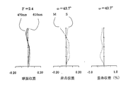
実施例1の投射用レンズを「縮小側で評価」した球面収差、非点収差、歪曲収差の図を図2に、コマ収差の図を図3に示す。各収差図は、546nmの波長を持つ緑色光の収差を示すが、球面収差図、コマ収差図には赤、青の光を代表して波長:610nmと470nmの収差も表示している。非点収差図におけるSはサジタル像面、Mはメリディオナル像面の収差を示す。他の実施例の収差図においても同様である。
【0078】
実施例2
図4に、実施例2の投射用レンズのレンズ構成を、図1に倣って示す。
【0079】
非球面
第1面
K=2.7584、A=0.6912×10− 5、B=−0.8998×10− 8、C=0.8289×10− 11、
D=−0.3867×10− 14、E=0.8927×10− 18
第2面
K=−0.8248、A=0.112×10− 4、B=−0.1853×10− 7、C=0.2269×10− 10、
D=−0.1129×10− 13、E=0.188×10− 17
第15面
K=72.28386、A=−0.11033×10− 4、B=0.622146×10− 7、
C=−0.762462×10− 9、D=0.436177×10− 11、E=−0.655053×10− 14 。
【0081】
各条件のパラメータの値
(1)Bf/f=2.674
(2)|f1/f|=2.013
(3)d/f=4.945
(4)ν2N−ν2P=28.0
(5)ν3P=55.5
(6)|f/f1p|=0.070
(7)|f/f2p|=0.029 。
【0082】
実施例2の投射用レンズを「縮小側で評価」した球面収差、非点収差、歪曲収差の図を図5に、コマ収差の図を図6に示す。
【0083】
実施例3
図7に、実施例3の投射用レンズのレンズ構成を、図1に倣って示す。
【0084】
非球面
第1面
K=2.8377、A=0.6393×10− 5、B=−0.9831×10− 8、C=0.8608×10− 11、
D=−0.3726×10− 14、E=0.7319×10− 18
第2面
K=−0.7618、A=0.1059×10− 4、B=−0.2085×10− 7、C=0.2326×10− 10、
D=−0.1039×10− 13、E=0.2549×10− 17
第15面
K=−1.5981、A=−0.1173×10− 4、B=0.6125×10− 7、C=−0.7762×10− 9、
D=0.4481×10− 11、E=−0.5828×10− 14 。
【0086】
各条件のパラメータの値
(1)Bf/f=3.193
(2)|f1/f|=1.808
(3)d/f=4.249
(4)ν2N−ν2P=32.5
(5)ν3P=62.2
(6)|f/f1p|=0.075
(7)|f/f2p|=0.029 。
【0087】
実施例3の投射用レンズを「縮小側で評価」した球面収差、非点収差、歪曲収差の図を図8に、コマ収差の図を図9に示す。
【0088】
実施例4
図10に、実施例4の投射用レンズのレンズ構成を、図1に倣って示す。
【0089】
第1レンズ群内の非球面レンズは拡大側から2番目に配置されている。
【0090】
非球面
第3面
K=2.5447、A=0.1212×10− 4、B=−0.1062×10− 7、C=0.1056×10− 10、
D=−0.3006×10− 14、E=0.1908×10− 18
第4面
K=−0.0375、A=0.1123×10− 4、B=−0.1488×10− 7、C=0.213×10− 10、
D=−0.1581×10− 13、E=−0.6769×10− 17
第15面
K=24.7162、A=−0.9793×10− 5、B=0.6892×10− 7、C=−0.7862×10− 9、
D=0.4061×10− 11、E=−0.4256×10− 14 。
【0092】
各条件のパラメータの値
(1)Bf/f=2.706
(2)|f1/f|=1.957
(3)d/f=4.823
(4)ν2N−ν2P=33.8
(5)ν3P=58.4
(6)|f/f1p|=0.095
(7)|f/f2p|=0.029
実施例4の投射用レンズを「縮小側で評価」した球面収差、非点収差、歪曲収差の図を図11に、コマ収差の図を図12に示す。
【0093】
実施例5
図13に、実施例5の投射用レンズのレンズ構成を、図1に倣って示す。
【0094】
非球面
第3面
K=6.9845、A=0.1975×10− 4、B=−0.1763×10− 7、C=0.1446×10− 10、
D=−0.1205×10− 14、E=0.1747×10− 17
第4面
K=0.0066、A=0.1734×10− 4、B=0.2585×10− 7、C=−0.5622×10− 10、
D=−0.3669×10− 13、E=0.3639×10− 15
第15面
K=28.8706、A=−0.1157×10− 4、B=0.768×10− 7、C=−0.8198×10− 9、
D=0.3965×10− 11、E=−0.5714×10− 14 。
【0096】
各条件のパラメータの値
(1)Bf/f=2.685
(2)|f1/f|=1.897
(3)d/f=4.173
(4)ν2N−ν2P=33.8
(5)ν3P=58.4
(8)|f/f1p|=0.181
(9)f/f2p=0.022
実施例5の投射用レンズを「縮小側で評価」した球面収差、非点収差、歪曲収差の図を図14に、コマ収差の図を図15に示す。
【0097】
上に挙げた実施例1〜5の投射用レンズは何れも、拡大側から縮小側に向かって、負の屈折力を持つ第1レンズ群I、正の屈折力を持つ第2レンズ群IIを配し、これら第1、第2レンズ群間に光路屈曲用の反射手段Mを配してなり、第1レンズ群Iは、3枚の「拡大側に凸のメニスカス負レンズ」で構成され、1枚が非球面レンズであり、第2レンズ群IIは、拡大側から正の屈折力を持つ第2レンズ前群IIfと正の屈折力を持つ第2レンズ後群IIrとを配し、第2レンズ後群IIrの拡大側焦点位置近傍に開口絞りSTを配置してなり、反射手段Mが配置される第1、第2レンズ群間はレンズ系中で最も大きな空気間隔をなし、第2レンズ前群IIfは、縮小側に大きな曲率を持つ負レンズと拡大側に大きな曲率を持つ正レンズの2枚が、小さな空気間隔を隔てて配列した構成であり、第2レンズ後群IIrは、縮小側に大きな曲率を持つ負レンズと両面が凸である正レンズの2枚の張り合わせによる接合レンズ、縮小側に凸のメニスカスの非球面レンズ、縮小側に大きな曲率の正レンズを、拡大側から上記順序に配して成り、全系の焦点距離:f 、第1レンズ群の焦点距離:f1、拡大側の共役点が無限遠の時の空気中におけるバックフォーカス:Bf、第1レンズ群と第2レンズ群との光軸上における間隔:dが、条件:
(1) 2.3 < Bf/f < 3.5
(2) 1.5 <|f1/f|<2.5
(3) 3.5 < d/f <7.0
を満足し、半画角40°以上を有する(請求項1)。
【0098】
実施例1〜5の投射用レンズは何れも、第2レンズ後群IIr内の接合レンズを構成する負レンズが、拡大側に緩い凸のメニスカス負レンズで(請求項2)、第2レンズ後群IIr内の非球面レンズが、拡大側の面のみ非球面である(請求項3)。
【0099】
実施例1〜5の投射用レンズはまた、第2レンズ前群IIfにおける、負レンズのアッべ数:ν2N、正レンズのアッべ数:ν2Pが、条件:
(4)15 < ν2N−ν2P < 50
を満足し(請求項4)、全系中において最も縮小側に配置された正レンズのアッべ数:ν3Pが、条件:
(5)50 < ν3P
を満足する(請求項5)。
【0100】
実施例1〜4の投射用レンズは、第1レンズ群I内における非球面を有するレンズがプラスチックレンズで、その焦点距離:f1p、全系の焦点距離:fが、条件:
(6)0 <|f/f1p|< 0.12
を満足し(請求項6)、第2レンズ後群IIr内における非球面を有するレンズがプラスチックレンズで、その焦点距離:f2p、全系の焦点距離:fが条件:
(7)0 <|f/f2p|< 0.03
を満足する(請求項7)。
【0101】
実施例5の投射用レンズは、第1レンズ群I内における非球面を有するレンズがプラスチックレンズで、その焦点距離:f1p、第2レンズ後群内における非球面を有するレンズが正の屈折力を持つプラスチックレンズで、その焦点距離:f2pが、全系の焦点距離:fに対して、条件:
(8)0 <|f/f1p|< 0.2
(9)0.008 <f/f2p< 0.03
を満足する(請求項8)。
【0102】
さらに、実施例1〜5の投射用レンズは何れも、第1レンズ群I内の非球面レンズと、この非球面レンズの縮小側に配置されたレンズとの間隔を可変とし、投射距離の変更に伴い発生する像面の湾曲を、上記間隔を変化させることにより補正することが可能である(請求項9)。
【0103】
従って、白色の光源の光を赤・緑・青の3色の光に分離し、それぞれ独立した3枚の液晶パネルを通過させ、これら画像情報を持つ光を色合成光学系のプリズムにより合成し、図16に示すように透過型スクリーンSCの背面から拡大投射表示する公知の投射型画像表示装置に、投射用レンズPLとして、上記実施例1〜5の適宜のものを搭載することにより、コンパクトでありながら高精細な画像を表示することが可能である(請求項10)。
【0104】
【発明の効果】
以上に説明したように、この発明によれば、半画角:40度以上の広画角でありながらも高い解像力を維持し、長いバックフォーカス、縮小側における高いテレセントリック性を有し、性能良好でコンパクト、低コストの投射用レンズおよびこれを搭載した投射型画像表示装置を実現できる。
【図面の簡単な説明】
【図1】実施例1のレンズ構成図である。
【図2】実施例1の球面収差、非点収差、歪曲収差を示す図である。
【図3】実施例1のコマ収差を示す図である。
【図4】実施例2のレンズ構成図である。
【図5】実施例2の球面収差、非点収差、歪曲収差を示す図である。
【図6】実施例2のコマ収差を示す図である。
【図7】実施例3のレンズ構成図である。
【図8】実施例3の球面収差、非点収差、歪曲収差を示す図である。
【図9】実施例3のコマ収差を示す図である。
【図10】実施例4のレンズ構成図である。
【図11】実施例4の球面収差、非点収差、歪曲収差を示す図である。
【図12】実施例4のコマ収差を示す図である。
【図13】実施例5のレンズ構成図である。
【図14】実施例5の球面収差、非点収差、歪曲収差を示す図である。
【図15】実施例5のコマ収差を示す図である。
【図16】この発明の投射用レンズを搭載した投射型画像表示装置を示す図である。
【図17】実施例1の投射距離を300mm延長したときの球面収差、非点収差、歪曲収差を示す図である。
【図18】実施例1の投射距離を300mm延長したときのコマ収差を示す図である。
【図19】実施例1の投射距離を300mm延長し、像面補正をしたときの球面収差、非点収差、歪曲収差を示す図である。
【図20】実施例1の投射距離を300mm延長し、像面補正をしたときのコマ収差を示す図である。
【符号の説明】
I 第1レンズ群
II 第2レンズ群
IIf 第2レンズ前群
IIr 第2レンズ後群
M 反射ミラー
ST 開口絞り
P 色合成光学系としてのプリズム
LB ライトバルブ
SC スクリーン
PL 投射用レンズ[0001]
BACKGROUND OF THE INVENTION
The present invention relates to a projection lens for enlarging and projecting an original image on a screen, and a projection type image display apparatus equipped with the projection lens.
[0002]
[Prior art]
A liquid crystal projector that enlarges and projects an image displayed on a liquid crystal panel or the like onto a display medium such as a screen has been widely used as a general TV broadcast, a video reproduction image, or a display device of a computer.
[0003]
Above all, each color image of red, green, and blue is displayed on three independent liquid crystal panels (liquid crystal light valves, etc.), and each color image is synthesized and displayed in an enlarged projection with a wide angle of view from the back of the transmissive screen. The “rear type three-panel liquid crystal projector” has a large screen, is thin, and has a high image definition because of its high definition.
[0004]
In a rear-type three-panel liquid crystal projector, in general, light from a white light source is separated into red, green, and blue colors by a color separation optical system, led to each liquid crystal panel, and emitted from each liquid crystal panel (on each liquid crystal panel) The image is two-dimensionally intensity-modulated by the displayed image) by a color synthesizing optical system and is incident on the projection lens. In this case, a “color combining optical system including a prism” is arranged.
[0005]
For this reason, a projection lens used in a rear type three-plate liquid crystal projector requires a “long back focus”.
[0006]
When the angle of the light beam incident on the color synthesis optical system from the liquid crystal panel changes, the spectral transmittance of the color synthesis optical system changes accordingly, and the brightness of each color in the projected color image changes according to the angle of view. The image is difficult to see. In order to avoid this, it is preferable that the projection lens has “a telecentric property that the angle of the principal ray is approximately parallel to the optical axis on the reduction side”.
[0007]
As a projection lens with a long back focus and telecentric on the reduction side, a so-called “retro focus type” in which a “negative refractive power lens group” and a “positive refractive power lens group” are arranged in order from the magnification side. However, this type of projection lens tends to have a large overall length, and how can it be applied to a projection-type image display device that requires a “compact thin outer shape in a direction perpendicular to the screen surface”? The question is whether to incorporate the display device without compromising its compactness.
[0008]
As a method for solving this problem, a “thin outline” is used for the projection type image display device by arranging a “reflecting means such as a mirror” between the lens groups of the retrofocus type projection lens having a large overall length and bending the optical path. The device to make it known is known (
[0009]
Further, in order to make the projection type image display apparatus thin by shortening the optical path of the imaging light flux as much as possible and to enlarge the display image, the projection lens needs to have a large angle of view. Of course, various aberrations should be corrected well so that the displayed image has high image quality, and high resolution should be obtained.
[0010]
[Patent Document 1]
Japanese Patent Laid-Open No. 9-218379
[Patent Document 2]
JP 2001-42211 A
[0011]
[Problems to be solved by the invention]
In order to meet the above requirements, the present invention has a half field angle: a wide field angle of 40 degrees or more, a high resolution, a long back focus and high telecentricity, and a compact optical path in which the optical path of the imaging light beam is bent between lens groups. An object of the present invention is to realize a projection lens and a projection type image display device having a thin outline using the projection lens.
[0012]
[Means for Solving the Problems]
As shown in FIG. 1, the projection lens according to
[0013]
The first lens group I includes three “negative meniscus lenses convex on the enlargement side”, and one is an aspheric lens. This aspherical lens may be any of the three meniscus negative lenses. In Examples 1, 2, and 3 to be described later, the “most magnification side lens” is an aspheric lens, and in Examples 4 and 5, the second lens from the magnification side is an aspheric lens.
[0014]
The second lens group II includes a second lens front group IIf having positive refractive power on the enlargement side and a second lens rear group IIr having positive refractive power on the reduction side, and enlargement of the second lens rear group IIr. An aperture stop ST is disposed in the vicinity of the side focal position.
[0015]
Between the first and second lens groups in which the reflecting means M is disposed, “the largest air gap in the lens system” is formed.
[0016]
The second lens front group IIf has a configuration in which a negative lens having a large curvature on the reduction side and a positive lens having a large curvature on the enlargement side are arranged with a small air gap.
[0017]
The second lens rear group IIr includes “a cemented lens formed by bonding together a negative lens having a large curvature on the reduction side and a positive lens having convex surfaces on both sides”, “a meniscus aspherical lens convex on the reduction side”, “ A positive lens having a large curvature on the reduction side is arranged in the above order from the enlargement side.
[0018]
In FIG. 1, the symbol P indicates “a prism that is a color synthesis optical system”, and the symbol LB indicates “a light valve such as a liquid crystal panel”.
[0019]
Focal length of the entire system:
(1) 2.3 <Bf / f <3.5
(2) 1.5 <| f1 / f | <2.5
(3) 3.5 <d / f <7.0
Satisfied.
[0020]
2. The projection lens according to
3. The projection lens according to
[0021]
The projection lens according to any one of
(4) 15 <ν2N−ν2P <50
Is preferably satisfied (claim 4).
[0022]
Further, in the projection lens according to any one of
(5) 50 <ν3P
Is preferably satisfied (Claim 5).
[0023]
6. The projection lens according to
(6) 0 <| f / f1p | <0.12
Is preferably satisfied (claim 6).
[0024]
The projection lens according to any one of
(7) 0 <| f / f2p | <0.03
Is preferably satisfied (claim 7).
[0025]
The projection lens according to any one of
(8) 0 <| f / f1p | <0.2
(9) 0.008 <f / f2p <0.03
It is also preferable to configure so as to satisfy (Claim 8).
[0026]
The projection lens according to any one of
The “projection distance” is a distance from the most enlarged lens surface of the projection lens to the screen.
[0027]
A projection type image display device according to the present invention includes the projection lens according to any one of
[0028]
The projection lens of the present invention has a “first lens group I having a negative refractive power” on the enlargement side, a reduction, in order to have a “long back focus” required for “arrangement of the color synthesizing optical system”. The “second lens group II having a positive refractive power” is arranged on the side, and the “retro focus type” in which the principal point is moved rearward (reduction side) of the lens.
[0029]
Condition (1) is a condition for ensuring a sufficient back focus necessary for a projection lens of a three-plate liquid crystal projector while maintaining a desired “large angle of view (half angle of view: 40 degrees or more)”. It is.
[0030]
If the lower limit of the condition (1) is exceeded while maintaining the “large field angle”, the back focus: Bf becomes short, and it is difficult to arrange a color combining optical system such as a prism between the projection lens and the liquid crystal panel. become. If the upper limit of the condition (1) is exceeded while maintaining a desired “sufficient back focus”, the focal length f of the entire system becomes small, and correction of various aberrations becomes difficult.
[0031]
Condition (2) is a condition for achieving both a sufficiently long back focus and good optical performance.
[0032]
In a retrofocus type lens, in general, the ratio of the back focus: Bf to the focal length:
Bf / f = 1-D / f1 (a)
It is represented by Therefore, as the value of | f1 | becomes smaller, the second term on the right side becomes larger with a positive value, and the value of back focus: Bf becomes larger.
[0033]
If the parameter: | f1 / f | exceeds the upper limit of the condition (2), | f1 | becomes too large, the negative refractive power of the first lens group becomes small, and it becomes difficult to obtain a desired back focus. .
[0034]
If the lower limit of condition (2) is exceeded, | f1 | becomes too small, and the negative refractive power of the first lens unit becomes excessive, and it is difficult to maintain good off-axis aberrations such as coma and field curvature. become.
[0035]
Condition (3) is a condition for appropriately ensuring a space necessary for arranging the reflecting means for bending the optical path and a long back focus.
[0036]
When the distance between the first lens group and the second lens group:
[0037]
However, when the distance d is too large and the parameter d / f exceeds the upper limit of the condition (3), the lens disposed on the enlargement side of the second lens group II becomes large, and the cost of the projection lens increases. Will be invited. On the contrary, if the parameter d / f exceeds the lower limit of the condition (3), it becomes difficult to ensure both “a long back focus and a space for arranging the reflecting means”.
[0038]
The projection lens of the present invention achieves high aperture efficiency while ensuring high telecentricity by disposing the aperture stop ST in the vicinity of the focal position on the enlargement side of the second lens rear group IIr.
[0039]
The retrofocus type projection lens is composed of a first lens group I having a negative refractive power and a second lens group II having a positive refractive power in order from the magnification side. When viewed from the center of the lens (aperture stop position), Since the refractive power is asymmetrically arranged, distortion is likely to occur greatly.
[0040]
In the projection lens according to the present invention, the first lens group I is composed of three “negative meniscus lenses convex toward the enlargement side”, thereby suppressing the occurrence of distortion to be small, and the three meniscus negative lenses have a space. Since it can be arranged close to each other, it is advantageous for downsizing.
[0041]
Since the first lens group I has an off-axis chief ray height (distance from the optical axis) larger than that of other lens groups, disposing an aspheric lens in the first lens group I causes distortion. Effective correction of aberrations becomes possible.
[0042]
The second lens front group IIf has a positive lens having a large curvature on the reduction side and a positive lens having a large curvature on the enlargement side, and has the above-described positive configuration. A design with a higher degree of freedom is possible compared to the case where a negative lens is cemented, and axial chromatic aberration, spherical aberration, etc. can be corrected satisfactorily by taking advantage of this advantage.
[0043]
In the projection lens according to claim 2, the negative lens constituting the cemented lens in the second lens rear group IIr is “a meniscus negative lens that is loosely convex on the enlargement side”, thereby appropriately correcting coma and the like. It is possible.
[0044]
Even in the projection lens, “aspheric surfaces on both surfaces of the aspheric lens used” increases design freedom and makes it easy to obtain high image quality, but severe accuracy against surface shape errors and eccentricity of the aspheric axis. It becomes difficult to reduce the cost. Therefore, the projection lens is required to “effectively arrange an aspheric surface with a small number of surfaces”.
[0045]
In the projection lens according to the third aspect, the aspherical surface of the aspherical lens disposed in the second lens rear group is disposed only on the enlargement side, and aberration correction is effectively performed.
[0046]
Condition (4) represents the “range of Abbe number difference” of the two lenses constituting the second lens front group IIf. When the lower limit value of the condition (4) is exceeded, it is difficult to effectively correct the longitudinal chromatic aberration by these two lenses.
[0047]
The off-axis principal ray incident on the projection lens from the liquid crystal panel is largely bent in the optical axis direction by the second lens rear group IIr having positive refractive power due to high telecentricity on the reduction side of the projection lens. At this time, if the difference in the wavelength of the “degree of ray bending” is large, the lateral chromatic aberration is greatly generated.
[0048]
In the projection lens according to
[0049]
In the projection lens according to the sixth aspect, the aspherical lens in the first lens group I can be reduced in cost as a plastic aspherical lens made of a plastic material that is inexpensive and easy to mold.
[0050]
Plastic lenses have a greater “change in focal length due to temperature” than optical glass. For this reason, if the refractive power of the plastic lens is large, the “change in focal length and focus position due to temperature” becomes large in the projection lens on which the plastic lens is mounted.
[0051]
The projection lens in the rear LCD projector is sealed in the housing after it is assembled, making it difficult to readjust the focus position and magnification (focal length). It is necessary to consider.
[0052]
Condition (6) is a condition that regulates the “degree of change in focal length due to temperature” of the plastic aspheric lens in the first lens group I in view of this point.
[0053]
If the parameter of condition (6): | f / f1p | exceeds the upper limit, the focal length of the plastic aspherical lens: f1p will change greatly when the temperature changes, and the “image magnification” will change greatly, and the focus will shift greatly. Is also undesirable.
[0054]
In the projection lens according to claim 7, the aspherical lens in the second lens rear group IIr is made of plastic, and the condition (7) indicates the “degree of change in focal length due to temperature” of the plastic aspherical lens. It is regulated.
The upper limit value of the condition (7) is smaller than the upper limit value of the condition (6). This is for the reason described below.
[0055]
The amount of movement of the focus position of the projection lens generated by the temperature change of the plastic lens: ΔL is the focal length of the plastic lens: fP, Light incident height: hP , Temperature dispersion number: ωPBy
ΔL = (hP 2/ FP) ・ ΩP (B)
It is represented by
[0056]
The light beam emitted from one point of the liquid crystal panel is incident on the second lens rear group IIr while spreading, but the light beam diameter becomes the maximum after reaching the maximum in the second lens rear group IIr. And enters the first lens group I.
[0057]
The incident light height of each plastic lens in the first lens group I and the second lens rear group IIr is h.P1, HP2Then, as described above, hP2Is hP1Larger than the square of these “ratio”: ε2(= (HP2/ HP1)2) Is in the range of about 4-10.
[0058]
The amount of movement of the focus position due to the temperature change: ΔL is the light incident height: h as in the above equation (b).P Therefore, the focal length of the plastic lens in the second lens rear group IIr must be four times larger than that of the plastic lens in the first lens group I. For this reason, the upper limit value 0.03 of the condition (7) is smaller than the upper limit value 0.12 of the condition (6).
[0059]
In the projection lens according to claim 8, a positive plastic lens is arranged in the second lens rear group IIr with respect to the negative plastic lens in the first lens group I, and the movement of the focus position due to temperature is negative. By offsetting with a positive plastic lens, we are trying to reduce it.
[0060]
The upper limit value of condition (8): 0.2 is larger than the upper limit value of condition (6): 0.12, which is canceled by the positive plastic lens arranged in the second lens rear group IIr. This is because the restriction on the negative plastic lens in the first lens group I is relaxed in anticipation of the effect of the above.
When the upper limit value of the condition (8) is exceeded, the refractive power of the negative plastic lens becomes large, and the refractive power of the positive plastic lens must also be increased, but the above-mentioned “ratio of incident light height: ε” The “error in canceling action” due to the variation also becomes large, and it becomes impossible to guarantee a change in the focus position due to the temperature.
[0061]
If the parameter of condition (9): f / f2p exceeds the lower limit value, the reverse action of the positive plastic lens in the second lens rear group IIr becomes smaller, and if the upper limit value is exceeded, the canceling action becomes excessive. Accordingly, “out of focus position change due to temperature” cannot be guaranteed outside the range of condition (9).
[0062]
Each of the projection lenses of the present invention includes a second lens rear group IIr, a cemented lens formed by bonding together a negative lens having a large curvature on the reduction side and a positive lens having convex surfaces on both sides, and a meniscus convex on the reduction side. By arranging the aspherical lens and a positive lens having a large curvature on the reduction side in the above order from the enlargement side, the lateral chromatic aberration, coma aberration, and astigmatism are satisfactorily corrected.
[0063]
In the rear projection type image display apparatus, in order to meet the demands of consumers, it is common to expand the product lineup by changing the size of the screen as a display screen in stages.
[0064]
However, if the projection distance (the distance from the projection lens to the screen) is changed in accordance with the screen size, the curvature of the image plane occurs around the screen, and the image quality deteriorates.
[0065]
In the projection lens of Example 1 to be described later, when the projection distance: 646 mm is extended to 946 mm and the size of the projection display is enlarged, the image is in light of the astigmatism diagram of FIG. 17 and the coma aberration diagram of FIG. As is apparent, a large curvature of the image plane occurs.
[0066]
Astigmatism diagram when the distance between the aspherical lens in the first lens group I (the lens on the most magnifying side) and the lens arranged on the reduction side of the aspherical lens is shortened by 0.5 mm. FIG. 19 shows a coma aberration diagram and FIG. As understood from these drawings, the adjustment of the lens interval corrects the curvature of the image plane and restores good image performance. Similar correction is possible when the projection distance is shortened and the size of the projected display is reduced. This correction function is the same in other embodiments.
[0067]
That is, as in the projection lens according to the ninth aspect, by changing the lens interval, it is possible to “simply correct the curvature of the image plane and project a good image on each size screen”.
[0068]
DETAILED DESCRIPTION OF THE INVENTION
Hereinafter, as specific embodiments, five examples will be given.
[0069]
In each embodiment, “S” indicates the surface number counted from the enlargement side, and “R” indicates the radius of curvature of each surface (including the surface of the aperture stop ST and the surface of the prism P that is the color synthesizing optical system). The paraxial radius of curvature), and “D” represents the surface spacing on the optical axis. “Nd” and “νd” indicate the refractive index and Abbe number of the material of each lens with respect to the d-line.
[0070]
“F” is the focal length of the projection lens, “F / No” is the F value representing brightness, “ω” is the half angle of view, and “obd” is the first surface of the lens (first lens group) from the object (screen) "Bf" represents the back focus in the air (without the prism). The unit of the quantity having the dimension of length is “mm”.
[0071]
The aspherical shape has an intersection with the optical axis as the origin, height relative to the optical axis: h, optical axis direction shift: Z, paraxial radius of curvature: R, conic constant: K, aspheric coefficient of higher order terms: As A, B, C, D, E, the formula:
Z = (1 / R) · h2/ [1 + √ {1− (1 + K) ・ (1 / R)2・ H2}]
+ A ・ hFour+ B ・ h6+ C ・ h8+ DhTen+ Eh12
The above-mentioned R, K, A, B, C, D, E are given and specified.
[0072]
Example 1
FIG. 1 shows the lens configuration of the projection lens of Example 1.
[0073]
A first lens group I, a reflecting mirror (planar mirror) M that bends the optical path, and a second lens group II are arranged from the enlargement side (upper side of the figure). The second lens group II is a second lens front group IIf, an aperture stop. ST is composed of the second lens rear group IIr. A prism P, which is a color synthesis optical system, is inserted between the projection lens and the light valve LB.
[0074]
The aspherical lens in the first lens group is disposed on the most enlarged side.
[0075]
Aspherical
First side
K = 2.45, A = 0.6777 × 10− Five, B = −0.10067 × 10− 7, C = 0.8269 × 10− 11,
D = −0.3722 × 10− 14, E = 0.8044 × 10− 18
Second side
K = -1.03, A = 0.1103 x 10− Four, B = −0.2251 × 10− 7, C = 0.252 × 10− Ten,
D = −0.1072 × 10− 13, E = 0.2334 × 10− 17
15th page
K = 20.3342, A = −0.1048 × 10− Four, B = 0.7108 × 10− 7, C = −0.8363 × 10− 9,
D = 0.4305 × 10− 11, E = −0.5109 × 10− 14 .
[0077]
Parameter value for each condition
(1) Bf / f = 2.671
(2) | f1 / f | = 2.063
(3) d / f = 5.279
(4) ν2N−ν2P= 30.9
(5) ν3P= 60.3
(6) | f / f1p | = 0.049
(7) | f / f2p | = 0.026
FIG. 2 shows a diagram of spherical aberration, astigmatism, and distortion aberration, and FIG. 3 shows a coma aberration diagram when the projection lens of Example 1 is “evaluated on the reduction side”. Each aberration diagram shows the aberration of green light having a wavelength of 546 nm, but the spherical aberration diagram and coma aberration diagram also show aberrations of wavelengths 610 nm and 470 nm, representing red and blue light. In the astigmatism diagram, S represents the sagittal image surface, and M represents the aberration of the meridional image surface. The same applies to the aberration diagrams of the other examples.
[0078]
Example 2
FIG. 4 shows the lens configuration of the projection lens of Example 2 according to FIG.
[0079]
Aspherical
First side
K = 2.7584, A = 0.6912 × 10− Five, B = −0.8998 × 10− 8, C = 0.8289 × 10− 11,
D = −0.3867 × 10− 14, E = 0.8927 × 10− 18
Second side
K = −0.8248, A = 0.112 × 10− Four, B = −0.1853 × 10− 7, C = 0.2269 × 10− Ten,
D = −0.1129 × 10− 13, E = 0.188 × 10− 17
15th page
K = 72.28386, A = −0.11033 × 10− Four, B = 0.622146 × 10− 7,
C = −0.762462 × 10− 9, D = 0.436177 × 10− 11, E = −0.655053 × 10− 14 .
[0081]
Parameter value for each condition
(1) Bf / f = 2.674
(2) | f1 / f | = 2.013
(3) d / f = 4.945
(4) ν2N−ν2P= 28.0
(5) ν3P= 55.5
(6) | f / f1p | = 0.070
(7) | f / f2p | = 0.029.
[0082]
FIG. 5 shows a diagram of spherical aberration, astigmatism, and distortion aberration, and FIG. 6 shows a diagram of coma aberration when the projection lens of Example 2 is “evaluated on the reduction side”.
[0083]
Example 3
FIG. 7 shows the lens configuration of the projection lens of Example 3 following FIG.
[0084]
Aspherical
First side
K = 2.8377, A = 0.6393 × 10− Five, B = −0.9831 × 10− 8, C = 0.8608 × 10− 11,
D = −0.3726 × 10− 14, E = 0.7319 × 10− 18
Second side
K = −0.7618, A = 0.1059 × 10− Four, B = −0.2085 × 10− 7, C = 0.2326 × 10− Ten,
D = −0.1039 × 10− 13, E = 0.549 × 10− 17
15th page
K = −1.5981, A = −0.1173 × 10− Four, B = 0.6125 × 10− 7, C = −0.7762 × 10− 9,
D = 0.4481 × 10− 11, E = −0.5828 × 10− 14 .
[0086]
Parameter value for each condition
(1) Bf / f = 3.193
(2) | f1 / f | = 1.808
(3) d / f = 4.249
(4) ν2N−ν2P= 32.5
(5) ν3P= 62.2
(6) | f / f1p | = 0.075
(7) | f / f2p | = 0.029.
[0087]
FIG. 8 shows a diagram of spherical aberration, astigmatism and distortion when the projection lens of Example 3 was “evaluated on the reduction side”, and FIG. 9 shows a diagram of coma aberration.
[0088]
Example 4
FIG. 10 shows the lens configuration of the projection lens of Example 4 according to FIG.
[0089]
The aspheric lens in the first lens group is arranged second from the magnification side.
[0090]
Aspherical
Third side
K = 2.5447, A = 0.1212 × 10− Four, B = −0.1062 × 10− 7, C = 0.1056 × 10− Ten,
D = −0.3006 × 10− 14, E = 0.1908 × 10− 18
4th page
K = −0.0375, A = 0.1123 × 10− Four, B = −0.1488 × 10− 7, C = 0.213 × 10− Ten,
D = −0.1581 × 10− 13, E = −0.6769 × 10− 17
15th page
K = 24.7162, A = −0.9793 × 10− Five, B = 0.6892 × 10− 7, C = −0.7862 × 10− 9,
D = 0.4061 × 10− 11, E = −0.4256 × 10− 14 .
[0092]
Parameter value for each condition
(1) Bf / f = 2.706
(2) | f1 / f | = 1.957
(3) d / f = 4.823
(4) ν2N−ν2P= 33.8
(5) ν3P= 58.4
(6) | f / f1p | = 0.095
(7) | f / f2p | = 0.029
FIG. 11 shows a diagram of spherical aberration, astigmatism and distortion when the projection lens of Example 4 is “evaluated on the reduction side”, and FIG. 12 shows a diagram of coma aberration.
[0093]
Example 5
FIG. 13 shows the lens configuration of the projection lens of Example 5 following FIG.
[0094]
Aspherical
Third side
K = 6.9845, A = 0.1975 × 10− Four, B = −0.1763 × 10− 7, C = 0.1446 × 10− Ten,
D = −0.1205 × 10− 14, E = 0.1747 × 10− 17
4th page
K = 0.0066, A = 0.1734 × 10− Four, B = 0.585 × 10− 7, C = −0.5622 × 10− Ten,
D = −0.3669 × 10− 13, E = 0.3639 × 10− 15
15th page
K = 28.8706, A = −0.1157 × 10− Four, B = 0.768 × 10− 7, C = −0.8198 × 10− 9,
D = 0.3965 × 10− 11, E = −0.5714 × 10− 14 .
[0096]
Parameter value for each condition
(1) Bf / f = 2.855
(2) | f1 / f | = 1.897
(3) d / f = 4.173
(4) ν2N−ν2P= 33.8
(5) ν3P= 58.4
(8) | f / f1p | = 0.181
(9) f / f2p = 0.022
FIG. 14 shows a diagram of spherical aberration, astigmatism, and distortion obtained by “evaluating on the reduction side” of the projection lens of Example 5, and FIG. 15 shows a diagram of coma aberration.
[0097]
Each of the projection lenses of Examples 1 to 5 described above includes the first lens group I having a negative refractive power and the second lens group II having a positive refractive power from the enlargement side toward the reduction side. The first lens group I is composed of three “negative meniscus lenses convex on the enlargement side”, and a reflecting means M for bending the optical path is arranged between the first and second lens groups. One lens is an aspheric lens, and the second lens group II includes a second lens front group IIf having a positive refractive power and a second lens rear group IIr having a positive refractive power from the magnifying side. An aperture stop ST is disposed in the vicinity of the enlargement-side focal position of the second lens rear group IIr, and the first and second lens groups in which the reflecting means M are disposed form the largest air gap in the lens system. The front lens group IIf is composed of a negative lens having a large curvature on the reduction side and a positive lens having a large curvature on the enlargement side. However, the second lens rear group IIr has a configuration in which a negative lens having a large curvature on the reduction side and a positive lens having convex surfaces on both sides are bonded to each other on the reduction side. A convex meniscus aspherical lens, a positive lens with a large curvature on the reduction side, arranged in the above order from the enlargement side, the focal length of the entire system: f, the focal length of the first lens group: f1, the enlargement side The back focus in the air when the conjugate point is infinity: Bf, the distance on the optical axis between the first lens group and the second lens group: d is the condition:
(1) 2.3 <Bf / f <3.5
(2) 1.5 <| f1 / f | <2.5
(3) 3.5 <d / f <7.0
And has a half angle of view of 40 ° or more.
[0098]
In any of the projection lenses of Examples 1 to 5, the negative lens constituting the cemented lens in the second lens rear group IIr is a meniscus negative lens that is loosely convex on the enlargement side (Claim 2), and the second lens rear. In the aspherical lens in the group IIr, only the enlargement side surface is aspherical.
[0099]
In the projection lenses of Examples 1 to 5, the Abbe number of the negative lens in the second lens front group IIf: ν2N, Positive lens Abbe number: ν2PBut the condition:
(4) 15 <ν2N−ν2P <50
(Claim 4) and the Abbe number of the positive lens arranged closest to the reduction side in the entire system: ν3PBut the condition:
(5) 50 <ν3P
(Claim 5).
[0100]
In the projection lenses of Examples 1 to 4, a lens having an aspheric surface in the first lens group I is a plastic lens, and its focal length is f1p, and the focal length of the entire system is f.
(6) 0 <| f / f1p | <0.12
(Claim 6), the lens having an aspheric surface in the second lens rear group IIr is a plastic lens, and its focal length is f2p, and the focal length of the entire system is f:
(7) 0 <| f / f2p | <0.03
(Claim 7).
[0101]
In the projection lens of Example 5, a lens having an aspheric surface in the first lens group I is a plastic lens, its focal length is f1p, and a lens having an aspheric surface in the second lens rear group has a positive refractive power. The focal length: f2p is a plastic lens, and the focal length: f of the entire system is:
(8) 0 <| f / f1p | <0.2
(9) 0.008 <f / f2p <0.03
Is satisfied (claim 8).
[0102]
Furthermore, in any of the projection lenses of Examples 1 to 5, the distance between the aspheric lens in the first lens group I and the lens disposed on the reduction side of the aspheric lens is variable, and the projection distance is changed. It is possible to correct the curvature of the image plane that occurs along with the above-mentioned change by changing the interval.
[0103]
Therefore, the light from the white light source is separated into three colors of red, green, and blue, passed through three independent liquid crystal panels, and the light having the image information is synthesized by the prism of the color synthesis optical system. As shown in FIG. 16, the projection lens PL is mounted with the appropriate one of the above-described
[0104]
【The invention's effect】
As described above, according to the present invention, the half field angle: a wide field angle of 40 degrees or more, while maintaining a high resolution, a long back focus, a high telecentricity on the reduction side, and a good performance. Thus, a compact and low-cost projection lens and a projection-type image display device equipped with the same can be realized.
[Brief description of the drawings]
FIG. 1 is a lens configuration diagram of Example 1. FIG.
2 is a diagram showing spherical aberration, astigmatism, and distortion of Example 1. FIG.
3 is a graph showing coma aberration in Example 1. FIG.
4 is a lens configuration diagram of Example 2. FIG.
5 is a diagram showing spherical aberration, astigmatism, and distortion in Example 2. FIG.
6 is a diagram showing coma aberration in Example 2. FIG.
7 is a lens configuration diagram of Example 3. FIG.
8 is a diagram showing spherical aberration, astigmatism, and distortion in Example 3. FIG.
9 is a graph showing coma aberration in Example 3. FIG.
10 is a lens configuration diagram of Example 4. FIG.
11 is a diagram showing spherical aberration, astigmatism, and distortion in Example 4. FIG.
12 is a graph showing coma aberration in Example 4. FIG.
13 is a lens configuration diagram of Example 5. FIG.
14 is a diagram showing spherical aberration, astigmatism, and distortion in Example 5. FIG.
15 is a graph showing coma aberration in Example 5. FIG.
FIG. 16 is a diagram showing a projection type image display device equipped with the projection lens of the present invention.
17 is a diagram showing spherical aberration, astigmatism, and distortion when the projection distance of Example 1 is extended by 300 mm. FIG.
FIG. 18 is a diagram showing coma aberration when the projection distance of Example 1 is extended by 300 mm.
FIG. 19 is a diagram illustrating spherical aberration, astigmatism, and distortion when the projection distance of Example 1 is extended by 300 mm and image plane correction is performed.
FIG. 20 is a diagram illustrating coma aberration when the projection distance in Example 1 is extended by 300 mm and image plane correction is performed.
[Explanation of symbols]
I First lens group
II Second lens group
IIf Second lens front group
IIr second lens rear group
M reflective mirror
ST Aperture stop
Prism as P color synthesis optical system
LB Light valve
SC screen
PL projection lens
Claims (10)
上記第1レンズ群は、3枚の拡大側に凸のメニスカス負レンズで構成され、そのうちの1枚が非球面レンズであり、
上記第2レンズ群は、拡大側から正の屈折力を持つ第2レンズ前群と、正の屈折力を持つ第2レンズ後群とを配し、上記第2レンズ後群の拡大側焦点位置近傍に開口絞りを配置してなり、
上記反射手段が配置される第1、第2レンズ群間は、レンズ系中で最も大きな空気間隔をなし、
上記第2レンズ前群は、縮小側に大きな曲率を持つ負レンズと拡大側に大きな曲率を持つ正レンズの2枚が、小さな空気間隔を隔てて配列した構成であり、
上記第2レンズ後群は、拡大側から順次、縮小側に大きな曲率を持つ負レンズと両面が凸である正レンズの2枚の張り合わせによる接合レンズ、縮小側に凸のメニスカスの非球面レンズ、縮小側に大きな曲率の正レンズを配して成り、
全系の焦点距離:f 、第1レンズ群の焦点距離:f1、拡大側の共役点が無限遠の時の空気中におけるバックフォーカス:Bf、第1レンズ群と第2レンズ群との光軸上における間隔:dが、条件:
(1) 2.3 < Bf/f < 3.5
(2) 1.5 <|f1/f|< 2.5
(3) 3.5 < d/f <7.0
を満足することを特徴とする半画角40°以上を有する投射用レンズ。A first lens group having a negative refractive power and a second lens group having a positive refractive power are arranged from the enlargement side to the reduction side, and a reflecting means for bending the optical path between the first and second lens groups. And
The first lens group is composed of three meniscus negative lenses convex on the enlargement side, one of which is an aspheric lens,
The second lens group includes a second lens front group having a positive refractive power from the magnification side and a second lens rear group having a positive refractive power, and a magnification-side focal position of the second lens rear group. An aperture stop is placed in the vicinity,
Between the first and second lens groups in which the reflecting means is disposed, the largest air space in the lens system is formed,
The second lens front group has a configuration in which a negative lens having a large curvature on the reduction side and a positive lens having a large curvature on the enlargement side are arranged with a small air gap between them,
The second lens rear group includes, in order from the enlargement side, a cemented lens formed by bonding a negative lens having a large curvature on the reduction side and a positive lens having convex surfaces on both sides, a meniscus aspherical lens convex on the reduction side, Consists of a positive lens with a large curvature on the reduction side,
Focal length of the entire system: f 1, focal length of the first lens group: f 1, back focus in the air when the magnification side conjugate point is infinity: Bf, optical axes of the first lens group and the second lens group The distance above: d is the condition:
(1) 2.3 <Bf / f <3.5
(2) 1.5 <| f1 / f | <2.5
(3) 3.5 <d / f <7.0
A projection lens having a half angle of view of 40 ° or more.
第2レンズ後群内の接合レンズを構成する負レンズが、拡大側に緩い凸のメニスカス負レンズであることを特徴とする投射用レンズ。The projection lens according to claim 1,
A projection lens, wherein the negative lens constituting the cemented lens in the rear group of the second lens is a meniscus negative lens that is loosely convex on the enlargement side.
第2レンズ後群内の非球面レンズが、拡大側の面のみ非球面であることを特徴とする投射用レンズ。The projection lens according to claim 1 or 2,
A projection lens, wherein the aspherical lens in the rear group of the second lens is aspherical only on the enlargement side.
第2レンズ前群における、負レンズのアッべ数:ν2N、正レンズのアッべ数:ν2Pが、条件:
(4)15 < ν2N−ν2P < 50
を満足することを特徴とする投射用レンズ。The projection lens according to any one of claims 1 to 3,
In the second lens front group, the negative lens Abbe number: ν 2N and the positive lens Abbe number: ν 2P are:
(4) 15 <ν 2N −ν 2P <50
Projection lens characterized by satisfying
全系中において最も縮小側に配置された正レンズのアッべ数:ν3Pが条件:
(5)50 < ν3P
を満足することを特徴とする投射用レンズ。The projection lens according to any one of claims 1 to 4,
Abbe number of positive lens arranged on the most reduction side in the entire system: ν 3P is a condition:
(5) 50 <ν 3P
Projection lens characterized by satisfying
第1レンズ群内における非球面を有するレンズがプラスチックレンズで、その焦点距離:f1p、全系の焦点距離:fが、条件:
(6)0 <|f/f1p|< 0.12
を満足することを特徴とする投射用レンズ。In the projection lens according to any one of claims 1 to 5,
The lens having an aspheric surface in the first lens group is a plastic lens, and its focal length is f1p, and the focal length of the entire system is f.
(6) 0 <| f / f1p | <0.12
Projection lens characterized by satisfying
第2レンズ後群内における非球面を有するレンズがプラスチックレンズで、その焦点距離:f2p、全系の焦点距離:fが、条件:
(7)0 <|f/f2p|< 0.03
を満足することを特徴とする投射用レンズ。In the projection lens according to any one of claims 1 to 5,
A lens having an aspheric surface in the second lens rear group is a plastic lens, and its focal length is f2p, and the focal length of the entire system is f.
(7) 0 <| f / f2p | <0.03
Projection lens characterized by satisfying
(8)0 <|f/f1p|< 0.2
(9)0.008 <f/f2p< 0.03
を満足することを特徴とする投射用レンズ。6. The projection lens according to claim 1, wherein the lens having an aspheric surface in the first lens group is a plastic lens, and has a focal length of f1p and an aspheric surface in the second lens rear group. The lens is a plastic lens having a positive refractive power, and its focal length: f2p is relative to the focal length: f of the entire system.
(8) 0 <| f / f1p | <0.2
(9) 0.008 <f / f2p <0.03
Projection lens characterized by satisfying
Priority Applications (1)
| Application Number | Priority Date | Filing Date | Title |
|---|---|---|---|
| JP2003127187A JP4340468B2 (en) | 2003-05-02 | 2003-05-02 | Projection lens and projection-type image display device |
Applications Claiming Priority (1)
| Application Number | Priority Date | Filing Date | Title |
|---|---|---|---|
| JP2003127187A JP4340468B2 (en) | 2003-05-02 | 2003-05-02 | Projection lens and projection-type image display device |
Publications (2)
| Publication Number | Publication Date |
|---|---|
| JP2004333688A JP2004333688A (en) | 2004-11-25 |
| JP4340468B2 true JP4340468B2 (en) | 2009-10-07 |
Family
ID=33503826
Family Applications (1)
| Application Number | Title | Priority Date | Filing Date |
|---|---|---|---|
| JP2003127187A Expired - Fee Related JP4340468B2 (en) | 2003-05-02 | 2003-05-02 | Projection lens and projection-type image display device |
Country Status (1)
| Country | Link |
|---|---|
| JP (1) | JP4340468B2 (en) |
Families Citing this family (7)
| Publication number | Priority date | Publication date | Assignee | Title |
|---|---|---|---|---|
| WO2013080953A1 (en) | 2011-12-01 | 2013-06-06 | 三菱電機株式会社 | Projection optical system and projection image display apparatus |
| US9746652B2 (en) | 2015-06-10 | 2017-08-29 | Ricoh Company, Ltd. | Projection lens and image display device |
| JP6524548B2 (en) * | 2017-04-11 | 2019-06-05 | エスゼット ディージェイアイ テクノロジー カンパニー リミテッドSz Dji Technology Co.,Ltd | Lens system, imaging device, moving body and system |
| CN109960099B (en) * | 2019-04-30 | 2024-03-15 | 成都极米科技股份有限公司 | Non-coaxial projection light source system |
| JP2021006858A (en) | 2019-06-28 | 2021-01-21 | セイコーエプソン株式会社 | Projection optical system and projector |
| JP2021006859A (en) * | 2019-06-28 | 2021-01-21 | セイコーエプソン株式会社 | Projection optics and projector |
| CN116299985B (en) * | 2023-05-17 | 2023-08-29 | 歌尔光学科技有限公司 | Projection lens and projection module |
-
2003
- 2003-05-02 JP JP2003127187A patent/JP4340468B2/en not_active Expired - Fee Related
Also Published As
| Publication number | Publication date |
|---|---|
| JP2004333688A (en) | 2004-11-25 |
Similar Documents
| Publication | Publication Date | Title |
|---|---|---|
| JP4864600B2 (en) | Projection type zoom lens and projection type display device | |
| US8320048B2 (en) | Projection lens and projection-type display apparatus using the lens | |
| JP5042708B2 (en) | Projection lens and projection display device using the same | |
| EP3457191B1 (en) | Projection optical system and projector | |
| US7965449B2 (en) | Projection lens system and projection type display apparatus using the same | |
| US7663806B2 (en) | Projection lens and projection type display device using the same | |
| US20050036206A1 (en) | Zoom lens and image projection apparatus having the same | |
| US20050122598A1 (en) | Projection lens | |
| US20080137216A1 (en) | Projection lens | |
| JP5026929B2 (en) | Projection lens and projection-type image display device | |
| JP4340469B2 (en) | Projection lens and projection-type image display device | |
| JP4750318B2 (en) | Projection zoom lens | |
| JP4750319B2 (en) | Projection zoom lens | |
| JP4590044B2 (en) | Projection device | |
| US11061308B2 (en) | Projection optical system and projector | |
| JP2004233609A (en) | Projection lens system and projector | |
| JP4739810B2 (en) | Projection lens and projector device | |
| JP4340468B2 (en) | Projection lens and projection-type image display device | |
| JP2008309991A (en) | Projection lens and projection display apparatus using the same | |
| JP4418650B2 (en) | Zoom lens and image projection apparatus having the same | |
| JP4757990B2 (en) | Projection lens | |
| JP4340432B2 (en) | Projection zoom lens | |
| JP4532630B2 (en) | Projection lens | |
| JP4177633B2 (en) | Wide-angle lens and video enlargement projection system, video projector, rear projector, and multivision system using the same | |
| JP4469141B2 (en) | Projection zoom lens and projection-type image display device |
Legal Events
| Date | Code | Title | Description |
|---|---|---|---|
| A621 | Written request for application examination |
Free format text: JAPANESE INTERMEDIATE CODE: A621 Effective date: 20060425 |
|
| TRDD | Decision of grant or rejection written | ||
| A01 | Written decision to grant a patent or to grant a registration (utility model) |
Free format text: JAPANESE INTERMEDIATE CODE: A01 Effective date: 20090623 |
|
| A01 | Written decision to grant a patent or to grant a registration (utility model) |
Free format text: JAPANESE INTERMEDIATE CODE: A01 |
|
| A61 | First payment of annual fees (during grant procedure) |
Free format text: JAPANESE INTERMEDIATE CODE: A61 Effective date: 20090706 |
|
| R150 | Certificate of patent or registration of utility model |
Free format text: JAPANESE INTERMEDIATE CODE: R150 |
|
| FPAY | Renewal fee payment (event date is renewal date of database) |
Free format text: PAYMENT UNTIL: 20120710 Year of fee payment: 3 |
|
| FPAY | Renewal fee payment (event date is renewal date of database) |
Free format text: PAYMENT UNTIL: 20150710 Year of fee payment: 6 |
|
| R250 | Receipt of annual fees |
Free format text: JAPANESE INTERMEDIATE CODE: R250 |
|
| LAPS | Cancellation because of no payment of annual fees |