JP4340125B2 - Slot machine, winning determination method and program for slot machine - Google Patents
Slot machine, winning determination method and program for slot machine Download PDFInfo
- Publication number
- JP4340125B2 JP4340125B2 JP2003367628A JP2003367628A JP4340125B2 JP 4340125 B2 JP4340125 B2 JP 4340125B2 JP 2003367628 A JP2003367628 A JP 2003367628A JP 2003367628 A JP2003367628 A JP 2003367628A JP 4340125 B2 JP4340125 B2 JP 4340125B2
- Authority
- JP
- Japan
- Prior art keywords
- signal
- reel
- fluctuation
- start switch
- random number
- Prior art date
- Legal status (The legal status is an assumption and is not a legal conclusion. Google has not performed a legal analysis and makes no representation as to the accuracy of the status listed.)
- Expired - Fee Related
Links
Images


Landscapes
- Slot Machines And Peripheral Devices (AREA)
Description
この発明は、遊技機及び遊技機の入賞判定方法並びにプログラムに関する。 The present invention relates to a gaming machine, a winning determination method for a gaming machine, and a program.
スロットマシン等の遊技機にはメダルの投入口が設けられており、遊技者は所定の枚数のメダルを投入してゲームを楽しむことができる。遊技に必要なメダルは、遊技ホール内に設けられたメダル貸機等で借りることができ、所望の遊技機のメダル投入口に投入することによりゲームを開始することができる。 A gaming machine such as a slot machine is provided with a medal slot so that a player can enjoy a game by inserting a predetermined number of medals. The medals necessary for the game can be borrowed with a medal lending machine provided in the game hall, and the game can be started by inserting it into the medal slot of a desired gaming machine.
従来の遊技機の動作は次のようなものであった。
先ず、スタートスイッチが操作されることにより、スタートスイッチがONとなる。これを受けて遊技機内部の入賞抽選手段により抽選処理が行われる。ここで所定の役に当選すると入賞フラグがセットされる。回転リールの回転が開始する。ストップスイッチが操作されることにより、ストップスイッチがONとなる。そして、対応する回転リールの回転が停止する。全部の回転リールに対応するストップスイッチの操作が行われた後、入賞フラグ成立中に当該入賞フラグに対応する入賞図柄が有効入賞ライン上に揃ったか否か、すなわち、入賞が確定したか否かが判定される。入賞が確定したと判定された場合、入賞図柄に相当するメダルが払い出される。
The operation of the conventional gaming machine was as follows.
First, when the start switch is operated, the start switch is turned on. In response to this, a lottery process is performed by a winning lottery means inside the gaming machine. Here, when a predetermined combination is won, a winning flag is set. The rotating reel starts to rotate. When the stop switch is operated, the stop switch is turned on. Then, the rotation of the corresponding rotating reel is stopped. After the stop switches corresponding to all the rotating reels are operated, whether or not the winning symbols corresponding to the winning flag are aligned on the effective winning line while the winning flag is established, that is, whether or not the winning is confirmed. Is determined. When it is determined that the winning is confirmed, a medal corresponding to the winning symbol is paid out.
抽選処理の評価が例えば外れの場合は所定の図柄が揃わないように設定され(いわゆる蹴飛ばし)、当たりの場合はストップスイッチが所定のタイミングで押下されることなどを条件に所定の図柄が揃うように設定される(いわゆる引き込み)。つまり、抽選処理において当選しているときのみ所定の条件の下で図柄が揃い入賞することにより、メダルが払い出されるが、当選しないときはストップスイッチをどのように操作してもメダルが払い出されることはない。これはメダルの払い出しを一定確率に保つためである。これを実現するため抽選処理において乱数発生器が用いられている。 For example, when the evaluation of the lottery process is out of place, it is set so that the predetermined symbols are not aligned (so-called kicking), and when winning, the predetermined symbols are aligned on the condition that the stop switch is pressed at a predetermined timing. (So-called pull-in). In other words, only when winning in the lottery process, medals are paid out by winning a winning pattern under a predetermined condition, but when not winning, medals are paid out regardless of how the stop switch is operated. There is no. This is to keep the medal payout at a certain probability. In order to realize this, a random number generator is used in the lottery process.
遊技機の乱数発生器は例えばカウンタを用いて乱数を擬似的に発生させるものであった。この場合に発生する乱数はある程度の規則性をもち、そのため予測可能な面があった。遊技者がスタートスイッチを巧みに操作することにより抽選確率を予め定められた値以上にする可能性を否定できなかった。 A random number generator of a gaming machine generates a random number using a counter, for example. The random numbers generated in this case have a certain degree of regularity, and therefore have a predictable aspect. The possibility that the player could make the lottery probability over a predetermined value by skillfully operating the start switch could not be denied.
そこで、本発明は、スタートスイッチの操作によっても特定の乱数を取得できることがなく、抽選確率の点で特定の遊技者が有利にならない遊技機及び遊技機の入賞判定方法並びにプログラムを提供することを目的とする。 Therefore, the present invention provides a gaming machine, a winning determination method for a gaming machine, and a program in which a specific random number cannot be obtained even by operating a start switch, and a specific player is not advantageous in terms of a lottery probability. Objective.
この発明は、遊技者が操作するスタートスイッチの信号に基づき抽選を行い、当該抽選結果に基づき入賞判定を行う入賞抽選手段と、複数の回転リールと、前記複数の回転リールを回転させるリール駆動部と、前記複数の回転リールの回転位置を検出するリール位置検出回路と、前記複数の回転リールの回転を停止させるための複数のストップスイッチと、前記リール駆動部及び前記リール位置検出回路と接続され、前記スタートスイッチ及び前記複数のストップスイッチからの信号に基づき前記複数の回転リールの回転及び停止を制御する制御装置とを備えるスロットマシンにおいて、
前記入賞抽選手段は、抽選を行うための前記スタートスイッチの信号を受け、前記スタートスイッチの信号に揺らぎを加えて出力する揺らぎ発生器を含み、
前記揺らぎ発生器は、タイミングカウンタと、前記スタートスイッチの信号に基づき前記タイミングカウンタの出力を読み込み、読み込んだ値を元にカウントを行う揺らぎ発生用カウンタと、前記タイミングカウンタに対して所定の契機でカウントの停止及び再開を指示する更新停止信号発生器とを備え、
前記揺らぎ発生用カウンタの桁上がり信号が揺らぎの加えられた信号として出力され、
前記入賞抽選手段は、揺らぎの加えられた前記信号に基づき抽選を行い、
前記更新停止信号発生器は、前記複数のストップスイッチのいずれかが押下されたときとき前記タイミングカウンタに対してカウントの停止を指示し、
前記回転リールが停止したとき前記タイミングカウンタに対してカウントの再開を指示するものである。
The present invention relates to a winning lottery means for performing lottery based on a signal of a start switch operated by a player and performing a winning determination based on the lottery result, a plurality of rotating reels, and a reel driving unit for rotating the plurality of rotating reels. A reel position detection circuit for detecting a rotation position of the plurality of rotating reels, a plurality of stop switches for stopping the rotation of the plurality of rotating reels, and the reel driving unit and the reel position detection circuit. A slot machine comprising: a control device that controls rotation and stop of the plurality of rotating reels based on signals from the start switch and the plurality of stop switches;
The winning lottery means includes a fluctuation generator that receives a signal of the start switch for performing the lottery and outputs a fluctuation to the signal of the start switch,
The fluctuation generator reads a timing counter, an output of the timing counter based on a signal of the start switch, and performs a count based on the read value, and a fluctuation generation counter that performs a predetermined trigger on the timing counter. An update stop signal generator for instructing stop and restart of the count,
The carry signal of the fluctuation generating counter is output as a signal with fluctuation added,
The winning lottery means performs a lottery based on the signal subjected to fluctuation,
The update stop signal generator instructs the timing counter to stop counting when any of the plurality of stop switches is pressed,
When the rotating reel stops, the timing counter is instructed to resume counting.
この発明は、遊技者が操作するスタートスイッチの信号に基づき抽選を行い、当該抽選結果に基づき入賞判定を行う入賞抽選手段と、複数の回転リールと、前記複数の回転リールを回転させるリール駆動部と、前記複数の回転リールの回転位置を検出するリール位置検出回路と、前記複数の回転リールの回転を停止させるための複数のストップスイッチと、前記リール駆動部及び前記リール位置検出回路と接続され、前記スタートスイッチ及び前記複数のストップスイッチからの信号に基づき前記複数の回転リールの回転及び停止を制御する制御装置とを備えるスロットマシンにおいて入賞判定を行う方法であって、
前記スタートスイッチの信号を受けて、前記スタートスイッチの信号に揺らぎを加える第1ステップと、
乱数を発生する第2ステップと、
前記第2ステップで発生された乱数の中から前記第1ステップで揺らぎの加えられた信号に基づき乱数を抽出する第3ステップと、
予め用意された入賞判定テーブルを参照して前記第3ステップで抽出された乱数の入賞の有無及び又は入賞の種類を判定する第4ステップとを備え、
前記第1ステップでは、
前記スタートスイッチの信号に基づきタイミングカウンタの出力を読み込み、読み込んだ値を元に揺らぎ発生用カウンタでカウントを行い、前記揺らぎ発生用カウンタの桁上がり信号が前記揺らぎの加えられた信号として出力され、
前記複数のストップスイッチのいずれかが押下されたとき前記タイミングカウンタでのカウントを停止し、
前記回転リールが停止したとき前記タイミングカウンタでのカウントを再開する、ものである。
The present invention relates to a winning lottery means for performing lottery based on a signal of a start switch operated by a player and performing a winning determination based on the lottery result, a plurality of rotating reels, and a reel driving unit for rotating the plurality of rotating reels. A reel position detection circuit for detecting a rotation position of the plurality of rotating reels, a plurality of stop switches for stopping the rotation of the plurality of rotating reels, and the reel driving unit and the reel position detection circuit. A method for determining a prize in a slot machine comprising a control device for controlling rotation and stop of the plurality of rotating reels based on signals from the start switch and the plurality of stop switches,
A first step of receiving a signal from the start switch and adding a fluctuation to the signal from the start switch;
A second step of generating a random number;
A third step of extracting a random number from the random number generated in the second step based on the signal added with the fluctuation in the first step;
A fourth step of determining the presence / absence of the random number extracted in the third step and / or the type of the winning with reference to a winning determination table prepared in advance,
In the first step,
Based on the signal of the start switch, the output of the timing counter is read, the counter for fluctuation generation is counted based on the read value, and the carry signal of the counter for fluctuation generation is output as the signal with the fluctuation added,
When any of the plurality of stop switches is pressed, the counting by the timing counter is stopped,
When the rotating reel stops, the counting by the timing counter is resumed.
この発明は、遊技者が操作するスタートスイッチの信号に基づき抽選を行い、当該抽選結果に基づき入賞判定を行う入賞抽選手段と、複数の回転リールと、前記複数の回転リールを回転させるリール駆動部と、前記複数の回転リールの回転位置を検出するリール位置検出回路と、前記複数の回転リールの回転を停止させるための複数のストップスイッチと、前記リール駆動部及び前記リール位置検出回路と接続され、前記スタートスイッチ及び前記複数のストップスイッチからの信号に基づき前記複数の回転リールの回転及び停止を制御する制御装置とを備えるスロットマシンにおいて入賞判定を行う方法をコンピュータに実行させるためのプログラムであって、
前記スタートスイッチの信号を受けて、前記スタートスイッチの信号に揺らぎを加える第1ステップと、
乱数を発生する第2ステップと、
前記第2ステップで発生された乱数の中から前記第1ステップで揺らぎの加えられた信号に基づき乱数を抽出する第3ステップと、
予め用意された入賞判定テーブルを参照して前記第3ステップで抽出された乱数の入賞の有無及び又は入賞の種類を判定する第4ステップとを備え、
前記第1ステップでは、
前記スタートスイッチの信号に基づきタイミングカウンタの出力を読み込み、読み込んだ値を元に揺らぎ発生用カウンタでカウントを行い、前記揺らぎ発生用カウンタの桁上がり信号が前記揺らぎの加えられた信号として出力され、
前記複数のストップスイッチのいずれかが押下されたとき前記タイミングカウンタでのカウントを停止し、
前記回転リールが停止したとき前記タイミングカウンタでのカウントを再開する、ものである。
The present invention relates to a winning lottery means for performing lottery based on a signal of a start switch operated by a player and performing a winning determination based on the lottery result, a plurality of rotating reels, and a reel driving unit for rotating the plurality of rotating reels. A reel position detection circuit for detecting a rotation position of the plurality of rotating reels, a plurality of stop switches for stopping the rotation of the plurality of rotating reels, and the reel driving unit and the reel position detection circuit. A program for causing a computer to execute a method for determining a prize in a slot machine comprising a control device for controlling rotation and stop of the plurality of rotating reels based on signals from the start switch and the plurality of stop switches. And
A first step of receiving a signal from the start switch and adding a fluctuation to the signal from the start switch;
A second step of generating a random number;
A third step of extracting a random number from the random number generated in the second step based on the signal added with the fluctuation in the first step;
A fourth step of determining the presence / absence of the random number extracted in the third step and / or the type of the winning with reference to a winning determination table prepared in advance,
In the first step,
Based on the signal of the start switch, the output of the timing counter is read, the counter for fluctuation generation is counted based on the read value, and the carry signal of the counter for fluctuation generation is output as the signal with the fluctuation added,
When any of the plurality of stop switches is pressed, the counting by the timing counter is stopped,
When the rotating reel stops, the counting by the timing counter is resumed.
この発明に係るプログラムは、例えば、記録媒体に記録される。
媒体には、例えば、EPROMデバイス、フラッシュメモリデバイス、フレキシブルディスク、ハードディスク、磁気テープ、光磁気ディスク、CD(CD−ROM、Video−CDを含む)、DVD(DVD−Video、DVD−ROM、DVD−RAMを含む)、ROMカートリッジ、バッテリバックアップ付きのRAMメモリカートリッジ、フラッシュメモリカートリッジ、不揮発性RAMカートリッジ等を含む。
The program according to the present invention is recorded on a recording medium, for example.
Examples of the medium include EPROM device, flash memory device, flexible disk, hard disk, magnetic tape, magneto-optical disk, CD (including CD-ROM and Video-CD), DVD (DVD-Video, DVD-ROM, DVD- RAM), ROM cartridge, RAM memory cartridge with battery backup, flash memory cartridge, nonvolatile RAM cartridge, and the like.
また、電話回線等の有線通信媒体、マイクロ波回線等の無線通信媒体等の通信媒体を含む。インターネットもここでいう通信媒体に含まれる。 In addition, a communication medium such as a wired communication medium such as a telephone line and a wireless communication medium such as a microwave line is included. The Internet is also included in the communication medium here.
媒体とは、何等かの物理的手段により情報(主にデジタルデータ、プログラム)が記録されているものであって、コンピュータ、専用プロセッサ等の処理装置に所定の機能を行わせることができるものである。 A medium is a medium in which information (mainly digital data, a program) is recorded by some physical means, and allows a processing device such as a computer or a dedicated processor to perform a predetermined function. is there.
この発明によれば、抽選に用いる信号に揺らぎを持たせることにより抽選の際の乱数発生に対する人為的な影響を軽減できる。したがって、意図的に入賞を狙うことや不正行為を防止できる。 According to the present invention, artificial influence on random number generation at the time of lottery can be reduced by giving fluctuation to a signal used for lottery. Therefore, it is possible to intentionally aim for winning and to prevent fraud.
発明の実施の形態1.
この発明の実施の形態に係る遊技機について図面を参照して説明する。
図1は、発明の実施の形態に係る遊技機(スロットマシン)の正面図である。
スロットマシン10で遊技を楽しもうとする遊技者は、まずメダル貸機(図示しない)等から遊技媒体であるメダルを借り、メダル投入装置のメダル投入口100に直接メダルを入れる。メダル投入口100は、スロットマシン10の正面で略中央の位置に設けられている。
A gaming machine according to an embodiment of the present invention will be described with reference to the drawings.
FIG. 1 is a front view of a gaming machine (slot machine) according to an embodiment of the invention.
A player who wants to enjoy a game with the
スロットマシン10は、四角箱状の筐体11を有する。前記筐体11の中央部及び上部には、遊技者側に向かって臨む四角窓状の表示窓12が形成されている。そして、この中央部の表示窓12の中央には、三個の回転リール40の図柄61を見ることができる図柄表示窓13が形成されている。ベットスイッチ16は、回転リール40の下方に位置するスイッチであって、貯留メダル数を減じてメダル投入に代える。精算スイッチ17は、回転リールの斜め下方に位置するスイッチであって、貯留した投入メダルを払い出す。スタートスイッチ30は回転リール40の斜め下方に位置するレバーであって、遊技メダルの投入若しくはベットスイッチ16の投入を条件に、リールユニット60の駆動を開始させる。ストップスイッチ50は、リールユニット60の駆動を停止させるためのものである。リールユニット60は、三個の回転リール40とから構成されている。そして、各回転リール40は、合成樹脂からなる回転ドラムと、この回転ドラムの周囲に貼付されるテープ状のリールテープ42とを備えている。このリールテープ42の外周面には、複数個(例えば21個)の図柄61が表示されている。62は各種の演出を行うための液晶表示部である。
The
スロットマシン10の内部には、図示していないが、スロットマシン10の全体の動作を制御するための制御装置が内蔵されている。制御装置は、図示しないが、CPUを中心に構成され、ROM、RAM、I/O等を備えている。そして、CPUがROMに記憶されたプログラムを読み込むことで動作し、スタートスイッチ30及びストップスイッチ50の操作に基づき回転リール40の回転及び停止を制御するとともに、ランプやスピーカ等の表示を制御する。
Inside the
スタートスイッチ30は、前述のように回転リール40の斜め下方に位置するレバーであって、遊技メダルの投入若しくはベットスイッチ16の投入を条件に、または、「再遊技(Replay)」時には前遊技からの所定時間経過を条件に、リールユニット60の駆動を開始させるためのものである。
As described above, the
ストップスイッチ50は、前述のようにリールユニット60の駆動を停止させるためのものである。具体的には、ストップスイッチ50は、各回転リール40に対応した三個のスイッチから構成され、各回転リール40の下方に1個ずつ配置されているものである。回転リール40に対応したストップスイッチ50の操作により、当該対応した回転リール40の回転を停止するように設定されている。
The
メダルの投入若しくはベットスイッチ16の投入を条件に、または、「再遊技(Replay)」時には前遊技から所定時間経過を条件に、スタートスイッチ30を操作すると、リールユニット60が駆動され、三個の回転リール40が回転を開始する。その後、ストップスイッチ50の一個を操作すると、当該対応する回転リール40の回転が停止する。そして、ストップスイッチ50を三個全て操作すると、三個の回転リール40の回転が全て停止する。このとき、表示窓12の有効入賞ライン上に、予め設定された図柄61が停止すると、ホッバーユニット65を介して所定枚数のメダルが払い出される。なお、メダルを払い出す代わりに、クレジットしてもよい。
When the
前述の制御装置は、スタートスイッチ30及びストップスイッチ50の操作に基づき回転リール40の回転及び停止を制御する際に、予め定めた抽選確率に基づいて入賞資格を得たか否かの入賞判定の抽選を行う入賞抽選手段を含む。この入賞抽選手段による抽選結果が当選である場合に入賞フラグが成立し、この入賞フラグ成立中に、回転リール40の停止図柄の組み合わせが予め定められた入賞図柄と一致したことを条件に入賞が確定し、遊技者にメダルの払い出しや、特別遊技等の利益が付与されるように設定されている。
When the control device controls the rotation and stop of the
図2は入賞抽選手段のブロック図である。入賞抽選手段は制御装置に含まれ、当該装置は、具体的にはメイン基板のROMに記憶されたプログラムを同上のCPUが実行することにより及び/又はハードウエアにより実現される。入賞抽選手段は、図2に示すように、揺らぎ発生器1、乱数発生器2、乱数抽出器3、判定部4、及び、入賞判定テーブル5を含む。なお、入賞抽選手段の構成は図2に示したものに限定されない。
FIG. 2 is a block diagram of the winning lottery means. The winning lottery means is included in the control device, and specifically, the device is realized by the above CPU executing a program stored in the ROM of the main board and / or by hardware. As shown in FIG. 2, the winning lottery means includes a
揺らぎ発生器1はスタートスイッチ30からの信号を受け、これに揺らぎを加えて出力するものである。この詳細は後述する。
The
乱数発生器2は、入賞抽選用の乱数を所定の領域内で発生させるものである。例えば、0〜一定数の範囲において任意の数値を所定の確率で発生させる。
The
乱数抽出器3は、乱数発生器2が発生する乱数を所定の条件(例えば、スタートスイッチ30の操作)で抽出するものである。乱数発生器2は所定間隔で連続的に乱数を発生させているが、そのうちの一部が乱数抽出器3により抽出される。なお、この抽出した乱数を抽出乱数データとする。
The
入賞判定テーブル5は、乱数発生器2がとる乱数の全領域に対応して、各入賞態様ごとに区分された領域を有するものである。例えば、0〜一定数の範囲を複数に区分し、ひとつの区分(領域)を外れとし、他の区分(領域)を入賞1、入賞2、・・・というように設定する。
The winning determination table 5 has an area divided for each winning mode corresponding to the entire area of random numbers taken by the
判定部4は、乱数抽出器3が抽出した抽出乱数データを、入賞判定テーブル5の抽選確率データと参照する。すなわち、当該抽出乱数データを、乱数発生器2がとる乱数の全領域中の各入賞態様ごとに区分された入賞判定領域データそれぞれと照合し、当該抽出乱数データが属する入賞態様に対応する当選を決定するものである。例えば、抽出された乱数の数値が、入賞判定テーブル5のどの区分(領域)に属するか調べ、その区分が例えば入賞1の区分であれば「入賞1」と判定される。同様に、抽出された乱数の数値が入賞判定テーブル5の外れの区分(領域)に属すれば「外れ」と判定される。
The
抽選処理の評価が例えば外れの場合は所定の図柄が揃わないように設定され(いわゆる蹴飛ばし)、当たりの場合はストップスイッチが所定のタイミングで押下されることなどを条件に所定の図柄が揃うように設定される(いわゆる引き込み)。そして、所定の図柄が揃えば入賞図柄に相当するメダルが払い出される。 For example, when the evaluation of the lottery process is out of place, it is set so that the predetermined symbols are not aligned (so-called kicking), and when winning, the predetermined symbols are aligned on the condition that the stop switch is pressed at a predetermined timing. (So-called pull-in). And if predetermined symbols are prepared, medals corresponding to winning symbols are paid out.
入賞抽選はスタートスイッチ30の押下信号に基づいて行われるが、本発明の実施の形態では当該押下信号をそのまま使用するのではなく、揺らぎ発生器1により当該押下信号に揺らぎを与えた後の信号を使用することを特徴とする。このことを図3を参照して説明する。
The winning lottery is performed based on the pressing signal of the
図3(a)はスタートスイッチ30の押下信号と揺らぎ発生器1が出力する乱数抽出命令の関係を示すタイミングチャートである。揺らぎ発生器1はスタートスイッチ30の押下信号から遅延Tだけ遅れた信号を出力する。この乱数抽出命令により乱数が抽出される。抽出するタイミングが異なれば乱数抽出器3で抽出される乱数も異なってくる。遅延Tは一定値ではなく、スタートレバー30の押下ごとに毎回異なる値をとるので、抽出される乱数値を予測することはより困難となる。このように揺らぎ発生器1を設けることにより、たとえ乱数発生器2による乱数が一様でなく、仮に一定の規則性をもち予測可能な面があったとしても、抽選に用いられる乱数を予測することはできなくなる。遊技者が一定のタイミングでスタートスイッチ30を操作したところで抽選確率を所定値以上にすることはできないのである。
FIG. 3A is a timing chart showing the relationship between the pressing signal of the
これに対し、図3(b)に示すように従来はスタートレバー押下信号をそのまま用いて乱数を抽出していたので、乱数発生器2による乱数が一様でなく、仮に一定の規則性を持つ場合には抽選に用いられる乱数を予測する可能性を否定できなかった。
On the other hand, as shown in FIG. 3B, since the random number is conventionally extracted using the start lever pressing signal as it is, the random number generated by the
これに対し、図2の入賞抽選手段によれば、抽選処理において遊技者自身が抽選を行う意味でスタートレバー押下信号を用いるが、揺らぎ発生器1により乱数取得の際に当該信号にさらに揺らぎを持たせることにより、遊技機外部からはタイミングが取れない。したがって、不正行為などは困難になる。
On the other hand, according to the winning lottery means of FIG. 2, the start lever pressing signal is used in the meaning that the player himself performs a lottery in the lottery process, but when the random number is acquired by the
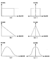
次に、揺らぎ発生器1において発生する遅延Tの性質について説明する。遅延Tは不規則に毎回異なる値をとる、すなわち揺らぐ。ここでいう揺らぎとは、スタートスイッチ30の押下信号の受信から乱数抽出器3に対する乱数抽出命令の発生までの時間が毎回不規則に(予測困難に)変わるという意味である。遅延Tは完全にランダムで一様の分布をすることが望ましいが、実用上はそれぞれの遅延Tが一定の割合で発生するものでも差し支えない。規則的でなければよい。遅延Tの分布の例を図4(a)〜(c)に示す。これらの図は遅延時間とその発生頻度を模式的に表したものである。
Next, the nature of the delay T generated in the
図4(a)(a’)の例では、遅延時間は一定の範囲で一様の分布をなし、所定範囲内であればどの遅延時間も同程度発生する。なお、点線で示すように範囲を限定しなくてもよい。同図(a)は遅延時間が0以上の場合を示し、同図(b)は遅延時間がある値を中心にその前後に分布する場合を示す(以下同様)。 In the example of FIGS. 4A and 4A ', the delay time has a uniform distribution in a certain range, and any delay time occurs within the predetermined range. Note that the range need not be limited as indicated by the dotted line. FIG. 4A shows a case where the delay time is 0 or more, and FIG. 4B shows a case where the delay time is distributed around a certain value (hereinafter the same).
図4(b)(b’)の例では、遅延時間は一定の範囲で発生するが、遅延時間が長くなるほどその発生頻度は直線的に少なくなる。 In the examples of FIGS. 4B and 4B, the delay time occurs within a certain range, but the frequency of occurrence decreases linearly as the delay time increases.
図4(c)(c’)の例では、所定の遅延時間で分布のピークをもち、これを中心に発生頻度は徐々に少なくなる。同図(c’)はいわゆる正規分布に類似する分布を示す。 In the example of FIGS. 4C and 4C, there is a distribution peak at a predetermined delay time, and the frequency of occurrence gradually decreases around this. FIG. 5C 'shows a distribution similar to a so-called normal distribution.
遅延Tを発生させる具体的な手法として、公知のアルゴリズム(モンテカルロ法など)を用いたり、熱雑音を用いた物理的な乱数を利用することができる。遅延Tは完全にランダムで一様の分布をすることが望ましいが、実用上はそれぞれの遅延Tが所定の割合で発生するものでも差し支えない。ハードウエアで揺らぎ発生器1を実現した例を図5に示す。
As a specific method for generating the delay T, a known algorithm (Monte Carlo method or the like) can be used, or a physical random number using thermal noise can be used. Although it is desirable that the delays T be completely random and have a uniform distribution, in practice, the delays T may be generated at a predetermined rate. An example in which the
図5において、1aは所定のクロックで動作して0から所定値までの数値を繰り返し出力するタイミングカウンタ、1bは所定のクロックで動作する揺らぎ発生用カウンタである。2は乱数発生器としてのカウンタ、3は乱数抽出器としてのラッチレジスタである。揺らぎ発生用カウンタ1bのキャリー(桁上がり)はラッチレジスタ3のラッチクロックとなる。揺らぎ発生用カウンタ1bは、スタートスイッチ30の押下信号でタイミングカウンタ1aの出力を読み込み、このプリセット値を元にカウントしていくので、キャリーの出力されるタイミングはプリセット値に依存する。タイミングカウンタ1a、揺らぎ発生用カウンタ1b、乱数用のカウンタ2はそれぞれ異なる周波数・異なる位相のクロックで動作し、これらの間で相互に干渉することなく、互いに同期も持たないものとする。したがって、揺らぎ発生用カウンタ1bにプリセットされる値は外部から予測困難であり、毎回異なるので、キャリーのタイミングが様々に揺らぐことになる。
In FIG. 5, 1a is a timing counter that operates with a predetermined clock and repeatedly outputs a numerical value from 0 to a predetermined value, and 1b is a fluctuation generating counter that operates with a predetermined clock. 2 is a counter as a random number generator, and 3 is a latch register as a random number extractor. The carry (carry) of the
図6は、図5の装置の動作説明図(タイミングチャート)である。スタートレバー信号が有効となったとき(t1)、タイミングカウンタ1aの値(揺らぎ値)が揺らぎ発生用カウンタ1bに取り込まれる(A部)。揺らぎ発生用カウンタ1bが0に戻った際(B部)に出力されるキャリーでカウンタ2の値をラッチレジスタ3に取り込む。
FIG. 6 is an operation explanatory diagram (timing chart) of the apparatus of FIG. When the start lever signal becomes valid (t1), the value (fluctuation value) of the
次に、上記構成を備えたスロットマシンの動作の概略について図7及び図8に示したフローを用いて説明する。 Next, an outline of the operation of the slot machine having the above configuration will be described with reference to the flowcharts shown in FIGS.
先ず、図7に示すステップS1において、スタートスイッチ30が操作されることにより、スタートスイッチ30がONとなる。そして、次のステップS2に進む。
ステップS2において、図2の入賞抽選手段により抽選処理が行われる。そして、次のステップS3に進む。
First, in step S1 shown in FIG. 7, when the
In step S2, lottery processing is performed by the winning lottery means shown in FIG. Then, the process proceeds to the next step S3.
ステップS3において、回転リール40の回転が開始する。そして、次のステップS4に進む。
ステップS4において、ストップスイッチ50が操作されることにより、ストップスイッチ50がONとなる。そして、次のステップS5に進む。
ステップS5において、回転リール40の回転停止処理が行われる。そして、次のステップS6に進む。
In step S3, the rotation of the
In step S4, when the
In step S5, rotation stop processing for the
ステップS6において、三個の回転リール40に対応するストップスイッチ50の操作が行われたか否かが判定される。そして、三個の回転リール40に対応するストップスイッチ50の操作が行われたと判定された場合、次のステップS7に進む。
ステップS7において、入賞フラグ成立中に当該入賞フラグに対応する入賞図柄が有効入賞ライン上に揃ったか否か、すなわち、入賞が確定したか否かが判定される。そして、入賞が確定したと判定された場合、次のステップS8に進む。
In step S6, it is determined whether or not the operation of the
In step S7, it is determined whether or not the winning symbols corresponding to the winning flag are aligned on the effective winning line while the winning flag is established, that is, whether or not the winning is confirmed. If it is determined that the winning is confirmed, the process proceeds to the next step S8.
ステップS8において、入賞図柄に相当するメダルが払い出される。そして、次のステップS9に進む。
ステップS9において、BBゲームやRBゲームの特別遊技に入賞確定した際、当該特別遊技の入賞確定回数が一つ増えた状態で、カウントされる。
In step S8, medals corresponding to winning symbols are paid out. Then, the process proceeds to next Step S9.
In step S9, when a winning decision is made for a special game of the BB game or RB game, the number of winning decisions for the special game is incremented by one.
上述したステップS2の抽選処理について図8のフローを用いて説明する。
ステップS10において、入賞抽選手段の揺らぎ発生器1によりスタートスイッチ押下信号に揺らぎを加える。そして、次のステップS11に進む。
ステップS11において、乱数発生器2により発生された乱数の中から揺らぎの加えられた信号に基づき乱数抽出器3により乱数が抽出される。そして、次のステップS12に進む。
The lottery process in step S2 described above will be described using the flow of FIG.
In step S10, a fluctuation is added to the start switch pressing signal by the
In step S <b> 11, random numbers are extracted by the
ステップS12において、抽出された乱数が乱数抽出器3の内部に記憶される。そして、次のステップS13に進む。
ステップS13において、判定器4により、抽出された乱数と、入賞判定テーブル5の入賞判定領域データとの比較が行われる。そして、次のステップS14に進む。
In step S12, the extracted random number is stored inside the
In step S <b> 13, the
ステップS14において、判定器4により、抽出された乱数が、入賞判定テーブル5のどの入賞態様に含まれるか決定され、抽選処理の評価が決定される。そして、次のステップS15に進む。
ステップS15において、抽選処理の評価が例えば外れの場合は所定の図柄が揃わないように設定され(いわゆる蹴飛ばし)、当たりの場合はストップスイッチが所定のタイミングで押下されることなどを条件に所定の図柄が揃うように設定される(いわゆる引き込み)。そして、抽選処理が終了する。
In step S <b> 14, the
In step S15, if the evaluation of the lottery process is out of place, for example, the predetermined symbols are set so as not to be aligned (so-called kicking), and if the win is determined, the stop switch is pressed at a predetermined timing. It is set so that the symbols are aligned (so-called pull-in). Then, the lottery process ends.
発明の実施の形態1によれば、遊技者自身が抽選を行う意味でスタートレバー押下信号を用いるが、乱数取得の際に当該信号にさらに揺らぎを持たせることにより、遊技機外部からはタイミングが取れない。したがって、意図的に入賞を狙うことや不正行為は困難になる。
According to
発明の実施の形態2.
揺らぎをさらに不規則にし予測できないようにするために、タイミングカウンタ1aの出力ビットのビット入替を行うビット入替部を備え、揺らぎ発生用カウンタ1bがビット入替部の出力を読み込むように構成してもよい。
In order to make the fluctuation even more irregular and unpredictable, it is possible to provide a bit replacement unit that performs bit replacement of the output bits of the
図9にその構成例を示す。同図において、ビット入替部6は配線あるいはプリント基板のパターンの入れ替えによってビット入替を行っている。このためビット入替のパターンは固定的である。同図の例ではタイミングカウンタ1a出力のLSB(QH)が揺らぎ発生用カウンタ1b入力のMSB(D1)に接続され、タイミングカウンタ1a出力の他のビットはそれぞれ1/2だけ重みの小さな揺らぎ発生用カウンタ1b入力のビットに接続されている。つまり、QGがD8に、QFがD7に、以下同様に、QAがD2に接続される。このようなビット入替は右に1ビットシフトしたことと等価である。
FIG. 9 shows an example of the configuration. In the figure, a
上記のように接続された場合において、タイミングカウンタ1aの出力がどのように変換されるか図10及び図11を参照して説明する。タイミングカウンタ1aとしてカウンタを用いた場合、タイミングカウンタ1aは0,1,2,3,4,・・・を順次出力する。しかし、ビット入替部6で上記のようにビットが入れ替えられていると、揺らぎ発生用カウンタ1bが受け取るデータは0,8,1,9,2,・・・となる。このように単純なビットの入れ替えでも数値は大きく変化する。不正行為を行う者は乱数が0,1,2,3,4,・・・のように規則正しく発生され、大当たりの間隔が一定であることを知り、これを前提として不正行為を試みている。そこで、上記のようなビット入替を行うだけでも抽選結果の予測は困難になり、不正行為防止に効果がある。
How the output of the
図9のビット入替の例はビット全体を1ビットシフトするものであった。ビット入替の手法として、他にビットの入れ替えがある。以下、ビットの入れ替えについて説明する。 In the example of bit replacement in FIG. 9, the entire bit is shifted by 1 bit. Another bit replacement technique is bit replacement. Hereinafter, the replacement of bits will be described.
ビットの入れ替えは1組以上のビットを交換することである。乱数を構成する複数のビットの一部を入れ替えることについてシミュレーション結果に基づき具体的に説明する。以下の例は8ビットの場合である。なお、以下の説明における「変化の周期」とはビットの入れ替えを行ったときにCPUが受けるデータの変化の周期であり、「変化の振幅」とは同じくデータの変化の幅である(変化の幅が一定でないときはその最大値)。具体的には図12を参照されたい。 Bit exchange is to exchange one or more sets of bits. The replacement of some of the plurality of bits constituting the random number will be specifically described based on the simulation result. The following example is for 8 bits. In the following description, the “change period” is the data change period received by the CPU when bits are exchanged, and the “change amplitude” is the data change width (change change). If the width is not constant, its maximum value). Specifically, refer to FIG.
(1)1組のビットを入れ替える
シミュレーション結果を図13に示す。ビットの組み合わせを適宜選択することにより変化の振幅を2乃至128、変化の周期を2乃至32とすることができる。図示しないが1組のビットを入れ替えたときのグラフは、振幅が大きいときでも右上がりの線形であるので、あまり効果がないと考えられる。後述するように、変化の周期は短く、かつ、変化の振幅は大きいほうが好ましい。この観点から1組のビット入れ替えを評価すると、このビット入れ替えにはあまり好ましくないビット入れ替えが含まれている。
(1) Replacing one set of bits The simulation result is shown in FIG. By appropriately selecting the combination of bits, the change amplitude can be set to 2 to 128, and the change period can be set to 2 to 32. Although not shown, the graph when one set of bits is exchanged is considered to be not very effective because it is linear to the right even when the amplitude is large. As will be described later, it is preferable that the change period is short and the change amplitude is large. If one set of bit swapping is evaluated from this point of view, this bit swapping includes less desirable bit swapping.
(2)2組以上のビットを入れ替える
シミュレーション結果を図14に示す。この場合は変化の振幅を32又は128、変化の周期を2とすることができる。2組以上のビットを入れ替えたときのグラフは振幅が大きく、しかもビット入替前の右上がりの線形形状とはかなり異なるので効果を期待できる。変化の周期は短く、かつ、変化の振幅は大きいほうが好ましいという観点から2組のビット入れ替えを評価すると、図14に示された全てのビット入れ替えは好ましいものである。したがって少なくとも2組以上のビット入れ替えを行うことが好ましい。
(2) Replacing two or more sets of bits The simulation result is shown in FIG. In this case, the change amplitude can be 32 or 128, and the change period can be 2. The graph when two or more sets of bits are exchanged has a large amplitude, and since the graph is quite different from the linear shape rising to the right before the bit exchange, an effect can be expected. From the viewpoint that it is preferable that the change period is short and the change amplitude is large, all of the bit exchanges shown in FIG. 14 are preferable. Therefore, it is preferable to exchange at least two sets of bits.
好ましくは、変化の振幅が大きく、しかも変化の周期が小さいとよい。そのためには最上位ビットと最下位ビットの入れ替えることが好ましい。このようにすれば1組のビットの入れ替えでもある程度効果を奏すると考えられる。 Preferably, the amplitude of change is large and the period of change is small. For this purpose, it is preferable to exchange the most significant bit and the least significant bit. In this way, it is considered that even if one set of bits is exchanged, an effect is obtained to some extent.
この発明の実施の形態2のようにビットの入れ替えを行えば、揺らぎをさらに不規則かつ予測困難にすることができる。 If bits are exchanged as in the second embodiment of the present invention, fluctuations can be made more irregular and difficult to predict.
図9の説明においてビット入替部6を配線や印刷基板のパターンで実現すると説明したが、ビット入替部6を例えば図15〜図17のように実現してもよい。これらの例によればビット入替部6の入替パターンは外部からの信号で変更できるので、当該入替パターンを適宜変更するようにしてもよい。
In the description of FIG. 9, it has been described that the
ビット入替パターン変更指令信号として上記以外にもストップスイッチからの信号、リールの回転開始又は停止信号、タイマからの時刻、日付又は曜日信号、ビッグボーナス(BB)などの入賞報知信号などを使用することができる。 In addition to the above, as a bit replacement pattern change command signal, a signal from a stop switch, a reel rotation start or stop signal, a time from a timer, a date or day signal, a big bonus (BB) winning notification signal, or the like is used. Can do.
ビット入替パターンを遊技ごとに変えるときは、その契機として抽選のタイミングが好ましい。あるいは、同じような乱数(一定範囲内の数値)が続けて発生した場合、それが予め定められた回数以上になったらビット入替パターンを変化させるようにしてもよい。例えばBBに連続2回又は5回中3回入賞したらビット入替パターンを変化させる。 When changing the bit replacement pattern for each game, the lottery timing is preferable. Alternatively, when similar random numbers (numerical values within a certain range) are continuously generated, the bit replacement pattern may be changed when the number exceeds a predetermined number of times. For example, if the BB is won twice continuously or three times out of five times, the bit replacement pattern is changed.
図15はビット入替部6にシフトレジスタを使用した例を示す。同図(a)は接続の概略を示し、同図(b)は処理手順を示す。入力されたQA〜QHのデータが右又は左方向へ指定されただけシフトされ、D1〜D8として出力される。右シフトのとき最も右側のビットのデータは右シフト出力からでて左側の右シフト入力に入力される。左シフトのとき最も左側のビットのデータは左シフト出力からでて右側の左シフト入力に入力される。
FIG. 15 shows an example in which a shift register is used for the
ビット入替パターンを決めるのは、シフト方向の入力と、クロック(CLK)入力である。図15においてビット入替パターンを変える場合、図15のクロックにパルスを1つ以上入力すればよい。このときのシフト方向は任意である。ただし、図15の例ではパルスを8つ入力すると元に戻る。スタートスイッチが押し下げられるごとにクロックパルスを入力するようにしてもよい。このとき、例えばBBに連続2回又は5回中3回入賞したらシフトの方向を逆にするようにしてもよい。 It is the input in the shift direction and the clock (CLK) input that determines the bit replacement pattern. When changing the bit replacement pattern in FIG. 15, one or more pulses may be input to the clock in FIG. The shift direction at this time is arbitrary. However, in the example of FIG. 15, it returns to the original state when eight pulses are input. A clock pulse may be input every time the start switch is depressed. At this time, for example, if the BB is won twice consecutively or three times out of five times, the shift direction may be reversed.
図16はビット入替部6にROM(Read Only Memory)を使用した例を示す。同図(a)は接続の概略を示す。A0〜A9はアドレス入力端子を示す。同図(b)はROMのビット入替パターンのマッピングの例を示す。乱数が8ビットの場合、図のように0〜255にビットシフトなし(アドレスとして入力されたデータをそのまま出力する)、256〜511に第1ビットシフトパターン、512〜767に第2ビットシフトパターン、768〜1023に第3ビットシフトパターンを記憶させておく。各ビットシフトパターンの内容は任意であり、右又は左に1〜7ビットシフトしたパターンや、1組又は2組のビットを入れ替えたパターンを記憶させることができる。
FIG. 16 shows an example in which a ROM (Read Only Memory) is used for the
ビット入替パターンを決めるのは、図16ではアドレスA8,A9の信号である。図16においてビット入替パターンを変える場合、アドレスA8,A9の信号を変えればよい。例えば、スタートスイッチ押下信号で動作するカウンタを設けておき、このカウンタの出力をアドレスA8,A9に入力するようにしてもよい。 The bit replacement pattern is determined by signals at addresses A8 and A9 in FIG. In FIG. 16, when changing the bit replacement pattern, the signals of the addresses A8 and A9 may be changed. For example, a counter that operates in response to a start switch pressing signal may be provided, and the output of this counter may be input to addresses A8 and A9.
図17はビット入替部6にマルチプレクサを使用した例を示す。例えば、8ビットから1ビットを選択するマルチプレクサを8個用いる。それぞれのマルチプレクサは3ビットの制御信号でいずれかの信号を選択するから、所望のビット入替パターンになるようなマルチプレクサの制御信号を生成する。例えば、制御信号として000を入力したらD8にQHが接続され、001を入力したらD8にQGが接続される(以下同様)。
FIG. 17 shows an example in which a multiplexer is used for the
この発明の実施の形態2によればビット入替部6を例えばシフトレジスタ、ROM、マルチプレクサで構成することにより、ビット入替パターンを適宜変更できる。例えば、スタートスイッチ押下信号、ストップスイッチからの信号、リールの回転開始又は停止信号、タイマからの時刻、日付又は曜日信号、ビッグボーナス(BB)などの入賞報知信号などを使用することができる。ビット入替パターンを適宜変更することにより、抽選に用いられる乱数はさらに不規則なものになり、不正行為は非常に困難になるので、不正行為を効果的に防止できる。
According to the second embodiment of the present invention, the bit replacement pattern can be appropriately changed by configuring the
なお、以上の説明においてハードウエアを用いてビット入れ替えを行っているが、ソフトウエアでビット入れ替えを行ってもよい。 In the above description, bit replacement is performed using hardware, but bit replacement may be performed using software.
発明の実施の形態3.
揺らぎをさらに不規則にし予測できないようにするために、タイミングカウンタ1a(あるいは揺らぎ発生用カウンタ1b)のカウンタ動作を所定の契機で停止又は再開するようにするようにしてもよい。これによりタイミングカウンタ1a(あるいは揺らぎ発生用カウンタ1b)の値が時間経過と同期しないようになる。
In order to make the fluctuation more irregular and unpredictable, the counter operation of the
乱数の更新を停止又は再開することの契機として例えば次のようなものがある。
(1)任意のストップスイッチ(停止ボタン)50からの信号に基づき乱数更新を停止させ、リール駆動部(後述)やリール位置検出回路(後述)からのリールの停止信号に基づき更新を再開させる。これは、停止するまでの回転リール(回胴)40の滑りを利用するものである。この滑りの程度はストップボタン押下のタイミングや抽選結果などによって毎回不規則に変化する。
(2)図示しないメダルセレクタからのメダルの投入の検出信号に基づき乱数更新を停止させ、スタートスイッチ30からの信号に基づき更新を再開させる。
(3)スタートスイッチ30からの信号に基づき乱数更新を停止させ、リール位置検出回路からのリールのインデックス検出信号基づき更新を再開させる。リールの停止状態により最初(あるいは特定回数目まで)のインデックス検出までの時間は毎回不規則に変化する。具体的には、あるひとつのリールを予め定めておき、当該リールについて回転を開始した後に最初に(あるいは特定回数目の)インデックスを検出した時間を利用する。あるいは、3つ又は4つあるリールのインデックス検出信号のうち複数を選択して合成し(例えば論理和を求める)、その最初の(あるいは特定回数目の)インデックス検出信号を利用するようにしてもよい。
(4)任意のストップスイッチ(例えば第1ストップスイッチ)50からの信号に基づき乱数更新を停止させ、他の任意のストップスイッチ(第2ストップスイッチ)50からの信号に基づき更新を再開させる。
(5)サブコマンド送信要求に基づき乱数更新を停止させ、サブコマンド送信開始に応じて更新を再開させる。サブコマンド送信要求を受けてから実際にサブコマンドを送信するまでの時間は、CPUの処理状況により毎回異なる。例えば、0乃至36msの間で変化する。
For example, there are the following triggers for stopping or restarting the update of the random number.
(1) The random number update is stopped based on a signal from an arbitrary stop switch (stop button) 50, and the update is restarted based on a reel stop signal from a reel drive unit (described later) or a reel position detection circuit (described later). This utilizes the sliding of the rotating reel (rotating drum) 40 until it stops. The degree of this slip changes irregularly every time the stop button is pressed or the lottery result.
(2) The random number update is stopped based on a medal insertion detection signal from a medal selector (not shown), and the update is restarted based on a signal from the
(3) The random number update is stopped based on the signal from the
(4) The random number update is stopped based on a signal from an arbitrary stop switch (for example, the first stop switch) 50, and the update is restarted based on a signal from another arbitrary stop switch (second stop switch) 50.
(5) The random number update is stopped based on the subcommand transmission request, and the update is restarted when the subcommand transmission is started. The time from when the subcommand transmission request is received until the subcommand is actually transmitted varies depending on the processing status of the CPU. For example, it varies between 0 and 36 ms.
上記(1)及び(5)の例について詳細に説明する。(2)(4)は上記以上の説明を要しないし、(3)は(1)の説明を参照すれば十分理解できる。 The examples (1) and (5) will be described in detail. (2) (4) does not require the above description, and (3) can be fully understood by referring to the description of (1).
(1)
任意のひとつのストップスイッチ(停止ボタン)50からの信号に基づき乱数更新を停止させ、リール駆動部やリール位置検出回路からのリールの停止信号に基づき更新を再開させる、というものである。これは、停止するまでの回転リール(回胴)40の滑りを利用するものである。滑りの程度は毎回不規則に変化する。
(1)
The random number update is stopped based on a signal from an arbitrary one stop switch (stop button) 50, and the update is restarted based on a reel stop signal from a reel driving unit or a reel position detection circuit. This utilizes the sliding of the rotating reel (rotating drum) 40 until it stops. The degree of slipping varies irregularly each time.
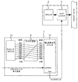
図18はスロットマシン10の電気的な概略構造を示すブロック図である。この図において電源系統についての表示は省略されている。スロットマシン10は、その主要な処理装置としてメイン基板1(第1処理部)とこれからコマンドを受けて動作するサブ基板2(第2処理部)とを備える。なお、少なくともメイン基板1は、外部から接触不能となるようにケース内部に収容され、これら基板を取り外す際に痕跡が残るように封印処理が施されている。
FIG. 18 is a block diagram showing an electrical schematic structure of the
メイン基板1は、遊技者の操作を受けて内部抽選を行ったり、リールの回転・停止やメダルの払い出しなどの処理を行うためのものである。メイン基板1は、予め設定されたプログラムに従って制御動作を行うCPUと、前記プログラムを記憶する記憶手段であるROMおよび処理結果などを一時的に記憶するRAMを含む。メイン基板1は、後述の乱数発生部20に対して所定の条件の下で乱数更新の停止を指令する信号を発生する更新停止信号発生器1aを含む。これは例えばソフトウエアにより実現され、この場合この処理はメイン基板1のCPUにより実行される。メイン基板1のROMにはこの処理を行うためのプログラムが予め書き込まれている。更新停止信号発生器1aについては後に詳しく説明する。
The
サブ基板2は、メイン基板1からコマンド信号を受けて内部抽選の結果を報知したり各種演出を行うためのものである。サブ基板2は、前記コマンド信号に応じた予め設定されたプログラムに従って制御動作を行うCPUと、前記プログラムを記憶する記憶手段であるROMおよび処理結果などを一時的に記憶するRAMを含む。
The
サブ基板2はメイン基板1からコマンドをうけ、これに従って演出等の処理を行う。コマンドの流れはメイン基板1からサブ基板2への一方のみであり、逆にサブ基板2からメイン基板1へコマンド等が出されることはない。
The
なお、図18において更新停止信号発生器1aをメイン基板1に内蔵させたり、これをメイン基板1で実現するような形で表現しているが、本発明はこれに限定されない。更新停止信号発生器1aをメイン基板1に付加する、マイコンを用いたファームウエアも含むハードウエアの形で実現するようにしてもよい。
In FIG. 18, the update
メイン基板1には乱数発生部20、スタートスイッチ30,ストップスイッチ50,リール駆動部70,リール位置検出回路71、ホッパー駆動部80、ホッパー81及びホッパー81から払い出されたメダルの枚数を数えるためのメダル検出部82が接続されている。サブ基板2には液晶表示装置62の制御基板200、スピーカ201、LED基板202などの周辺基板(ローカル基板)が接続されている。以下、スタートスイッチ30,ストップスイッチ50を除く、これらの周辺基板/装置について説明する。
To count the number of medals paid out from the
乱数発生部20は、一定範囲の数値を高速更新することで擬似的な乱数を発生させる乱数発生機能と、発生した乱数の中から任意の乱数を遊技者の操作を受けて抽出するサンプリング機能を備えるものである。具体例を挙げればカウンタとラッチで構成されるものである。
The random
リール駆動部70は、3つのリール40を回転駆動する図示しないステッピングモータを駆動する回路である。各ステッピングモータはリール駆動回路70によって1−2相励磁されており、所定数のパルスの駆動信号が供給されるとそれぞれ1回転する。
The
リール位置検出回路71は、リール40の近傍に設けられてリール40の回転位置を検出するための図示しないフォトインタラプタから出力パルス信号を受け、3つのリール40それぞれの回転位置を検出し、その検出信号を出力するものである。図示しないフォトインタラプタは各リール40が一回転する毎に各リール40に設けられた遮蔽板を検出してリセットパルスを発生する。このリセットパルスはリール位置検出回路71を介してメイン基板1のCPUに与えられる。メイン基板1のRAM内には、各リール40について一回転の範囲内における回転位置に対応した計数値が格納されており、CPUはリセットパルスを受け取ると、RAM内に形成されたこの計数値を“0”にクリアする。このクリア処理により、各シンボルの移動表示と各ステッピングモータの回転との間に生じるずれが、一回転毎に解消されている。
The reel
ホッパー駆動部80は、メダルを収納するとともに指示された入賞に応じた枚数のメダルを払い出すホッパー81のモーターを駆動する回路である。
The
メダル検出部82は、ホッパー81から払い出されるメダル数を計数するためのものである。メイン基板1のCPUは、このメダル検出部82から受けた実際に払い出しのあったメダル計数値が入賞に応じた所定の配当枚数データに達した時に、ホッパー駆動部80による駆動を停止させ、メダル払い出しを終了させる。ホッパー駆動回路80,メダル検出部82により、遊技の結果にて得られた入賞に基づいて所定枚数のメダルが遊技者に払い出される。
The
液晶制御基板200は、液晶表示部62を駆動するための回路である。
スピーカ201は、音声や効果音等の音響を発生するためのものである。
LED基板202は、図示しない表示ランプやバックランプを駆動するための回路である。
The liquid
The
The
液晶制御基板200により表示制御される液晶表示装置62、スピーカ201や表示ランプ等を含むLED基板202は演出表示装置を構成する。この演出表示装置は、遊技者に入賞等を報知したり、いわゆるアシストタイム(AT)において、一定ゲーム間に特定の小役を台自体が何らかのアクションを伴ってユーザに教えるためのものである。
The liquid
図19において、1a−1は更新停止信号発生器の一例としてのフリップフロップ回路である。この回路1a−1のセット端子には任意のひとつのストップスイッチ50が押し下げられたときの信号が入力され(あるいは複数のスイッチ50の出力の論理和をとった信号でもよい)、同じくリセット端子には回転リール(回胴とも呼ぶ)40の停止信号が入力される(あるいは複数の回転リール40の停止出力の論理和をとった信号でもよい)。したがって、フリップフロップ回路1a−1はストップスイッチ押下信号によりカウント停止信号を発生させ、回転リール(回胴)停止信号によりカウント停止信号を解除し、カウンタ1a(あるいはカウンタ1b)にカウントを再開させる。
In FIG. 19, 1a-1 is a flip-flop circuit as an example of an update stop signal generator. The set terminal of the
図19はハードウエア的ブロック図を示したが、これはソフトウエア的にも実現できる。 FIG. 19 shows a hardware block diagram, but this can also be realized by software.
このように、タイミングカウンタ1aの停止から再開までの時間は、回転リール(回胴)40の停止の時間に対応する。ひとつの回転リール40の停止時間は約7.5ms〜190msであるが、これは停止ボタンを押すタイミングや内部抽選の結果などに関係し、毎回異なる。言い換えれば、回転リール40の停止時間は常に揺らぐので、これを揺らぎ信号として利用することができる。1つの回転リール40による揺らぎの幅は約183msである。3つの回転リール40全体について言えばその停止時間は約22.5ms〜570msであり、揺らぎの幅は約548msとなる。
Thus, the time from the stop of the
このことを図20のタイミングチャートを用いて説明する。同図はタイミングカウンタの動作を停止する場合を示す。同図において、ストップスイッチ押下信号がt2に発生し、回転リールがt3に停止している。t2からt3にかけてカウント停止信号が出力され、カウンタの動作は停止する。t2からt3にかけてのゆらぎTは滑りコマ数と呼ばれるもので、上記揺らぎの幅に相当する。同図のタイミングカウンタの値はカウント停止信号がないときは標準繰返周期で繰り返され、その予測は容易である。しかし、カウント停止信号により繰返周期は、標準繰返周期にゆらぎTを加えた時間になり、標準繰返周期とは大きくずれてしまう。したがってカウンタの値の予測は困難になる。 This will be described with reference to the timing chart of FIG. This figure shows a case where the operation of the timing counter is stopped. In the drawing, a stop switch pressing signal is generated at t2, and the rotating reel is stopped at t3. A count stop signal is output from t2 to t3, and the operation of the counter stops. The fluctuation T from t2 to t3 is called the number of sliding frames, and corresponds to the fluctuation width. When there is no count stop signal, the value of the timing counter shown in the figure is repeated at the standard repetition cycle, and the prediction is easy. However, due to the count stop signal, the repetition period is a time obtained by adding fluctuation T to the standard repetition period, and is greatly deviated from the standard repetition period. Therefore, it is difficult to predict the counter value.
理解を容易にするために、回転リール(回胴)の具体的構成について説明を加える。
図21に示すように、各リール40a〜40cは回転リールユニットとして構成されており、フレーム151にブラケット152を介して取り付けられている。各リール40a〜40cはリールドラム153の外周にリール帯154が貼られて構成されている。リール帯154の外周面には上記のシンボル列(図柄61)が描かれている。また、各ブラケット152にはステッピングモータ155が設けられており、各リール40a〜40cはこれらモータ155で駆動されて回転する。
In order to facilitate understanding, a specific configuration of the rotating reel (rotating drum) will be described.
As shown in FIG. 21, each of the
各リール40a〜40cの構造は図22(a)に示される。リール帯154の背後のリールドラム153内部にはランプケース156が設けられており、このランプケース156の3個の各部屋にはそれぞれバックランプ157a,157b,157cが取り付けられている。これらバックランプ157a〜157cは図22(b)に示すように基板158に実装されており、この基板158がランプケース156の背後に取り付けられている。また、ブラケット152にはフォトインタラプタ159が取り付けられている。フォトインタラプタとは、1つのケースの中に発光素子(発光ダイオードなど)と受光素子(フォトトランジスタ、フォトダイオードなど)を対向配置し、その間に検出用の溝を設け、当該検出溝間を物体が通過したことを非接触で検知するものである。このフォトインタラプタ159は、リールドラム153に設けられた遮蔽板160がリールドラム153の回転に伴ってフォトインタラプタ159を通過するのを検出する。フォトインタラプタ159の信号が図2のリール位置検出回路71に入力される。
The structure of each
各バックランプ157a〜157cは図示しないランプ駆動回路によって個別に点灯制御される。各バックランプ157a〜157cの点灯により、リール帯154に描かれたシンボルの内、各バックランプ157の前部に位置する3個のシンボルが背後から個別に照らし出され、図柄表示窓13にそれぞれ3個ずつのシンボルが映し出される。
The
スタートレバー30のレバー操作により、リール40a〜40cが一斉に回転する。3つの停止ボタン50〜50は、各リール40a〜40cに対応して配置されている。各リール40a〜40cの回転速度が一定速度に達したときに各停止ボタン50〜50の操作が有効化され、各停止ボタン50〜50は遊技者の押しボタン操作に応じて各リール40a〜40cの回転を停止させる。
By operating the
リール位置検出回路は、フォトインタラプタ159からの出力パルス信号を受けて各リール40の回転位置を検出する。フォトインタラプタ159は各リール40が一回転する毎に遮蔽板60を検出してリセットパルスを発生する。このリセットパルスはリール位置検出回路を介してメイン基板に与えられる。メイン基板のRAM内には、各リール40について、一回転の範囲内における回転位置に対応した計数値が格納されており、メイン基板のCPUはリセットパルスを受け取ると、RAM内に形成されたこの計数値を“0”にクリアする。このクリア処理により、各シンボルの移動表示と各ステッピングモータ155の回転との間に生じるずれが、一回転毎に解消されている。ストップスイッチ50が押された時に、対応するリール40を停止させる信号がメイン基板に送られる。
The reel position detection circuit receives the output pulse signal from the
(5)
これは、メイン基板1におけるサブコマンド送信要求に基づき乱数更新を停止させ、サブコマンド送信開始に応じて更新を再開させるというものである。(1)〜(4)はいずれも遊技者の操作と関連するものであったが、(5)は装置の内部処理のみを契機とするものである。本発明は装置の内部処理を契機とするものも含む。サブコマンド送信要求を受けてから実際にサブコマンドを送信するまでの時間は、CPUの処理状況により毎回異なる。例えば、0乃至36msの間で変化する。この時間は揺らぎとして利用することができる。図23にタイミングチャートを示す。サブコマンド送信要求がt10に発生し、サブコマンドの送信開始がt11であるとき、t10からt11までの時間:遅延Tが揺らぎとなり、このときのタイミングカウンタの繰り返し周期は標準繰返周期に遅延Tを加えたものになる。
(5)
This is to stop the random number update based on the subcommand transmission request in the
発明の実施の形態4.
上記各発明の実施の形態は、カウンタにより構成される乱数発生器2の出力を乱数とするものであったが、乱数発生器2の出力を乱数の種として用い公知のアルゴリズム(例えば線形合同法、MT法、平均採中法、指数乱数列など)を用いて乱数を発生するようにしてもよい。
In the above embodiments of the invention, the output of the
この例を図24に示す。タイマカウンタ2aは所定のクロックに基づきカウントアップ(カウントダウン)動作を継続して行う。乱数発生器2bは、乱数抽出器3(カウンタタイマ2aの出力のラッチ)の出力を乱数の種として公知のアルゴリズムを用いて乱数を発生する。この出力に基づき抽選が行われる。揺らぎ発生器1によりラッチのタイミングが揺らぎ、乱数の種はさまざまな値をとるので、発生される乱数系列は同じものになることはなく好ましい。揺らぎ発生器1として前述したカウンタを用いたもの、ビット入替を行うもの、リールの滑りやコマンドの遅延を利用したものを適用可能である。
This example is shown in FIG. The
サブ基板2で乱数を発生させるときは、メイン基板1から送られてくるコマンドの受信タイミングでタイマカウンタ2aの出力をラッチさせるとよい。当該コマンドの受信タイミングにはランダムな時間遅延が生じているので(発明の実施の形態3の(5)の説明参照)、乱数の種が同じ値あるいは規則的な値をとる可能性が低くなる。この場合、コマンド送受信そのものが揺らぐので揺らぎ発生器1を特別に設ける必要はない。いわばメイン基板1とサブ基板2の通信手順そのものが揺らぎ発生器1に相当する。特許請求の範囲に記載された揺らぎ発生器は、このようなものも含む趣旨である。
When generating a random number in the
上記各発明の実施の形態で説明した揺らぎ発生器は、メイン基板1における抽選手段ばかりでなく、サブ基板2における抽選手段にも適用できる。特許請求の範囲に記載された入賞抽選手段は、メイン基板1とサブ基板2のいずれか一方あるいは両方に設けられてもよい。いずれの場合も本発明に含まれるものである。
The fluctuation generator described in the above embodiments of the present invention can be applied not only to the lottery means on the
本発明は、以上の実施の形態に限定されることなく、特許請求の範囲に記載された発明の範囲内で、種々の変更が可能であり、それらも本発明の範囲内に包含されるものであることは言うまでもない。 The present invention is not limited to the above embodiments, and various modifications can be made within the scope of the invention described in the claims, and these are also included in the scope of the present invention. Needless to say.
また、本明細書において、部/手段とは必ずしも物理的手段を意味するものではなく、各部/手段の機能が、ソフトウェアによって実現される場合も包含する。さらに、一つの部/手段の機能が、二つ以上の物理的手段により実現されても、若しくは、二つ以上の部/手段の機能が、一つの物理的手段により実現されてもよい。 In the present specification, the term “unit / means” does not necessarily mean a physical means, but includes cases where the functions of the respective units / means are realized by software. Further, the function of one part / means may be realized by two or more physical means, or the function of two or more parts / means may be realized by one physical means.
1 揺らぎ発生器
1a 揺らぎ発生器のタイミングカウンタ
1b 揺らぎ発生用カウンタ
2 乱数発生器
2a タイマカウンタ
2b 乱数発生器
3 乱数抽出器
4 判定部
5 入賞判定テーブル
6 ビット入替部
10 スロットマシン
11 筐体
12 表示窓
13 図柄表示窓
16 ベットスイッチ
17 精算スイッチ
30 スタートスイッチ
31 コネクタ
32 処理・表示部
33 コネクタ
40 回転リール
42 リールテープ
50 ストップスイッチ
60 リールユニット
61 図柄
62 液晶表示部
100 メダル投入口
304 メダル払い出し口
311 メダル受け部(下皿)
DESCRIPTION OF
Claims (3)
前記入賞抽選手段は、抽選を行うための前記スタートスイッチの信号を受け、前記スタートスイッチの信号に揺らぎを加えて出力する揺らぎ発生器を含み、
前記揺らぎ発生器は、タイミングカウンタと、前記スタートスイッチの信号に基づき前記タイミングカウンタの出力を読み込み、読み込んだ値を元にカウントを行う揺らぎ発生用カウンタと、前記タイミングカウンタに対して所定の契機でカウントの停止及び再開を指示する更新停止信号発生器とを備え、
前記揺らぎ発生用カウンタの桁上がり信号が揺らぎの加えられた信号として出力され、
前記入賞抽選手段は、揺らぎの加えられた前記信号に基づき抽選を行い、
前記更新停止信号発生器は、前記複数のストップスイッチのいずれかが押下されたとき前記タイミングカウンタに対してカウントの停止を指示し、
前記回転リールが停止したとき前記タイミングカウンタに対してカウントの再開を指示することを特徴とするスロットマシン。 A lottery means for performing a lottery based on a signal from a start switch operated by a player and determining a prize based on the lottery result, a plurality of rotating reels, a reel driving unit for rotating the plurality of rotating reels, and the plurality A reel position detection circuit for detecting a rotation position of the rotation reel, a plurality of stop switches for stopping the rotation of the plurality of rotation reels, the reel drive unit and the reel position detection circuit, and the start switch And a control device that controls rotation and stop of the plurality of rotating reels based on signals from the plurality of stop switches ,
The winning lottery means includes a fluctuation generator that receives a signal of the start switch for performing the lottery and outputs a fluctuation to the signal of the start switch ,
The fluctuation generator reads a timing counter, an output of the timing counter based on a signal of the start switch, and performs a count based on the read value, and a fluctuation generation counter that performs a predetermined trigger on the timing counter. and a renewal stop signal generator for indicating count the resume stop及beauty,
The carry signal of the fluctuation generating counter is output as signal applied with fluctuations,
The winning lottery means performs a lottery based on the signal subjected to fluctuation,
The update stop signal generator instructs the timing counter to stop counting when any of the plurality of stop switches is pressed ,
A slot machine that instructs the timing counter to resume counting when the rotating reel stops .
前記スタートスイッチの信号を受けて、前記スタートスイッチの信号に揺らぎを加える第1ステップと、
乱数を発生する第2ステップと、
前記第2ステップで発生された乱数の中から前記第1ステップで揺らぎの加えられた信号に基づき乱数を抽出する第3ステップと、
予め用意された入賞判定テーブルを参照して前記第3ステップで抽出された乱数の入賞の有無及び又は入賞の種類を判定する第4ステップとを備え、
前記第1ステップでは、
前記スタートスイッチの信号に基づきタイミングカウンタの出力を読み込み、読み込んだ値を元に揺らぎ発生用カウンタでカウントを行い、前記揺らぎ発生用カウンタの桁上がり信号が前記揺らぎの加えられた信号として出力され、
前記複数のストップスイッチのいずれかが押下されたとき前記タイミングカウンタでのカウントを停止し、
前記回転リールが停止したとき前記タイミングカウンタでのカウントを再開する、ことを特徴とするスロットマシンの入賞判定方法。 A lottery means for performing a lottery based on a signal from a start switch operated by a player and determining a prize based on the lottery result, a plurality of rotating reels, a reel driving unit for rotating the plurality of rotating reels, and the plurality A reel position detection circuit for detecting a rotation position of the rotation reel, a plurality of stop switches for stopping the rotation of the plurality of rotation reels, the reel drive unit and the reel position detection circuit, and the start switch And a method for determining a prize in a slot machine comprising a control device for controlling rotation and stop of the plurality of rotating reels based on signals from the plurality of stop switches ,
A first step of receiving a signal from the start switch and adding a fluctuation to the signal from the start switch ;
A second step of generating a random number;
A third step of extracting a random number from the random number generated in the second step based on the signal added with the fluctuation in the first step;
A fourth step of determining the presence / absence of the random number extracted in the third step and / or the type of the winning with reference to a winning determination table prepared in advance,
In the first step,
Based on the signal of the start switch , the output of the timing counter is read, the counter for fluctuation generation is counted based on the read value, and the carry signal of the counter for fluctuation generation is output as the signal with the fluctuation added,
When any of the plurality of stop switches is pressed , the counting by the timing counter is stopped,
A slot machine winning determination method, characterized in that counting by the timing counter is resumed when the rotating reel stops .
前記スタートスイッチの信号を受けて、前記スタートスイッチの信号に揺らぎを加える第1ステップと、
乱数を発生する第2ステップと、
前記第2ステップで発生された乱数の中から前記第1ステップで揺らぎの加えられた信号に基づき乱数を抽出する第3ステップと、
予め用意された入賞判定テーブルを参照して前記第3ステップで抽出された乱数の入賞の有無及び又は入賞の種類を判定する第4ステップとを備え、
前記第1ステップでは、
前記スタートスイッチの信号に基づきタイミングカウンタの出力を読み込み、読み込んだ値を元に揺らぎ発生用カウンタでカウントを行い、前記揺らぎ発生用カウンタの桁上がり信号が前記揺らぎの加えられた信号として出力され、
前記複数のストップスイッチのいずれかが押下されたとき前記タイミングカウンタでのカウントを停止し、
前記回転リールが停止したとき前記タイミングカウンタでのカウントを再開する、ことを特徴とするプログラム。 A lottery means for performing a lottery based on a signal from a start switch operated by a player and determining a prize based on the lottery result, a plurality of rotating reels, a reel driving unit for rotating the plurality of rotating reels, and the plurality A reel position detection circuit for detecting a rotation position of the rotation reel, a plurality of stop switches for stopping the rotation of the plurality of rotation reels, the reel drive unit and the reel position detection circuit, and the start switch And a program for causing a computer to execute a method for determining a prize in a slot machine comprising a control device that controls rotation and stop of the plurality of rotating reels based on signals from the plurality of stop switches ,
A first step of receiving a signal from the start switch and adding a fluctuation to the signal from the start switch ;
A second step of generating a random number;
A third step of extracting a random number from the random number generated in the second step based on the signal added with the fluctuation in the first step;
A fourth step of determining the presence / absence of the random number extracted in the third step and / or the type of the winning with reference to a winning determination table prepared in advance,
In the first step,
Based on the signal of the start switch , the output of the timing counter is read, the counter for fluctuation generation is counted based on the read value, and the carry signal of the counter for fluctuation generation is output as the signal with the fluctuation added,
When any of the plurality of stop switches is pressed , the counting by the timing counter is stopped,
A program for resuming counting by the timing counter when the rotating reel is stopped .
Priority Applications (1)
| Application Number | Priority Date | Filing Date | Title |
|---|---|---|---|
| JP2003367628A JP4340125B2 (en) | 2003-04-11 | 2003-10-28 | Slot machine, winning determination method and program for slot machine |
Applications Claiming Priority (2)
| Application Number | Priority Date | Filing Date | Title |
|---|---|---|---|
| JP2003108343 | 2003-04-11 | ||
| JP2003367628A JP4340125B2 (en) | 2003-04-11 | 2003-10-28 | Slot machine, winning determination method and program for slot machine |
Related Child Applications (1)
| Application Number | Title | Priority Date | Filing Date |
|---|---|---|---|
| JP2006229948A Division JP4054356B2 (en) | 2003-04-11 | 2006-08-26 | Slot machine, winning determination method and program for slot machine |
Publications (3)
| Publication Number | Publication Date |
|---|---|
| JP2004321773A JP2004321773A (en) | 2004-11-18 |
| JP2004321773A5 JP2004321773A5 (en) | 2006-10-12 |
| JP4340125B2 true JP4340125B2 (en) | 2009-10-07 |
Family
ID=33513098
Family Applications (1)
| Application Number | Title | Priority Date | Filing Date |
|---|---|---|---|
| JP2003367628A Expired - Fee Related JP4340125B2 (en) | 2003-04-11 | 2003-10-28 | Slot machine, winning determination method and program for slot machine |
Country Status (1)
| Country | Link |
|---|---|
| JP (1) | JP4340125B2 (en) |
Families Citing this family (4)
| Publication number | Priority date | Publication date | Assignee | Title |
|---|---|---|---|---|
| JP4149433B2 (en) * | 2004-12-02 | 2008-09-10 | 株式会社三共 | Slot machine |
| JP4843240B2 (en) * | 2005-03-25 | 2011-12-21 | 株式会社三共 | Slot machine |
| JP4749485B2 (en) * | 2009-08-19 | 2011-08-17 | 株式会社三共 | Slot machine |
| JP5079070B2 (en) * | 2010-11-17 | 2012-11-21 | 株式会社三共 | Slot machine |
-
2003
- 2003-10-28 JP JP2003367628A patent/JP4340125B2/en not_active Expired - Fee Related
Also Published As
| Publication number | Publication date |
|---|---|
| JP2004321773A (en) | 2004-11-18 |
Similar Documents
| Publication | Publication Date | Title |
|---|---|---|
| JP6528201B2 (en) | Game console | |
| JP5679294B2 (en) | Slot machine | |
| JP6159311B2 (en) | Amusement stand | |
| JP2006239319A (en) | Game machine, winning judgment method of game machine and program | |
| JP2005027819A (en) | Game machine, and method and program for command communication in game machine | |
| JP2004313622A (en) | Game machine | |
| JP4340125B2 (en) | Slot machine, winning determination method and program for slot machine | |
| JP4409908B2 (en) | Slot machine | |
| JP4848064B2 (en) | Game machine | |
| JP4669588B2 (en) | Game machine | |
| JP4054356B2 (en) | Slot machine, winning determination method and program for slot machine | |
| JP4663025B2 (en) | Slot machine | |
| JP4054293B2 (en) | Slot machine, winning determination method and program for slot machine | |
| JP5533681B2 (en) | Game machine | |
| JP4058082B2 (en) | Slot machine, winning determination method and program for slot machine | |
| JP6528202B2 (en) | Game console | |
| JP2007117643A (en) | Game machine | |
| JP4818445B2 (en) | Slot machine | |
| JP2008245867A (en) | Game machine, and random number generation method and program for lottery of it | |
| JP2005007139A (en) | Game machine, prize winning determination method thereof, and program | |
| JP2008113914A (en) | Game machine, method for determining prize winning of game machine, and program | |
| JP2008110127A (en) | Game machine | |
| JP2004016471A (en) | Game machine, program, and memory medium | |
| JP4141982B2 (en) | Slot machine | |
| JP4980754B2 (en) | Game machine |
Legal Events
| Date | Code | Title | Description |
|---|---|---|---|
| A621 | Written request for application examination |
Free format text: JAPANESE INTERMEDIATE CODE: A621 Effective date: 20041112 |
|
| A521 | Written amendment |
Free format text: JAPANESE INTERMEDIATE CODE: A523 Effective date: 20060826 |
|
| A131 | Notification of reasons for refusal |
Free format text: JAPANESE INTERMEDIATE CODE: A131 Effective date: 20070508 |
|
| A521 | Written amendment |
Free format text: JAPANESE INTERMEDIATE CODE: A523 Effective date: 20070705 |
|
| A131 | Notification of reasons for refusal |
Free format text: JAPANESE INTERMEDIATE CODE: A131 Effective date: 20070927 |
|
| A521 | Written amendment |
Free format text: JAPANESE INTERMEDIATE CODE: A523 Effective date: 20071115 |
|
| A02 | Decision of refusal |
Free format text: JAPANESE INTERMEDIATE CODE: A02 Effective date: 20071211 |
|
| A01 | Written decision to grant a patent or to grant a registration (utility model) |
Free format text: JAPANESE INTERMEDIATE CODE: A01 |
|
| A61 | First payment of annual fees (during grant procedure) |
Free format text: JAPANESE INTERMEDIATE CODE: A61 Effective date: 20090703 |
|
| R150 | Certificate of patent or registration of utility model |
Free format text: JAPANESE INTERMEDIATE CODE: R150 |
|
| FPAY | Renewal fee payment (event date is renewal date of database) |
Free format text: PAYMENT UNTIL: 20120710 Year of fee payment: 3 |
|
| FPAY | Renewal fee payment (event date is renewal date of database) |
Free format text: PAYMENT UNTIL: 20120710 Year of fee payment: 3 |
|
| FPAY | Renewal fee payment (event date is renewal date of database) |
Free format text: PAYMENT UNTIL: 20130710 Year of fee payment: 4 |
|
| R250 | Receipt of annual fees |
Free format text: JAPANESE INTERMEDIATE CODE: R250 |
|
| S531 | Written request for registration of change of domicile |
Free format text: JAPANESE INTERMEDIATE CODE: R313531 |
|
| R350 | Written notification of registration of transfer |
Free format text: JAPANESE INTERMEDIATE CODE: R350 |
|
| R250 | Receipt of annual fees |
Free format text: JAPANESE INTERMEDIATE CODE: R250 |
|
| R250 | Receipt of annual fees |
Free format text: JAPANESE INTERMEDIATE CODE: R250 |
|
| R250 | Receipt of annual fees |
Free format text: JAPANESE INTERMEDIATE CODE: R250 |
|
| LAPS | Cancellation because of no payment of annual fees |