JP4339217B2 - Setting value determination device - Google Patents
Setting value determination device Download PDFInfo
- Publication number
- JP4339217B2 JP4339217B2 JP2004271313A JP2004271313A JP4339217B2 JP 4339217 B2 JP4339217 B2 JP 4339217B2 JP 2004271313 A JP2004271313 A JP 2004271313A JP 2004271313 A JP2004271313 A JP 2004271313A JP 4339217 B2 JP4339217 B2 JP 4339217B2
- Authority
- JP
- Japan
- Prior art keywords
- cover factor
- woven fabric
- loom
- weaving
- information
- Prior art date
- Legal status (The legal status is an assumption and is not a legal conclusion. Google has not performed a legal analysis and makes no representation as to the accuracy of the status listed.)
- Expired - Fee Related
Links
- 238000009941 weaving Methods 0.000 claims description 83
- 239000002759 woven fabric Substances 0.000 claims description 52
- 230000002265 prevention Effects 0.000 claims description 41
- 239000004744 fabric Substances 0.000 claims description 29
- 230000035515 penetration Effects 0.000 claims description 3
- 238000004804 winding Methods 0.000 description 31
- 238000003780 insertion Methods 0.000 description 18
- 230000037431 insertion Effects 0.000 description 18
- 238000012545 processing Methods 0.000 description 14
- 238000000034 method Methods 0.000 description 13
- 230000006870 function Effects 0.000 description 10
- 235000014676 Phragmites communis Nutrition 0.000 description 8
- 230000007246 mechanism Effects 0.000 description 5
- 238000012937 correction Methods 0.000 description 4
- 238000010009 beating Methods 0.000 description 3
- 238000004364 calculation method Methods 0.000 description 3
- 230000008439 repair process Effects 0.000 description 3
- 238000009736 wetting Methods 0.000 description 3
- 230000008859 change Effects 0.000 description 2
- 238000010586 diagram Methods 0.000 description 2
- 238000006073 displacement reaction Methods 0.000 description 2
- 230000000694 effects Effects 0.000 description 2
- 230000008569 process Effects 0.000 description 2
- 230000009467 reduction Effects 0.000 description 2
- 238000010187 selection method Methods 0.000 description 2
- 230000009897 systematic effect Effects 0.000 description 2
- 229920000742 Cotton Polymers 0.000 description 1
- 244000089486 Phragmites australis subsp australis Species 0.000 description 1
- 230000004913 activation Effects 0.000 description 1
- 230000007812 deficiency Effects 0.000 description 1
- 238000007726 management method Methods 0.000 description 1
- 238000004519 manufacturing process Methods 0.000 description 1
- 238000012986 modification Methods 0.000 description 1
- 230000004048 modification Effects 0.000 description 1
- 238000005086 pumping Methods 0.000 description 1
- 238000011160 research Methods 0.000 description 1
- 230000004044 response Effects 0.000 description 1
- 238000005096 rolling process Methods 0.000 description 1
- 230000002195 synergetic effect Effects 0.000 description 1
- 230000001052 transient effect Effects 0.000 description 1
- 210000002268 wool Anatomy 0.000 description 1
Images


Classifications
-
- D—TEXTILES; PAPER
- D03—WEAVING
- D03C—SHEDDING MECHANISMS; PATTERN CARDS OR CHAINS; PUNCHING OF CARDS; DESIGNING PATTERNS
- D03C1/00—Dobbies
- D03C1/14—Features common to dobbies of different types
- D03C1/146—Independent drive motor
-
- D—TEXTILES; PAPER
- D03—WEAVING
- D03D—WOVEN FABRICS; METHODS OF WEAVING; LOOMS
- D03D51/00—Driving, starting, or stopping arrangements; Automatic stop motions
-
- D—TEXTILES; PAPER
- D03—WEAVING
- D03D—WOVEN FABRICS; METHODS OF WEAVING; LOOMS
- D03D51/00—Driving, starting, or stopping arrangements; Automatic stop motions
- D03D51/002—Avoiding starting marks
-
- D—TEXTILES; PAPER
- D03—WEAVING
- D03J—AUXILIARY WEAVING APPARATUS; WEAVERS' TOOLS; SHUTTLES
- D03J1/00—Auxiliary apparatus combined with or associated with looms
- D03J1/005—Displays or displaying data
Description
本発明は、織布に関する情報に基づいて、織機の織段防止装置の動作態様の設定値を決定する技術に関する。 The present invention relates to a technique for determining a setting value of an operation mode of a weaving step prevention device for a loom based on information about a woven fabric.
織機の織段防止装置の1つとして、織機の起動に先立ち、ワープビーム又は巻取ロールを所定の回転角度だけ正転又は逆転させて、織前を所定の位置に変位させる、いわゆるキックバック動作を行う装置が知られている(例えば、特許文献1参照)。 As one of the weaving step prevention devices of a loom, a so-called kickback operation in which a warp beam or a take-up roll is rotated forward or backward by a predetermined rotation angle to displace the front of the weaving to a predetermined position before starting the loom. There is known an apparatus for performing (see, for example, Patent Document 1).
また、多色緯入れ織機の織段防止装置として、緯糸のカラーパターン毎に、織前の位置を補正する補正量を予め設定しておき、織機の再起動を行うときに、その緯糸のカラーパターンに対応する補正量に従って、ワープビーム又は巻取ロールを所定の回転角度だけ正転又は逆転させて、織前を所定の位置に変位させる、いわゆるキックバック動作を行う装置が知られている(例えば、特許文献2参照)。 Also, as a weaving step prevention device for a multi-color weft insertion loom, a correction amount for correcting the position before weaving is set in advance for each weft color pattern, and when the loom is restarted, the color of the weft There is known a device that performs a so-called kickback operation in which a warp beam or a winding roll is rotated forward or reverse by a predetermined rotation angle according to a correction amount corresponding to a pattern, and the front of the weave is displaced to a predetermined position ( For example, see Patent Document 2).
しかし、これらの織段防止装置の動作態様の設定は、作業者の経験に基づいて行われ、しかも作業者が実際の織布に織段が発生しているか否かを確認しながら行われるから、作業者が最適値を見つけるまでの時間が長い。 However, since the setting of the operation mode of these weaving step prevention devices is performed based on the experience of the worker, and the worker confirms whether or not the weaving step has occurred in the actual woven fabric. It takes a long time for the operator to find the optimum value.
したがって、作業者の経験に基づく織段防止装置の設定方法は、作業者が織段防止装置の設定を調整する作業に多くの時間を費やすから、良質な織布の生産効率が低くなるという問題を有する。 Therefore, the setting method of the weaving prevention device based on the experience of the operator spends a lot of time on the work of adjusting the setting of the weaving prevention device, so that the production efficiency of high quality woven fabric is low. Have
本発明の目的は、織物の仕様に適した、織段防止装置の動作態様を設定するための情報を作業者に提供することにある。 An object of the present invention is to provide an operator with information for setting an operation mode of a weaving prevention apparatus suitable for the specification of a fabric.
本発明に係る設定値決定装置は、織布に関する情報が入力される入力器と、織機の織段防止装置の動作態様の設定値を決定して出力する出力器とを含む。前記織布に関する情報は、さらに、前記織布の糸の込み具合を示すカバーファクタ、又は該カバーファクタの元になる値を含む。前記出力器は、少なくともカバーファクタに基づいて、前記設定値を決定して出力することを含む。 The set value determination device according to the present invention includes an input device to which information relating to a woven fabric is input, and an output device to determine and output a set value of an operation mode of the weaving step prevention device of the loom. The information regarding the woven fabric further includes a cover factor indicating the degree of thread penetration of the woven fabric or a value based on the cover factor. The output unit includes determining and outputting the set value based on at least a cover factor.
ここで、糸の込み具合を示すカバーファクタをCFで示すと、カバーファクタCFは、カバーファクタCF=経のカバーファクタCFw+緯のカバーファクタCFpで示される。ただし、経のカバーファクタCFw=A×2.54/√B、緯のカバーファクタCFp=C/√Dである。パラメータAは単位織幅長さ当たりの経糸本数、パラメータBは経糸太さ(番手)、パラメータCは設定打込密度、Dは緯糸太さ(番手)を示す。 Here, when the cover factor indicating the degree of thread insertion is represented by CF, the cover factor CF is represented by cover factor CF = warp cover factor CFw + weft cover factor CFp. However, the warp cover factor CFw = A × 2.54 / √B and the weft cover factor CFp = C / √D. Parameter A represents the number of warps per unit woven width length, parameter B represents the warp thickness (count), parameter C represents the set driving density, and D represents the weft thickness (count).
具体的には、パラメータAは経糸の総本数/筬通し幅で求められる。よって、パラメータAは、経糸の総本数と筬通し幅とに基づいて算出される。 Specifically, the parameter A is obtained by the total number of warps / the threading width. Therefore, the parameter A is calculated based on the total number of warps and the threading width.
本発明によれば、織段防止装置の動作態様の設定値は、少なくともカバーファクタに基づいて決定される。したがって、織物品種換わり等により織布の仕様が変更された場合であっても、作業者は、カバーファクタ又はカバーファクタのもとになる値を入力器に入力すれば、出力器は、少なくともカバーファクタが加味された織段防止装置の動作態様の設定値を自動的に出力することができ、織段防止装置に設定することができる。 According to the present invention, the set value of the operation mode of the weaving stage preventing apparatus is determined based on at least the cover factor. Therefore, even if the specification of the woven fabric is changed due to the change of the fabric type or the like, if the operator inputs the cover factor or the value based on the cover factor to the input device, the output device will at least cover. The set value of the operation mode of the weaving stage preventing apparatus with the factor added can be automatically output, and can be set in the weaving stage preventing apparatus.
しかも、設定値決定装置がそのように出力する出力情報としての設定値は、カバーファクタが加味されて決定されるため、従来に比べ、緯糸の打込の難易性が考慮された織段防止装置の動作態様の設定値である。したがって、製織経験の少ない作業者であっても、織段のない良質な織布を直ちに生産することができる。 Moreover, since the set value as the output information output by the set value determining device is determined in consideration of the cover factor, the weaving step preventing device considering the difficulty in driving the weft yarn as compared with the conventional one. Is the set value of the operation mode. Therefore, even an operator with little weaving experience can immediately produce a high-quality woven fabric without a weaving step.
なぜなら、作業者は、従来のように緯糸の打込の難易性が考慮された最適な動作態様を見つけるまで試行錯誤を長い期間繰り返す必要がないから、このような調整に係わる時間を短縮できるからである。 This is because the operator does not have to repeat trial and error for a long period until he finds the optimum operation mode that takes into account the difficulty of driving in the weft as in the prior art, and thus the time required for such adjustment can be shortened. It is.
前記織布に関する情報としてのカバーファクタの元になる値は、単位織幅当たりの経糸の本数、経糸の太さ、緯糸の打込密度及び緯糸の太さに関する値を含み、前記出力器は、前記カバーファクタの元になる複数の値に基づいてカバーファクタを算出し、少なくとも前記算出したカバーファクタに基づいて、前記設定値を決定して出力することを含むようにしてもよい。 The base value of the cover factor as information on the woven fabric includes values relating to the number of warps per unit woven width, the thickness of the warp, the wetting density of the wefts, and the thickness of the wefts. The method may include calculating a cover factor based on a plurality of values based on the cover factor, and determining and outputting the set value based on at least the calculated cover factor.
前記織布に関する情報は、さらに、織物種類又は織物組織に関する情報を含み、前記出力器は、前記織物種類又は織物組織に関する情報のうち少なくとも1つと、前記カバーファクタとに基づいて、前記設定値を決定して出力することを含むようにしてもよい。 The information on the woven fabric further includes information on a woven fabric type or a woven fabric structure, and the output device sets the set value based on at least one of the information on the woven fabric type or the woven fabric and the cover factor. It may include determining and outputting.
前記出力器は、織段防止動作における複数の動作態様が前記織布に関する情報に対応されて予め記憶されるデータベースと、前記入力器を介して入力される織布に関する情報に基づいて、前記データベースの中から対応する動作態様の設定値を検索する検索手段とを含むようにしてもよい。 The output device includes a database in which a plurality of operation modes in a weaving step prevention operation are stored in advance corresponding to information on the woven fabric, and the database based on the information on the woven fabric input via the input device. Search means for searching for a set value of a corresponding operation mode from the above.
図1を参照するに、織機10において、経糸12は、これが巻かれているワープビーム14から、バックローラ16、複数の綜絖枠18及び筬20を経て織前22に繋がっている。
Referring to FIG. 1, in a
経糸開口内に緯入れされた緯糸24は、筬20によって織前22に筬打ちされ、織布26となる。
The
織布26は、織前22から、ガイドロール27を経て服巻ロール28に達する。服巻ロール28に達した織布26は、服巻ロール28と一対のプレスロール30とにより布巻ビーム32に送り出される。送り出された織布26は、布巻ビーム32に巻き取られる。
The
ワープビーム14は、送出モータ34により歯車のような減速機構で構成される図示しないギア機構を介して回転されて、複数の経糸12をシートの形で送出する。ワープビーム14に巻かれている経糸12の巻径は、巻径検出器36によって、巻径Dとして検出する。
The
各綜絖枠18は、開口装置37の開口駆動部38により上下に往復移動されて、経糸12を上下に開口させる。開口駆動部38は、主軸モータ40により回転される主軸42の回転運動を受け、その回転運動を各綜絖枠18の往復運動に変換する。
Each
筬20は、主軸42の回転運動を受ける筬打ち駆動部44によりその回転運動が揺動運動に変換されて揺動駆動され、経糸12の開口内に緯入れされた緯糸24を織前22に打ち付ける。
The
服巻ロール28は、巻取モータ46の回転運動を受ける歯車のような減速機構で構成される図示しないギア機構を介して回転される。回転された服巻ロール28は、一対のプレスロール30と共同して織布26を布巻ビーム32に送り出す。
The
主軸42の回転角度は、エンコーダ48によって検出される。検出された主軸42の回転角度は、主軸回転角度θとして、主制御装置50及び送出制御器52に供給される(図2参照)。
The rotation angle of the
図2を参照するに、設定値決定装置54は、入力器及び表示器として作用するタッチパネル56を有する。また、設定値決定装置54は、織段防止動作における複数の動作態様の設定値Tが前記織布に関する情報に対応されて予め記憶されるデータベース58と、データベース58と前記入力器を介して入力される織布に関する情報とに基づいて動作態様の設定値Tを検索するためのプログラムが格納されているメモリ60と、検索手段として作用する中央演算処理装置(CPU)62とを有する。
Referring to FIG. 2, the set
中央演算処理装置62は、タッチパネル56とデータベース58とメモリ60とポート64とに接続している。作業者がタッチパネル56を介して織機10の織布に関する情報を入力情報として入力すると、中央演算処理装置62は、メモリ60からデータベース58を検索するためのプログラムを読み出し、入力した織布に関する情報に基づいて、データベース58から設定値を検索する。
なお、設定値決定装置54は、上記したように織段防止装置78の動作態様の設定値を入力する機能を有するほか、経糸張力制御や緯入れ装置などの図示しない装置へ出力するための設定値を入力したり、織機10の情報を表示したりする、織機10の設定器としての機能も兼ね備えることができる。
The set
中央演算処理装置62は、検索された設定値をタッチパネル56に、作業者に読み取り可能に表示させる。また、中央演算処理装置62は、タッチパネル56に設定値を表示させる、又は表示させると共に、ポート64に出力してもよい。つまり本実施例でいう設定値決定装置54の出力器は、表示器として作用するタッチパネル56,データベース58、メモリ60、中央演算処理装置62のほか、ポート64を含む。
The
主制御装置50は、運転ボタン66、寸動ボタン68、逆転ボタン70、停止ボタン72から出力される運転信号S1、寸動信号S2、逆転信号S3、停止信号S4を受信する。また、主制御装置50は、経糸12や緯糸24が切れたことを検出する糸切れセンサ(図示せず)から出力される停台信号S5を受信する。主制御装置50は、織機10の制御等に用いられるべく設定値決定装置54から出力される複数の設定値Tを受信している。
主制御装置50は、出力する指令信号S8に基づいて送出制御器52、巻取制御器74、開口駆動部38、主軸駆動部76の駆動を制御する機能を有している。また、送出制御器52、巻取制御器74、開口駆動部38、主軸駆動部76は、本実施例の織段防止装置78の駆動回路を構成する。
The
送出制御器52は、主軸回転角度θ、設定値決定装置54から出力される設定値T、主制御装置50から出力される運転指令信号S7及び巻径Dに基づいて、送出モータ34の出力軸の回転を制御する。
The
より詳しくは、送出制御器52は、織機10の運転中には、主制御装置50から出力される運転指令信号S7により経糸張力が目標張力を維持するように送出モータ34の出力軸の回転を制御する。また、送出制御器52は、織機10の停止時、寸動逆転時又は織機10の運転開始時等には、主制御装置50から出力されるフェルコントロール指令、寸動逆転指令又はキックバック指令等の各指令信号S8の発生により、各織段防止動作を遂行すべく送出モータ34の出力軸の回転を制御する。なお、送出制御器52は、これらフェルコントロール指令、寸動逆転指令時における送り量や戻し量、キックバック量などの設定値を、設定値決定装置54としての設定器から直接受ける。
More specifically, during operation of the
巻取制御器74は、主軸回転角度θ、設定値決定装置54から出力される設定値T及び運転指令信号S7に基づいて、巻取モータ46の出力軸の回転を制御する。
The winding
より詳しくは、巻取制御器74は、織機10の運転中には、主制御装置50から出力される運転指令信号S7により織機10の主軸42の回転に同期して巻取モータ46の出力軸の回転を制御する。また、巻取制御器74は、織機10の停止時、寸動逆転時又は織機10の運転開始時等には、主制御装置50から出力されるフェルコントロール指令、寸動逆転指令又はキックバック指令等の各指令信号S8の発生により、各織段防止動作を遂行すべく巻取モータ46の出力軸の回転を制御する。なお、巻取制御器74は、これらフェルコントロール指令、寸動逆転指令時における送り量や戻し量、キックバック量などの設定値を、設定値決定装置54としての設定器から直接受ける。
More specifically, the winding
開口装置37は、例えば、開口駆動部38の駆動軸に、連結可能な単独モータを設けていてもよい。この場合、開口装置37に、開口駆動部38の駆動軸と織機10の主軸42との連結を解いて、油圧シリンダ等のアクチュエータを作動させることにより、各綜絖枠18を中口閉口状態にできるレベリング機構等が構成されている。開口駆動部38は、織機10の運転中には、開口駆動部38の駆動軸を織機10の主軸42に連結して各綜絖枠18を上下動させる。また、開口駆動部38は、織機10の停止時には、主制御装置50から出力されるレベリング指令の指令信号S8に基づいて、レベリング動作である織段防止動作を遂行すべく、上記アクチュエータを作動させて、経糸開口が中口開口となるような位置に綜絖枠18を上下動させる。
For example, the
主軸駆動部76は、主制御装置50から出力される指令信号S8及び回転トルク信号S9に基づいて、主軸モータ40の出力軸ひいては主軸42の回転を制御する。
The main
より詳しくは、主軸駆動部76は、運転開始から所定の期間、織段防止動作を遂行すべく主制御装置50から出力される運転指令信号S7、起動トルク指令、起動トルク切換指令に基づいて、主軸モータ40の出力軸ひいては主軸42を高出力トルクで回転させ、主軸42の回転速度を短時間で高回転速度にして、筬20に筬打ちを行わせる。主軸駆動部76は、主軸40の回転速度が定常回転速度に到達した所定のタイミング以降、主軸42のトルクを定常運転の維持に必要なトルクに低減させる。主軸駆動部76は、このように、一連の駆動制御を遂行する。
More specifically, the
また、主軸駆動部76は、織機10の停止時には、主制御装置50から出力される運転指令信号S1の出力オフにより主軸モータ40の出力軸の回転を停止させる。主軸駆動部76は、織機10の寸動逆転時には、主制御装置50から出力される寸動信号S2又は逆転信号S3により、主軸モータ40の出力軸の回転を寸動信号S2又は逆転信号S3に対応する回転方向に低速駆動させる。
Further, when the
織機10が製織する織物仕掛品が変更されると、作業者は、織機10の機掛け作業を行うと共に、新たな織物に対応する機台条件を織機10の設定器に設定する。このとき、作業者は、その一環として織段防止動作の動作態様も設定する。図3は、機台条件を入力してから、製織運転が開始されるまでの一連の工程を示す。
When the work in progress of the fabric weaved by the
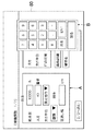
まず、作業者は、設定値決定装置54の入力器としてのタッチパネル56を操作して、織布26における織物の条件を入力する(ST101)。このときのタッチパネル56の画面80の一例を図4及び図5に示す。
First, the operator operates the
図4において、織布に関する情報としての経糸12に関する複数の項目及びその設定値の表示欄が、タッチパネル56の画面80の左側の領域Aに、それぞれ表示されている。また、数値を入力するためのテンキーが図4の右側の領域Bに表示されている。図示の例では、作業者は、先ず領域Aの「筬通し幅」に触れてテンキーを画面80に表示させ、表示されたテンキーを用いて「筬通し幅」の数値を入力しようとしている状態を示している。
In FIG. 4, a plurality of items relating to the
図5は、図4において、「筬通し幅」の値として「190」を入力した状態を示す。また、経糸12に関する情報を示している左側の領域Aには、カバーファクタ算出のもとになる経糸12の情報として、「総本数」は「10000」本、「太さ」は「40」番手がそれぞれ入力された状態を示すとともに、「太さ単位」は「英式番手」、「種類」は「綿糸」をそれぞれ選択入力されている状態が示されている。
FIG. 5 shows a state in which “190” is input as the value of “thread width” in FIG. Further, in the area A on the left side showing the information about the
なお、近年の織機は、バックロールに作用する荷重を経糸張力として検出し、検出した経糸張力が張力設定値を維持するように、ワープビーム14の回転量を制御する機能を備えている。このため、例えば、経糸12に関する情報として上記列記したパラメータを用い、経糸の張力設定値を自動的に決定するようにしてもよい。より具体的には、張力設定値S=経糸1本当たりの単位張力K1×経糸総本数×補正係数K2により算出することができ、また補正係数K2は、後述される織物種類、織物組織やカバーファクタにより選択して、上記算出することも可能である。
Note that recent looms have a function of detecting the load acting on the back roll as warp tension and controlling the amount of rotation of the
図5の左上側の領域Cには、織布に関する情報としての緯糸24の情報として、「太さ」は「40」番手がそれぞれ入力された状態を示すとともに、「太さ単位」は「英式番手」、「打込密度」は「50」本/インチをそれぞれ選択入力されている状態が示されている。
In the upper left region C of FIG. 5, “thickness” indicates a state in which “40” is input as information on the
図5の左下側の領域Dには、織布に関する情報としての織物組織又は織物種類に関する情報である「織物組織」は「1/1(平織)」、「織物名」は「スパン一般」をそれぞれ選択入力されている状態が示されている。このようなタッチパネル56における表示及び入力に関する一連の処理は、メモリ60に格納されているプログラムにより中央処理装置62がタッチパネル56を制御することにより行われる。
In the area D on the lower left side of FIG. 5, “woven fabric” is “1/1 (plain weave)” and “woven fabric name” is “span general”, which is information on the woven fabric or the type of woven fabric as information on the woven fabric. Each state is selected and input. Such a series of processes relating to display and input on the
作業者は、図5に示すように、上記したように織布に関する情報をタッチパネル56を用いて入力した後に、画面80の「段防止自動設定」のボタンB1を押下する(ST102)。
As shown in FIG. 5, the operator inputs information about the woven fabric using the
タッチパネル56は、「段防止自動設定」のボタンが押下されると、中央演算処理装置62は、データベース58から、これまで入力された入力情報をもとに後述する数式を用いて糸の込み具合を表すカバーファクタを算出し、算出したカバーファクタをもとにデータベース58の項目が一致する設定値を検索する(ST103)。
When the “step prevention automatic setting” button is pressed on the
このため、中央演算処理装置62は、織布に関する入力情報に適合する織段防止動作の設定態様の設定値を検索して決定し、図6に示すように、タッチパネル56の画面80に表示すると共に、ポート64を介して主制御装置50、送出制御器52及び巻取制御器74に出力する(ST104)。
For this reason, the
図6は、上記ステップST104において、自動的に決定された織段防止動作の動作態様を画面80に表示した例であり、織機10の運転開始に先立ちワープビーム14又は服巻ロール28を回転駆動するキックバック動作における設定量の例を示している。
FIG. 6 is an example in which the operation mode of the weaving step prevention operation automatically determined in step ST104 is displayed on the
画面80に表示された表示キーである「送出」ボタン又は「巻取」ボタンを押下すると、押下されたボタンに対応するキックバック量が領域Eに表示される。図6は、「送出」ボタンが押下されたときのタッチパネル56の画面80を示す。
When the “send” button or “winding” button, which is a display key displayed on the
タッチパネル56の画面80に表示されている「キックバックモード」は、停台時間に依存する「時間制御」を選択されていることを示しており、停台時間が「5」分に選択入力されていることが示されている。また、作業者のタッチパネル56の操作により、停台時間に関係なく一律のキックバック量で制御するキックバックモードを選択することもできる。
The “kickback mode” displayed on the
ここで、停台時間とは、図7に示すように、キックバック動作における時間制御の切換え時期を示しており、より詳しくはキックバック量の停台時間制御について、図7に示すように、例えば停台時間「0」分から設定時間「5」分までの間では、逆転量1と逆転量2と停台時間設定値とで決定される関数により、停台時間の増大に対応して増大されるキックバック逆転量を発生させ、また停台時間が5分経過後には、停台時間に関係なく逆転量2のキックバック逆転量を発生させるものである。しかし、キックバック逆転量を停台時間毎に段階的に増大させる設定も考えられる。また、キックバック正転量についても同様である。
Here, as shown in FIG. 7, the stop time indicates the time control switching timing in the kickback operation, and more specifically, regarding the stop time control of the kickback amount, as shown in FIG. For example, between the stop time “0” minutes and the set time “5” minutes, the function is determined by the
タッチパネル56の画面80に表示されている「正転量」、「逆転量」は、キックバック動作における、緯入れピックを基準にした正転量、逆転量を示している。
“Normal rotation amount” and “reverse rotation amount” displayed on the
なお、キックバック動作について、さらには、停台原因毎にキックバック量を独立的に設定器に設定し、織機10の運転中に発生した停台原因により、対応するキックバック量を選択する機能を有している。図示の例は、作業者は、緯止め時(吹切れ発生等)、APR時(緯入れミス自動緯糸除去装置作動)と、たて止めとを独立に設定器に設定することができる。 In addition, regarding the kickback operation, the function of setting the kickback amount independently for each cause of stoppage in the setting device and selecting the corresponding kickback amount according to the cause of stoppage occurring during the operation of the loom 10 have. In the illustrated example, the operator can set the warp stop independently at the time of weft stop (occurrence of blowout, etc.), at the time of APR (weft insertion error automatic weft removal device operation), and the setter.
このような織段防止動作の動作態様を決定した後、作業者は、必要に応じて試織り運転を行い、上記決定された設定値による織段防止動作の効果すなわち織段の発生の有無を調べる(ST105)。 After determining the operation mode of the weaving step prevention operation, the operator performs a trial weaving operation as necessary, and determines the effect of the weaving step prevention operation according to the determined set value, that is, whether or not the weaving step is generated. Check (ST105).
作業者は、試織りの結果、織段が発生したと判断した場合には、検索された設定値を図6に示すタッチパネル56の画面80を操作することによって上記自動決定された設定値に対し修正した値を新たな設定値Tとして対応する駆動回路である送出制御器52又は巻取制御器74に出力する。
When the operator determines that a weaving step has occurred as a result of the trial weaving, the searched setting value is set to the automatically determined setting value by operating the
作業者は、織段防止装置78に対する設定のほか、これ以外の機台条件の設定や調整等を行った後、運転ボタン66を押下して、織機10に製織運転を開始させる(ST106)。
In addition to setting for the weaving
表1は、織段防止装置78の動作態様の決定に用いるデータベース58の一例を示す。表1は、織布に関する情報に関係するカバーファクタの値に応じて、織段防止装置78の動作態様を示している。
Table 1 shows an example of the
表1をより詳しく説明すると、カバーファクタは4段階に区分されており、データベース58として1以上の織段防止動作の動作態様が上記カバーファクタの4つの区分毎に記録されている例である。例えば、カバーファクタが異なっていても、開口駆動部38の開口レベリングや巻取制御器74のキックバック動作のように、動作態様を同一になるように設定してもよいし、複数の動作態様の少なくとも1以上が異なるように設定してもよい。
More specifically, Table 1 is an example in which the cover factor is divided into four stages, and the operation mode of one or more weaving step preventing operations is recorded as the

ここで、織機10の織段防止動作について、例えば以下に示すものがあり、カバーファクタに対応する動作態様を、参考までに示し、以下にデータベース58の動作態様の項目とカバーファクタとの関係を説明する。
Here, for example, the weaving step prevention operation of the
[フェルコントロール] [Fell Control]
フェルコントロールとは、織機10の運転を停止させたときにおける主軸42の惰走回転中にワープビーム14又は服巻ロール28を所定量回転させ、織前22の位置を前方に変位させる動作をいう。この動作により、織機10の運転を停止させたときから織機10が起動するまでの間の筬打ち力を低減させて綾枕の発生を防止したり、経糸張力を低下させて織機10の停止中における経糸の伸びに起因する織段の発生を防止したりする効果がある。
Fell control refers to an operation of rotating the
データベース58は、動作の有無、織前22の位置の変位量(退避量)とカバーファクタCFとを、装置毎に体系的に構成している。
The
[寸動送り/逆転戻し] [Jog feed / reverse reverse]
寸動送り/逆転戻しとは、織機10の運転停止後、主軸42の回転が寸動・逆転して所定の角度を通過する際に、ワープビーム14又は服巻ロール28の回転を所定量正転方向又は逆転方向に回転させることをいう。作業者が寸動・逆転をさせる際に、主制御装置50は、ワープビーム14又は服巻ロール28を1ピック分に対応する量だけ正転又は逆転させ、織前22の位置を前進又は後退させて、織前22の位置を適切な位置に保つ。
Inching feed / reverse return means that after the operation of the
データベース58は、織前22の位置の変位量(送り量・戻し量)と、カバーファクタCFとを、装置毎に体系的に構成している。
The
[開口装置のレベリング] [Leveling of opening device]
開口装置37のレベリングとは、織機10の運転停止から作業者が停台原因を修復するまでの間に、織段防止装置78は、綜絖枠18と織機10の主軸42との同期を解き、例えば、図示しない油圧シリンダ等のアクチュエータを介して綜絖枠を駆動して、経糸12の開口を中口閉口させる動作をいう。
The leveling of the
例えば、織機10が綾、朱子織などを製織している場合、クロスタイミングであっても、いずれかの綜絖枠18は、上・下位置にある。したがって、織機10が長い期間停止状態におかれると、経糸12及び織布26が開口を形成している状態におかれ、織前22や織口がその開口方向(経糸12の移動方向すなわち前後方向)に移動してしまう。このような織段発生の防止のために、開口装置37のレベリングの動作を行わせる。
For example, when the
開口装置37のレベリングの動作が行なわれると、経糸12の伸びや、上下の経糸12の不均衡張力による織前22の位置移動を防止することができる。
When the leveling operation of the
データベース58は、開口装置37のレベリングの動作の有無又は綜絖枠18の開口量とカバーファクタCFとを体系的に構成している。
The
[キックバック] [kickback]
織機10の起動に先立ち、ワープビーム14又は服巻ロール28を所定量だけ正転又は逆転方向に回転させ、織前22の位置を経糸走行方向の前後方向に変位させる。これにより、織機10を起動させたときから所定の期間の過渡回転状態における筬打ち力の過不足分を補償することができる。
Prior to the start of the
データベース58は、正転と逆転との順序、回転量、回転速度とカバーファクタCFとを、装置毎に体系的に構成している。
The
なお、上記した「フェルコントロール」、「寸動送り/逆転戻し」、「キックバック」について、データベース58から導き出される設定値Tは、緯入れピックを尺度としている。したがって、実際には、送出制御器52又は巻取制御器74は、緯糸打込密度や機械的な係数等の値とこの設定値とを元に、経糸12又は織布26に対する移動長さから、送出モータ34又は巻取モータ46の駆動量をそれぞれ算出し、ワープビーム14又は服巻ロール28を回転駆動する。しかし、データベース58に記憶する設定値は、緯入れピックを必ずしも基準とする必要もなく、経糸又は織布の移動長さとして記憶させることも可能である。
Note that the setting value T derived from the
[スタート方法] [How to start]
作業者は、例えば、以下の(A),(B)又は(C)に示す手順から選択して、織機10が停止してから再運転されるまでの織機10を、スタート(起動)させる。
The worker selects, for example, the procedure shown in the following (A), (B), or (C), and starts (starts up) the loom 10 until the
(A)通常の起動方法 (A) Normal startup method
まず、停台原因の発生により織機10の停止後、主軸42を経糸開口が閉口状態となる待機角度(300°)まで低速逆転させる。
First, after the
作業者は、停台原因の除去のために、寸動操作や逆転操作を行って緯入れミス糸除去や糸切れ補修などの必要な修復を行い、主軸42を待機角度(300°)に位置させる。次に、織機10の運転ボタン操作により主軸モータ40を起動させ、主軸42の角度θが0°を通過して筬打ちをしてから直ちに緯入れを開始する。
In order to eliminate the cause of the stoppage, the operator performs necessary repairs such as removing the weft insertion error and repairing the thread breakage by performing an inching operation and a reverse operation, and the
(B)バックスタート(空打スタート) (B) Back start (empty start)
織機10の停台原因が発生してから主軸42を経糸開口が閉口状態となる待機角度(300°)まで逆転させる点、さらに停台原因を修復して主軸42を待機角度(300°)に位置させる点では、上記(A)の通常の起動方法と同じである。しかし、織機10の運転ボタン操作により、先ず、主軸42を待機位置(300°)から所定のスタート角度まで低速逆転させる。
After the cause of the
次に、主軸モータ40を起動して運転開始操作されたときの待機角度(300°)に達するまでは緯入れせず(いわゆる空打ちを行い)、その後、主軸42の角度θが0°を通過して筬打ちをしてから緯入れを開始する。
Next, the
(C)60°スタート法 (C) 60 ° start method
停台原因が発生してから織機10が停止するまでは、上記(A),(B)の各スタート方法と同じである。しかし、筬打ちを避けた待機角度(60°)まで主軸42を逆転させる点で相違する。
From the occurrence of the stoppage cause until the
その後、作業者は、停台原因の除去のために、寸動操作や逆転操作を行って必要な修復を行い、主軸42を待機角度(60°)に位置させる。次に、織機10の運転ボタン操作により、主軸モータ40を起動する一方、直ちに緯入れを開始する。
Thereafter, in order to remove the cause of the stoppage, the operator performs necessary repairs by performing an inching operation or a reverse operation, and positions the
データベース58は、選択されるスタート方法とカバーファクタCFとを体系的に構成している。また、データベース58は、スタート方法の選択態様、空打ち期間(逆転停止角度、空打ちピック数)、待機角度や上記所定角度などの1以上の角度タイミング設定値と、カバーファクタCFとを体系的に構成してもよい。
The
[一本緯入れ] [Insert one line]
運転ボタン66が操作されてから、経糸12が開口状態となる所定角度(120〜200°)付近まで低速で寸動し、次いで緯入れ装置を作動させて緯糸24を1本緯入れしたのち、主軸42を待機角度まで寸動させる。その後は、上述したスタート方法の選択態様に従って主軸モータ40を起動し緯入れを開始する。
After the
データベース58は、1本緯入れ動作の有無とカバーファクタCFとを体系的に構成している。
The
[起動トルク] [Starting torque]
運転ボタンが操作されてから主軸モータ40を起動する際の起動トルクを指しており、主軸モータ40を起動する際に供給する電力(電圧)の大小選択により起動トルクを変更可能である。薄段(緯糸密度が粗くなる現象)が発生したとき、織機10の起動時に通常よりも高いトルクで回転させて起動時の筬打ちトルクを高める。その後、電力節約の観点から通常のトルクに抑制して回転継続させる。
This indicates the starting torque when starting the
データベース58は、起動トルクの大小程度とカバーファクタCFとを体系的に構成している。
The
[起動トルク切換制御] [Starting torque switching control]
上記した「起動トルク」制御における、主軸モータ40の起動後、上記通常のトルクに戻す時期を指す。起動トルクを通常トルクに戻す時期の遅速設定により、主軸モータ40の起動後の筬打ち力を上記「起動トルク」制御と相乗効果により切換可能である。
In the “starting torque” control described above, it refers to the time to return to the normal torque after starting the
データベース58は、高いトルクから通常トルクに戻す切換タイミング(ピック数を含む)とカバーファクタCFとを体系的に構成している。ここで、切換タイミングは、基準角度からの経過時間、又は主軸角度を尺度とすることが好ましい。
The
織段防止動作について、上記列記したもののうち少なくとも1以上とすればよく、また上記列記以外のものを採用したり、上記列記したものと組み合わせたりすることも可能である。なお、複数の織段防止装置78を用いる場合、複数の織段防止装置78の動作態様は相異なるようにしてもよい。
The weaving step preventing operation may be at least one of the above listed ones, and other than the above listed ones may be adopted or combined with the above listed ones. When a plurality of weaving
ここで、糸の込み具合を表すカバーファクタCFは、カバーファクタCF=経のカバーファクタCFw+緯のカバーファクタCFpとして表すことができる。ただし、経のカバーファクタCFw=A×2.54/√B、緯のカバーファクタCFp=C/√Dである。カバーファクタ算出のもとになる入力情報としての各パラメータ、すなわちパラメータAは単位織幅長さ当たりの経糸本数、パラメータBは経糸太さ(番手)、パラメータCは設定打込密度、パラメータDは緯糸24の太さ(番手)を示す。
Here, the cover factor CF representing the degree of thread insertion can be expressed as cover factor CF = warp cover factor CFw + weft cover factor CFp. However, the warp cover factor CFw = A × 2.54 / √B and the weft cover factor CFp = C / √D. Each parameter as input information for calculating the cover factor, that is, parameter A is the number of warps per unit weaving width length, parameter B is the warp thickness (count), parameter C is the set driving density, and parameter D is The thickness (count) of the
具体的には、パラメータAは経糸の総本数/筬通し幅で求められる。よって、パラメータAは、上記経糸に関する入力情報である経糸の総本数と筬通し幅とに基づいて算出される。 Specifically, the parameter A is obtained by the total number of warps / the threading width. Therefore, the parameter A is calculated based on the total number of warps and the threading width, which are input information related to the warp.
作業者は各パラメータA,B,C,Dを介して入力し、入力された数値からカバーファクタを、設定値決定装置を構成する中央演算処理装置62に求めさせる。しかし、そのように計算させる代わりに、作業者は、自ら計算で求めたカバーファクタそのものを、タッチパネル56を介して直接入力することも考えられる。
The operator inputs the parameters A, B, C, and D, and causes the
ここで、カバーファクタは、糸の込み具合(度合い)を数値化したものである。換言すると、カバーファクタは、緯糸24の打込の難易性をそのまま反映している。
Here, the cover factor is a numerical value of the degree (degree) of thread penetration. In other words, the cover factor reflects the difficulty of driving the
いわゆる織段(つまり本発明が対象とする織機停止にともない発生する停止段)は、緯糸24の密度の不均一現象である。これに対し、カバーファクタは、糸の込み具合(度合い)を数値化したものである。換言すると、カバーファクタは、緯糸24の打込の難易性をそのまま反映している。
The so-called weaving stage (that is, the stopping stage that occurs when the loom is stopped by the present invention) is a phenomenon in which the density of the
発明者らの研究によれば、密度の粗い(CF値が小さい)織物は、緯入れされた緯糸24を一度の筬打ちをするだけで最終的な織密度になる。しかし、高密度(CF値が大きい)織物は、緯入れされた緯糸24を数回の筬打ちをすることで最終的な織密度になる。
According to the research by the inventors, a woven fabric having a coarse density (small CF value) has a final weaving density by just beating the
発明者らは、カバーファクタと所定の緯糸密度を得るための筬打ちとの関連性を知見し、また織段防止装置78の動作態様と、糸の込み具合を表すカバーファクタCFとの間で相関関係があることを突き止めた。
The inventors have found the relationship between the cover factor and the beating to obtain a predetermined weft density, and between the operation mode of the weaving
このようなことから、織物の仕様に適した、織段防止装置78の動作態様を設定するための情報として、カバーファクタCFに着目する、つまりカバーファクタCFの値(換言すれば緯糸24の打込性の難易度合い)に応じて織段防止装置78の動作態様を設定することは、極めて好ましく、また理にかなうことである。
For this reason, as information for setting the operation mode of the weaving
このようにして、織布の仕様に関する情報に対応した織段防止動作の動作態様の設定値を、入力された織布の仕様に関する情報に基づいてデータベース58から検索し、検索された織段防止動作の動作態様を決定し、自動的に設定することにより、所望の織段防止動作である、織前位置を移動させたり、筬打ちトルクを高めたり、複数回の筬打ちをしたりすることができる。仮に経験の少ない作業者であっても、糸の込み具合を考慮された動作態様で織段防止動作を遂行できるので、良質な織物を効率よく生産できる。
In this way, the setting value of the operation mode of the weave prevention operation corresponding to the information related to the woven fabric specifications is searched from the
以上の設定値決定装置54は、以下のようにすることができる。
The above set
例えば、織布の仕様に関する情報として、上記カバーファクタに関するもののほかに、織物種類(スパン一般、基布、ウール織物等)、織物組織の種類(1/1平織、2/1,3/1…綾織、4/1,5/1…朱子織、変わり織、ドビー柄など)がある。 For example, as information on the specifications of the woven fabric, in addition to the above-mentioned cover factor, the type of fabric (span general, base fabric, wool fabric, etc.), the type of fabric structure (1/1 plain weave, 2/1, 3/1 ... Twill weave, 4/1, 5/1 ... satin weave, change weave, dobby pattern, etc.).
このため、表1のようなカバーファクタと動作態様との体系的な構成に対し、表2に示すように、データベース58は、さらに織物種類や織物組織を加えて体系的に構成してもよい。なお、表1のような体系的な構成に対し、織布の仕様に関する情報として、上記2つのうちいずれか1つ、より好ましくは双方とすればよいことは言うまでもない。
Therefore, in contrast to the systematic configuration of the cover factor and the operation mode as shown in Table 1, as shown in Table 2, the
中央演算処理装置62は、織布の仕様に関する情報に基づいて、データベース58を検索した結果、この情報に合致した設定値Tを検索することができなかった場合、この情報に近い条件で再度検索し、検索された複数の動作態様から補間演算により算出した設定値Tを出力してもよい。
If the
中央演算処理装置62は、データベース58を利用する代わりに、メモリ60に予め組み込まれ、織布の仕様に関する情報をパラメータとする関数により設定値Tを算出するように構成してもよい。
Instead of using the
設定値決定装置54は、織機10の設定器と兼用可能に設ける代わりに、専ら織段防止装置87のために設けてもよい。
The set
また、設定値決定装置54は、多数の織機10で共用されるコンピュータで構成されていてもよい。この場合、例えば、各織機10の設定器とコンピュータとが有線又は無線のネットワークによって通信可能に接続される。設定値決定装置54から出力される出力情報を織機10の設定器の表示部に表示させてもよい。
Further, the set
設定値決定装置54は、織機10の管理室に設けたパソコンで構成されていてもよい。この場合、設定値決定装置54は、出力情報を紙に印字出力し、作業者は、出力された紙に印字された出力情報に基づいて、織段防止装置78を設定してもよい。
The set
上記した実施例は、以下のように変形することも可能である。 The embodiment described above can be modified as follows.
カバーファクタと織段防止動作の動作態様の設定値とを格納するデータベース58は、予め織機メーカ側から提供されるが、その後メーカ又は織布工場などのユーザが、製織実績等によりデータベースを修正したり、又はデータベースの不足分を追加可能に構成したりすればより好ましい。
The
本件発明の適用が対象とする織機について、緯糸糸種、緯糸打込密度、織物組織などの製織条件について、製織運転中常に単一の製織条件で製織する織機に限らず、例えば、織機の主軸の回転に応じて上記いずれかの製織条件が切り換わる織機に適用してもよい。この場合、予め緯入れピック毎に切り換わる織布の仕様に関する入力情報をもとに、製織条件に対応する織段防止動作の動作態様を緯入れピック毎に予め設定しておき、織機停止時には、対応する織段防止動作を実行させてもよい。 For the loom targeted by the application of the present invention, the weaving conditions such as the weft yarn type, the weft driving density, and the weaving structure are not limited to the loom that always weaves in a single weaving condition during the weaving operation, for example, the main shaft of the loom The present invention may be applied to a loom in which any one of the above weaving conditions is switched according to the rotation. In this case, based on the input information related to the specification of the weaving cloth that is switched for each weft insertion pick, the operation mode of the weaving step prevention operation corresponding to the weaving conditions is set in advance for each weft insertion pick, and when the loom stops The corresponding weaving step prevention operation may be executed.
本実施例のカバーファクタCFは、基になる2つのカバーファクタを加算した結果の値、すなわち経のカバーファクタCFwと緯のカバーファクタCFpとを加算した結果の値としているが、例えば上記基になる2つのカバーファクタのいずれか1つ(すなわち、経のカバーファクタCFwのみ、又は緯のカバーファクタCFpのみ)に着目し、これに対応して織段防止動作の動作態様を決定してもよい。 The cover factor CF of the present embodiment is a value obtained by adding two basic cover factors, that is, a value obtained by adding the warp cover factor CFw and the weft cover factor CFp. Focusing on one of the two cover factors (that is, only the warp cover factor CFw or only the weft cover factor CFp), the operation mode of the weaving step prevention operation may be determined corresponding to this. .
本発明は、上記実施例に限定されず、その趣旨を逸脱しない限り、種々変更することができる。 The present invention is not limited to the above embodiments, and various modifications can be made without departing from the spirit of the present invention.
θ 主軸の回転角度
CF カバーファクタ
CFp 緯のカバーファクタ
CFw 経のカバーファクタ
S1 運転信号
S2 寸動信号
S3 逆転信号
S4 停止信号
S5 停台信号
S7 運転指令信号
S8 指令信号
S9 回転トルク信号
10 織機
12 経糸
14 ワープビーム
16 バックローラ
18 綜絖枠
20 筬
22 織前
24 緯糸
26 織布
27 ガイドロール
28 服巻ロール
30 プレスロール
32 布巻ビーム
34 送出モータ
36 巻径検出器
37 開口装置
38 開口駆動部
40 主軸モータ
42 主軸
44 筬打ち駆動部
46 巻取モータ
48 エンコーダ
50 主制御装置
52 送出制御器
54 設定値決定装置
56 タッチパネル
58 データベース
60 メモリ
62 中央演算処理装置
64 ポート
66 運転ボタン
68 寸動ボタン
70 逆転ボタン
72 停止ボタン
74 巻取制御器
76 主軸駆動部
78 織段防止装置
θ Spindle angle CF Cover factor CFp Weft cover factor CFw Warp cover factor S1 Operation signal S2 Jogging signal S3 Reverse signal S4 Stop signal S5 Stop signal S7 Operation command signal S8 Command signal S9
Claims (3)
前記織布に関する情報は、前記織布の糸の込み具合を示すカバーファクタ、又は該カバーファクタの元になる値を含み、
前記出力器は、少なくともカバーファクタに基づいて、前記設定値を決定して出力することを含む、設定値決定装置。 A set value determination device including an input device to which information on a woven fabric is input and an output device that determines and outputs a set value of an operation mode of the weaving step prevention device of the loom,
The information on the woven fabric includes a cover factor indicating the thread penetration of the woven fabric, or a value based on the cover factor,
The output value determining apparatus includes determining and outputting the set value based on at least a cover factor.
前記出力器は、前記カバーファクタの元になる値に基づいてカバーファクタを算出し、前記算出したカバーファクタに基づいて、前記設定値を決定して出力することを含む、請求項1に記載の設定値決定装置。 The base value of the cover factor as information about the woven fabric includes the number of warps per unit woven width, the thickness of the warp, the weft density and the value of the weft,
2. The output device according to claim 1, wherein the output unit includes calculating a cover factor based on a value that is the basis of the cover factor, and determining and outputting the set value based on the calculated cover factor. Setting value determination device.
前記出力器は、前記織物種類又は織物組織に関連する情報のうち少なくとも1つの情報と前記カバーファクタとに基づいて、前記動作態様の設定値を決定して出力することを含む、請求項1又は2に記載の設定値決定装置。 The information on the woven fabric further includes information related to the woven fabric type or the woven fabric structure,
The output device includes determining and outputting a setting value of the operation mode based on at least one information among the information related to the fabric type or the fabric structure and the cover factor. 2. The set value determination device according to 2.
Priority Applications (4)
| Application Number | Priority Date | Filing Date | Title |
|---|---|---|---|
| JP2004271313A JP4339217B2 (en) | 2004-09-17 | 2004-09-17 | Setting value determination device |
| EP05018426A EP1637636B1 (en) | 2004-09-17 | 2005-08-24 | Set point deciding apparatus |
| KR1020050082720A KR20060051049A (en) | 2004-09-17 | 2005-09-06 | Deciding device for setting value |
| CN2005101032265A CN1749457B (en) | 2004-09-17 | 2005-09-16 | Set point deciding apparatus |
Applications Claiming Priority (1)
| Application Number | Priority Date | Filing Date | Title |
|---|---|---|---|
| JP2004271313A JP4339217B2 (en) | 2004-09-17 | 2004-09-17 | Setting value determination device |
Publications (2)
| Publication Number | Publication Date |
|---|---|
| JP2006083502A JP2006083502A (en) | 2006-03-30 |
| JP4339217B2 true JP4339217B2 (en) | 2009-10-07 |
Family
ID=35453564
Family Applications (1)
| Application Number | Title | Priority Date | Filing Date |
|---|---|---|---|
| JP2004271313A Expired - Fee Related JP4339217B2 (en) | 2004-09-17 | 2004-09-17 | Setting value determination device |
Country Status (4)
| Country | Link |
|---|---|
| EP (1) | EP1637636B1 (en) |
| JP (1) | JP4339217B2 (en) |
| KR (1) | KR20060051049A (en) |
| CN (1) | CN1749457B (en) |
Families Citing this family (5)
| Publication number | Priority date | Publication date | Assignee | Title |
|---|---|---|---|---|
| JP5137302B2 (en) * | 2005-10-06 | 2013-02-06 | 津田駒工業株式会社 | Loom operating device |
| JP5084179B2 (en) * | 2006-06-02 | 2012-11-28 | 津田駒工業株式会社 | Loom misoperation prevention device |
| CN103320949B (en) * | 2012-03-20 | 2016-02-10 | 厦门莱宝机械有限公司 | A kind of do not need shedding mechanism return motion oppositely seek latitude method |
| CN111321504B (en) * | 2020-03-17 | 2022-07-22 | 苏州安驰控制系统有限公司 | Control method and device for circular weaving machine and storage medium |
| CN113682866B (en) * | 2021-07-27 | 2023-06-23 | 深圳弘博智能数码设备有限公司 | Material roll conveying control method and device and roll-to-roll printing equipment |
Family Cites Families (5)
| Publication number | Priority date | Publication date | Assignee | Title |
|---|---|---|---|---|
| JPH0730490B2 (en) | 1984-09-06 | 1995-04-05 | 津田駒工業株式会社 | Electric feeding control device for loom |
| JPS6221845A (en) * | 1985-07-22 | 1987-01-30 | 株式会社豊田自動織機製作所 | Method for preventing generation of step in loom |
| JP2671508B2 (en) * | 1989-06-19 | 1997-10-29 | 株式会社豊田自動織機製作所 | Method for preventing weft generation in a multicolor loom |
| JP2003221759A (en) * | 2002-01-29 | 2003-08-08 | Tsudakoma Corp | Method and apparatus for preventing weaving bar at weaving machine |
| JP2004225172A (en) * | 2003-01-20 | 2004-08-12 | Tsudakoma Corp | Loom with filling bar preventing function |
-
2004
- 2004-09-17 JP JP2004271313A patent/JP4339217B2/en not_active Expired - Fee Related
-
2005
- 2005-08-24 EP EP05018426A patent/EP1637636B1/en not_active Not-in-force
- 2005-09-06 KR KR1020050082720A patent/KR20060051049A/en not_active Application Discontinuation
- 2005-09-16 CN CN2005101032265A patent/CN1749457B/en not_active Expired - Fee Related
Also Published As
| Publication number | Publication date |
|---|---|
| EP1637636B1 (en) | 2011-11-23 |
| EP1637636A2 (en) | 2006-03-22 |
| CN1749457B (en) | 2010-11-24 |
| EP1637636A3 (en) | 2010-04-21 |
| CN1749457A (en) | 2006-03-22 |
| JP2006083502A (en) | 2006-03-30 |
| KR20060051049A (en) | 2006-05-19 |
Similar Documents
| Publication | Publication Date | Title |
|---|---|---|
| EP1637636B1 (en) | Set point deciding apparatus | |
| EP1640487A2 (en) | Set point deciding apparatus | |
| JP2003049347A (en) | Method and system for operating loom | |
| KR20060049761A (en) | Warp let-off method and apparatus for weaving loom | |
| EP1464745B1 (en) | Weft bar preventing apparatus | |
| EP1439250B1 (en) | Loom with filling bar preventing function | |
| JP4651082B2 (en) | How to adjust pile warp tension | |
| EP3205758B1 (en) | Method for preparing restart of loom | |
| JP5189737B2 (en) | Loom opening device and weaving method in loom using the opening device | |
| JP4909652B2 (en) | loom | |
| JP4718213B2 (en) | Method and apparatus for controlling warp tension of loom | |
| JP2006336157A (en) | Apparatus for adjusting fabric mouth position | |
| JP4974266B2 (en) | Loom operating method and loom operating device | |
| JP7159063B2 (en) | Start limiting method and device for pile loom | |
| JP5137302B2 (en) | Loom operating device | |
| JP2017141527A (en) | Method and apparatus of preventing weaving bar for loom | |
| JP2006070389A (en) | Method for monitoring warp tension | |
| JPS63270842A (en) | Weaving step generation preventing method in loom | |
| JP5096509B2 (en) | Method for monitoring warp tension in a loom | |
| JP2004244767A (en) | Method and apparatus for preventing weaving bar in multicolor weft-inserting loom | |
| JP2006225796A (en) | Method for preventing weft density unevenness in loom | |
| JPH06264338A (en) | Method for starting operation of loom | |
| JPH0491257A (en) | Shutdown of loom and operation of loom utilizing the same | |
| JPH0790754A (en) | Pile formation in pile fabric loom | |
| JP2623962C (en) |
Legal Events
| Date | Code | Title | Description |
|---|---|---|---|
| A621 | Written request for application examination |
Free format text: JAPANESE INTERMEDIATE CODE: A621 Effective date: 20070704 |
|
| A977 | Report on retrieval |
Free format text: JAPANESE INTERMEDIATE CODE: A971007 Effective date: 20090406 |
|
| A131 | Notification of reasons for refusal |
Free format text: JAPANESE INTERMEDIATE CODE: A131 Effective date: 20090428 |
|
| A521 | Request for written amendment filed |
Free format text: JAPANESE INTERMEDIATE CODE: A523 Effective date: 20090603 |
|
| TRDD | Decision of grant or rejection written | ||
| A01 | Written decision to grant a patent or to grant a registration (utility model) |
Free format text: JAPANESE INTERMEDIATE CODE: A01 Effective date: 20090630 |
|
| A01 | Written decision to grant a patent or to grant a registration (utility model) |
Free format text: JAPANESE INTERMEDIATE CODE: A01 |
|
| A61 | First payment of annual fees (during grant procedure) |
Free format text: JAPANESE INTERMEDIATE CODE: A61 Effective date: 20090701 |
|
| R150 | Certificate of patent or registration of utility model |
Ref document number: 4339217 Country of ref document: JP Free format text: JAPANESE INTERMEDIATE CODE: R150 Free format text: JAPANESE INTERMEDIATE CODE: R150 |
|
| FPAY | Renewal fee payment (event date is renewal date of database) |
Free format text: PAYMENT UNTIL: 20120710 Year of fee payment: 3 |
|
| FPAY | Renewal fee payment (event date is renewal date of database) |
Free format text: PAYMENT UNTIL: 20120710 Year of fee payment: 3 |
|
| FPAY | Renewal fee payment (event date is renewal date of database) |
Free format text: PAYMENT UNTIL: 20130710 Year of fee payment: 4 |
|
| LAPS | Cancellation because of no payment of annual fees |