JP4338635B2 - Dispenser head with check valve - Google Patents
Dispenser head with check valve Download PDFInfo
- Publication number
- JP4338635B2 JP4338635B2 JP2004514746A JP2004514746A JP4338635B2 JP 4338635 B2 JP4338635 B2 JP 4338635B2 JP 2004514746 A JP2004514746 A JP 2004514746A JP 2004514746 A JP2004514746 A JP 2004514746A JP 4338635 B2 JP4338635 B2 JP 4338635B2
- Authority
- JP
- Japan
- Prior art keywords
- valve body
- head
- valve
- dispenser head
- injection
- Prior art date
- Legal status (The legal status is an assumption and is not a legal conclusion. Google has not performed a legal analysis and makes no representation as to the accuracy of the status listed.)
- Expired - Fee Related
Links
Images


Classifications
-
- B—PERFORMING OPERATIONS; TRANSPORTING
- B65—CONVEYING; PACKING; STORING; HANDLING THIN OR FILAMENTARY MATERIAL
- B65D—CONTAINERS FOR STORAGE OR TRANSPORT OF ARTICLES OR MATERIALS, e.g. BAGS, BARRELS, BOTTLES, BOXES, CANS, CARTONS, CRATES, DRUMS, JARS, TANKS, HOPPERS, FORWARDING CONTAINERS; ACCESSORIES, CLOSURES, OR FITTINGS THEREFOR; PACKAGING ELEMENTS; PACKAGES
- B65D83/00—Containers or packages with special means for dispensing contents
- B65D83/14—Containers or packages with special means for dispensing contents for delivery of liquid or semi-liquid contents by internal gaseous pressure, i.e. aerosol containers comprising propellant for a product delivered by a propellant
- B65D83/16—Containers or packages with special means for dispensing contents for delivery of liquid or semi-liquid contents by internal gaseous pressure, i.e. aerosol containers comprising propellant for a product delivered by a propellant characterised by the actuating means
- B65D83/20—Containers or packages with special means for dispensing contents for delivery of liquid or semi-liquid contents by internal gaseous pressure, i.e. aerosol containers comprising propellant for a product delivered by a propellant characterised by the actuating means operated by manual action, e.g. button-type actuator or actuator caps
- B65D83/205—Actuator caps, or peripheral actuator skirts, attachable to the aerosol container
- B65D83/206—Actuator caps, or peripheral actuator skirts, attachable to the aerosol container comprising a cantilevered actuator element, e.g. a lever pivoting about a living hinge
-
- B—PERFORMING OPERATIONS; TRANSPORTING
- B65—CONVEYING; PACKING; STORING; HANDLING THIN OR FILAMENTARY MATERIAL
- B65D—CONTAINERS FOR STORAGE OR TRANSPORT OF ARTICLES OR MATERIALS, e.g. BAGS, BARRELS, BOTTLES, BOXES, CANS, CARTONS, CRATES, DRUMS, JARS, TANKS, HOPPERS, FORWARDING CONTAINERS; ACCESSORIES, CLOSURES, OR FITTINGS THEREFOR; PACKAGING ELEMENTS; PACKAGES
- B65D83/00—Containers or packages with special means for dispensing contents
- B65D83/14—Containers or packages with special means for dispensing contents for delivery of liquid or semi-liquid contents by internal gaseous pressure, i.e. aerosol containers comprising propellant for a product delivered by a propellant
- B65D83/75—Aerosol containers not provided for in groups B65D83/16 - B65D83/74
- B65D83/753—Aerosol containers not provided for in groups B65D83/16 - B65D83/74 characterised by details or accessories associated with outlets
- B65D83/7535—Outlet valves opened by the product to be delivered
-
- A—HUMAN NECESSITIES
- A45—HAND OR TRAVELLING ARTICLES
- A45D—HAIRDRESSING OR SHAVING EQUIPMENT; EQUIPMENT FOR COSMETICS OR COSMETIC TREATMENTS, e.g. FOR MANICURING OR PEDICURING
- A45D27/00—Shaving accessories
- A45D27/02—Lathering the body; Producing lather
- A45D27/10—Lather-producing devices operated by compressed air or by swirling water
-
- B—PERFORMING OPERATIONS; TRANSPORTING
- B05—SPRAYING OR ATOMISING IN GENERAL; APPLYING FLUENT MATERIALS TO SURFACES, IN GENERAL
- B05B—SPRAYING APPARATUS; ATOMISING APPARATUS; NOZZLES
- B05B11/00—Single-unit hand-held apparatus in which flow of contents is produced by the muscular force of the operator at the moment of use
- B05B11/01—Single-unit hand-held apparatus in which flow of contents is produced by the muscular force of the operator at the moment of use characterised by the means producing the flow
- B05B11/10—Pump arrangements for transferring the contents from the container to a pump chamber by a sucking effect and forcing the contents out through the dispensing nozzle
- B05B11/1042—Components or details
- B05B11/1052—Actuation means
- B05B11/1053—Actuation means combined with means, other than pressure, for automatically opening a valve during actuation; combined with means for automatically removing closures or covers from the discharge nozzle during actuation
Abstract
Description
この発明は、過剰圧力下にある従来のディスペンサー容器から、泡、例えばシェービングフォームやジェルなどの生成物、自己発泡する生成物ならびにその他の加圧機構を用いて投与可能な生成物を噴射するための噴射流路を有するディスペンサーヘッドに関し、このディスペンサーヘッドは、ディスペンサー容器の噴射バルブに差し込み可能であり、このディスペンサーヘッドに外部から加えられた機械的な圧力とそれにより引き起こされた、このディスペンサーヘッドの上方部の回転中心の周りにおける傾斜動作とによって、このディスペンサー容器の噴射バルブを開放し、その結果生成物が、過剰圧力により噴射バルブから噴射流路内に流入し、このディスペンサーヘッドの噴射開口部を通ってディスペンサーヘッドから噴出するものである。 This invention is intended to inject foam, products such as shaving foam and gel, self-foaming products, and other products that can be administered using other pressure mechanisms from a conventional dispenser container under excessive pressure. This dispenser head is pluggable into an dispense valve of a dispenser container, and mechanical pressure applied from the outside to the dispenser head and caused thereby by the dispenser head. By tilting the upper part around the center of rotation, the injection valve of the dispenser container is opened, so that the product flows into the injection flow path from the injection valve due to excess pressure, and the injection opening of the dispenser head Through the dispenser head A.
このような周知のディスペンサーまたはディスペンサーヘッドにおいては、使用し、それに続いて傾斜していた上方部が復元した後に、噴射バルブが既に閉鎖されているにもかかわらず、噴射流路内において依然として圧力下にある生成物が、少量ディスペンサーヘッドの噴射開口部から噴出してしまうということが欠点である。この場合、この望ましくなく制御されない形の生成物の事後噴出は、ディスペンサーヘッドと、保護キャップが存在する場合には、その保護キャップとを汚してしまうこととなる。 In such a known dispenser or dispenser head, after use and subsequent restoration of the inclined upper part, it is still under pressure in the injection flow path, even though the injection valve is already closed. It is a disadvantage that the product in is ejected from the ejection opening of the small amount dispenser head. In this case, the post-exposure of the product in this undesirable and uncontrolled form will contaminate the dispenser head and, if present, the protective cap.
この発明の課題は、過剰圧力下にあるディスペンサー容器用のディスペンサーヘッドを、前述した使用後における生成物の事後噴出を防止する形で構成することである。 An object of the present invention is to configure a dispenser head for a dispenser container under excessive pressure in such a manner as to prevent the subsequent ejection of the product after use as described above.
この設定された課題は、始めに述べた種類のディスペンサーヘッドに関して、請求項1に挙げた特徴により、ディスペンサーヘッドを、更に噴射流路の噴射開口部を自動的に開放するとともに、噴射プロセスの終了後に自動的に閉鎖する閉鎖装置を持つ形で構成することによって解決される。
The set task is related to a dispenser head of the type mentioned at the beginning, according to the features recited in
この発明にもとづき、ディスペンサーヘッドを噴射開口部に対する専用の閉鎖機構を持つ形で構成することにより、使用後における生成物の噴出が、確実に防止される。このディスペンサーヘッドの閉鎖装置は、どのような従来のエアゾルバルブにも装着できて、特にディスペンサーヘッドの上方部に配置された噴射流路の一部を構成するバルブケースと、噴射開口部を閉鎖するためのバルブヘッドを有するピン形状のバルブ本体と、復元部品とから構成される。 According to the present invention, the dispenser head is configured to have a dedicated closing mechanism for the ejection opening, thereby reliably preventing the product from being ejected after use. This dispenser head closing device can be attached to any conventional aerosol valve, and in particular, closes the valve opening and the injection opening that constitute a part of the injection flow path disposed above the dispenser head. It comprises a pin-shaped valve body having a valve head and a restoring part.
この発明の第一の実施構成においては、この復元部品は、弾力性のあるドームで構成され、この半円形の背面壁には、内部にスリーブが配置されており、このスリーブ内にバルブヘッドとは反対側のバルブ本体の端部が差し込まれている。初期位置において、この弾力性のあるドームは、その内部応力により、バルブ本体のバルブヘッドを外側から噴射流路の噴射開口部の方に引っ張って、これを閉鎖している。 In the first embodiment of the present invention, the restoring component is constituted by a resilient dome, and a sleeve is disposed inside the semicircular back wall, and the valve head and The end of the valve body on the opposite side is inserted. In the initial position, the elastic dome is closed by pulling the valve head of the valve body from the outside toward the injection opening of the injection flow path due to its internal stress.
ディスペンサーヘッドの上方部の傾斜動作時における、通常の回転中心に対する弾力性のあるドームの位置は、この弾力性のある背面壁が、円軌道上における傾斜動作によって、ディスペンサーヘッドの下方部の固定ウェブに沿って誘導され、この背面壁が、それによって変形し、噴射開口部の方向に一定程度押し動かされるように選定される。 The position of the elastic dome with respect to the normal center of rotation during the tilting action of the upper part of the dispenser head is such that the elastic back wall is tilted on the circular track by the tilting action on the lower part of the dispenser head. This back wall is selected to be deformed and pushed to a certain extent in the direction of the jet opening.
この弾力性のあるドームの弾性と変形前の内部応力は、材料を適切に選定することによって、このドームの背面壁が、上方部の復元後に、再びその初期位置に戻り、そのためにバルブ本体のバルブヘッドを再び前方から噴射流路の噴射開口部上に引っ張り戻すほどの大きさとされる。このプロセスは、過剰圧力下でバルブケース内に残留する生成物によって支援され、この残留する生成物は、バルブヘッドに対しても、ドームの背面壁に対しても圧力を加えるものである。しかし、この発明によると、背面壁の有効面積は、バルブヘッドの有効面積より大きいので、その結果生成物の過剰圧力は、背面壁の復元と、従って噴射開口部の閉鎖に対して効果を発揮することとなる。 The elasticity of the elastic dome and the internal stress before deformation are determined by the proper selection of the material so that the back wall of the dome returns to its initial position again after the upper part has been restored, so that the valve body The valve head is sized so as to be pulled back from the front onto the injection opening of the injection flow path. This process is assisted by the product remaining in the valve case under excessive pressure, which applies pressure both to the valve head and to the back wall of the dome. However, according to the present invention, the effective area of the back wall is larger than the effective area of the valve head, so that the product overpressure is effective for restoring the back wall and thus closing the injection opening. Will be.
この発明の第二の実施構成においては、そのバルブヘッドが前方から噴射開口部を閉鎖する形のバルブ本体が、バルブ本体スリーブ内にロックされた形で固定される。このバルブ本体スリーブの後方部は、弾力性のある二重壁から成る復元部品として作られており、ディスペンサーヘッドの上方部および/または下方部と固定的に結合されている。第一の実施構成の弾力性のあるドームの場合と同様の作用の仕方にもとづき、この弾力性のある形で構成された二重壁の後方部は、ディスペンサーヘッドの傾斜動作時に、下方部の固定ウェブに対して円軌道に沿って誘導され、そのために変形して、バルブ本体とともに噴射開口部の方向に押し動かされる。この場合、バルブヘッドは、その前にこれによって閉鎖されていた噴射開口部を外に向かって開放する。傾斜していた上方部の復元後には、そのことによって、バルブ本体スリーブの後方部が、再び固定ウェブから解放されて、バルブ本体スリーブの弾力性のある部分の復元力が、バルブ本体を初期位置に引っ張り戻すとともに、噴射開口部を改めて閉鎖するように作用する。 In the second embodiment of the present invention, the valve body whose valve head closes the injection opening from the front is fixed in a locked state in the valve body sleeve. The rear part of the valve body sleeve is made as a restoring part consisting of a resilient double wall and is fixedly connected to the upper part and / or the lower part of the dispenser head. Based on the manner of operation similar to that of the elastic dome of the first embodiment, the rear part of the double wall configured in this elastic form is the lower part when the dispenser head is tilted. It is guided along a circular trajectory with respect to the stationary web, so that it is deformed and pushed together with the valve body in the direction of the injection opening. In this case, the valve head opens outwardly on the injection opening previously closed by this. After restoring the inclined upper part, the rear part of the valve body sleeve is thereby released from the fixed web again, and the restoring force of the elastic part of the valve body sleeve causes the valve body to return to the initial position. And the injection opening is closed again.
この発明の第三の実施構成においては、噴射開口部を内側から閉鎖するバルブ本体の背面壁部分を、二重壁で構成するとともに、噴射する生成物で満たすことができる。この外側のバルブ本体壁は、弾力性のある材料から作られて、復元部品として機能し、そのために、この弾力性のあるバルブ本体壁の前方部は、ディスペンサーヘッドの上方部および/または下方部と固定的に結合される。この結合によって、この弾力性のあるバルブ本体壁は、初期位置では、引張り応力を加えられた状態に置かれることとなり、バルブヘッドの円錐形または円形の先端が、内側からそれに対応して形成された噴射開口部のノズル口の方に引っ張られて、これを気密に閉鎖するものである。噴射プロセス時には、噴射する生成物が、過剰圧力によりバルブ本体の二重壁内に流入する。この際に二重壁の内側の背面壁に作用する圧力は、バルブ本体壁の弾力性のある領域における引張り応力より大きく、その結果バルブ本体が、内側に引っ張られて、噴射開口部が、内側に開放される。この場合、初期位置において既に存在する引張り応力は、バルブ本体壁の弾力性のある領域の歪のもとで増大する。噴射プロセスの終了後において、弾力性のあるバルブ本体壁に存在する応力は、バルブ本体を自動的に復元するとともに、噴射開口部を改めて閉鎖するのに十分な大きさを持つ。 In the third embodiment of the present invention, the back wall portion of the valve body that closes the injection opening from the inside can be constituted by a double wall and filled with the product to be injected. This outer valve body wall is made of a resilient material and functions as a restoring part, so that the front part of this resilient valve body wall is the upper and / or lower part of the dispenser head And fixedly coupled. This coupling results in the resilient valve body wall being placed under tensile stress in the initial position, and the conical or circular tip of the valve head is formed correspondingly from the inside. It is pulled toward the nozzle opening of the jetting opening to close it in an airtight manner. During the injection process, the product to be injected flows into the double wall of the valve body due to excessive pressure. At this time, the pressure acting on the back wall inside the double wall is larger than the tensile stress in the elastic region of the valve body wall, so that the valve body is pulled inward and the injection opening is inside Released. In this case, the tensile stress already present at the initial position increases under strain in the elastic region of the valve body wall. At the end of the injection process, the stress present on the resilient valve body wall is large enough to automatically restore the valve body and again close the injection opening.
バルブ本体スリーブ(第二の実施構成)またはバルブ本体壁(第三の実施構成)の弾力性のある部分は、特別な射出成形法(2構成部品射出)で射出により一体的に製造する形で、バルブ本体スリーブまたはバルブ本体壁のそれ以外の弾力性のない部分と結合される。この場合、この弾力性のある復元部品の内部応力は、相応の弾力性のある材料、例えばTPE(熱可塑性エラストマー)を使用することによって、この応力が、噴射プロセスの終了と傾斜していた上方部の復元後に、バルブ本体を再びその元の姿勢に引き戻すとともに、噴射開口部を再びバルブヘッドで気密に閉鎖するのに十分な大きさに選定される。 The resilient part of the valve body sleeve (second embodiment) or the valve body wall (third embodiment) is produced in a single piece by injection with a special injection molding method (two component injection). The valve body sleeve or other inelastic part of the valve body wall. In this case, the internal stress of this resilient restoring part can be increased by using a correspondingly resilient material, such as TPE (thermoplastic elastomer), which has been inclined to the end of the injection process. After restoring the part, the valve body is again pulled back to its original position, and the injection opening is selected to be large enough to be airtightly closed again by the valve head.
第四の実施構成において、バルブ本体は、第三の実施構成と同様の方法により、噴射する生成物で満たすことが可能な二重壁で構成される。ディスペンサーヘッドの初期位置では、このバルブ本体をロックするために、バルブ本体の二重壁から成る背面壁部分が、固定ウェブの前方に張り出したリブに対して押し付けられるとともに、このバルブヘッドは、噴射開口部に対して内側から気密に当接し、その際二重壁の後方の弾力性のある領域が、強く押される。この場合、ウェブとそのリブは、バルブ本体が、噴射プロセスの際に上方部の円軌道に沿った傾斜動作によって、回転してロック状態から外れるような形で配置される。ロックが解除された後、始めに二重壁の背面壁にだけ作用していた、二重壁内に存在する生成物の過剰圧力が、強く押されていた二重壁の弾力性のある領域の復元力によって支援されて、バルブ本体を内側に引っ張り込み、そのことによってバルブヘッドが、噴射開口部を開放する。上方部をその初期位置に回転して戻す場合には、バルブ本体を、手動で、前方に張り出したリブに沿って、噴射開口部の方に押し戻して、そうすることによって噴射開口部を閉鎖し、その際バルブ本体の二重壁の弾力性のある領域が、改めて強く押し付けられることとなる。 In the fourth embodiment, the valve body is composed of a double wall that can be filled with the product to be injected in the same manner as in the third embodiment. In the initial position of the dispenser head, in order to lock the valve body, the back wall part consisting of the double wall of the valve body is pressed against the ribs protruding forward of the fixed web, and the valve head The elastic region behind the double wall is pressed strongly against the opening from the inside in an airtight manner. In this case, the web and its ribs are arranged in such a way that the valve body rotates out of the locked state by a tilting action along the upper circular path during the injection process. After the lock is released, the double-walled elastic area where the overpressure of the product present in the double-wall, which was initially acting only on the double-wall back wall, was strongly pressed With the aid of the restoring force, the valve body is pulled inward, so that the valve head opens the injection opening. If the upper part is rotated back to its initial position, the valve body is manually pushed back along the rib protruding forward towards the injection opening, thereby closing the injection opening. In this case, the elastic region of the double wall of the valve body is strongly pressed again.
以下においては、この発明のその他の利点、特徴および詳細を、模式的な図面に描いた実施例にもとづき、より詳しく説明する。 In the following, other advantages, features and details of the invention will be explained in more detail on the basis of an embodiment depicted in a schematic drawing.
図1には、この発明にもとづく閉鎖装置1’を有するディスペンサーヘッド1の初期位置における垂直断面図が描かれている。この閉鎖装置1’は、ディスペンサー容器の噴射バルブを開放するために傾斜させることが可能なディスペンサーヘッド1の上方部10内にある。この閉鎖装置は、上方の(図面では水平な)噴射流路2の一部でもあると同時に、容器の中心軸15に対して直角に配置されたバルブケース4と、バルブヘッド7を有するピン形状のバルブ本体5と、弾力性のある復元部品またはドーム6とから構成されている(これに関しては、図5〜8も参照)。
FIG. 1 depicts a vertical sectional view in the initial position of a
バルブケース4の前方部(図面で左側)は、噴射開口部3を有する上方の噴射流路2の前端16に対して間隔を空けて終端しており、バルブケース4の後方部(図面で右側)は、すっぽりと被さった形の弾力性のあるドーム6で構成されている。このドーム6の半円形に構成された背面壁12は、内部にスリーブ8を有し、このスリーブ内には、ピン形状のバルブ本体5の、バルブヘッド7とは反対側の先細の端部18が差し込まれている。この場合、ピン形状のバルブ本体5の長さは、ディスペンサーヘッド1の初期位置において、バルブヘッド7が、弾力性のあるドーム6の内部応力によって、前方から噴射開口部3の方に引っ張り込まれて、この噴射開口部を閉鎖するような大きさに設定される。
The front portion (left side in the drawing) of the
差し込みによりディスペンサー容器と結合された、傾斜させることができないディスペンサーヘッド1の下方部11は、側方にウェブ9を有し、このウェブは、半円形に構成されたドーム6の背面壁12と正接している。
The
図2には、噴射位置における図1のディスペンサーヘッド1が描かれている。ディスペンサーヘッド1の上方部10は、ディスペンサーヘッド1の押しボタン17を外部から機械的に押すことによって、回転中心(この回転中心は、図示されていない)の周りで傾斜し、これによって図示されていないディスペンサー容器の噴射バルブが開放されて、生成物が、噴射流路2に、すなわちバルブケース4内に流入する。この傾斜動作により、ドーム6は、その半円形の背面壁12を円軌道に沿って、固定ウェブ9に対抗して下方に向かってディスペンサー容器の方向に誘導され、そのことによって背面壁12が変形して、噴射開口部の方向に押し動かされる。このように背面壁12が押し動かされることにより、背面壁12の内部でスリーブ8内に差し込まれているバルブ本体5も、そのバルブヘッド7とともに同じ方向に押し動かされ、そのことにより噴射開口部3を開放する。この噴射位置においては、バルブケース4内に既に存在する生成物は、噴射開口部3から噴出することが可能である。
FIG. 2 depicts the
噴射プロセスの終了と、押しボタン17を外部から機械的に押すことを止めることにより、閉鎖装置1’は、ディスペンサーヘッド1の上方部10を、ディスペンサーヘッド1の回転中心に存在する応力とディスペンサー容器の依然として開放されている噴射バルブの力とによって、初期状態に回転して戻され、そのことによってディスペンサー容器の噴射バルブも再び閉鎖することとなる。上方部10の復元により、弾力性のあるドーム6の背面壁12は、再びウェブ9から解放されるとともに、その変形は、その内部応力と依然としてバルブケース4内に存在する生成物の過剰圧力とによって元に戻る。従って、また同じ方向において、背面壁12に固定されているバルブ本体5が再びその初期状態に、そしてバルブヘッド7が前方からしっかりと噴射開口部3上に引っ張られて、そのことによってこの噴射開口部を閉鎖する。
By closing the injection process and mechanically pressing the
この発明による閉鎖装置1’の別の利点は、弾力性のあるドーム6の内部応力だけでなく、更に生成物による過剰圧力を受ける、背面壁12とバルブヘッド7の有効面積13,14の大きさを違えることによっても、バルブヘッド7を噴射開口部3上に押圧することが実現されるということにある。ドーム6の背面壁12の有効面積14は、バルブヘッド7の有効面積13よりも遥かに大きいので、その結果発生する力は、背面壁12上にだけ作用し、過剰圧力が大きくなればなるほど、噴射開口部3に対してバルブヘッド7を引き込む力も強くなるとともに、系の気密性も高くなるという結果をもたらす。従って、噴射プロセスの終了後における生成物の事後噴出を防止するという、この発明に課された課題が達成されることとなる。
Another advantage of the closure device 1 'according to the invention is not only the internal stress of the
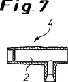
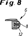
図3〜8においては、見易くするために、この発明によるディスペンサーヘッド1の基本的な構造部分を、改めて個別的に描いている。図3では、この発明にもとづき構成された閉鎖装置1’を有する図1のディスペンサーヘッド1の正面図が描かれている。閉鎖装置1’の無い形のディスペンサーヘッド1を描いた図4と比較することにより、特にディスペンサーヘッド1の大きさに対する閉鎖装置1’の大きさとその大きさがそれに適合していることが、明らかに分かる。図5では、初期位置における閉鎖装置1’全体が、噴射開口部3が閉鎖されるとともに、ドーム6の背面壁12が変形していない形で単独で描かれている。そして、図6〜8では、この閉鎖装置1’の個々の構成部分が、別々に列挙されている。図6は、一方の端部におけるバルブヘッド7と、ドーム6のスリーブ8内に差し込むための他方の先細の端部18とを有するバルブ本体5を図示している。図7は、バルブ本体4を、図8は、背面壁12とその上に配置されたスリーブ8とを有する弾力性のあるドーム6を図示している。
3 to 8, the basic structural parts of the
図9と10には、この発明によるディスペンサーヘッドの第二の実施構成が描かれている。図9は、初期位置におけるディスペンサーヘッド20全体を描いており、図10は、噴射位置におけるディスペンサーヘッド20の断面の部分拡大図を示している。このディスペンサーヘッド20は、一体化した閉鎖装置21を有し、上方部30と下方部31とから構成されている。この閉鎖装置21のバルブケース24内には、バルブ本体スリーブ28が、配置されるとともに、バルブ本体25が、前方から挿入され、ロックされた形で固定されている。バルブ本体25を誘導するために、バルブ本体スリーブ28の前方部は、ノズル本体36とともに、バルブ本体25とバルブ本体スリーブ28間において生成物を噴射させることを可能とするために、誘導領域34に貫流路36’を交互に配置した形で構成されている。この場合、バルブ本体25は、バルブ本体スリーブ28内において、バルブヘッド27が、噴射開口部23を前方から閉鎖する形で配置されている。バルブ本体スリーブ28は、二重壁32を有する噴射流路22の一部として構成され、この噴射流路は、下方の開口部33を通して生成物で満たすことができる。
9 and 10 illustrate a second embodiment of a dispenser head according to the present invention. FIG. 9 depicts the
ディスペンサーヘッド20と閉鎖装置21間の密閉は、二つの弾力性のある環状パッキング32’と32''によって実現されている。これらの二つの環状パッキング32’と32''間には、環状の空間が形成されており、この空間は、生成物を貫流させることが可能であり、従って閉鎖装置21の下方の開口部33をディスペンサーヘッド20の生成物流路19に対して位置決めする必要がなくなる。この措置の効果は、組み立てを容易にすることにある。
The seal between the
この第二のディスペンサーヘッド20の場合、弾力性のある材料を射出成形したバルブ本体スリーブ28の後方端部26が、図1〜8の第一の構成例における弾力性のあるドーム6の復元部品としての機能を果たしており、この後方端部は、弾力性のある環状パッキング32’,32''によってロックされて結合する形でディスペンサーヘッド20の上方部30と下方部31と固定的に結合されている。
In the case of this
噴射プロセスを開始するために、押しボタン37を手で押すことによって閉鎖装置21を傾斜させた場合、バルブ本体スリーブ28は、その復元部品または後方端部26とともに、下方部31の固定ウェブ29に対して円軌道に沿って誘導されて、バルブ本体25と一緒に前方に押し動かされ、そのことによってバルブヘッド27は、噴射開口部23を前方に開放し、バルブヘッド27から矢印の方向39に生成物を噴射する。同時に、弾力性のある後方端部26は、ウェブ29に当たることにより変形する(強く押し付けられる)。噴射プロセスの終了後、バルブ本体スリーブ28の後方端部26は、再びウェブ29から解放されて、強く押し付けられていた後方端部26の復元力と、二重壁32内において依然として圧力下にある生成物によって、この背面壁26’に加えられる圧力とが、バルブ本体スリーブ28をバルブ本体25とともに再び初期位置に押し戻す。この初期位置において、バルブ本体27は、その円錐形に構成された前方部分で、周縁部を後方に張り出す形に形成された噴射開口部23のノズル本体36を点接触により密閉する。
When the closure device 21 is tilted by pushing the push button 37 by hand to start the injection process, the valve body sleeve 28, along with its restoring part or the
図11aと11bには、ノズル本体36とバルブヘッド27を有する噴射開口部閉鎖機構の代替構成が図示されている。図11aには、図9と10と同様の全体構成で、ノズル本体36aが、バルブ本体25aのバルブヘッド27aの円錐体に対応して、同じく円錐体に構成されており、その結果面的に密閉する形の接触が実現されている。図11bでは、バルブヘッド27bとノズル本体36b間を同じく円錐体で密閉するとともにノズル本体36bの誘導領域がより短くされ、更にバルブ本体25bのバルブヘッド27bが、外側に張り出した中心ピン35を持つ形で形成されており、この中心ピン35は、ディスペンサーヘッドから生成物を噴射している間、生成物がより良好に拡散するのを保証するものである。
In FIGS. 11 a and 11 b, an alternative configuration of a jet opening closing mechanism having a
この発明によるディスペンサーヘッドの第三の変化形態が、図12と、断面を拡大した図13に図示されており、図12は初期位置を、図13は噴射位置を示している。このディスペンサーヘッド40は、その中に閉鎖装置41を配置した上方部50と、下方部51とから構成されている。閉鎖装置41は、ノズル本体56を持つバルブケース44とバルブ本体45とから構成され、このバルブヘッド47は、内側からノズル本体56の噴射開口部43を閉鎖している。バルブ本体45の背面壁部分は、バルブヘッド47の方に開いた形の、その反対方向を背面壁52’で密閉された二重壁52で構成されている。この二重壁52は、そうすることによって噴射流路42の一部を構成するとともに、下方の開口部53を通して噴射する生成物で満たすことができる。外側のバルブ本体壁46は、復元部品として、それ以外の壁面部に対して射出成形された形の弾力性のある材料で構成され、弾力性のある環状パッキング46’,46''によってロックされて結合する形で上方部50と下方部51と固定的に結合されている。これらの環状パッキング46’,46''は、図10と同様の方法で、ディスペンサーヘッド40と閉鎖装置41間を密閉する効果を持つとともに、そこで記載したのと同様の方法で、生成物を貫流させる環状の空間を形成することによって、組み立てを容易にするものである。
A third variation of the dispenser head according to the present invention is shown in FIG. 12 and FIG. 13 which is an enlarged cross-section. FIG. 12 shows the initial position and FIG. 13 shows the injection position. The
この初期位置では、弾力性のあるバルブ本体壁46は、復元部品として引張り応力下にあり、バルブ本体45を引っ張って、そのバルブヘッド47でノズル本体56の噴射開口部43を密閉している。この弾力性のあるバルブ本体壁46における引張り応力は、ノズル本体56を、その組み立て時に前方からバルブケース44に挿入して、それによってバルブ本体45を後方に押し動かすことにより実現される。
In this initial position, the resilient
弾力性のあるバルブ本体壁46は、以下の方法により、噴射プロセス時における自動復元部品として機能する。噴射プロセス時に、押しボタン57を操作することによって、噴射する生成物が、下方の開口部53を通って下方から、二重壁52から構成された空洞に流入する。ここで、生成物は、その設定済みの引張り力より大きな圧力により、二重壁52の背面壁52’を押して、その時点では噴射開口部43は、まだ閉じられているので、そのことにより外側の弾力性のあるバルブ本体壁46を延ばすとともに、本来存在する引張り応力に打ち勝って、バルブ本体45を背面壁52’の方向に押し動かす。このように押し動かされることによって、バルブ本体45のバルブヘッド47は、噴射開口部43を内側に開放して、生成物が、ディスペンサーヘッド40から矢印の方向59に噴出することができる。噴射プロセスの終了後に、外側の弾力性のあるバルブ本体壁46の復元力によって、バルブ本体45は、再び自動的にその初期位置に引っ張られて、バルブヘッド47が、噴射開口部43を閉鎖する。この場合、噴射開口部43の閉鎖は、円錐形に先端を鋭くしたバルブヘッド47によって確実に行われ、この先端は、ノズル本体56の噴射開口部43が円錐形に展開するのに適合したものである。
The resilient
図14a〜14cには、前の閉鎖機構の別の実施可能形態が図示されている。図14aでは、バルブヘッド47aの前方部が、円筒形の中心ピン55を持つ形で構成されている。この場合、バルブ本体45aの誘導は、ノズル本体56aの噴射開口部43aに配置された、円筒形のピン55を包み込む円錐形の心出し部を持つ誘導ウェブ58aによって行われる。噴射開口部43aの密閉は、バルブヘッド47aの周りを取り囲む周縁部48をノズル本体56aの背面壁部分と面的に密閉することで実現される。図14bでは、半径方向に対して平坦に構成されたノズル本体56bの背面壁部分とバルブヘッド47bの正面の周りを取り囲む周縁部48間で噴射開口部43aの密閉が行われていること以外は、図14aと同じ構成である。図14cでは、図14aまたは14bと同じ密閉機構による別の変化形態として、バルブ本体45cの誘導部は、更にピン55を誘導するために、バルブ本体45cの延長された前方部45c’をも、それに対応して形成されたノズル本体56c’によって誘導する形で軸支することによって拡張されている。
14a-14c illustrate another possible embodiment of the previous closure mechanism. In FIG. 14 a, the front portion of the
ディスペンサーヘッドの別の(第四の)変化構成が、図15a(初期位置)と15b(ロック位置)に図示されている。上方部70と下方部71とから構成されるディスペンサーヘッド60の閉鎖装置61は、ちょうど図12のディスペンサーヘッド40のように、バルブケース64内に、その後方領域66に復元物体として構成された弾力性のある二重壁72を持つバルブ本体65を有する。バルブヘッド67に向かって開いた形の、その反対側が密閉された二重壁72は、噴射する生成物を下方の開口部73を通して満たすことができるとともに、噴射流路62の一部を構成する。
Another (fourth) variation of the dispenser head is illustrated in FIGS. 15a (initial position) and 15b (locked position). The closing
ディスペンサーヘッド60の初期位置において、バルブ本体65は、その後方の端部72’を、下方部71の固定ウェブ69の前方に張り出したリブ69’に沿って、手で誘導されて、ロックされ、その際バルブヘッド67は、内側から噴射開口部63に押し付けられ、そのことによって同時に弾力性のある形で構成された領域66が強く押し付けられる。この場合、前方に張り出したリブ69’を持つウェブ69は、バルブ本体65が、噴射プロセス時に押しボタン77を手で操作することによる上方部70の円軌道上における傾斜動作によって、このロック状態から回って外れる。後方に解放されたバルブ本体65は、生成物によって二重壁72の背面壁上に加えられた圧力と強く押し付けられた領域66の弾性による跳ね返りとによって、ウェブ69の方向(図面では右に)に引っ張られて、生成物が、矢印の方向79にディスペンサーヘッド60から噴出することができるようになる。
In the initial position of the
次に、噴射プロセスの終了後、バルブヘッド67により噴射開口部63を改めて閉鎖することは、上方部70を戻すように回すことによって行われ、それによってバルブ本体65の後方端部72’が、リブ69’の傾斜した肩部分74に沿って上方に、そして同時に前方に(図面では左に)押し動かされ、そのことによってバルブヘッド67を内側から噴射開口部63に押し付ける。この場合、二重壁72の弾力性のある領域66が、同時に再び強く押し付けられる。この場合、初期位置に回帰するための上方部の復元力は、リブ69’の傾斜した肩部分74に沿ってバルブ本体65の端部72’を引っ張ることを可能とするのに十分な大きさである。図10と図13と同じ方法で、二重壁72の弾力性のある領域66上には、環状パッキング66’,66''が配置されており、これらは、図10と図13に関して記載したのと同じ方法で、ディスペンサーヘッド60と閉鎖装置61間を密閉するとともに、組み立てを容易にする効果を有する。
Next, after the injection process is finished, the injection opening 63 is closed again by the
この発明は、ここに図示したディスペンサーヘッドを持つ記載した実施例だけに限定されるものではなく、この発明にもとづく同じまたは機能的に同じ閉鎖装置は、場合によっては所要の構造の調整を行って、過剰圧力を加えたディスペンサー容器用の別の商用のディスペンサーヘッドに用いることも可能である。 The invention is not limited to the described embodiment with the dispenser head shown here, but the same or functionally the same closure device according to the invention may be adjusted with the necessary construction in some cases. It can also be used in other commercial dispenser heads for dispenser containers that are over-pressured.
1,20,40,60 ディスペンサーヘッド
1’,21,41,61 閉鎖装置
2,22,42,62 噴射流路
3,23,43,43a,63 噴射開口部
4,24,44,64 バルブケース
5,25,25a,25b,45,45a,45b,45c,65 バルブ本体
6,26,46,66 復元部品
7,27,27a,27b,47,47a,47b,47c,67 バルブヘッド
8,28 スリーブ
9,29,69,69’ ウェブ
10,30,50,70 1’,21,41,61の上方部
11,31,51,71 1’,21,41,61の下方部
12 6の背面壁
13 12の有効面積
14 7の有効面積
15 ディスペンサー容器の中心軸
16 2の前端
17,37,57,77 押しボタン
18 5の先細の端部
19 生成物の流路
26’,52’ 26,52の背面壁
32,52,72 25,45,65の二重壁
32’,32'',46’,46'',66’,66'' 26,46,66の環状パッキング
33,53,73 下方の開口部
34 25の誘導領域
35,55 25b,45の中心ピン
36,36a,36b,56,56a,56b,56c ノズル本体
36’ 貫流路
38 ロック結合部
39,59,79 生成物の噴出方向
48 周りを取り囲む周縁部
58a〜58c 誘導ウェブ
74 傾斜した肩部分
1, 20, 40, 60 Dispenser head 1 ', 21, 41, 61 Closing device 2, 22, 42, 62 Injection flow path 3, 23, 43, 43a, 63 Injection opening 4, 24, 44, 64 Valve case 5, 25, 25a, 25b, 45, 45a, 45b, 45c, 65 Valve body 6, 26, 46, 66 Restoring parts 7, 27, 27a, 27b, 47, 47a, 47b, 47c, 67 Valve head 8, 28 Sleeve 9, 29, 69, 69 ′ Upper portion of web 10, 30, 50, 70 1 ′, 21, 41, 61 11, 31, 51, 71 1 ′, lower portion of lower portion 126 of 21, 41, 61 Wall 13 12 Effective area 14 7 Effective area 15 Dispenser container central axis 16 2 Front end 17, 37, 57, 77 Push button 185 Tapered end 19 Product flow path 2 ', 52' 26,52 rear wall 32,52,72 25,45,65 double wall 32 ', 32'',46', 46 '', 66 ', 66''26,46,66 Annular packing 33, 53, 73 Lower opening 34 25 Guide area 35, 55 25b, 45 Central pins 36, 36a, 36b, 56, 56a, 56b, 56c Nozzle body 36 'Through flow path 38 Lock joint 39, 59,79 Product ejection direction 48 Peripheral portions 58a to 58c surrounding the guide web 74 Inclined shoulder portion
Claims (12)
この復元部品(6,26,66)は、閉鎖位置で、噴射開口部(3,23,63)を閉鎖するために弾力的な応力を加えており、前記の噴射開口部(3,23,63)の開閉を自動的に行うとともに、この自動的な開閉が過剰圧力下に有る生成物によって支援されるように構成されていることを特徴とするディスペンサーヘッド(1,20,60)。From de I dispenser container is under excess pressure, bubbles, for example, products, such as shaving foams or gels, product is self-foaming and injection passage for injecting administrable products using other pressure mechanism (2 , 22 , 62), the dispenser head being pluggable into an injection valve of a dispenser container and caused by mechanical pressure applied from the outside to the dispenser head The tilting movement around the center of rotation of the upper part (10 , 30 , 70) of the dispenser head opens the dispense valve of the dispenser container, so that the product is dispensed from the dispense valve by the overpressure. injection passage of (1,20,60) (2,22, 62) flow into To, ejection opening of the dispenser head (3, 23, 63) the dispenser head (1, 20, 60) through the ejected from, the dispenser head (1,20,60) further restoration part (6 , 26, 66) having a closing device (1 ′, 21, 61) with a closing device (3, 23, 63) of the injection flow path (2, 22, 62). ) In the dispenser head that opens and closes again after the end of the injection process ,
This restoring part (6, 26, 66), in the closed position, applies a resilient stress to close the injection opening (3, 23, 63), said injection opening (3, 23, 63) Dispensing head (1 , 20 , 60) , characterized in that it automatically opens and closes 63) and that this automatic opening and closing is assisted by products under excessive pressure .
Applications Claiming Priority (2)
| Application Number | Priority Date | Filing Date | Title |
|---|---|---|---|
| DE20209616U DE20209616U1 (en) | 2002-06-20 | 2002-06-20 | Dispenser head with shut-off valve |
| PCT/EP2003/006373 WO2004000066A1 (en) | 2002-06-20 | 2003-06-17 | Dispenser head with a check valve |
Publications (2)
| Publication Number | Publication Date |
|---|---|
| JP2005529741A JP2005529741A (en) | 2005-10-06 |
| JP4338635B2 true JP4338635B2 (en) | 2009-10-07 |
Family
ID=27675263
Family Applications (1)
| Application Number | Title | Priority Date | Filing Date |
|---|---|---|---|
| JP2004514746A Expired - Fee Related JP4338635B2 (en) | 2002-06-20 | 2003-06-17 | Dispenser head with check valve |
Country Status (9)
| Country | Link |
|---|---|
| US (1) | US7464839B2 (en) |
| EP (1) | EP1513426B1 (en) |
| JP (1) | JP4338635B2 (en) |
| CN (1) | CN100464866C (en) |
| AT (1) | ATE329504T1 (en) |
| DE (2) | DE20209616U1 (en) |
| EA (1) | EA005752B1 (en) |
| ES (1) | ES2264004T3 (en) |
| WO (1) | WO2004000066A1 (en) |
Families Citing this family (31)
| Publication number | Priority date | Publication date | Assignee | Title |
|---|---|---|---|---|
| US20040222246A1 (en) * | 2003-05-05 | 2004-11-11 | The Procter & Gamble Company | Sprayer actuator, sprayer, and method of making the same |
| FR2857343B1 (en) * | 2003-07-08 | 2005-10-07 | Airlessystems | HEAD OF DISTRIBUTION OF FLUID PRODUCT |
| EP1591377A1 (en) * | 2004-04-20 | 2005-11-02 | Lindal Ventil GmbH | Spray cap for an aerosol container |
| FR2869301B1 (en) * | 2004-04-23 | 2007-08-10 | Oreal | HEAD OF DISTRIBUTION WITH REFERMABLE AUTO ORIFICE |
| DE102007049614B4 (en) | 2007-03-15 | 2015-03-05 | Aptar Dortmund Gmbh | dispenser |
| DE102007044180B4 (en) * | 2007-09-15 | 2014-02-06 | Cosmed Gmbh & Co Kg | Self-closing dispensing head for a pressure vessel |
| EP2135822B1 (en) * | 2008-06-20 | 2013-08-21 | Aptar Dortmund GmbH | Dispensing device |
| DE102008038654B4 (en) | 2008-08-12 | 2019-09-19 | Aptar Dortmund Gmbh | Dispensing head with swiveling valve element |
| KR101025191B1 (en) * | 2009-03-03 | 2011-04-01 | (주)톨리코리아 | Apparatus for opening and shutting nozzle of cosmetic case |
| DE102009030627B4 (en) | 2009-06-25 | 2020-03-12 | Aptar Dortmund Gmbh | Valve and dispenser |
| US8444019B2 (en) | 2009-08-07 | 2013-05-21 | Ecolab Usa Inc. | Wipe and seal product pump |
| TWM390180U (en) * | 2009-12-04 | 2010-10-11 | Taiwan Bor Ying Corp | Cover nozzle for a high pressure gas tank |
| WO2012100014A1 (en) | 2011-01-21 | 2012-07-26 | The Gillette Company | Actuator for a dispensing apparatus |
| JP5612220B2 (en) | 2011-01-21 | 2014-10-22 | ザ ジレット カンパニー | Actuator for dispensing equipment |
| US8701945B2 (en) * | 2011-02-25 | 2014-04-22 | Dow Global Technologies Llc | Compressed fluid dispensing device with internal seal |
| US9120109B2 (en) | 2012-02-29 | 2015-09-01 | Universidad De Sevilla | Nozzle insert device and methods for dispensing head atomizer |
| US8881956B2 (en) | 2012-02-29 | 2014-11-11 | Universidad De Sevilla | Dispensing device and methods for emitting atomized spray |
| US8800824B2 (en) | 2012-02-29 | 2014-08-12 | Alfonso M. Gañan-Calvo | Sequential delivery valve apparatus and methods |
| CA2883370A1 (en) | 2012-08-31 | 2014-03-06 | Arminak & Associates, Llc | Inverted squeeze foamer |
| DE102013113791A1 (en) * | 2013-12-10 | 2015-06-11 | Rpc Bramlage Gmbh | donor |
| JP6214471B2 (en) * | 2014-05-29 | 2017-10-18 | 株式会社吉野工業所 | Dispenser |
| US20150360245A1 (en) * | 2014-06-12 | 2015-12-17 | Derjin (Hong Kong) Holding Company Limited | Spray head assembly |
| DE102016221820A1 (en) * | 2016-11-08 | 2018-05-09 | Beiersdorf Ag | Self-closing dispensing head |
| CN106890742A (en) * | 2017-04-17 | 2017-06-27 | 浙江金马实业有限公司 | A kind of controlled valve structure for emulsion pumps |
| EP3489171A1 (en) | 2017-11-23 | 2019-05-29 | The Procter & Gamble Company | Piston with flexible closure for aerosol container |
| EP3513880B1 (en) * | 2018-01-23 | 2021-08-25 | The Procter & Gamble Company | Dispensing device suitable for a foamable product |
| US10850914B2 (en) | 2018-11-08 | 2020-12-01 | The Procter And Gamble Company | Dip tube aerosol dispenser with upright actuator |
| US11267644B2 (en) | 2018-11-08 | 2022-03-08 | The Procter And Gamble Company | Aerosol foam dispenser and methods for delivering a textured foam product |
| US11253111B2 (en) | 2019-08-22 | 2022-02-22 | Gpcp Ip Holdings Llc | Skin care product dispensers and associated self-foaming compositions |
| US11440726B1 (en) * | 2021-03-26 | 2022-09-13 | Silgan Dispensing Systems Corporation | Aerosol sprayers and methods of using the same |
| EP4353624A1 (en) | 2021-06-07 | 2024-04-17 | Eric Zembrod | Retention valve for a range of packaging |
Family Cites Families (17)
| Publication number | Priority date | Publication date | Assignee | Title |
|---|---|---|---|---|
| CA1166203A (en) * | 1979-12-21 | 1984-04-24 | Luigi Del Bon | Self-sealing actuating device for mounting on a discharge valve of a pressurized container |
| FR2594808B1 (en) | 1986-02-21 | 1988-12-30 | Oreal | DEVICE FOR OPERATING A VALVE MOUNTED ON A PRESSURIZED CONTAINER |
| CN1032319A (en) * | 1987-09-29 | 1989-04-12 | 喷雾科技企业公司 | The dispenser head that product semiliquid, viscous or pasty state is used |
| EP0449774B1 (en) * | 1990-03-24 | 1993-11-03 | George Edgar Callahan | Dispenser for foaming a liquid product |
| CH680359A5 (en) * | 1991-08-28 | 1992-08-14 | Supermatic Kunststoff Ag | |
| FR2684080B1 (en) * | 1991-11-27 | 1994-01-28 | Oreal | DEVICE FOR CONTROLLING THE DISTRIBUTION OF A CIRCUIT, IN PARTICULAR A SELF-PUSHING PRODUCT. |
| DE4231940A1 (en) | 1992-09-24 | 1994-03-31 | Inter Airspray Sweden Ab Trell | Foam spraying device |
| NL9300517A (en) | 1993-03-23 | 1994-10-17 | Airspray Int Bv | Foam forming assembly, a suitable spray head and a spray can comprising such an assembly. |
| FR2716873B1 (en) * | 1994-03-03 | 1996-04-19 | Frank Clanet | Sealing device for sealing the contents of a pressurized container or a pump container. |
| US5732855A (en) * | 1995-03-06 | 1998-03-31 | Park Towers International B.V. | Spray head intended for a spray can, and spray can provided with such a spray head |
| GB2312478B (en) | 1996-04-23 | 1999-09-15 | Soft 99 Corp | Spray control nozzle for aerosol container |
| US5829640A (en) * | 1996-09-06 | 1998-11-03 | The Procter & Gamble Company | Dispensing pump |
| GB9702688D0 (en) * | 1997-02-10 | 1997-04-02 | Bespak Plc | A dispensing apparatus |
| DE19742420A1 (en) | 1997-09-25 | 1999-04-01 | Anton Jaeger | Rotor jet head for cleaning device |
| FR2775262B1 (en) * | 1998-02-25 | 2000-05-12 | Oreal | DISTRIBUTION HEAD FOR THE DISTRIBUTION OF A PRODUCT AND PRESSURE DISTRIBUTION ASSEMBLY EQUIPPED WITH THIS HEAD |
| DE29818005U1 (en) * | 1998-10-08 | 1998-12-24 | Georg Menshen Gmbh & Co Kg | Self-closing container closure |
| US6116472A (en) * | 1998-12-15 | 2000-09-12 | Calmar Inc. | Trigger acutated pump sprayer |
-
2002
- 2002-06-20 DE DE20209616U patent/DE20209616U1/en not_active Expired - Lifetime
-
2003
- 2003-06-17 EP EP03760629A patent/EP1513426B1/en not_active Revoked
- 2003-06-17 JP JP2004514746A patent/JP4338635B2/en not_active Expired - Fee Related
- 2003-06-17 WO PCT/EP2003/006373 patent/WO2004000066A1/en active IP Right Grant
- 2003-06-17 DE DE50303849T patent/DE50303849D1/en not_active Revoked
- 2003-06-17 CN CNB038143143A patent/CN100464866C/en not_active Expired - Fee Related
- 2003-06-17 AT AT03760629T patent/ATE329504T1/en not_active IP Right Cessation
- 2003-06-17 US US10/509,864 patent/US7464839B2/en not_active Expired - Fee Related
- 2003-06-17 ES ES03760629T patent/ES2264004T3/en not_active Expired - Lifetime
- 2003-06-17 EA EA200401320A patent/EA005752B1/en not_active IP Right Cessation
Also Published As
| Publication number | Publication date |
|---|---|
| ES2264004T3 (en) | 2006-12-16 |
| EA005752B1 (en) | 2005-06-30 |
| DE50303849D1 (en) | 2006-07-27 |
| EA200401320A1 (en) | 2005-02-24 |
| EP1513426A1 (en) | 2005-03-16 |
| WO2004000066A1 (en) | 2003-12-31 |
| US7464839B2 (en) | 2008-12-16 |
| EP1513426B1 (en) | 2006-06-14 |
| DE20209616U1 (en) | 2003-07-31 |
| CN1662163A (en) | 2005-08-31 |
| JP2005529741A (en) | 2005-10-06 |
| CN100464866C (en) | 2009-03-04 |
| ATE329504T1 (en) | 2006-07-15 |
| US20050103811A1 (en) | 2005-05-19 |
Similar Documents
| Publication | Publication Date | Title |
|---|---|---|
| JP4338635B2 (en) | Dispenser head with check valve | |
| JP4355780B2 (en) | Trigger type pump dispenser | |
| JP2006517861A (en) | Nozzle device | |
| US20080251543A1 (en) | Cap for an Aerosol Container or a Spray Container | |
| JP2004307071A (en) | Unit for storing product including cosmetics and dispensing them under pressure | |
| US20080017670A1 (en) | Pump Dispenser | |
| JPH09222075A (en) | Discharge device for fluid substance | |
| US2975944A (en) | Foam valve assembly | |
| EP3513880B1 (en) | Dispensing device suitable for a foamable product | |
| JP2008036488A (en) | Trigger type pump dispenser | |
| WO2013140173A2 (en) | Nozzle | |
| JP2589452Y2 (en) | Liquid injection device | |
| WO2007042794A2 (en) | Pump dispenser and method of manufacturing a pump dispenser | |
| JP2002166982A (en) | Aerosol spray apparatus | |
| KR20120060043A (en) | Dispenser Pump Button | |
| JP2005536346A (en) | Discharge device for container or vessel | |
| JP3695040B2 (en) | Double structure container | |
| JPH1111554A (en) | Aerosol device for injecting mixed solution | |
| JP3250069B2 (en) | Aerosol container | |
| JPH084467Y2 (en) | Metering valve for aerosol containers | |
| JP6531004B2 (en) | Dispenser | |
| JP6401031B2 (en) | Aerosol container press head | |
| JPH08133360A (en) | Inclined actuation type spray head structure | |
| KR102600967B1 (en) | Dispensing closure having automatic sealing valve | |
| US3416711A (en) | Self-purging pressure dispenser valve |
Legal Events
| Date | Code | Title | Description |
|---|---|---|---|
| A621 | Written request for application examination |
Free format text: JAPANESE INTERMEDIATE CODE: A621 Effective date: 20060125 |
|
| A131 | Notification of reasons for refusal |
Free format text: JAPANESE INTERMEDIATE CODE: A131 Effective date: 20090106 |
|
| A521 | Request for written amendment filed |
Free format text: JAPANESE INTERMEDIATE CODE: A523 Effective date: 20090310 |
|
| TRDD | Decision of grant or rejection written | ||
| A01 | Written decision to grant a patent or to grant a registration (utility model) |
Free format text: JAPANESE INTERMEDIATE CODE: A01 Effective date: 20090623 |
|
| A01 | Written decision to grant a patent or to grant a registration (utility model) |
Free format text: JAPANESE INTERMEDIATE CODE: A01 |
|
| A61 | First payment of annual fees (during grant procedure) |
Free format text: JAPANESE INTERMEDIATE CODE: A61 Effective date: 20090630 |
|
| R150 | Certificate of patent or registration of utility model |
Free format text: JAPANESE INTERMEDIATE CODE: R150 |
|
| FPAY | Renewal fee payment (event date is renewal date of database) |
Free format text: PAYMENT UNTIL: 20120710 Year of fee payment: 3 |
|
| FPAY | Renewal fee payment (event date is renewal date of database) |
Free format text: PAYMENT UNTIL: 20120710 Year of fee payment: 3 |
|
| FPAY | Renewal fee payment (event date is renewal date of database) |
Free format text: PAYMENT UNTIL: 20130710 Year of fee payment: 4 |
|
| LAPS | Cancellation because of no payment of annual fees |