JP4331982B2 - Steel strip cooling device - Google Patents
Steel strip cooling device Download PDFInfo
- Publication number
- JP4331982B2 JP4331982B2 JP2003172695A JP2003172695A JP4331982B2 JP 4331982 B2 JP4331982 B2 JP 4331982B2 JP 2003172695 A JP2003172695 A JP 2003172695A JP 2003172695 A JP2003172695 A JP 2003172695A JP 4331982 B2 JP4331982 B2 JP 4331982B2
- Authority
- JP
- Japan
- Prior art keywords
- nozzle
- cooling
- steel strip
- cooling device
- gas
- Prior art date
- Legal status (The legal status is an assumption and is not a legal conclusion. Google has not performed a legal analysis and makes no representation as to the accuracy of the status listed.)
- Expired - Fee Related
Links
Images


Classifications
-
- C—CHEMISTRY; METALLURGY
- C21—METALLURGY OF IRON
- C21D—MODIFYING THE PHYSICAL STRUCTURE OF FERROUS METALS; GENERAL DEVICES FOR HEAT TREATMENT OF FERROUS OR NON-FERROUS METALS OR ALLOYS; MAKING METAL MALLEABLE, e.g. BY DECARBURISATION OR TEMPERING
- C21D9/00—Heat treatment, e.g. annealing, hardening, quenching or tempering, adapted for particular articles; Furnaces therefor
- C21D9/52—Heat treatment, e.g. annealing, hardening, quenching or tempering, adapted for particular articles; Furnaces therefor for wires; for strips ; for rods of unlimited length
- C21D9/54—Furnaces for treating strips or wire
- C21D9/56—Continuous furnaces for strip or wire
- C21D9/573—Continuous furnaces for strip or wire with cooling
-
- C—CHEMISTRY; METALLURGY
- C21—METALLURGY OF IRON
- C21D—MODIFYING THE PHYSICAL STRUCTURE OF FERROUS METALS; GENERAL DEVICES FOR HEAT TREATMENT OF FERROUS OR NON-FERROUS METALS OR ALLOYS; MAKING METAL MALLEABLE, e.g. BY DECARBURISATION OR TEMPERING
- C21D1/00—General methods or devices for heat treatment, e.g. annealing, hardening, quenching or tempering
- C21D1/56—General methods or devices for heat treatment, e.g. annealing, hardening, quenching or tempering characterised by the quenching agents
- C21D1/613—Gases; Liquefied or solidified normally gaseous material
-
- C—CHEMISTRY; METALLURGY
- C21—METALLURGY OF IRON
- C21D—MODIFYING THE PHYSICAL STRUCTURE OF FERROUS METALS; GENERAL DEVICES FOR HEAT TREATMENT OF FERROUS OR NON-FERROUS METALS OR ALLOYS; MAKING METAL MALLEABLE, e.g. BY DECARBURISATION OR TEMPERING
- C21D1/00—General methods or devices for heat treatment, e.g. annealing, hardening, quenching or tempering
- C21D1/62—Quenching devices
- C21D1/667—Quenching devices for spray quenching
Description
【0001】
【発明の属する技術分野】
本発明は、例えば、鋼帯の連続焼鈍設備、連続式溶融亜鉛めっき設備、カラーコーティングラインおよびステンレス酸洗焼鈍ライン等において、連続して走行する鋼帯を冷却する装置に関するものである。
【0002】
【従来の技術】
連続焼鈍炉設備は良く知られているように、鋼帯を連続的に加熱・均熱および冷却し、必要により過時効処理する工程を備えている。ところで、鋼帯の特性を所望のものにするためには、加熱温度や均熱時間のほかに、その鋼帯を均一急速冷却することが重要である。鋼帯の冷却方法として、現状各種の冷却媒体が採用されており、この冷媒の選択によって鋼帯の冷却速度も異なってくる。
【0003】
このうち、水を冷媒として用いる場合、かなり高い冷却速度が得られ超急冷域までの冷却が司能であるが、焼き入れ歪によってクーリングバックルといわれる鋼帯の形状変化が発生することが最大の難点である。また、水との接触により鋼帯の表面に酸化膜が生じ、これを除去するための設備が別に必要となり、経済的に有利な設備とはいえない。
【0004】
この問題を解決するため、ロールの内部に水またはその他の冷却媒体を通し、この冷却されたロール表面に鋼帯を接触させて冷却するロール冷却方法がある。この方法は次のような問題がある。すなわち、連続焼鈍炉を通過する鋼帯はすべて平坦度を保っているとは限らない。従って、冷却ロールに接する際に、局部的に非接触となる場合があり、この非接触により鋼帯の幅方向の冷却が不均一となり、鋼帯の形状が変形する原因となる。そのため、冷却ロールヘの接触前に鋼帯の平坦化を行う手段が必要となり、これが設備費をアップさせていた。
【0005】
別の冷却手段としてガスを冷媒とする冷却方法が実用化され、多くの実績を上げている。この方法は、前記した水冷却やロール冷却に比べて冷却速度が遅いが、比較的鋼帯の幅方向の均一な冷却が可能である。このガス冷却の最大の難点である、冷却速度を上げるため、ガスを噴射するノズルの先端を鋼帯に極力近づけて熱伝達率を上げて冷却速度を上げるものや、冷却媒体として水素ガスの濃度を上げて熱伝達率を上げたものを採用したものが開示されている。
【0006】
噴射するノズルの先端を鋼帯に近接させて熱伝達率を上げるものとして、特許文献1がある。この技術は、ノズルの先端と鋼帯との距離を小さくして効率よい冷却を可能にしたものである。具体的には、冷却ガス室に設けられた冷却ガス室表面から突出する突出ノズルの長さを100mm−Z以上とし、突出ノズルから噴射されたガスが鋼帯に当たって背部に逃げる部分が設けられている。これにより、噴射されたガスが鋼帯表面に滞留することを減少し、鋼帯の幅方向における冷却均一性を向上させることが開示されている。なお、Zは突出ノズル先端と鋼帯との距離を示す。
【0007】
【特許文献1】
特公平2−16375号公報
【0008】
また、ノズルの突出高さを50mm−Zから200mm−Zまで種々変えて熱伝達係数の最適点を導き出す実験を行っている。そして、連続焼鈍炉の冷却帯に用いられる冷却装置として、この実験から効率的冷却能力を持つ冷却装置を提案している。この冷却装置により、通常100kcal/m2 h℃であった熱伝達係数が400kca1/m2 h℃まで上げることが出来るようになった。
【0009】
しかし、さらなる冷却速度の向上が望まれるようになり、通常の冷却媒体としてN2 :95%程度+H2 :5%程度の雰囲気ガスを循環させる既存の冷却装置では限界があった。
この問題を解決するため、冷却媒体として水素ガスを使用することが考えられた。水素ガスを採用することにより冷却能力が向上することは、古くから知られていたが、水素ガスの危険性から実機への適用はされていなかった。
【0010】
この水素ガス濃度を上げて急速冷却する技術が特許文献2に開示されている。この技術は急速冷却帯において、冷却ガスの水素濃度を30%〜60%、その吹き付け速度を100m/秒〜150m/秒として鋼帯に吹き付ける冷却速度である。このように、水素ガスを採用するための具体的技術が開発され、実機化されようとしている。
【0011】
【特許文献2】
特開平9−235626号公報
【0012】
【発明が解決しようとする課題】
通常、N2 ガス主体の雰囲気ガスによる冷却からH2 濃度を上げて、かつ、ノズルからの吐出流速を100m/秒〜150m/秒必要なため、鋼帯に吹き付けられるガスの量も多量のガスが必要となる。また、100m/秒〜150m/秒をノズルから噴出させるための圧力も必要となる。一般にこれらの冷却装置は、鋼帯の吹きつけた冷却媒体をダクトを介して循環させ、再度吹き付ける循環式冷却装置を採用している。この循環式冷却装置では、鋼帯に吹き付けた冷却媒体が炉内に排出され、炉体に設けた吸い込みダクトとから循環ブロワによって吸引される。循環ブロワの前には、鋼帯に吹き付けて温度上昇した冷却媒体を吹き付け温度に冷却する熱交換機が設置されており、これらの装置により循環を行いながら鋼帯を冷却するようになっている。
【0013】
これら循環装置での必要圧力はノズルからの噴出する際に必要な圧力が一番高く、このノズル部の圧損を極力低くすることが望まれていた。
【0014】
【課題を解決するための手段】
上記課題を解決するため、本発明の要旨は以下の構成からなる。
(1)冷却箱の表面に、ノズルの先端から鋼帯面までの距離を50〜100mmに保持する複数のノズルを突出させ、このノズルから冷媒を噴出させて走行する鋼帯を冷却する鋼帯の冷却装置において、前記ノズルの全長を200mmとし、ノズル基部内径Dとノズル先端内径dを1.5≦D/d≦3.0となる円錐形状のノズルを配設したことを特徴とする鋼帯の冷却装置。
【0016】
(2)前記冷却箱に設けるノズル取付け用孔径は、[ノズル全長L−10mm(ノズル基部から先端側に10mmの位置)±3mm]の範囲のところを孔径とし、前記孔径に前記ノズルの基部を拡管接合により固定してなることを特徴とする前記(1)に記載の鋼帯の冷却装置。
【0018】
(3)冷媒として、N2 およびH2 その他の不活性ガスからなる混合ガスとし、H2 濃度を5〜60%、残りをNまたはその他の不活性ガスとしたことを特徴とする前記(1)に記載の鋼帯の冷却装置。
【0019】
【発明の実施の態様】
以下に本発明を図に示す実施例に基づいて詳細に説明する。
図1は本発明を適用した連続焼鈍設備の冷却装置の側部断面図、図2は図1のA−A矢視図、図3は本発明のノズルの詳細図、図4は本発明のノズルの取り付け要領を示す図、図5はノズルの抵抗係数を示すグラフ、図6は連続式塗装ラインに本発明の冷却装置を適用した概略図、図7、図8は連続溶融亜鉛めっき設備のめっき後を鋼帯を冷却する冷却装置に本発明例を適用した概略図である。
【0020】
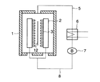
図1において、鋼帯12を搬送する上下ロール9,11間に設置され、このロール間に、ガスを噴出する冷却装置2の一対を鋼帯12の面に対向して設け、この冷却装置2を鋼帯12の流れに沿って複数段配置している。そしてこの冷却装置2の上下間には鋼帯のバタツキを防止する押さえロール10を鋼帯12を挟持するように配置している。
【0021】
図2は、図1のA−A矢視図であり、冷却装置2により鋼帯12に吹き付けられたガスは循環系を介して冷却ガスとして再利用される。すなわち、吹き付けられたガスは、炉体1に設けられたガス吸い込み口から吸い込まれ、吸引側ダクト5、熱交換機6、循環ブロワ7および吐出側ダクト8を介し、さらに、炉体内の冷却箱3に連結された循環系により、冷却箱3の鋼帯12面側に設けられたノズルから鋼帯12に向けて再び噴出される。このように、鋼帯12に吹き付けられた炉内のガスを循環して使用する。
【0022】
冷却装置2は、冷却箱3とこの冷却箱3の鋼帯12面側に設けた突出ノズル4からなっている。この突出ノズル4は基部B側ノズル内径Dと先端A側ノズル内径dの比(D/d)が1.5〜3.0となるようなノズルを選定し、配置している。また、先端ノズルの開口面積が冷却箱表面積の2〜4%となるように配置している。
【0023】
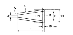
図3には、本発明のノズル形状を示し、Dはノズル基部B側の内径(ここで、ノズル基部B側とは冷却箱3に取付け側をいう)、D0 はノズル基部B側の外径で、dはノズル先端A側の内径、Lはノズルの全長、DNはノズル基部Bを起点として、(ノズル全長L)−(10mm±3mm)の範囲、言い換えると、ノズル基部B側より先端B側10mm±3mmの範囲におけるノズルの外径を指している。ノズル4は円錐形状となるため、SUS(ステンレス鋼)のプレートを板巻きして製作した。ノズルは板巻きのほか、引き抜き鋼管や削り出し、また、鋳造で製作することも可能である。ノズル全長Lは200mmとしてD/dが種々のものを製作して実験を行った。
【0024】
図4には、本発明のノズルを冷却箱3に取り付けるときの状況を示し、冷却箱3の鋼帯12方向の面にDN径の孔を設ける。孔の数は開口面積が冷却箱表面積の2〜4%なるように設けている。DN径は、図3に示すノズル基部Bから先端部A側へ10mm±3mmの範囲におけるノズル径とした。
【0025】
詳述すると、まず、冷却箱3の表面にDN径の孔を開ける。この孔に基部Bの外径D0 ノズルを差込み、ポンチ(図示せず)にて図4に示すように冷却箱3に打ち込む。ノズル4を打ち込む際、図4のようにノズルの基部Bが冷却箱の内面に突出しないように打ち込む。図4ではノズル基部Bが冷却箱3にその面内よりa:10mmを残して装入されるように打ち込んでいる。そして、打ち込まれたノズル4の基部B側より拡管器により基部側ノズル内径Dを拡管し、冷却箱3に設けた孔DN径に圧着する。拡管機により圧着することで、従来、溶接で取り付けていた場合よりもノズル4の取り付け精度は向上する。
なお、DN径の位置を上記のように限定したのは、上限以上(10mm+3mmを超える)とすると、冷却箱への挿入が困難となり、また下限より少ないと密着性が劣ることになる。
図4ではノズルの抵抗係数を減じるために冷却箱3の内表面からノズルの基部側の先端を埋設したが、抵抗係数を減じるものであれば、冷却箱3の内表面に合わせることも可能である。
【0026】
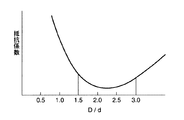
このように、製作したノズルを実験装置により圧力損失を求め、それぞれの抵抗係数を算出した。その結果を図5に示す。D/d=1.0、すなわち、従来のストレートノズルに比べD/d=1.5〜3.0のときが抵抗係数が小さく、2.0近傍が最も小さいことが判明した。このように、従来のストレートノズルに比ベノズルの抵抗係数が30%程度小さくなる。
【0027】
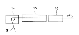
図6に連続式塗装ラインの塗装および乾燥・焼付け炉の配置を示す。鋼帯S1は、コーター設備14にて表面に塗装をコーティングされ、乾燥・焼付け炉15において所定の温度パターンに沿って乾燥・焼付けされる。引き続いて冷却装置16で常温近くまで冷却される。従来、この冷却装置16は前段を空冷、後段を水冷することによって、冷却前段での塗料表面品質確保と後段での急速冷却を実現していた。冷却設備16に本発明によるノズルを用いた冷却設備とすることで、水冷を用いることなく冷却効率のよい設備構成とすることができる。
【0028】
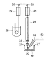
図7は、連続式溶融亜鉛めっき設備のメッキ合金化処理後の冷却設備に本発明によるノズルを用いた冷却設備を適用する例を示す。鋼帯S2 はターンダウンセクション17内に設けられたターンダウンロール18を経てメッキポット19に導入される。シンクロール20を介して垂直に引き上げられ、メッキ機21にて所定のメッキ厚みに調整された後、合金化加熱装置22で合金化処理温度に加熱され、引き続き保持炉23で保熱される。合金化を完了した鋼帯S2 は冷却装置24及びダウンパスに設けられた冷却装置27にて冷却され、最終冷却である浸漬冷却装置28へ送られる。本発明よるノズルを用いた冷却設備を冷却装置24及び冷却装置27へ適用することで、冷却効率を高め合金化炉全体を低層化することが可能となり、また、合金化処理後の鋼帯S2 を急速冷却することで合金層の健全化を計ることが可能となる。
【0029】
図8は、同じく連続式溶融亜鉛めっき設備のメッキ後の冷却設備に本発明によるノズルを用いた冷却設備を適用する例を示す。鋼帯S2 は、メッキ機21にて所定のメッキ厚みに調整された後、冷却装置24及びダウンパスに設けられた冷却装置27にて冷却され、最終冷却である浸漬冷却装置28へ送られる。本発明よるノズルを用いた冷却設備を冷却装置24及び27へ適用することで、冷却効率を高め合金化炉全体を低層化することが可能となる。
【0030】
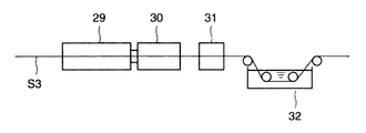
図9は、ステンレス鋼帯の連続焼鈍酸洗設備の一例を示す。ステンレス鋼帯S3 は、加熱帯29において所定の焼鈍温度に加熱・均熱された後、冷却帯30において所定冷却速度で終点温度まで冷却される。引き続いて脱スケール装置31にてステンレス鋼帯S3 の上下面に配設したロール群によってステンレス鋼帯表面に生成したスケールが除去される。その後、酸洗槽32に導入される。冷却設備30に本発明によるノズルを用いた冷却設備を適用することで、冷却効率を高めコンパクトな装置構成とすることができる。
【0031】
【発明の効果】
このように、高冷却速度を得るため、益々、ノズルからの噴出速度を速くし、ノズルの抵抗係数を小さくして、循環設備をコンパクトにすることが最重要課題であり、これに対する本発明の効果は非常に大きい。また、従来の溶接構造から拡管機による圧着構造としたため、溶接によるノズルの歪も解消し、製作精度が向上する。
【図面の簡単な説明】
【図1】本発明を適用した連続焼鈍設備の冷却装置の側部断面図。
【図2】図1のA−A矢視図。
【図3】本発明のノズルの詳細図。
【図4】本発明のノズルの取り付け要領を示す図。
【図5】ノズルの抵抗係数を示すグラフ。
【図6】 本発明を適用した連続式塗装ラインの概略図。
【図7】本発明を適用した連続式溶融亜鉛メッキ設備の概略図。
【図8】本発明を適用した別の連続式溶融亜鉛メッキ設備の概略図。
【図9】本発明を適用したステンレス連続式焼鈍酸洗設備の概略図。
【符号の説明】
1:冷却帯
2:冷却装置
3:冷却箱
4:ノズル
5:吸引側ダクト
6:熱交換機
7:循環ブロワ
8:吐出側ダクト
9:トップロール
10:押さえロール
11:ボトムロール
12:鋼帯
13:仕切り壁
14:コーター設備
15:乾燥・焼付け炉
16:冷却装置
17:ターンダウンセクション
18:ターンダウンロール
19:メッキポット
20:シンクロール
21:メッキ槽
22:加熱装置
23:保熱炉
24:冷却装置
25:トップロール
26:トップロール
27:冷却装置
28:浸漬冷却装置
29:加熱帯
30:冷却帯
31:脱スケール装置
32:酸洗槽
A:ノズル先端
B:ノズル基端[0001]
BACKGROUND OF THE INVENTION
The present invention relates to an apparatus for cooling a continuously running steel strip in, for example, a continuous annealing equipment for a steel strip, a continuous hot dip galvanizing equipment, a color coating line, a stainless acid pickling annealing line, and the like.
[0002]
[Prior art]
As is well known, continuous annealing furnace equipment includes a process of continuously heating, soaking, and cooling a steel strip and, if necessary, overaging. By the way, in order to obtain the desired properties of the steel strip, it is important to uniformly and rapidly cool the steel strip in addition to the heating temperature and the soaking time. Various cooling media are currently used as a method for cooling the steel strip, and the cooling speed of the steel strip varies depending on the selection of the refrigerant.
[0003]
Of these, when water is used as the refrigerant, a fairly high cooling rate is obtained and cooling to the ultra-quenching region is the competence, but it is the biggest that the steel strip shape change called cooling buckle occurs due to quenching strain It is a difficulty. In addition, an oxide film is formed on the surface of the steel strip due to contact with water, and a separate facility is required to remove it, which is not economically advantageous.
[0004]
In order to solve this problem, there is a roll cooling method in which water or other cooling medium is passed through the inside of the roll, and a steel strip is brought into contact with the cooled roll surface for cooling. This method has the following problems. That is, not all the steel strips passing through the continuous annealing furnace maintain flatness. Therefore, when contacting the cooling roll, there is a case where it is locally not in contact, and this non-contact causes cooling in the width direction of the steel strip, which causes deformation of the steel strip. Therefore, a means for flattening the steel strip is required before contact with the cooling roll, which increases the equipment cost.
[0005]
As another cooling means, a cooling method using a gas as a refrigerant has been put into practical use and has achieved many achievements. This method has a slower cooling rate than the above-described water cooling and roll cooling, but relatively uniform cooling in the width direction of the steel strip is possible. In order to increase the cooling rate, which is the biggest difficulty of this gas cooling, the tip of the nozzle that injects the gas is brought close to the steel strip as much as possible to increase the heat transfer rate, and the concentration of hydrogen gas as the cooling medium. The thing which employ | adopted what raised the heat transfer rate by raising is disclosed.
[0006]
There exists
[0007]
[Patent Document 1]
Japanese Patent Publication No. 2-16375 [0008]
Also, experiments are conducted to derive the optimum point of the heat transfer coefficient by changing the protrusion height of the nozzle from 50 mm-Z to 200 mm-Z. As a cooling device used in the cooling zone of the continuous annealing furnace, a cooling device having an efficient cooling capacity is proposed from this experiment. The cooling device, the heat transfer coefficient was usually 100kcal / m 2 h ℃ has become possible to raise up 400kca1 / m 2 h ℃.
[0009]
However, further improvement in the cooling rate has been desired, and there is a limit to existing cooling devices that circulate atmospheric gas of about N 2 : 95% + H 2 : 5% as a normal cooling medium.
In order to solve this problem, it has been considered to use hydrogen gas as a cooling medium. Although it has been known for a long time that the cooling capacity is improved by using hydrogen gas, it has not been applied to actual machines due to the danger of hydrogen gas.
[0010]
[0011]
[Patent Document 2]
Japanese Patent Laid-Open No. 9-235626
[Problems to be solved by the invention]
Usually N 2 H 2 from cooling by gas atmosphere Since the concentration is increased and the discharge flow rate from the nozzle is required to be 100 m / sec to 150 m / sec, a large amount of gas is required to be blown onto the steel strip. Moreover, the pressure for injecting 100 m / sec-150 m / sec from a nozzle is also needed. Generally, these cooling devices employ a circulating cooling device in which a cooling medium sprayed with a steel strip is circulated through a duct and sprayed again. In this circulation type cooling device, the cooling medium sprayed on the steel strip is discharged into the furnace and sucked by the circulation blower from the suction duct provided in the furnace body. In front of the circulation blower, a heat exchanger that cools the cooling medium, which has been sprayed onto the steel strip and has risen in temperature, to the spray temperature is installed, and the steel strip is cooled while being circulated by these devices.
[0013]
The required pressure in these circulation devices is the highest required for ejection from the nozzle, and it has been desired to reduce the pressure loss of the nozzle as much as possible.
[0014]
[Means for Solving the Problems]
In order to solve the above problems, the gist of the present invention comprises the following configurations.
(1) A steel strip that projects a plurality of nozzles that maintain the distance from the tip of the nozzle to the steel strip surface at 50 to 100 mm on the surface of the cooling box, and cools the steel strip that travels by jetting refrigerant from the nozzle. in the cooling system, steel, characterized in that the total length of the nozzle and 200 mm, were provided with a nozzle conical comprising a nozzle base inside diameter D and the nozzle tip inner diameter d and 1.5 ≦ D / d ≦ 3.0 Belt cooling system.
[0016]
( 2 ) The nozzle mounting hole diameter provided in the cooling box has a hole diameter in a range of [nozzle total length L-10 mm (position of 10 mm from the nozzle base to the front end side) ± 3 mm], and the nozzle diameter is the base of the nozzle. Is fixed by pipe expansion joining, and the steel strip cooling device according to (1) above.
[0018]
( 3 ) As a refrigerant, N 2 And H 2 A mixed gas composed of other inert gas and H 2 The steel strip cooling device according to (1) above, wherein the concentration is 5 to 60 % and the remainder is N or other inert gas.
[0019]
BEST MODE FOR CARRYING OUT THE INVENTION
Hereinafter, the present invention will be described in detail based on embodiments shown in the drawings.
FIG. 1 is a side sectional view of a cooling device for a continuous annealing equipment to which the present invention is applied, FIG. 2 is a view taken along arrow AA in FIG. 1, FIG. 3 is a detailed view of a nozzle of the present invention, and FIG. FIG. 5 is a graph showing the nozzle installation procedure, FIG. 5 is a graph showing the resistance coefficient of the nozzle, FIG. 6 is a schematic diagram in which the cooling device of the present invention is applied to a continuous coating line, and FIGS. It is the schematic which applied the example of this invention to the cooling device which cools a steel strip after plating.
[0020]
In FIG. 1, a pair of
[0021]
FIG. 2 is an AA arrow view of FIG. 1, and the gas blown to the
[0022]
The
[0023]
FIG. 3 shows the nozzle shape of the present invention, where D is the inner diameter on the nozzle base B side (where the nozzle base B side is the side attached to the cooling box 3), and D0 is the outer diameter on the nozzle base B side. Where d is the inner diameter of the nozzle tip A side, L is the total length of the nozzle, DN is the range of (nozzle total length L) − (10 mm ± 3 mm) starting from the nozzle base B, in other words, the tip B from the nozzle base B side. It refers to the outer diameter of the nozzle in the range of 10 mm ± 3 mm on the side. Since the
[0024]
FIG. 4 shows a situation when the nozzle of the present invention is attached to the
[0025]
Specifically, first, a hole having a DN diameter is formed in the surface of the
In addition, if the position of the DN diameter is limited as described above, if it is not less than the upper limit (more than 10 mm + 3 mm), the insertion into the cooling box becomes difficult, and if it is less than the lower limit, the adhesion is inferior.
In FIG. 4, the tip of the nozzle base side is embedded from the inner surface of the
[0026]
Thus, the pressure loss was calculated | required by the experimental apparatus with the manufactured nozzle, and each resistance coefficient was computed. The result is shown in FIG. It was found that the resistance coefficient is small when D / d = 1.0, that is, when D / d = 1.5 to 3.0 as compared with the conventional straight nozzle, and the vicinity near 2.0 is the smallest. Thus, the resistance coefficient of the nozzle is smaller by about 30% than the conventional straight nozzle.
[0027]
Fig. 6 shows the arrangement of the painting and drying / baking furnace on the continuous painting line. The surface of the steel strip S1 is coated with a
[0028]
FIG. 7 shows an example in which the cooling facility using the nozzle according to the present invention is applied to the cooling facility after the plating alloying treatment of the continuous hot dip galvanizing facility. The steel strip S2 is introduced into the plating
[0029]
Figure 8 also shows an example of applying the using Roh nozzle that by the present invention in the cooling system after plating of a continuous galvanizing line cooling equipment. The steel strip S2 is adjusted to a predetermined plating thickness by the plating
[0030]
FIG. 9 shows an example of a continuous annealing pickling facility for a stainless steel strip. The stainless steel strip S3 is heated and soaked at a predetermined annealing temperature in the
[0031]
【The invention's effect】
Thus, in order to obtain a high cooling rate, it is the most important issue to make the circulation equipment compact by increasing the ejection speed from the nozzle, reducing the resistance coefficient of the nozzle, and making the circulation equipment compact. The effect is very large. In addition, since the conventional welding structure is changed to a crimping structure using a pipe expander, the distortion of the nozzle due to welding is eliminated, and the manufacturing accuracy is improved.
[Brief description of the drawings]
FIG. 1 is a side sectional view of a cooling device for continuous annealing equipment to which the present invention is applied.
FIG. 2 is an AA arrow view of FIG.
FIG. 3 is a detailed view of the nozzle of the present invention.
FIG. 4 is a view showing a mounting procedure of a nozzle according to the present invention.
FIG. 5 is a graph showing a resistance coefficient of a nozzle.
FIG. 6 is a schematic view of a continuous painting line to which the present invention is applied.
FIG. 7 is a schematic view of a continuous hot dip galvanizing facility to which the present invention is applied.
FIG. 8 is a schematic view of another continuous hot-dip galvanizing facility to which the present invention is applied.
FIG. 9 is a schematic view of a stainless steel continuous annealing pickling facility to which the present invention is applied.
[Explanation of symbols]
1: Cooling zone 2: Cooling device 3: Cooling box 4: Nozzle 5: Suction side duct 6: Heat exchanger 7: Circulating blower 8: Discharge side duct 9: Top roll 10: Pressing roll 11: Bottom roll 12: Steel band 13 : Partition wall 14: Coater equipment 15: Drying / baking furnace 16: Cooling device 17: Turn-down section 18: Turn-down roll 19: Plating pot 20: Sink roll 21: Plating tank 22: Heating device 23: Thermal furnace 24: Cooling device 25: Top roll 26: Top roll 27: Cooling device 28: Immersion cooling device 29: Heating zone 30: Cooling zone 31: Descaling device 32: Pickling tank A: Nozzle tip B: Nozzle base end
Claims (3)
Priority Applications (8)
| Application Number | Priority Date | Filing Date | Title |
|---|---|---|---|
| JP2003172695A JP4331982B2 (en) | 2002-09-27 | 2003-06-17 | Steel strip cooling device |
| AU2003258836A AU2003258836A1 (en) | 2002-09-27 | 2003-09-09 | Cooling device for steel strip |
| CA2500271A CA2500271C (en) | 2002-09-27 | 2003-09-09 | Cooling device for steel strip |
| KR1020057005321A KR100664002B1 (en) | 2002-09-27 | 2003-09-09 | Cooling device for steel strip |
| DE60310106T DE60310106T2 (en) | 2002-09-27 | 2003-09-09 | COOLING DEVICE FOR STEEL STRIP |
| BRPI0314758-4A BR0314758B1 (en) | 2002-09-27 | 2003-09-09 | steel strip cooling device. |
| EP03798394A EP1549776B1 (en) | 2002-09-27 | 2003-09-09 | Cooling device for steel strip |
| PCT/JP2003/011522 WO2004029305A1 (en) | 2002-09-27 | 2003-09-09 | Cooling device for steel strip |
Applications Claiming Priority (2)
| Application Number | Priority Date | Filing Date | Title |
|---|---|---|---|
| JP2002284302 | 2002-09-27 | ||
| JP2003172695A JP4331982B2 (en) | 2002-09-27 | 2003-06-17 | Steel strip cooling device |
Publications (2)
| Publication Number | Publication Date |
|---|---|
| JP2004162167A JP2004162167A (en) | 2004-06-10 |
| JP4331982B2 true JP4331982B2 (en) | 2009-09-16 |
Family
ID=32044646
Family Applications (1)
| Application Number | Title | Priority Date | Filing Date |
|---|---|---|---|
| JP2003172695A Expired - Fee Related JP4331982B2 (en) | 2002-09-27 | 2003-06-17 | Steel strip cooling device |
Country Status (8)
| Country | Link |
|---|---|
| EP (1) | EP1549776B1 (en) |
| JP (1) | JP4331982B2 (en) |
| KR (1) | KR100664002B1 (en) |
| AU (1) | AU2003258836A1 (en) |
| BR (1) | BR0314758B1 (en) |
| CA (1) | CA2500271C (en) |
| DE (1) | DE60310106T2 (en) |
| WO (1) | WO2004029305A1 (en) |
Families Citing this family (7)
| Publication number | Priority date | Publication date | Assignee | Title |
|---|---|---|---|---|
| JP4537875B2 (en) * | 2005-03-30 | 2010-09-08 | 新日本製鐵株式会社 | Steel strip cooling device |
| AT502239B1 (en) * | 2005-08-01 | 2007-07-15 | Ebner Ind Ofenbau | Device for cooling metal strip, e.g. steel strip after heat treatment, comprises groups of nozzles arranged in parallel nozzle strips with flow channels between them for removing cooling gas deflected from the metal strip |
| ATE441731T1 (en) | 2005-08-01 | 2009-09-15 | Ebner Ind Ofenbau | DEVICE FOR COOLING A METAL STRIP |
| JP4901276B2 (en) * | 2006-04-10 | 2012-03-21 | 新日本製鐵株式会社 | Steel strip cooling device |
| FR2919877B1 (en) * | 2007-08-10 | 2009-10-09 | Siemens Vai Metals Tech Sas | COOLING DEVICE AFTER GALVANIZING A BANDED PRODUCT |
| JP6179673B1 (en) | 2016-04-05 | 2017-08-16 | 新日鐵住金株式会社 | Cooling equipment in continuous annealing furnace |
| KR20210016840A (en) * | 2019-08-05 | 2021-02-17 | 주식회사 포스코 | Apparatus for damping vibration of strip |
Family Cites Families (5)
| Publication number | Priority date | Publication date | Assignee | Title |
|---|---|---|---|---|
| US4750715A (en) * | 1985-07-09 | 1988-06-14 | Mitsubishi Jukogyo Kabushiki Kaisha | Apparatus for cooling steel belt |
| JPS62116724A (en) * | 1985-11-15 | 1987-05-28 | Nippon Steel Corp | Strip cooler for continuous annealing furnace |
| US5611151A (en) * | 1994-06-10 | 1997-03-18 | Busch Co. | Strip cooling, heating, wiping or drying apparatus and associated method |
| TW420718B (en) * | 1995-12-26 | 2001-02-01 | Nippon Steel Corp | Primary cooling method in continuously annealing steel strip |
| FR2796139B1 (en) * | 1999-07-06 | 2001-11-09 | Stein Heurtey | METHOD AND DEVICE FOR SUPPRESSING THE VIBRATION OF STRIPS IN GAS BLOWING ZONES, ESPECIALLY COOLING ZONES |
-
2003
- 2003-06-17 JP JP2003172695A patent/JP4331982B2/en not_active Expired - Fee Related
- 2003-09-09 KR KR1020057005321A patent/KR100664002B1/en active IP Right Grant
- 2003-09-09 AU AU2003258836A patent/AU2003258836A1/en not_active Abandoned
- 2003-09-09 BR BRPI0314758-4A patent/BR0314758B1/en active IP Right Grant
- 2003-09-09 EP EP03798394A patent/EP1549776B1/en not_active Expired - Lifetime
- 2003-09-09 CA CA2500271A patent/CA2500271C/en not_active Expired - Lifetime
- 2003-09-09 DE DE60310106T patent/DE60310106T2/en not_active Expired - Lifetime
- 2003-09-09 WO PCT/JP2003/011522 patent/WO2004029305A1/en active IP Right Grant
Also Published As
| Publication number | Publication date |
|---|---|
| AU2003258836A1 (en) | 2004-04-19 |
| KR20050090370A (en) | 2005-09-13 |
| CA2500271A1 (en) | 2004-04-08 |
| EP1549776B1 (en) | 2006-11-29 |
| KR100664002B1 (en) | 2007-01-03 |
| AU2003258836A8 (en) | 2004-04-19 |
| BR0314758A (en) | 2005-07-26 |
| CA2500271C (en) | 2011-02-22 |
| DE60310106T2 (en) | 2007-06-21 |
| EP1549776A1 (en) | 2005-07-06 |
| DE60310106D1 (en) | 2007-01-11 |
| BR0314758B1 (en) | 2011-04-05 |
| JP2004162167A (en) | 2004-06-10 |
| WO2004029305A1 (en) | 2004-04-08 |
Similar Documents
| Publication | Publication Date | Title |
|---|---|---|
| US8097205B2 (en) | Continuous annealing equipment | |
| EP0921208B1 (en) | Method for cooling strip material | |
| JP4331982B2 (en) | Steel strip cooling device | |
| EP2495343B1 (en) | Gas jet cooling device for continuous annealing furnace | |
| EP1359230A1 (en) | Production method for steel plate and equipment therefor | |
| JP4290430B2 (en) | Rapid cooling device for steel strip in continuous annealing equipment | |
| JP4332017B2 (en) | Steel strip cooling device for continuous annealing furnace | |
| JP4901276B2 (en) | Steel strip cooling device | |
| JP4537875B2 (en) | Steel strip cooling device | |
| KR100362671B1 (en) | Cooling method of alloyed hot-dip galvanized steel sheet and cooling apparatus used therein | |
| JP2006274365A (en) | Apparatus for cooling steel strip | |
| JP4340090B2 (en) | Steel strip cooling device | |
| CN100402674C (en) | Cooling device for steel strip | |
| JP3572983B2 (en) | Continuous heat treatment furnace and cooling method in continuous heat treatment furnace | |
| JP3514130B2 (en) | Vertical cooling device and cooling method for steel strip | |
| JP4564765B2 (en) | Thermal crown control device | |
| JPH09256076A (en) | Method for cooling steel strip on continuous annealing and cooling device therefor | |
| JPS6229492B2 (en) | ||
| JPH07290136A (en) | Method and device for cooling wide flange shape | |
| JPH09206819A (en) | Cooling device for hot rolling strip rear surface | |
| JPH04279210A (en) | Method and device for cooling high-temp. steel plate | |
| CN117836435A (en) | Liquid cooling of a strip running in a continuous line | |
| WO1983000881A1 (en) | Method of cooling metallic strip | |
| JP2003034818A (en) | Method of cooling metal strip | |
| JPH10176226A (en) | Method for continuously annealing metallic strip and convection type vertical continuous annealing furnace |
Legal Events
| Date | Code | Title | Description |
|---|---|---|---|
| A621 | Written request for application examination |
Free format text: JAPANESE INTERMEDIATE CODE: A621 Effective date: 20050914 |
|
| A131 | Notification of reasons for refusal |
Free format text: JAPANESE INTERMEDIATE CODE: A131 Effective date: 20080909 |
|
| A521 | Request for written amendment filed |
Free format text: JAPANESE INTERMEDIATE CODE: A523 Effective date: 20081107 |
|
| TRDD | Decision of grant or rejection written | ||
| A01 | Written decision to grant a patent or to grant a registration (utility model) |
Free format text: JAPANESE INTERMEDIATE CODE: A01 Effective date: 20090616 |
|
| A01 | Written decision to grant a patent or to grant a registration (utility model) |
Free format text: JAPANESE INTERMEDIATE CODE: A01 |
|
| A61 | First payment of annual fees (during grant procedure) |
Free format text: JAPANESE INTERMEDIATE CODE: A61 Effective date: 20090619 |
|
| R151 | Written notification of patent or utility model registration |
Ref document number: 4331982 Country of ref document: JP Free format text: JAPANESE INTERMEDIATE CODE: R151 |
|
| FPAY | Renewal fee payment (event date is renewal date of database) |
Free format text: PAYMENT UNTIL: 20120626 Year of fee payment: 3 |
|
| FPAY | Renewal fee payment (event date is renewal date of database) |
Free format text: PAYMENT UNTIL: 20130626 Year of fee payment: 4 |
|
| FPAY | Renewal fee payment (event date is renewal date of database) |
Free format text: PAYMENT UNTIL: 20130626 Year of fee payment: 4 |
|
| S531 | Written request for registration of change of domicile |
Free format text: JAPANESE INTERMEDIATE CODE: R313531 |
|
| R350 | Written notification of registration of transfer |
Free format text: JAPANESE INTERMEDIATE CODE: R350 |
|
| FPAY | Renewal fee payment (event date is renewal date of database) |
Free format text: PAYMENT UNTIL: 20130626 Year of fee payment: 4 |
|
| S533 | Written request for registration of change of name |
Free format text: JAPANESE INTERMEDIATE CODE: R313533 |
|
| FPAY | Renewal fee payment (event date is renewal date of database) |
Free format text: PAYMENT UNTIL: 20130626 Year of fee payment: 4 |
|
| R350 | Written notification of registration of transfer |
Free format text: JAPANESE INTERMEDIATE CODE: R350 |
|
| R250 | Receipt of annual fees |
Free format text: JAPANESE INTERMEDIATE CODE: R250 |
|
| R250 | Receipt of annual fees |
Free format text: JAPANESE INTERMEDIATE CODE: R250 |
|
| R250 | Receipt of annual fees |
Free format text: JAPANESE INTERMEDIATE CODE: R250 |
|
| R250 | Receipt of annual fees |
Free format text: JAPANESE INTERMEDIATE CODE: R250 |
|
| S533 | Written request for registration of change of name |
Free format text: JAPANESE INTERMEDIATE CODE: R313533 |
|
| R350 | Written notification of registration of transfer |
Free format text: JAPANESE INTERMEDIATE CODE: R350 |
|
| R250 | Receipt of annual fees |
Free format text: JAPANESE INTERMEDIATE CODE: R250 |
|
| R250 | Receipt of annual fees |
Free format text: JAPANESE INTERMEDIATE CODE: R250 |
|
| S111 | Request for change of ownership or part of ownership |
Free format text: JAPANESE INTERMEDIATE CODE: R313115 |
|
| R250 | Receipt of annual fees |
Free format text: JAPANESE INTERMEDIATE CODE: R250 |
|
| R350 | Written notification of registration of transfer |
Free format text: JAPANESE INTERMEDIATE CODE: R350 |
|
| LAPS | Cancellation because of no payment of annual fees |