JP4327933B2 - Electronic camera - Google Patents
Electronic camera Download PDFInfo
- Publication number
- JP4327933B2 JP4327933B2 JP08396999A JP8396999A JP4327933B2 JP 4327933 B2 JP4327933 B2 JP 4327933B2 JP 08396999 A JP08396999 A JP 08396999A JP 8396999 A JP8396999 A JP 8396999A JP 4327933 B2 JP4327933 B2 JP 4327933B2
- Authority
- JP
- Japan
- Prior art keywords
- shutter
- data
- subject
- image
- electronic camera
- Prior art date
- Legal status (The legal status is an assumption and is not a legal conclusion. Google has not performed a legal analysis and makes no representation as to the accuracy of the status listed.)
- Expired - Fee Related
Links
- 238000003384 imaging method Methods 0.000 claims description 75
- 238000005375 photometry Methods 0.000 claims description 23
- 238000000034 method Methods 0.000 description 49
- 238000012545 processing Methods 0.000 description 45
- 235000019557 luminance Nutrition 0.000 description 44
- 230000008569 process Effects 0.000 description 32
- 238000011156 evaluation Methods 0.000 description 31
- 238000001514 detection method Methods 0.000 description 24
- 230000007246 mechanism Effects 0.000 description 19
- 230000003287 optical effect Effects 0.000 description 18
- 238000004891 communication Methods 0.000 description 16
- 238000010586 diagram Methods 0.000 description 7
- 230000006870 function Effects 0.000 description 7
- 238000009434 installation Methods 0.000 description 7
- 230000007257 malfunction Effects 0.000 description 7
- 238000012937 correction Methods 0.000 description 6
- 230000005856 abnormality Effects 0.000 description 4
- 230000000694 effects Effects 0.000 description 4
- 230000011514 reflex Effects 0.000 description 4
- 230000035945 sensitivity Effects 0.000 description 4
- 239000004973 liquid crystal related substance Substances 0.000 description 3
- 230000000007 visual effect Effects 0.000 description 3
- 238000009825 accumulation Methods 0.000 description 2
- 238000006243 chemical reaction Methods 0.000 description 2
- 230000007547 defect Effects 0.000 description 2
- 230000002265 prevention Effects 0.000 description 2
- 229910052709 silver Inorganic materials 0.000 description 2
- 239000004332 silver Substances 0.000 description 2
- -1 silver halide Chemical class 0.000 description 2
- GGCZERPQGJTIQP-UHFFFAOYSA-N sodium;9,10-dioxoanthracene-2-sulfonic acid Chemical compound [Na+].C1=CC=C2C(=O)C3=CC(S(=O)(=O)O)=CC=C3C(=O)C2=C1 GGCZERPQGJTIQP-UHFFFAOYSA-N 0.000 description 2
- 229930091051 Arenine Natural products 0.000 description 1
- 238000003705 background correction Methods 0.000 description 1
- 230000000903 blocking effect Effects 0.000 description 1
- 230000006835 compression Effects 0.000 description 1
- 238000007906 compression Methods 0.000 description 1
- 238000009432 framing Methods 0.000 description 1
- 238000005286 illumination Methods 0.000 description 1
- 238000012986 modification Methods 0.000 description 1
- 230000004048 modification Effects 0.000 description 1
- 230000004044 response Effects 0.000 description 1
- 230000000717 retained effect Effects 0.000 description 1
- 230000003595 spectral effect Effects 0.000 description 1
- 239000002699 waste material Substances 0.000 description 1
Images


Landscapes
- Cameras In General (AREA)
- Indication In Cameras, And Counting Of Exposures (AREA)
- Studio Devices (AREA)
- Exposure Control For Cameras (AREA)
Description
【0001】
【発明の属する技術分野】
この発明は電子カメラ、デジタルカメラに関する。
【0002】
【従来の技術】
近年、被写体像をCCDやCMOSなどの撮像素子上に結像して電気的に静止画像を記録するような電子撮像機能を有するいわゆる「デジタルカメラ」と呼ばれる電子スチルカメラが提供されはじめている。この種の電子カメラでは通常、撮像画像をモニタ表示してその画像が正しく撮像されたかどうかを確認するようになっている。このような従来の電子カメラにおいては、撮像素子と被写体像の間に機械的なシャッタ手段を設け、撮像素子が有する電気的なシャッタ機能と共に機械的なシャッタ手段を併用することにより、この撮像素子のスミア等の影響を低減して、質の良い画像を撮像できるように構成されたものが提案されている。
【0003】
一方、従来からの「銀塩カメラ」と呼ばれる一般的なカメラにおいて、特にいわゆる「一眼レフ」カメラにおいては、シャッタの開動作及び閉動作を電気的に検出し、銀塩フィルムへの露光が正常に行われたか否かを検出および表示する技術が採用されており、例えばフォーカルプレーンシャッタを含むシャッタ機構の走行状態を専用に検出する為の検出素子によって、銀塩フィルムへの露光が正常に行われたか否かを検出し表示するように構成されているものも提案されている。
【0004】
【発明が解決しようとする課題】
しかしながら、上述の電子スチルカメラの場合には次のような不具合がある。例えばカメラを使用の際に故障などになり、正常な撮影が機構的に不可能となるときがあり、この様な場合に対応して、モニタ表示機能をもつ電子スチルカメラでは、撮像した画像をモニタに表示出力し、撮影者はその画像をモニタ上でチェックすることでその撮影が正常に行われたかどうかを確認できるようになっている。
【0005】
しかしこのような場合、例えばシャッタが作動しない等のカメラの動作不良が発生したならば、それは撮影者自身がその原因を判断しなければならず、実際その撮影者は自分の撮影方法(例えば設定操作)に問題があるのか又は、カメラ機構自体の動作上に不具合があるのかの判別が難しいという問題がある。さらにはカメラ自体の動作不良による失敗画像であってもその画像はメモリに記録され表示出力されるので、消費電力的に無駄であるばかりか、撮影者はわざわざその画像記録を消去しなければならず、その分の手間が余分にかかってしまう。
【0006】
一方、従来の銀塩カメラでは、シャッタの機能不良を検知するため専用の検知機構を備えている故に、シャッタ機構の異常検出は自動的にできるが、この為には専用のシャッタ検出素子、例えばシャッタPI等が必要となる故に、そのコストやその設置スペースにおいて不利であるという問題がある。
【0007】
そこで本発明の目的とする処は、例えばシャッタ等の動作不良を検出するために、専用の検知機構等の設置コスト及び設置スペース上の無駄がなく、電力消費の無駄を省き、撮影者にわかり易くて手間のいらない、「露光不良検出システム」機能を有した電子スチルカメラ(デジタルカメラ)を提供することにある。
【0008】
【課題を解決するための手段】
本発明は上述した現状に鑑みてなされたものであり、上記問題を解決し目的を達成するため本発明の電子カメラでは、撮影直前の例えば測光時の被写体の輝度(即ち被写体から反射された光量)と、撮影時(即ち露光したであろう瞬間)の被写体の輝度とに注目し、これらの輝度の差の大きさによってシャッタ機構等の動作状態(例えば開閉状態)を判断できるという着想から生まれたものである。そして、もしこの輝度差がかなりある場合にはカメラに何らかの故障が発生したとみなして、その故障に対処すべく警告が必要となるとして、次のような手段を講じている。
【0009】
本発明によれば、撮影レンズを通過する被写体光の結像による被写体像を電気信号に変換するための撮像素子を有する電子カメラにおいて、撮影レンズを通過して上記撮像素子に結像する被写体光を、絞り開口を変化させて制限する絞り手段と、撮影レンズ及び上記絞り手段の絞り開口を通過する上記被写体光を受光して、被写体の輝度を検出するための測光手段と、上記撮像素子へ入射する被写体光を通過及び遮光するために開閉可能なシャッタ手段と、上記測光手段の出力から算出した露光前の被写体輝度に関する第1のデータと、上記シャッタ手段を開状態にしたときの上記撮像素子の出力から算出した露光レベルより求められる被写体輝度に関する第2のデータとに基づいて、上記絞り手段の絞り開口の違いによる第1のデータと第2のデータの差を補正して比較することにより上記シャッタ手段が正常に動作したか否かを判定する判定手段と、上記判定手段によって上記シャッタ手段が正常に動作していないと判定された揚合に、所定の警告を行う警告手段と、を備えた電子カメラを提案する。
【0010】
また、上記判定手段は、補正された上記第1のデータと上記第2のデータとの差が所定値以上の場合、上記シャッタ手段が正常に動作していないと判定することを特徴にもつような上記発明に記載した電子カメラを提案する。
さらに、上記判定手段が、上記第1のデータは上記第2のデータよりも所定値以上明るいと判定した場合、上記シャッタ手段が開かなかったと判定することを特徴にもつような上記発明に記載した電子カメラを提案する。
また、上記判定手段が、上記第1のデータは上記第2のデータよりも所定値以上暗いと判定した場合、上記シャッタ手段が閉じなかったと判定することを特徴にもつような上記発明に記載した電子カメラを提案する。
そして、上記第1のデータは、上記測光手段の中央領域に基づいて算出され、上記第2のデータは、上記撮像素子の中央領域に基づいて算出されることを特徴にもつような上記発明に記載した電子カメラを提案する。
さらに、上記警告手段は、視覚的にエラー表示を行うエラー表示手段であることを特徴にもつような上記発明に記載した電子カメラを提案する。
【0011】
また、上記判定手段によって上記シャッタ手段が正常に動作していないと判定された場合に画像データの記録を行わないことを特徴にもつような上記発明に記載した電子カメラを提案する。
さらに、上記シャッタ手段は、フォーカルプレーンシャッタであることを特徴にもつような上記発明に記載した電子カメラを提案する。
【0012】
【発明の実施の形態】
以下、本発明に係わる複数の実施形態を挙げ、関連する図面を参照しながら詳しく説明する。
(第1実施形態例)
カメラの測光手段としてのAEセンサと、撮像手段としての撮像素子と、シャッタを含むシャッタ手段とを少なくとも有する電子カメラを一例として説明する。
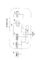
図1には、撮影レンズを通過した被写体像をファインダで観察可能ないわゆる「一眼レフ」タイプの電子カメラシステムに本発明を適用した場合のカメラの構成をブロック図で示している。
【0013】
交換レンズ1は、カメラボディ31に着脱可能な例えばズームレンズである。被写体像を結像させるためのこの交換レンズ1の撮影レンズ群は、前段から順にレンズ101、レンズ2、レンズ4およびレンズ102から構成されており、この撮影レンズ群中のレンズ2とレンズ4の間には絞り機構3が配置されている。この絞り機構3は、絞り駆動回路12の出力に従って動作する絞りモータ10によって駆動制御されるように構成されており、この絞り機構3の絞りの初期位置や停止位置は、これに接続されている絞りエンコーダ7によって検出され、その検出された位置情報はレンズ制御回路14に入力されて上記絞り駆動回路12にフィードバックされるように構成されている。
【0014】
レンズ2は、ズーム駆動回路11の出力に従って動作するレンズモータ9によって駆動制御される。そしてこのレンズ2の初期位置や停止位置は、ズームエンコーダ6によって検出され、その検出された位置情報はレンズ制御回路14に入力され上記ズーム駆動回路11にフィードバックされるように構成されている。一方、レンズ4は、フォーカス駆動回路13の出力に従って動作するフォーカスモータ5によって駆動制御される。フォーカス駆動に従って変化するこのレンズ4の初期位置や停止位置は、フォーカスエンコーダ8によって検出され、その検出された位置情報はレンズ制御回路14に入力され上記フォーカス駆動回路13にフィードバックされるように構成されている。
【0015】
レンズ制御回路14は、フォーカスエンコーダ8、絞りエンコーダ7及びズームエンコーダ6に接続され、それぞれの出力に基づいて、ズーム駆動回路11、絞り駆動回路12及びフォーカス駆動回路13を統括的に制御すると共に、その統括制御に必要な様々な演算等の処理を行うように構成されている。
【0016】
また交換レンズ1のレンズ制御回路14は、通信ライン15と、カメラボディ31側と接触する通信コンタクト16を端面に露出して有し、この通信コンタクト16を介してカメラボディ31と随時通信を行い、交換レンズ1内の種々の回路の制御に反映すると共に、交換レンズ1側の状態をカメラボディ31に逐次送信可能に形成されている。
【0017】
さらにこの交換レンズ1内には、不揮発性メモリ33がレンズ制御回路14からアクセス可能に配置されており、交換レンズ1固有のデータを記憶している。
尚、この例では、上記不揮発性メモリ33は書き換え可能な例えばEEPROMで構成されている。
【0018】
同様に、いわゆるデジタルカメラであるカメラボディ31は次のように構成されている。すなわち、上述の交換レンズ1を通過した破線で示す被写体光が、中央近傍をハーフミラーとする可動ミラー17に入射するように光路上に配置され、更にこの可動ミラー17の中央背面部分にはサブミラー18が破線で示す如く下方にその被写体光を反射するように設けられている。
【0019】
またこのサブミラー18の反射光の方向である鉛直方向には、2つの光学系から成る二像分離のためのセパレータ光学系19が配置されている。この一方の光学系を成すセパレータ光学系19により結像される位置にはラインセンサ20が配置され、このラインセンサ20はラインセンサ駆動回路28に接続されている。そしてこれらサブミラー18、セパレータ光学系19およびラインセンサ20等によって公知技術「位相差法」による焦点検出装置が構成されており、カメラボディ31を統括制御する制御回路35に接続している。
【0020】
カメラボディ31は前述の交換レンズ1と電気的/物理的に接続できるように通信コンタクト39をその端面に露出して有し、この通信コンタクト39と通信ライン38を介して制御回路35と接続している。
【0021】
この制御回路35はラインセンサ駆動回路28を介して入力した信号に基づいて、得られた二像の間隔を求め、フォーカスのずれ量を通信ライン38と通信コンタクト39を介して交換レンズ1側のレンズ制御回路14に送信することができるように構成されている。そしてこのレンズ制御回路14は、合焦位置にレンズを駆動するために、カメラボディ31より送信されたフォーカスのずれ量から交換レンズ1内の撮影レンズ4の駆動量を演算し、前述のフォーカス駆動を行い、適宜なフォーカス調整を行うように構成されている。
【0022】
一方、ミラーダウン状態の可動ミラー17の反射光路(鉛直方向の破線)上には、観察時の視野を規定する焦点板24と、図示しないファインダへ被写体光の一部を導くペンタプリズム25及びファインダ接眼光学系26が図示の如く配置されている。
【0023】
また可動ミラー17の後方にはフォーカルプレーンシャッタ21が、さらに、シャッタ21の後方には光学的なローパスフィルター22及び被写体像を撮像してイメージ信号に変換する撮像素子23がそれぞれ配置されている。シャッタ手段としてのフォーカルプレーンシャッタ21にはシャッタ駆動回路29が接続され、このシャッタ駆動回路の制御によって適宜に開閉駆動される。また可動ミラー17にはミラー駆動回路27が接続され、これによってミラーアップ/ダウン駆動される。
【0024】
可動ミラー17が上昇(ミラーアップと称す)し、フォーカルプレーンシャッタ21が開状態となると、撮像素子23上に被写体像が結像し、所定のタイミング信号によって撮像が開始される。撮像を終了するためフォーカルプレーンシャッタ21が閉状態となると、この撮像素子23の撮像を終了し、撮像素子23の光量蓄積データが画像処理回路42に転送される。撮像素子23は画像処理回路42によって制御され、結像された被写体像をアナログ映像信号に変換処理した後、メモリに記憶する。尚、画像処理回路42についての詳細は後述する(図2参照)。
【0025】
カメラボディ31内の制御回路35にはさらに、ストロボ回路32、表示回路34およびスイッチ入力回路36がそれぞれ接続されており、ストロボ回路32は、被写体照明用に補助光として動作するストロボの発光を駆動制御する。警告手段としても用いる表示回路34は、例えば液晶ユニットを用いた表示出力を駆動制御する。またスイッチ入力回路36は、図示しない各種操作スイッチのそれぞれの状態を検出してこれらの情報を制御回路35に入力する。尚、ここで各種操作スイッチとは、例えば被写体像の露光指示のためのレリーズスイッチなどである。本第1実施形態例のカメラのレリーズスイッチは、押圧により二段階のON状態を有する二段階スイッチとなっている。詳しくは、レリーズスイッチの半押し操作により、最初に1st.レリーズスイッチ(1RSW)がON状態となり、更にこの状態のスイッチを押し込むと2nd.レリーズスイッチ(2RSW)がON状態となるような構造のスイッチ要素で構成されている。よって、カメラ操作者,即ち撮影者によりレリーズスイッチがON操作されると、このカメラの制御回路35はスイッチ入力回路36を介してそれを検出し、撮像素子への露光動作を開始するように制御されている。
【0026】
また、ペンタプリズム25と接眼レンズ26上方には、被写体の輝度を測光する測光センサ37が設けられており、これに接続された測光センサ駆動回路41によって駆動制御され、被写体光の輝度が測光できるように構成されている。つまり、可動ミラー17によって反射された被写体光の輝度がこの測光センサ37で測定可能になっている。
【0027】
交換レンズ1が装着されている場合は、カメラボディ31は通信コンタクト39および通信ライン38を介してその交換レンズ1との通信を行なっている。 なお、カメラボディ31側の電源30は、このカメラボディ31内の回路へ電力を供給すると共に、通信コンタクト39を介して交換レンズ1に対しても電源供給が可能な構成にもなっている。
【0028】
また、測光センサ37のセンサ面に隣接して、図示の集光レンズが設けられており、被写体光をセンサ面に結像している。測光センサ37の視野等については詳しく後述する。
上述のミラー駆動回路27、ラインセンサ駆動回路28、シャッタ駆動回路29、画像処理回路42、測光センサ駆動回路41、表示回路34、ストロボ回路32、スイッチ入力回路36は、それぞれ制御回路35により制御されている。
【0029】
図2には、上述した画像処理回路42の詳細な構成が示されている。この画像処理回路42は、この回路を統括的に制御するコントロール部51と、撮像素子23からのアナログ画像信号をデジタル画像信号に変換するA/D変換部52と、後述する所定の処理を行う画像処理部53と、処理済み信号を一時的に記憶しておくバッファメモリ54と、電子画像の記憶保持のための外部メモリ55から構成されている。
【0030】
画像処理回路42ではカメラボディ31の制御回路35により制御されるコントロール部51の制御によって、画像処理関連の動作を適宜制御している。例えば、撮像素子23は結像された被写体像をアナログ映像信号に変換し、画像処理回路42に出力する。また画像処理回路42では、上記アナログ信号処理信号のデジタル信号への変換をA/D変換部52で行い、「シェーディング補正」、「色補正」等の各種補正や、「画像圧縮」等の処理を含む所定の画像処理を画像処理部53で実行し、上記の処理済み信号をバッファメモリ54に記憶した後、さらに外部メモリ55に転送して記録する。外部メモリ55は、カメラ本体31に対して装着自在であり、電気的に書き換えもでき、カメラ本体31の電源がオフ(OFF)しても電子画像の記憶が保持されるので、電子画像の記録に用いられる。
【0031】
以上説明したバッファメモリ54、外部メモリ55、画像処理回路53、撮像素子23の動作は、カメラボディ31側の制御回路35によって通信制御されているコントロール回路51により制御される。また画像処理部53、バッファメモリ54、外部メモリ55、および補正値等を記憶する外部メモリ55は共通のデータバスで接続されており、各種データの授受が相互に可能な構成となっている。
【0032】
ここで、図3(a)にはカメラのファインダに位置している測光センサ37の被写体に対する視野範囲を示し、詳しくは図3(a)に、AEセンサ等から成る測光手段(測光センサ37)がこの視野範囲に対応して九分割されていることを示している。すなわち、測光センサ37の受光素子は図示する如く9つのパターンに分割されており、このセンサを構成する9個のセンサが視野内の輝度を領域A〜Iの9つの部分でそれぞれ感知し、「被写体輝度」を測光することが可能となっていることがわかる。
【0033】
ところで、本実施形態では、露光前に上記測光センサ37の作動により被写体輝度の測光を行うとともに、露光によって撮像素子23を介して撮像時に撮像データから露光時の被写体の輝度に相当する値をAE評価値(測光評価値)として求め、種々に利用している。
【0034】
図3(b)には、上述の撮像の際にAE評価値を求める場合の測光値の範囲を示している。すなわち、視野範囲の鉛直方向を3つの領域、即ち領域α、領域βおよび領域γに分割して、露光の際の撮像データからAE評価値を求めるように構成されていることがわかる。
【0035】
ここで図3(b)のような領域に分割されているのは、本実施形態のような撮像素子では撮像素子が通常水平方向の撮像データを蓄積、転送することから、水平方向に分割した方がAE評価値を算出しやすいためである。また、図3(a)のように測光センサが分割されているのは、より細かく被写体輝度を検出するとともに、図3(b)に対応した水平方向3分割のAE評価値と比較演算しやすいようにするためである。
【0036】
なお、上記「被写体輝度」とは、視野全体の反射光量を意味している。これによりこの光量を検知することで露光量を決定することができ、更に露光前の被写体輝度測光値と露光の際の被写体輝度に対応するAE評価値を比較することで、シャッタ21が正常に動作したかを検出することができる。
【0037】
以下からは、第1実施形態例の電子カメラに係わる制御について説明する。
まず図4のフローチャートにはカメラシーケンスのメインルーチンを例示する。最初にステップS1において、カメラ内の種々の初期化を行う(S1)。
【0038】
ステップS2において、ダメージフラグの値(1又は0)に基づき、ダメージ、即ち故障の有無を判定し(S2)、もし1である場合には後述するサブルーチン『ダメージ処理』(図8参照)を実行する。一方、0の場合は通常のカメラとしての表示を行い、カメラ動作を行う期間を計時するための表示タイマをここでスタートさせる(S4)。
【0039】
ステップS5において、この表示タイマが満了したか否かを判定し、もし満了した場合には、「スタンバイ」、即ちカメラの待機状態の為の所定の準備を行い(S11)、所定のスタンバイ状態でカメラを待機させる(S12)。一方、まだこの表示タイマが満了していない場合には、ステップS6からS9に至る通常のカメラとしての動作処理いを行う。ステップS6において所定の表示処理を行う(S6)。
【0040】
そして、ステップS7において、カメラが何らかの操作がされたかを判定し(S7)、もし操作された場合にはその操作に対応するような所定のカメラ動作に関する処理を実行してから(S8)、次のステップ9に進む。
ステップ9では、ここで特にレリーズに対し手動操作されたか否かの判定を行い(S9)、操作された場合は次に詳述する『レリーズ処理』(図5参照)を実行してから(S10)、再びステップS5に戻って、前述の表示タイマが満了するまで同様な処理ステップ(S5〜S12)を繰り返す。
【0041】
図5のフローチャートには、上述のサブルーチン『レリーズ処理』の動作手順を示している。すなわち、
ステップS21において、1st.レリーズがON操作されたか否かを判定し(S21)、もし否の場合は上述したメインルーチンにリターンする。 一方、1st.レリーズがON操作された場合には、ステップS22において、被写体に対する焦点検出を行い(S22)、その検出された合焦点までのレンズ駆動を行い(S23)、その後、被写体に対する測光を行う(S24)。
【0042】
尚、この測光は前述の測光センサ37を用いて、測光センサ37の分割された各エリアのセンサが検知した光量に応じた光電流を電圧変換する従来の測光方式を適用して行う。また、測光センサ37を用いて検出された値は制御回路35において一時的に保持され、下記の露出演算に使用する。
【0043】
続いて、ステップS25では、撮像素子に対する最適な露光のための露出演算を行う(S25)。詳しくは、測光センサ37の各センサで測光した被写体輝度と撮像素子23の感度に基づき、次式によって絞り値とシャッタ速度を決定する。すなわち、
EV(露出値)=AV(露出時絞り)+TV(露出時シャッタ速度)
=BV(1st.レリーズ時測光輝度)+X(撮像素子感度)。
【0044】
また、ステップS26においては、2nd.レリーズがON操作されたか否かの判定を行い(S26)、否の場合は、ステップS27で再び1st.レリーズがON操作されたか否かを判定する(S27)。もし否の場合はメインルーチンにリターンするが、1st.レリーズがON操作された場合には、上記ステップS26に戻って再度ステップS26から実行する。
【0045】
後述するサブルーチン『再測光』を実行する(S28)。尚、ここでは1st.レリーズ操作時に測光動作を行うが、1st.レリーズで当該被写体にAEロックおよびフォーカスロックし、2nd.レリーズ操作時にはフレーミングを変えて撮影する可能性があるので、この2nd.レリーズ操作後に再度測光を行う。またこの測光結果は露出演算には利用せず、後述のようにエラー(故障)検出のために用いる。
その後、ステップS29において、露光のためのミラーアップを行い(S29)、ステップS30において、最適露出のための絞りの絞り込み動作を行う(S30)。
【0046】
またステップS31においては、露光のためフォーカルプレーンシャッタを開くように指示を行う。(つまり、フォーカルプレーンシャッタの先幕の走行を開始する)(S31)。そして続くステップS32では撮影のための撮像指示を行う(S32)。具体的には、撮像秒時を画像処理部に送信し撮像開始を指示する。画像処理部は撮像素子で被写体像の撮像動作を開始して、所定撮像秒時後、その撮像素子のアナログ信号を転送し各種の画像処理を行う。このように、所定秒時後、信号の転送を行う電子シャッタに加えて、フォーカルプレーンシャッタにより機械的なシャッタによる被写体光の遮断を行うのは、スミア防止等の為である。そして画像処理部では、撮像信号をA/D変換と各種画像処理を行い、バッファメモリに撮像した画像データを記憶する。なお、本実施形態においては、画像処理の際には前述した図3(b)中のβエリアの輝度値の算出やAE評価データの作成も行われ、同時にバッファメモリに記憶され、その後は、撮像終了と共にβエリアのAE評価データを制御回路へ送信する。尚、ここでの撮像素子23上のβエリアは、図3(a)中の測光センサ37のD,E,Fエリアの総和に相当するものである。このβエリアが横長形状になっている理由は、撮像素子のデータの読出し方法に対応して画像処理部の処理を簡略化するためである。またこのβエリアに対応可能なようにその測光センサの分割エリアを決定している。
【0047】
前述のように本実施形態では、測光センサ37のD,E,Fエリアの露光前の測光値と撮像素子23のβエリアのデータより算出された露光中の測光値とを比較することにより、正常にシャッタ開閉が行われたかどうかを検出可能としている。
【0048】
ステップS33においては、所定の秒時が経過したか否かを行い(S33)、所定時間だけ待機する。その後、ステップS34において、そのシャッタを閉じる指示を行う(つまり、フォーカルプレーンシャッタの後幕の走行を開始する。)(S34)。
【0049】
ステップS35においては、これまでアップされていたミラーをダウン動作させる(S35)。そして、絞りを開放する動作を行う(S36)。
続いて、ステップS37においては、後述するサブルーチン『撮像エラー評価』(図7参照)を実行する(S37)。尚、この撮像エラー評価により正常に撮影又は露光が行われたかが評価・判断される。
【0050】
ステップS38においては、当該被写体の撮像データをメモリ内に記憶することの指示を行うと共に(S38)、ステップS39では、例えば表示手段としての液晶表示デバイス上にその被写体像をモニタ表示する(S39)。そしてメインルーチンにリターンする。
【0051】
図6のフローチャートには、上述のサブルーチン『再測光』の動作手順を示している。すなわち、
まずステップS41において、再度測光しようとする被写体に対応する視野内のエリアの選択を、複数に分割されて構成された測光センサ37から行う(S41)。本実施形態では、中央のエリアであるD,E,Fエリアを選択する。
【0052】
ステップS42では、そのエリアに対応する測光センサで得られた被写体の輝度も測定して(S42)、その輝度に基づき「ファインダAE評価値」を算出する(S43)。そして上述の『レリーズ処理』にリターンする。
尚、ここで言う「ファインダAE評価値」とは、撮影直前の被写体輝度値をファインダ光学系にある測光センサ37を用いて測光した際の測光結果に基づく評価値である。
【0053】
図7のフローチャートには、前述したサブルーチン『撮像エラー評価』の手順を示している。すなわち、
ステップS51においては、露光の際の撮像素子23により得られた輝度に基づくAE評価値(本実施形態では撮像素子23にCCDを用いているので、CCDAE評価値を記すことにする。)と、上記の露光直前に測光センサ37より得られた「ファインダAE評価値」との大小比較を行う(S51)。詳しくは、再測光において被写体輝度からファインダAE評価値があらかじめ算出されているので、これに対して、画像処理部で撮像した画像データに基づくCCDAE評価値を撮像終了後に算出して、制御回路に送信する。ただし、撮像時と再測光時では絞り値が異なるので同一条件に変換してそれらAE評価値を比較する。即ち、下記の評価値BV1,BV2を次式に従って算出し、共に再測光時の絞り値相当の輝度に変換して比較を行う。即ち、
BV1=BV(再測光時のファインダAE評価値)
BV2=BV(撮像時のCCDAE評価値)+{AV1(撮像時の絞り値)
−AV2(再測光時の絞り値)}。
【0054】
ステップS52においては、第1のデータとしての「ファインダ輝度」と第2のデータとしての「CCD輝度」(同様にCCDAE評価値からの算出結果をCCD輝度を記す。)との大小比較を行う(S52)。ここで大きいことは、つまり輝度が明るいことを意味する。すなわち、ファインダ輝度に対してCCD輝度が所定値以上少ない(即ち暗い)場合には、シャッタが開かなかったことが予想される。そこで次のステップS53において、輝度差がその所定値以上であるか否かを判定し(S53)、もし否であればステップS57に進む。一方、ステップS53において所定値以上であった場合は、ステップS54において、シャッタ開エラー表示を行うと共に、撮影が失敗したことを表示し(S54)、ステップS55において、シャッタ開エラーを示すフラグを1にセットする(S55)。
そして、後述するサブルーチン『ダメージ処理』(図8参照)を実行する。
【0055】
ステップS57においては再び、CCD輝度とファインダ輝度との大小比較を行い(S57)、もしCCD輝度がファインダ輝度以下であれば、リターンする。一方ここで、CCD輝度がファインダ輝度以上であれば、次にステップS58において、輝度差が所定値以上であるか否かを判定し(S58)、もし否であればリターンする。
【0056】
そして、ステップS58において所定値以上である場合には、ステップS59において、シャッタ閉エラー表示を行うと共に、撮影が失敗であることを表示し(S59)、ステップS60では、シャッタ閉エラーを示すフラグを1にセットする(S60)。その後、後述するサブルーチン『ダメージ処理』(図8参照)を実行する。すなわち、破線で囲まれた処理ステップでは、ファインダ輝度に対してCCD輝度が所定値以上明るいので、シャッタが閉じなかったことが予想される。
【0057】
このように、上述のような評価基準に従って、露光直前の測光センサ37(AEセンサ)の測光時の被写体輝度と、撮像・露光時の撮像素子出力の輝度とを比較し、両方の輝度の差が所定値より大きかった場合には、シャッタ機構の故障発生と判断し、エラーシーケンス(例えば、シャッタエラー表示)を行うことがわかる。
【0058】
図8のフローチャートに、上述のサブルーチン『ダメージ処理』の動作手順を示している。すなわち、
まずステップS91において、ダメージフラグを1にセットする(S91)。
ステップS92において、いわゆる「シャッタ閉エラー」か否かの判定を行い(S92)、否である場合はステップS99に移行する。
【0059】
一方、ステップS92においてシャッタ閉エラーであった場合に、ステップS93において、そのエラーが一回目であるか否かを判定し(S93)、1回目であった場合には、更に輝度差の評価を行う(S94)。つまり、エラーが一回目、即ち、撮影でエラーとなった場合、特に「シャッタ閉エラー」であれば、メカニカルシャッタの閉状態はスミア防止に用いている故に、このメカニカルシャッタと電子シャッタとを併用していれば、ある程度その映像が使用できる可能性がある。そこでこのような場合には、露出した画像データを救済するために補正処理を行って、その旨を表示して知らせるようにしている。
【0060】
すなわち、続くステップS95において、その画像データの補正処理が可能か否かを判定し(S95)、否である場合はステップS100に移行するが、もし補正可能であれば、ステップS96において補正処理を指示すると共に(S96)、その補正された画像データの記憶指示を行う(S97)。そして更に、シャッタ閉エラーである旨の表示及び、補正した画像データを記憶した旨の表示を行って、次のステップS101に移行する。
【0061】
またステップS99においては、いわゆる「シャッタ開エラー」があるか否かの判定を行い(S99)、否の場合はステップS101に移行する。
ステップS100においては、後述のサブルーチン『再トライ』を実行する(S100)。
【0062】
その後、エラーが有るか否かを判定し(S101)、もし有れば故障発生とみなし、ステップS102にてスタンバイ状態となる(S102)。一方、エラーが無ければ、ステップS103において、ダメージフラグを0にセットし(S103)、エラー表示の消去を行い(S104)、図4のカメラメインシーケンスのスタートから実行する。
【0063】
また図9のフローチャートには、サブルーチン『再トライ』の動作手順を示している。すなわち、
ステップS111において、前述したサブルーチン『再測光』をコールして実行する(S111)。
【0064】
ステップS112では、最適な露光のための露出演算を行う(S112)。続いて、ステップS113において、露光のためのミラーアップを行い(S113)、ステップS114にて、絞りを最適露出のため絞り込み動作させる(S114)。またステップS115においては、露光のためフォーカルプレーンシャッタを開くように指示を行う(S115)。
【0065】
ステップS116において、被写体の所定部分、例えば図3(b)中のβエリアのみにおける撮像を指示する(S116)。つまり、撮像秒時を画像処理部に送信し撮像開始を指示すると、画像処理部は撮像素子で被写体像の撮像動作を開始し、所定撮像秒時後、その撮像素子のアナログ信号を転送し各種の画像処理を前述同様に行う。
【0066】
その後、所定の秒時が経過したか否かを行い、所定時間だけ待機してから(S117)、シャッタを閉じるように指示を行う(S118)。
またステップS119においては、これまでアップされていたミラーをダウン動作させる(S119)。そして絞りを開放する動作を行う(S120)。
ステップS121において、撮像素子23により得られた輝度に基づくCCDAE評価値と、前述の「ファインダAE評価値」との大小比較を前述同様に行う(S121)。
【0067】
ステップS122において、第2のデータとしての「CCD輝度」と、第1のデータとしての「ファインダ輝度」の大小比較を行う(S122)。すなわち、ファインダ輝度に対してCCD輝度が所定値以上少ない(暗い)場合には、再度、シャッタが開かなかったことが予想される。そこで次のステップS123において、輝度差がその所定値以上であるか否かを判定し(S123)、もし否であればステップS124に進み、シャッタ開エラーフラグを0にセットする(S124)。
【0068】
次にステップS125において再び、CCD輝度とファインダ輝度との大小比較を行い(S125)、もしCCD輝度がファインダ輝度以上でなければ、シャッタ閉エラーフラグを0にセットして(S126)、その後、再トライ回数をカウントした後(S136)リターンするが、ステップS125においてCCD輝度がファインダ輝度以上であった場合は、ステップS131に進む。
【0069】
また、上記ステップS123の判定において、輝度差が所定値より大きい場合に、ステップS127で、再トライが一回目であるか否かを判定し、まだ一回目であれば、それまでのエラー表示を続け(S129)、ステップS130に移行する。一方、一回目でなければ、シャッタ開エラーのみ示す表示を行い(S128)、続くステップS130において、シャッタ開エラーを示すフラグを1にセットしてから(S130)、ステップS136に進む。
【0070】
ステップS131においては、CCD輝度がファインダ輝度以上で且つその輝度差が所定値以上であるか否かを判定し(S131)、否であればステップS126に進むが、その輝度差が所定値以上である場合には次のステップS132で、再トライが一回目であるか否かを判定し(S132)、否であればシャッタ閉エラーを示す表示を行い(S134)、一方、まだ一回目であればそれ旨のエラー表示を続ける(S133)。そして、ステップS135で、シャッタ閉エラーを示すフラグを1にセットし(S135)、その後、ステップS136に進む。
【0071】
ここで、エラー表示続行(ステップS129,S133)とは現在の表示を続けて表示することであり、シャッタ開エラー表示(S128)、シャッタ閉エラー表示(S134)とは、撮影失敗表示を消してそれぞれの表示のみとなることを示す。
【0072】
(作用効果1)
このように、第1実施形態例のカメラによれば、例えばシャッタ機構の故障によって例えばシャッタ等の動作不良を起こし、例えば未露光などの不具合が発生した場合においては、本発明の電子カメラのいわゆる「露光不良検出システム」機能が働くことがわかる。
【0073】
例えば、測光等のため測光センサで得られた撮影直前の被写体輝度に関する第1のデータと、撮影時における被写体輝度に関する第2のデータとの差が所定値よりも小さい場合は、撮影動作(露光も含む)が正常に行なわれたか、或いはシャッタが正常に開閉され、未露光等はなかったと判定できる。また、上記第1のデータが第2のデータよりも所定値以上大きい場合には、シャッタが正常に開状態とならず未露光となったと判定でき、反対に、上記第2のデータが第1のデータよりも所定値以上大きい場合には、シャッタが正常に閉状態とならず露光オーバー等が生じたと判定できる。
【0074】
詳しくは、撮像素子であるCCDによって感知した輝度が、ファインダ光学系による輝度に対して所定値以上あれば、例えばシャッタ機構に何らかの異常(故障)が発生したと判定する。そして、上記のように異常判定された状態に対しては、警告を行う。
【0075】
このように、露光時に撮像素子で得られる輝度と、露光直前に輝度の差に基づいて、電子カメラの撮影時の不具合のその原因を判定することが可能となるので、撮影者自身がその原因を追求する面倒がまったくなくなることがわかる。
【0076】
また、従来のカメラのように専用のシャッタ動作に関する専用の検出素子を含んだ検知機構を設置する必要がなくなるので、その検知機構のコスト及びその設置スペースも不要となる。また、未露光時に撮像した画像データは記憶・表示しないので従来に比べて電力消費もかからない。さらに従来の電子スチルカメラのような不要な画像を消去する等の手間もかからなくなる。
【0077】
(第2実施形態例)
次に、「レンズシャッタ式」の電子カメラに本発明を適用した例を挙げて、第2実施形態例として説明する。
図10には、いわゆる「二眼」タイプの形態の電子カメラシステムに本発明を適用した場合のカメラシステム301のブロック構成図が示されている。
【0078】
このタイプのカメラシステム301では、被写体像を結像させるための専用の撮影レンズ群は、前段からレンズ301、レンズ302、レンズ303およびレンズ304にて構成され、この撮影レンズ群中には、セクタシャッタ305が図示の如く配置されている。このセクタシャッタ305は、シャッタ駆動回路306の出力に従って動作するシャッタプランジャ307によって駆動制御され、通常状態での撮像素子311への被写体光の遮光を行い、露光時には撮像素子311への被写体光の光量調整を行うために設けられている。
【0079】
シャッタ手段としてのシャッタ305の動作は、シャッタ検知回路308によって検出され、その検出された情報は制御回路309に入力され上記シャッタ駆動回路306にフィードバックされるように構成されている。また、シャッタ検知回路308は、光検出素子である処のフォトインタラプタ(以下PIと略記する)及びその専用検出回路で構成されており、シャッタが開いたか否かを検出できるようになっている。
【0080】
撮影レンズ群を構成するレンズ302,303は、フォーカスズーム駆動回路310の出力に従って動作するレンズモータ311によって駆動制御されている。またレンズ302の初期位置や停止位置は、ズームエンコーダ312によって検出され、レンズ303の初期位置や停止位置は、フォーカスエンコーダ320によって検出されるように構成されている。そして、それぞれ検出された位置情報は制御回路309に入力された上記フォーカスズーム駆動回路310にフィードバックされる。
また撮影レンズ群の後方には、光学的なローパスフィルタ313と、被写体像を撮像してイメージ信号に変換する撮像素子311が配置されている。
【0081】
以上の如く構成された二眼カメラは、およそ次のように動作する。すなわち、セクタシャッタ305が開いた状態となると、撮像素子23上に被写体像が結像し、所定のタイミング信号によって撮像が開始される。撮像を終了するためにセクタシャッタ305が閉状態となると、撮像素子の撮像を終了し、撮像素子の光量蓄積データが画像処理回路に転送される。撮像素子311は画像処理回路313によって制御され、結像された被写体像をアナログ映像信号に変換処理した後、メモリに記憶する。
スイッチ入力回路314は各種操作スイッチの状態を検出して制御回路に入力する。尚、ここで各種操作スイッチとは、例えばレリーズスイッチなどである。
【0082】
カメラ操作者によりレリーズスイッチがON操作されると、制御回路309はスイッチ入力回路314を介してそれを検出し認識すると、所定の撮像素子への露光動作を開始させる。
またこのカメラ301にも、前述の一眼レフカメラと同様に被写体照明用のストロボ回路315が設けられているので、図示しないストロボの発光が必要な場合には、補助光として動作するように駆動制御される。
【0083】
このカメラでは、撮影レンズ群の上方に、被写体の輝度を測光する為の測光センサ316と、測光センサ316の分光感度を視感度と同じに調整する為の赤外カットフィルタ317とが設けられている。またこの赤外カットフィルタ317に隣接した前方には、撮影レンズ群のレンズ301〜304とほぼ同様に被写体像を測光センサ316に結像するよう配置されて成る結像レンズ318が設けられている。同様に、撮影レンズ群の更に上方にはファインダレンズ319が設けられ、撮影者は被写体像をこのレンズ319(接眼レンズ)を介して観察できる。
【0084】
また、撮影レンズ群の上方には被写体距離測定のための投光回路322と、この投光回路322からの光を平行光束にするための投光レンズ323と、投光レンズの光を受光する受光センサ325と、前述の投光回路の光を受光センサに結像する受光レンズ324が設けられ、測距センサ駆動回路326の制御により、公知の「三角測量の原理」を適用して「アクティブ測距」が可能に構成されている。この測距センサ駆動回路326は制御回路309の統括制御により被写体距離を検出し、制御回路309はその結果に基づいてフォーカスズーム駆動回路310を介した駆動モータ311によってレンズ302を光軸上に平行移動させ、その被写体にピントを合わせる。
またこのカメラボディ301用の電源30は、この二眼カメラ内の各回路へ所定の電力を適宜供給している。
【0085】
図11のフローチャートには、第2実施形態例におけるサブルーチン『レリーズ処理』の動作の手順を示している。すなわち、
ステップS151において、被写体に対する焦点検出を行い(S151)、その検出された合焦点までのレンズ駆動を行い(S152)、その後、被写体に対する測光を行う(S153)。
【0086】
ステップS154では、最適な露光のための露出演算を行う(S154)。続くステップS155においては、シャッタ不良による未露光の時間制限をする未露光リミットタイマを初期値にセットしてから、スタートさせる(S155)。その後ステップS156において、シャッタを開くように指示して駆動させる(S156)。
【0087】
ステップS157においては、例えばPIセンサ(フォトインタラプタ)の出力の大きさに基づき、シャッタの開閉状態を判定する(S157)。もしシャッタが閉じていれば、ステップS158において、未露光リミットタイマの制限時間が満了したか否かを判定し(S158)、まだ満了していなければ再び上記ステップS157に戻って。矢印の如く繰り返す。一方、制限時間が満了すると、シャッタ開エラーの発生を示す表示と共に、撮影(露光)の失敗を示す表示を行う(S159)。そして、シャッタ開エラーフラグを1にセットした後(S160)、エラーがあった場合の処理を実行する。
【0088】
上記ステップS157の判定で、シャッタが開いたと判断した場合には、ステップS162にて撮影のための撮像指示を行う(S162)。
そしてステップS163では、所定の秒時が経過したか否かを行い(S163)、所定時間だけ待機し、その後ステップS164において、そのシャッタを閉じる指示を行う(S164)。
ステップS165においては、これまでの一連の撮像動作を終了する指示を行う(S165)。
【0089】
続いて、ステップS166においては、前述したサブルーチン『撮像エラー評価』(図8参照)と同様の機能をもつサブルーチンを実行する(S166)。尚、この撮像エラー評価により正常に撮影又は露光が行われたかが同様に評価・判断される。
ステップS167においては、当該被写体の撮像データをメモリ内に記憶することの指示を行うと共に(S167)、続くステップS168では、例えば液晶表示デバイス上にその被写体像をモニタ表示する(S168)。そしてメインルーチン(図4参照)にリターンする。
【0090】
(作用効果2)
このように、第2実施形態例の「二眼」タイプのカメラによれば、1つの検出素子を備えてはいるが、この素子自体は単純で且つ設置スペースやコストにはほとんど影響しないものである。
そしてこの例の二眼カメラでも、図11の『レリーズ処理』中のステップS115〜S161の各処理手順が主に加わり、このカメラとしては実質的に第1実施形態例とほぼ同等な作用効果が得られることがわかる。
【0091】
(変形例1)
例えば、前述したと同様に測光手段としての測光センサと、撮像手段としての撮像素子と、2つの異なる光路を通る被写体輝度の輝度を例えば同時に検出してもよく、この場合は、この測光手段が得た輝度出力と撮像手段が得た輝度出力とを同時に取得し、前述した様に比較してその輝度差が所定値よりもが大きい場合に、同様なエラーシーケンスおよびエラー表示を行うように構成してもよい。この場合は、輝度は時間的に同時に検出されるので、より正確である。
【0092】
(その他の変形例)
このほかにも、本発明を適用するに際しそのカメラの種類に伴なう機構的なわずかな相違はある場合にも、本発明は、その要旨を逸脱しない範囲であれば種々の変形実施が可能である。
【0093】
以上、実施形態に基づいて説明してきたが、本明細書中には次のような発明が含まれている。
(1) 被写体像を電気信号に変換する撮像素子をもつ電子カメラにおいて、
被写体の輝度を検出する測光手段と、
上記測光手段の出力から算出した撮影前の被写体輝度に関する第1のデータと、上記撮像素子の出力から算出した撮影時の被写体輝度に関する第2のデータとに基づき、撮影後に露光が正常に行われたか否かを判定する判定手段と、
上記判定手段によって露光が正常に行なわれていないと判定された場合に、警告を行う警告手段と、
を具備する電子カメラを提供できる。
【0094】
(2) 被写体像を電気信号に変換する撮像素子をもつ電子カメラにおいて、
被写体の輝度を検出する測光手段と、
上記測光手段の出力から算出した撮影前の被写体輝度に関する第1のデータと、上記撮像素子の出力から算出した撮影時の被写体輝度に関する第2のデータとを撮影後に比較する比較手段と、
上記比較手段の出力結果に基づいて、露光が正常に行われたか否かを判定する判定手段と、
上記判定手段によって露光が正常に行なわれていないと判定された場合に、警告を行う警告手段と、
を具備する電子カメラを提供できる。
【0095】
(3) 被写体像を電気信号に変換する撮像素子をもつ電子カメラにおいて、
被写体の輝度を検出する測光手段と、
上記撮像素子へ入射する被写体光を遮光するために開閉可能なシャッタ手段と、
撮影前に上記測光手段の出力から算出した撮影前の被写体輝度に関する第1のデータと、上記シャッタ手段を開状態としたときの上記撮像素子の出力から算出した撮影時の被写体輝度に関する第2のデータとを比較する比較手段と、
上記比較手段の比較結果に基づいて、上記シャッタ手段が正常に開閉動作されたか否かを判定する判定手段と、
上記判定手段によって上記シャッタ手段が正常に開閉されていないと判定された場合に、警告動作を行う警告手段と、
を具備する電子カメラを提供できる。
【0096】
(4) 被写体像を電気信号に変換する撮像素子をもつ電子カメラにおいて、
被写体の輝度を検出する測光手段と、
上記撮像素子へ入射する被写体光を遮光するために開閉可能なシャッタ手段と、
上記撮像素子で撮像した画像データを記憶する記憶手段と、
撮影前に上記測光手段の出力から算出したその撮影前の被写体輝度に関する第1のデータと、上記シャッタ手段を開状態にしたときの上記撮像素子の出力から算出した露光時の被写体輝度に関する第2のデータとを比較する比較手段と、
上記判定手段の比較結果に基づいて、上記シャッタ手段が正常に開閉されたか否かを判定する判定手段と、
を具備し、
上記判定手段によって上記シャッタ手段が正常に開閉されていなかったと判定され場合には、上記記憶手段に当該データを記憶しないことを特徴とする電子カメラを提供できる。
【0097】
(5) 上記判定手段は、上記第1のデータと上記第2のデータとの差が所定値よりも小さい場合、撮影が正常に行なわれている、或いは上記シャッタ手段が正常に開閉されていると判定することを特徴とする、(1)〜(4)の何れかに記載の電子カメラを提供できる。
(6) 上記判定手段は、上記第1のデータが上記第2のデータよりも所定値以上大きい場合には、上記シャッタ手段が正常に開状態とならなかったと判定し、上記第2のデータが上記第1のデータよりも所定値以上大きい場合には、上記シャッタ手段が正常に閉状態とならなかったと判定し、
上記警告手段は、上記判定された状態に対して異なる警告を行うことを特徴とする(1)〜(5)の何れかに記載の電子カメラを提供できる。
【0098】
(7) 上記警告手段による警告は、視覚的なエラー表示を行うことを特徴とする、(1)〜(6)の何れかに記載の電子カメラを提供できる。
【0099】
その他にも本明細書中には次の発明も含まれている。例えば、
(8) 電気的に被写体像を記録可能なデジタルカメラであって、
光学的な像を電気的に撮像する撮像手段と、
被写体光の輝度を測光する測光手段と、
撮影以前に上記測光手段から出力された値に基づいた撮影前の被写体輝度に関する第1のデータと、
撮影以後に上記撮像手段から出力された値に基づいた撮影時の被写体輝度に関する第2のデータと、
上記第1のデータと上記第2のデータを比較する比較手段と、
上記比較手段に基づいて露光動作が正常に行われたか否かを判定する判定手段と、
上記判定手段の判定結果に基づいて、撮影が正常に行われなかった場合には、エラー表示を行うエラー表示手段と、
を有することを特徴とするデジタルカメラを提供する。
これで、測光手段(測光センサ)と得られた撮像データからエラー発生の検出を行える。
【0100】
(9) 電気的に被写体像を記録可能なデジタルカメラであって、
光学的な像を電気的に撮像する撮像手段と、
被写体光の輝度を測光する測光手段と、
上記撮像手段と被写体との間に配され、上記被写体光と上記撮像手段の間で遮光可能なシャッタ手段と、
撮影前に上記測光素子の出力された値に基づいた撮影前の被写体輝度に関する第1のデータと、
上記シャッタ手段が開き、上記撮像手段に被写体光が入射したときに上記撮像手段から出力された値に基づいた撮影時の被写体輝度に関する第2のデータと、
上記第1のデータと第2のデータを比較する比較手段と、
上記比較手段に基づいて上記シャッタ手段が正常に開閉されたか否かを判定する判定手段と、
上記撮像手段で撮像した当該被写体に関する画像データを記憶する記憶手段と、
上記判定手段の判定結果に基づいて、上記シャッタ手段が正常に開閉されなかったと判定された場合は、所定のエラー表示を行うと共に、上記記憶手段は当該画像データの記憶動作を行わないことを特徴とするデジタルカメラ。
【0101】
これで、測光手段と撮像手段の輝度差の大きさに基づいてシャッタ手段の異常、すなわち「シャッタエラー」の有無を判定し、エラーが有った場合にはその得られた画像データ(即ち、撮像イメージ)の記憶動作を禁止できる。
【0102】
(10) 上記判定手段は上記第1および上記第2のデータの差が所定閾値より大きい場合には、露光が正常に行われなかったか又は上記シャッタ手段が正常に開閉されなかったと判定することを特徴とする、(8)又は(9)に記載のデジタルカメラを提供できる。
(11) 上記判定手段は、上記第1のデータの方が第2のデータよりも所定閾値以上、即ち測光時の被写体光の方が明るい場合には、上記シャッタ手段の開時のエラー、即ちシャッタが開かなかったと判定し、
上記第1のデータの方が上記第2のデータよりも所定閾値以上、即ち露光時の被写体光の方が暗いことを示す場合には、上記シャッタ手段の閉時のエラー、即ちシャッタが閉じなかったと判定し、
それぞれの判定に基づいたエラー処理を行うことを特徴とする、(9)又は(10)に記載のカメラを提供できる。
【0103】
(12) 電気的に映像を記録可能なデジタルカメラであって、
光学的な像を電気的に撮像する撮像手段と、
被写体光の輝度を測光する測光手段と、
上記撮像手段と被写体の間に配され、上記被写体光と撮像素子の間の遮光可能なシャッタ手段と、
上記シャッタ手段が開いたか否かを検出するシャッタ開検出手段と、
撮影前に上記測光手段の出力された値に基づいた撮影時の被写体輝度に関する第1のデータと、
上記撮像手段で撮像した被写体に関する画像データを記憶する記憶手段と、
上記シャッタ手段が開き、上記撮像手段に被写体光が入射したときに上記撮像手段から出力された値に基づいた撮影時の被写体輝度に関する第2のデータと、
上記第1のデータと上記第2のデータを比較する比較手段と、
上記比較手段に基づいて上記シャッタ手段が正常に開閉されたか否かを判定する判定手段と、
上記撮像手段は、上記シャッタ開検出手段が上記シャッタ手段が開いたことを検出した場合には所定の撮像動作を行い、
上記判定手段の判定結果に基づいて、上記シャッタ手段が正常に開閉されなかった場合には、所定のエラー表示を行い、一方、上記記憶手段は当該被写体の撮像イメージデータの記憶は行わない特徴のデジタルカメラを提供できる。
これで、測光手段と撮像手段とでそれぞれ得られた輝度の差(輝度差)に基づいてシャッタ開検出手段がシャッタエラーの発生を判定し、このエラーの発生があった場合には、当該被写体の撮像イメージの電子的記憶動作を禁止できる。
【0104】
(13) 上記測光手段(AEセンサ)の測光時の被写体輝度と、撮像・露光時の上記撮像素子が出力した被写体輝度とを比較し、両方の被写体輝度の差が所定値より大きかった場合には、シャッタ機構の故障発生と判断して、エラーシーケンス(例えばシャッタエラー表示)を行うことを特徴とするデジタルカメラを提供できる。
【0105】
【発明の効果】
このように、シャッタ機構の故障に起因する未露光などの不具合が発生した場合において、いわゆる「露光不良検出システム」機能を有する本発明の電子カメラにより、専用の検知機構の設置コスト及び設置スペースの無駄がなく、表示の為の無駄な電力消費もせず、撮影者にわかり易く手間のいらない電子カメラを提供することが可能となる。
【図面の簡単な説明】
【図1】図1は、本発明の第1実施形態例としての「一眼レフ」タイプの電子カメラシステムの構成を示すブロック構成図。
【図2】図2は、画像処理回路の詳細な構成を示すブロック構成図。
【図3】 図3(a)〜(b)は被写体の輝度を検出する際の視野を示し、図3(a)は、測光センサの検出範囲が九分割されている構造を示す説明図、図3(b)は、撮像素子の検出範囲が三分割されている構造を示す説明図。
【図4】図4は、第1実施形態例のカメラシーケンスのメインルーチンを示すフローチャート。
【図5】図5は、サブルーチン『レリーズ処理』の動作手順を示すフローチャート。
【図6】図6は、サブルーチン『再測光』の動作手順を示すフローチャート。
【図7】図7は、サブルーチン『撮像エラー評価』の動作手順を示すフローチャート。
【図8】図8は、サブルーチン『ダメージ処理』の動作手順を示すフローチャート。
【図9】図9は、サブルーチン『再トライ』の動作手順を示すフローチャート。
【図10】図10は、本発明の第2実施形態としての「二眼」タイプの電子カメラシステムを示すブロック構成図。
【図11】図11は、同じく第2実施形態におけるサブルーチン『レリーズ処理』の動作手順を示すフローチャート。
【符号の説明】
1…交換レンズ、
2…撮影レンズ(前段)、
3…絞り機構、
4…撮影レンズ(後段)、
5…フォーカスモータ、
6…ズームエンコーダ、
7…絞りエンコーダ、
8…フォーカスエンコーダ、
9…レンズモータ、
10…絞りモータ、
11…ズーム駆動回路、
12…絞り駆動回路、
13…フォーカス駆動回路、
14…レンズ制御回路(交換レンズ側)、
15…通信ライン、
16…通信コンタクト、
17…可動ミラー、
18…サブミラー、
19…セパレータ光学系、
20…ラインセンサ、
21…フォーカルプレーンシャッタ、
22…ローパスフィルタ、
23…撮像素子、
24…焦点板、
25…ペンタプリズム、
26…ファインダ接眼光学系、
27…ミラー駆動回路、
28…ラインセンサ駆動回路、
29…シャッタ駆動回路、
30…電源(カメラボディ側)、
31…カメラボディ、
32…ストロボ回路、
33…不揮発性メモリ、
34…表示回路、
35…制御回路(カメラボディ側)、
36…スイッチ入力回路、
37…測光センサ、
38…通信ライン、
39…通信コンタクト、
41…測光センサ駆動回路、
42…画像処理回路。[0001]
BACKGROUND OF THE INVENTION
The present invention relates to an electronic camera and a digital camera.
[0002]
[Prior art]
In recent years, an electronic still camera called a “digital camera” having an electronic imaging function for forming a subject image on an imaging element such as a CCD or CMOS and electrically recording a still image has begun to be provided. In this type of electronic camera, usually, a captured image is displayed on a monitor to check whether or not the image has been correctly captured. In such a conventional electronic camera, a mechanical shutter unit is provided between the image sensor and the subject image, and the mechanical shutter unit is used in combination with the electrical shutter function of the image sensor, whereby the image sensor There has been proposed an apparatus configured to reduce the influence of smear and the like and to capture a high-quality image.
[0003]
On the other hand, in a conventional camera called a “silver salt camera”, particularly in a so-called “single-lens reflex camera”, the shutter opening and closing operations are electrically detected, and the exposure to the silver salt film is normal. For example, a silver halide film is normally exposed by a detection element for detecting the running state of a shutter mechanism including a focal plane shutter. There has also been proposed one configured to detect and display whether or not it has been broken.
[0004]
[Problems to be solved by the invention]
However, the above-described electronic still camera has the following problems. For example, when a camera is used, it may break down and normal shooting may not be possible mechanically. In response to such a case, an electronic still camera with a monitor display function cannot capture captured images. The image is displayed on the monitor, and the photographer can check whether or not the photographing has been performed normally by checking the image on the monitor.
[0005]
However, in such a case, if a malfunction of the camera occurs, for example, the shutter does not operate, it is necessary for the photographer himself to determine the cause, and in fact, the photographer has his own photographing method (for example, setting) There is a problem that it is difficult to determine whether there is a problem in operation) or whether there is a problem in the operation of the camera mechanism itself. Furthermore, even if the image is a failure due to a malfunction of the camera itself, the image is recorded and displayed in the memory, which is not only wasteful in terms of power consumption, but the photographer has to delete the image record. However, it will take extra time.
[0006]
On the other hand, the conventional silver halide camera has a dedicated detection mechanism for detecting a malfunction of the shutter, so that the abnormality of the shutter mechanism can be automatically detected. For this purpose, a dedicated shutter detection element, for example, Since shutter PI etc. are needed, there exists a problem that it is disadvantageous in the cost and the installation space.
[0007]
Therefore, the object of the present invention is, for example, to detect a malfunction of a shutter or the like, so that there is no waste of installation cost and installation space of a dedicated detection mechanism, etc. It is an object of the present invention to provide an electronic still camera (digital camera) having a function of “exposure defect detection system” that does not require much trouble.
[0008]
[Means for Solving the Problems]
The present invention has been made in view of the above-described situation, and in order to solve the above problems and achieve the object, the electronic camera of the present invention, for example, the luminance of the subject at the time of photometry immediately before photographing (that is, the amount of light reflected from the subject). ) And the brightness of the subject at the time of shooting (that is, the moment of exposure), and the idea is that the operating state (for example, the open / closed state) of the shutter mechanism can be determined by the magnitude of the difference between these brightnesses. It is a thing. If there is a considerable difference in brightness, it is assumed that some trouble has occurred in the camera, and a warning is required to deal with the trouble. The following measures are taken.
[0009]
According to the present invention, in an electronic camera having an imaging device for converting a subject image formed by imaging of subject light passing through a photographing lens into an electrical signal, subject light that passes through the photographing lens and forms an image on the imaging device. Aperture means for limiting the aperture by changing the aperture, and a taking lensAnd the aperture of the aperture meansThe subject light passing throughReceiving lightA photometric means for detecting the brightness of the subject, a shutter means that can be opened and closed to pass and shield the subject light incident on the image sensor, and a pre-exposure subject brightness calculated from the output of the photometric means. 1 and the output of the image sensor when the shutter means is opened.Calculated from exposure levelBased on the second data relating to the subject brightness, the difference in the aperture opening of the aperture meansOf the first and second dataA determination unit that determines whether or not the shutter unit has normally operated by correcting and comparing the difference, and a lift that is determined by the determination unit that the shutter unit is not operating normally are predetermined. An electronic camera equipped with warning means for performing the warning is proposed.
[0010]
Moreover, the determination means includesCorrectedThe electronic camera according to the invention described above is characterized in that when the difference between the first data and the second data is a predetermined value or more, it is determined that the shutter means is not operating normally. To do.
Further, in the above invention, the determination unit determines that the shutter unit is not opened when the first data is determined to be brighter than the second data by a predetermined value or more. Propose an electronic camera.
Further, in the above invention, the determination unit determines that the shutter unit is not closed when it is determined that the first data is darker than the second data by a predetermined value or more. Propose an electronic camera.
The first data is calculated based on a central region of the photometric means, and the second data is calculated based on a central region of the image sensor. Propose the described electronic camera.
Further, the electronic camera according to the invention is proposed, wherein the warning means is an error display means for visually displaying an error.
[0011]
AlsoThe electronic camera described in the invention is characterized in that image data is not recorded when the determination unit determines that the shutter unit is not operating normally.
Further, the electronic camera according to the invention is proposed, wherein the shutter means is a focal plane shutter.
[0012]
DETAILED DESCRIPTION OF THE INVENTION
Hereinafter, a plurality of embodiments according to the present invention will be described and described in detail with reference to related drawings.
(First embodiment)
An electronic camera having at least an AE sensor as a photometric unit of a camera, an image sensor as an imaging unit, and a shutter unit including a shutter will be described as an example.
FIG. 1 is a block diagram showing the configuration of a camera when the present invention is applied to a so-called “single-lens reflex” type electronic camera system capable of observing a subject image that has passed through a photographing lens with a viewfinder.
[0013]
The
[0014]
The
[0015]
The
[0016]
The
[0017]
Further, a
In this example, the
[0018]
Similarly, a
[0019]
In addition, a separator
[0020]
The
[0021]
The
[0022]
On the other hand, on the reflected light path (vertical broken line) of the
[0023]
Further, a
[0024]
When the
[0025]
Further, a
[0026]
In addition, a
[0027]
When the
[0028]
Further, a condensing lens shown in the figure is provided adjacent to the sensor surface of the
The
[0029]
FIG. 2 shows a detailed configuration of the
[0030]
The
[0031]
The operations of the
[0032]
Here, FIG. 3A shows the field of view of the subject of the
[0033]
By the way, in the present embodiment, subject luminance is measured by the operation of the
[0034]
FIG. 3B shows a photometric value range in the case of obtaining the AE evaluation value in the above-described imaging. That is, it can be seen that the vertical direction of the visual field range is divided into three regions, that is, the region α, the region β, and the region γ, and the AE evaluation value is obtained from the imaging data at the time of exposure.
[0035]
3B is divided into regions as shown in FIG. 3B because the image pickup device normally stores and transfers image data in the horizontal direction in the image pickup device as in this embodiment. This is because it is easier to calculate the AE evaluation value. Further, the fact that the photometric sensor is divided as shown in FIG. 3 (a) detects the subject brightness more finely and is easy to compare with the AE evaluation value of the horizontal division corresponding to FIG. 3 (b). It is for doing so.
[0036]
The “subject luminance” means the amount of reflected light in the entire field of view. Thus, the amount of exposure can be determined by detecting this amount of light, and the
[0037]
Hereinafter, control related to the electronic camera of the first embodiment will be described.
First, the main routine of the camera sequence is illustrated in the flowchart of FIG. First, in step S1, various initializations in the camera are performed (S1).
[0038]
In step S2, based on the value (1 or 0) of the damage flag, it is determined whether there is damage, that is, whether there is a failure (S2).8). On the other hand, in the case of 0, display as a normal camera is performed, and a display timer for counting the period of camera operation is started here (S4).
[0039]
In step S5, it is determined whether or not the display timer has expired. If it has expired, a predetermined preparation for "standby", that is, a standby state of the camera is performed (S11). The camera is put on standby (S12). On the other hand, if the display timer has not expired, the normal camera operation process from step S6 to step S9 is performed. In step S6, a predetermined display process is performed (S6).
[0040]
In step S7, it is determined whether or not the camera has been operated (S7). If the camera has been operated, processing relating to a predetermined camera operation corresponding to the operation is executed (S8), and then Proceed to step 9.
In
[0041]
The flowchart of FIG. 5 shows the operation procedure of the above-mentioned subroutine “release process”. That is,
In step S21, 1st. It is determined whether or not the release has been turned ON (S21). If not, the process returns to the main routine described above. On the other hand, 1st. When the release is turned on, in step S22, focus detection is performed on the subject (S22), the lens is driven to the detected focal point (S23), and then photometry is performed on the subject (S24). .
[0042]
This photometry is performed using the above-mentioned
[0043]
Subsequently, in step S25, an exposure calculation for optimal exposure of the image sensor is performed (S25). Specifically, the aperture value and the shutter speed are determined by the following equations based on the subject brightness measured by each sensor of the
EV (exposure value) = AV (exposure stop) + TV (exposure shutter speed)
= BV (photometric brightness at the time of 1st release) + X (image sensor sensitivity).
[0044]
In step S26, 2nd. It is determined whether or not the release has been turned on (S26). If not, 1st. It is determined whether or not the release has been turned ON (S27). If not, the process returns to the main routine. If the release is turned on, the process returns to step S26 and is executed again from step S26.
[0045]
A subroutine “re-photometry” described later is executed (S28). Here, 1st. Metering is performed during the release operation. AE lock and focus lock on the subject with the release, 2nd. Since there is a possibility that the framing may be changed during the release operation, this 2nd. Measure again after the release operation. This photometric result is not used for exposure calculation, but is used for error (fault) detection as described later.
Thereafter, in step S29, the mirror is raised for exposure (S29), and in step S30, the diaphragm is reduced for optimum exposure (S30).
[0046]
In step S31, an instruction is given to open the focal plane shutter for exposure. (That is, the traveling of the front curtain of the focal plane shutter is started) (S31). In the subsequent step S32, an imaging instruction for photographing is given (S32). Specifically, the imaging time is transmitted to the image processing unit to instruct to start imaging. The image processing unit starts an imaging operation of the subject image with the imaging device, and after a predetermined imaging time, transfers an analog signal of the imaging device to perform various image processing. As described above, the object light is blocked by the mechanical shutter by the focal plane shutter in addition to the electronic shutter that transfers the signal after a predetermined time, for the purpose of smear prevention and the like. The image processing unit performs A / D conversion and various types of image processing on the imaging signal, and stores the captured image data in the buffer memory. In the present embodiment, the luminance value of the β area in FIG. 3B and the creation of AE evaluation data are also performed at the time of image processing, and are simultaneously stored in the buffer memory. Upon completion of imaging, AE evaluation data in the β area is transmitted to the control circuit. Note that the β area on the
[0047]
As described above, in the present embodiment, by comparing the photometric value before exposure of the D, E, and F areas of the
[0048]
In step S33, it is determined whether or not a predetermined time has elapsed (S33), and the system waits for a predetermined time. Thereafter, in step S34, an instruction to close the shutter is given (that is, traveling of the rear curtain of the focal plane shutter is started) (S34).
[0049]
In step S35, the mirror that has been up until now is moved down (S35). Then, an operation for opening the aperture is performed (S36).
Subsequently, in step S37, a subroutine “imaging error evaluation” (see FIG. 7) described later is executed (S37). It should be noted that it is evaluated / determined based on this imaging error evaluation whether or not photographing or exposure has been performed normally.
[0050]
In step S38, an instruction to store the imaging data of the subject in the memory is given (S38), and in step S39, the subject image is displayed on a liquid crystal display device as a display unit, for example (S39). . Then, the process returns to the main routine.
[0051]
The flowchart of FIG. 6 shows the operation procedure of the subroutine “re-photometry”. That is,
First, in step S41, the area in the field of view corresponding to the subject to be measured again is selected from the
[0052]
In step S42, the luminance of the subject obtained by the photometric sensor corresponding to the area is also measured (S42), and a “finder AE evaluation value” is calculated based on the luminance (S43). Then, the process returns to the “release process” described above.
The “finder AE evaluation value” referred to here is an evaluation value based on the photometric result when the subject luminance value immediately before photographing is measured using the
[0053]
The flowchart of FIG. 7 shows the procedure of the subroutine “imaging error evaluation” described above. That is,
In step S51, an AE evaluation value based on the luminance obtained by the
BV1 = BV (finder AE evaluation value during re-photometry)
BV2 = BV (CCDAE evaluation value at the time of imaging) + {AV1 (Aperture value at the time of imaging)
-AV2 (aperture value during re-photometry)}.
[0054]
In step S52, the "finder brightness" as the first data and the "CCD brightness" as the second data (similarly, the calculation result from the CCDAE evaluation value is referred to as the CCD brightness) are compared in magnitude ( S52). Here, being large means that the luminance is bright. That is, when the CCD brightness is lower than the finder brightness by a predetermined value or more (that is, dark), it is expected that the shutter has not been opened. Therefore, in the next step S53, it is determined whether or not the luminance difference is equal to or greater than the predetermined value (S53). If not, the process proceeds to step S57. On the other hand, if it is equal to or greater than the predetermined value in step S53, a shutter open error display is performed in step S54, and a shooting failure is displayed (S54). In step S55, a flag indicating a shutter open error is set to 1. (S55).
Then, the subroutine “Damage Processing” (Fig.8).
[0055]
In step S57, the CCD luminance and the finder luminance are compared again (S57). If the CCD luminance is equal to or smaller than the finder luminance, the process returns. On the other hand, if the CCD brightness is greater than or equal to the viewfinder brightness, it is then determined in step S58 whether or not the brightness difference is greater than or equal to a predetermined value (S58), and if not, the process returns.
[0056]
If the value is equal to or greater than the predetermined value in step S58, a shutter close error display is performed in step S59, and the photographing failure is displayed (S59). In step S60, a flag indicating a shutter close error is displayed. Set to 1 (S60). After that, the subroutine “Damage processing” (Fig.8). That is, in the processing steps surrounded by a broken line, the CCD brightness is brighter than a predetermined value with respect to the viewfinder brightness, so it is expected that the shutter has not been closed.
[0057]
Thus, according to the evaluation criteria as described above, the subject luminance at the time of photometry of the photometric sensor 37 (AE sensor) immediately before exposure is compared with the luminance of the image sensor output at the time of imaging / exposure, and the difference between both luminances is compared. Is larger than the predetermined value, it is determined that the shutter mechanism has failed and an error sequence (for example, shutter error display) is performed.
[0058]
Figure8The flowchart shows the operation procedure of the subroutine “damage processing”. That is,
First, in step S91, the damage flag is set to 1 (S91).
In step S92, it is determined whether or not there is a so-called “shutter close error” (S92). If not, the process proceeds to step S99.
[0059]
On the other hand, if it is a shutter closing error in step S92, it is determined in step S93 whether or not the error is the first time (S93), and if it is the first time, the luminance difference is further evaluated. Perform (S94). In other words, if the error is the first time, that is, if an error occurs during shooting, especially if it is a “shutter close error”, the mechanical shutter closed state is used for smear prevention, so this mechanical shutter and electronic shutter are used together. If so, there is a possibility that the video can be used to some extent. Therefore, in such a case, correction processing is performed in order to relieve the exposed image data, and this fact is displayed and notified.
[0060]
That is, in subsequent step S95, it is determined whether or not the image data can be corrected (S95). If not, the process proceeds to step S100. If correction is possible, the correction process is performed in step S96. An instruction is given (S96), and an instruction to store the corrected image data is given (S97). Further, a display indicating that the shutter is closed and a display indicating that the corrected image data is stored are performed, and the process proceeds to the next step S101.
[0061]
In step S99, it is determined whether there is a so-called “shutter opening error” (S99). If not, the process proceeds to step S101.
In step S100, a subroutine “retry” described later is executed (S100).
[0062]
Thereafter, it is determined whether or not there is an error (S101). If there is an error, it is considered that a failure has occurred, and a standby state is set in step S102 (S102). On the other hand, if there is no error, in step S103, the damage flag is set to 0 (S103), the error display is erased (S104), and the process is executed from the start of the camera main sequence of FIG.
[0063]
Also figure9The flowchart shows the operation procedure of the subroutine “retry”. That is,
In step S111, the subroutine “re-photometry” described above is called and executed (S111).
[0064]
In step S112, exposure calculation for optimal exposure is performed (S112). Subsequently, in step S113, mirroring for exposure is performed (S113), and in step S114, the aperture is reduced for optimum exposure (S114). In step S115, an instruction is given to open the focal plane shutter for exposure (S115).
[0065]
In step S116, imaging is instructed only in a predetermined portion of the subject, for example, only the β area in FIG. 3B (S116). In other words, when the imaging time is transmitted to the image processing unit and the start of imaging is instructed, the image processing unit starts the imaging operation of the subject image with the imaging device, and after a predetermined imaging time, the analog signal of the imaging device is transferred and various The image processing is performed in the same manner as described above.
[0066]
Thereafter, it is determined whether or not a predetermined time has elapsed, and after waiting for a predetermined time (S117), an instruction is given to close the shutter (S118).
In step S119, the mirror that has been up until now is moved down (S119). Then, an operation of opening the aperture is performed (S120).
In step S121, the size comparison between the CCDAE evaluation value based on the luminance obtained by the
[0067]
In step S122, the “CCD luminance” as the second data is compared with the “finder luminance” as the first data (S122). That is, when the CCD brightness is lower than the finder brightness by a predetermined value or more (dark), it is expected that the shutter has not been opened again. Therefore, in the next step S123, it is determined whether or not the luminance difference is equal to or greater than the predetermined value (S123). If not, the process proceeds to step S124, and the shutter open error flag is set to 0 (S124).
[0068]
Next, in step S125, the CCD brightness and the finder brightness are compared again (S125). If the CCD brightness is not equal to or higher than the finder brightness, the shutter close error flag is set to 0 (S126), and then the process is restarted. After the number of tries is counted (S136), the process returns. If the CCD brightness is greater than or equal to the finder brightness in step S125, the process proceeds to step S131.
[0069]
If the luminance difference is larger than the predetermined value in the determination in step S123, it is determined in step S127 whether or not the retry is the first time. If it is still the first time, the error display up to that time is displayed. Subsequently (S129), the process proceeds to step S130. On the other hand, if it is not the first time, only the shutter open error is displayed (S128). In the subsequent step S130, a flag indicating the shutter open error is set to 1 (S130), and the process proceeds to step S136.
[0070]
In step S131, it is determined whether or not the CCD brightness is greater than or equal to the finder brightness and the brightness difference is greater than or equal to a predetermined value (S131). If not, the process proceeds to step S126, but the brightness difference is greater than or equal to the predetermined value. If there is, it is determined in the next step S132 whether or not the retry is the first time (S132). If not, a display indicating a shutter close error is displayed (S134). If so, the error display is continued (S133). In step S135, a flag indicating a shutter close error is set to 1 (S135), and then the process proceeds to step S136.
[0071]
Here, the error display continuation (steps S129 and S133) is to display the current display continuously, and the shutter open error display (S128) and the shutter close error display (S134) are to erase the shooting failure display. Indicates that each display is only available.
[0072]
(Operation effect 1)
As described above, according to the camera of the first embodiment, for example, when the malfunction of the shutter or the like occurs due to a failure of the shutter mechanism, for example, when a malfunction such as unexposure occurs, the so-called electronic camera of the present invention is so-called. It can be seen that the “exposure defect detection system” function works.
[0073]
For example, if the difference between the first data relating to the subject brightness immediately before photographing obtained by the photometric sensor for photometry or the like and the second data relating to the subject brightness at the time of photographing is smaller than a predetermined value, the photographing operation (exposure) It is possible to determine that there has been no unexposed or the like. When the first data is larger than the second data by a predetermined value or more, it can be determined that the shutter is not normally opened and is not exposed, and conversely, the second data is the first data. If the data is larger than the predetermined value by a predetermined value or more, it can be determined that the shutter is not normally closed and overexposure has occurred.
[0074]
Specifically, if the brightness sensed by the CCD, which is an image sensor, is greater than or equal to a predetermined value relative to the brightness by the finder optical system, it is determined that some abnormality (failure) has occurred in the shutter mechanism, for example. Then, a warning is given to the state in which the abnormality is determined as described above.
[0075]
As described above, since it is possible to determine the cause of the malfunction at the time of shooting of the electronic camera based on the difference between the brightness obtained by the image sensor at the time of exposure and the brightness immediately before the exposure, the photographer himself can determine the cause. It turns out that the trouble of pursuing is completely eliminated.
[0076]
Further, since it is not necessary to install a detection mechanism including a dedicated detection element related to a dedicated shutter operation as in a conventional camera, the cost of the detection mechanism and its installation space are also unnecessary. In addition, since image data captured at the time of non-exposure is not stored or displayed, power consumption is not required as compared with the conventional case. Further, it is not necessary to delete unnecessary images such as a conventional electronic still camera.
[0077]
(Second Embodiment)
Next, an example in which the present invention is applied to a “lens shutter type” electronic camera will be described as a second embodiment.
Figure101 shows a block configuration diagram of a
[0078]
In this type of
[0079]
The operation of the
[0080]
The
Further, an optical low-
[0081]
The twin-lens camera configured as described above operates in the following manner. That is, when the
The
[0082]
When the release switch is turned on by the camera operator, when the
Since the
[0083]
In this camera, a
[0084]
Further, above the photographing lens group, a light projecting circuit 322 for measuring a subject distance, a
The
[0085]
Figure11This flowchart shows the operation procedure of the subroutine “release process” in the second embodiment. That is,
In step S151, focus detection is performed on the subject (S151), lens driving is performed up to the detected focal point (S152), and then photometry is performed on the subject (S153).
[0086]
In step S154, exposure calculation for optimal exposure is performed (S154). In the following step S155, an unexposed limit timer for limiting the unexposed time due to a shutter failure is set to an initial value and then started (S155). Thereafter, in step S156, the shutter is instructed to be opened and driven (S156).
[0087]
In step S157, for example, the open / close state of the shutter is determined based on the output level of the PI sensor (photo interrupter) (S157). If the shutter is closed, it is determined in step S158 whether or not the time limit of the unexposure limit timer has expired (S158), and if it has not expired, the process returns to step S157 again. Repeat as the arrow. On the other hand, when the time limit expires, a display indicating the occurrence of a shutter opening error and a display indicating a shooting (exposure) failure are performed (S159). Then, after the shutter open error flag is set to 1 (S160), the processing when there is an error is executed.
[0088]
If it is determined in step S157 that the shutter has been opened, an imaging instruction for shooting is issued in step S162 (S162).
Then, in step S163, it is determined whether or not a predetermined time has elapsed (S163), and only a predetermined time is waited. Then, in step S164, an instruction to close the shutter is issued (S164).
In step S165, an instruction to end the series of imaging operations so far is issued (S165).
[0089]
Subsequently, in step S166, a subroutine having the same function as the subroutine “imaging error evaluation” (see FIG. 8) described above is executed (S166). It should be noted that whether or not photographing or exposure has been normally performed is similarly evaluated and judged by this imaging error evaluation.
In step S167, an instruction is given to store the imaging data of the subject in the memory (S167), and in the subsequent step S168, the subject image is displayed on a monitor, for example, on a liquid crystal display device (S168). Then, the process returns to the main routine (see FIG. 4).
[0090]
(Operation effect 2)
As described above, according to the “two-lens” type camera of the second embodiment, the single detection element is provided, but this element itself is simple and has little influence on the installation space and cost. is there.
And even with the twin-lens camera in this example,11In the “release process”, steps S115 to S161 are mainly added, and it is understood that this camera can obtain substantially the same operational effects as those of the first embodiment.
[0091]
(Modification 1)
For example, as described above, the luminance of the subject luminance passing through two different optical paths may be detected simultaneously, for example, the photometric sensor as the photometric means, the image sensor as the imaging means, and the photometric means in this case. The acquired luminance output and the luminance output obtained by the imaging means are acquired simultaneously, and the same error sequence and error display are performed when the luminance difference is larger than a predetermined value as compared with the above. May be. In this case, the luminance is more accurate because it is detected simultaneously in time.
[0092]
(Other variations)
In addition to the above, even when there is a slight difference in mechanism according to the type of camera when the present invention is applied, the present invention can be variously modified without departing from the gist thereof. It is.
[0093]
As mentioned above, although demonstrated based on embodiment, the following invention is contained in this specification.
(1) In an electronic camera having an image sensor that converts a subject image into an electrical signal,
Photometric means for detecting the brightness of the subject;
Based on the first data relating to the subject luminance before photographing calculated from the output of the photometry means and the second data relating to the subject luminance during photographing calculated from the output of the image sensor, exposure is normally performed after photographing. Determining means for determining whether or not
Warning means for giving a warning when it is determined that the exposure is not normally performed by the determination means;
It is possible to provide an electronic camera comprising
[0094]
(2) In an electronic camera having an image sensor that converts a subject image into an electrical signal,
Photometric means for detecting the brightness of the subject;
Comparison means for comparing the first data relating to the subject brightness before photographing calculated from the output of the photometric means and the second data relating to the subject brightness during photographing calculated from the output of the image sensor after photographing;
Determination means for determining whether or not the exposure has been normally performed based on the output result of the comparison means;
Warning means for giving a warning when it is determined that the exposure is not normally performed by the determination means;
It is possible to provide an electronic camera comprising
[0095]
(3) In an electronic camera having an image sensor that converts a subject image into an electrical signal,
Photometric means for detecting the brightness of the subject;
Shutter means that can be opened and closed to shield subject light incident on the image sensor;
First data relating to the subject brightness before photographing calculated from the output of the light metering means before photographing and second subject brightness relating to photographing calculated from the output of the image sensor when the shutter means is opened. A comparison means for comparing the data;
Determination means for determining whether or not the shutter means has been normally opened and closed based on a comparison result of the comparison means;
Warning means for performing a warning operation when the determination means determines that the shutter means is not normally opened and closed;
It is possible to provide an electronic camera comprising
[0096]
(4) In an electronic camera having an image sensor that converts a subject image into an electrical signal,
Photometric means for detecting the brightness of the subject;
Shutter means that can be opened and closed to shield subject light incident on the image sensor;
Storage means for storing image data captured by the image sensor;
First data relating to subject brightness before photographing calculated from the output of the photometry means before photographing and second subject brightness relating to exposure calculated from the output of the image sensor when the shutter means is opened. A comparison means for comparing the data of
Determination means for determining whether or not the shutter means has been normally opened and closed based on a comparison result of the determination means;
Comprising
When the determination means determines that the shutter means is not normally opened and closed, the electronic camera can be provided in which the data is not stored in the storage means.
[0097]
(5) When the difference between the first data and the second data is smaller than a predetermined value, the determination means is normally shooting or the shutter means is normally opened and closed. It is possible to provide the electronic camera according to any one of (1) to (4).
(6) When the first data is larger than the second data by a predetermined value or more, the determination unit determines that the shutter unit has not been normally opened, and the second data is If it is larger than the first data by a predetermined value or more, it is determined that the shutter means has not been normally closed;
The warning means can provide the electronic camera according to any one of (1) to (5), wherein a different warning is given to the determined state.
[0098]
(7) The electronic camera according to any one of (1) to (6), wherein the warning by the warning means performs visual error display.
[0099]
In addition, the present invention includes the following inventions. For example,
(8) A digital camera capable of electrically recording a subject image,
Imaging means for electrically capturing an optical image;
A photometric means for measuring the brightness of the subject light;
First data relating to subject brightness before photographing based on a value output from the photometry means before photographing;
Second data relating to subject brightness at the time of photographing based on a value output from the imaging means after photographing;
A comparing means for comparing the first data and the second data;
Determination means for determining whether or not the exposure operation is normally performed based on the comparison means;
Based on the determination result of the determination means, if shooting is not performed normally, an error display means for displaying an error;
A digital camera is provided.
Thus, the occurrence of an error can be detected from the photometric means (photometric sensor) and the obtained imaging data.
[0100]
(9) A digital camera capable of electrically recording a subject image,
Imaging means for electrically capturing an optical image;
A photometric means for measuring the brightness of the subject light;
A shutter unit disposed between the imaging unit and the subject and capable of blocking light between the subject light and the imaging unit;
First data relating to subject brightness before photographing based on a value output from the photometric element before photographing;
Second data relating to subject brightness at the time of photographing based on a value output from the imaging means when the shutter means is opened and subject light is incident on the imaging means;
A comparing means for comparing the first data and the second data;
Determination means for determining whether or not the shutter means has been normally opened and closed based on the comparison means;
Storage means for storing image data relating to the subject imaged by the imaging means;
When it is determined that the shutter unit has not been normally opened or closed based on the determination result of the determination unit, a predetermined error display is performed and the storage unit does not perform the storage operation of the image data. A digital camera.
[0101]
Now, based on the magnitude of the luminance difference between the photometric means and the imaging means, it is determined whether or not there is an abnormality of the shutter means, that is, “shutter error”. If there is an error, the obtained image data (ie, (Imaged image) storage operation can be prohibited.
[0102]
(10) When the difference between the first data and the second data is greater than a predetermined threshold, the determination means determines that exposure has not been performed normally or the shutter means has not been normally opened / closed. The digital camera according to (8) or (9) can be provided.
(11) If the first data is more than a predetermined threshold value than the second data, that is, if the subject light at the time of photometry is brighter, the determination means determines an error when opening the shutter means, Determine that the shutter did not open,
If the first data is more than a predetermined threshold value than the second data, that is, the subject light at the time of exposure is darker, an error when closing the shutter means, that is, the shutter is not closed. It was determined that
It is possible to provide the camera according to (9) or (10), which performs error processing based on each determination.
[0103]
(12) A digital camera capable of electrically recording video,
Imaging means for electrically capturing an optical image;
A photometric means for measuring the brightness of the subject light;
A shutter means disposed between the imaging means and the subject and capable of shielding light between the subject light and the imaging element;
Shutter opening detecting means for detecting whether or not the shutter means is opened;
First data relating to subject brightness at the time of photographing based on the value output from the photometry means before photographing;
Storage means for storing image data relating to the subject imaged by the imaging means;
Second data relating to subject brightness at the time of photographing based on a value output from the imaging means when the shutter means is opened and subject light is incident on the imaging means;
A comparing means for comparing the first data and the second data;
Determination means for determining whether or not the shutter means has been normally opened and closed based on the comparison means;
The imaging means performs a predetermined imaging operation when the shutter opening detection means detects that the shutter means is opened,
Based on the determination result of the determination unit, when the shutter unit is not normally opened and closed, a predetermined error display is performed, while the storage unit does not store the captured image data of the subject. A digital camera can be provided.
Thus, the shutter opening detection means determines the occurrence of a shutter error based on the difference in luminance (brightness difference) obtained by the photometry means and the imaging means, and if this error occurs, the subject The electronic storage operation of the captured image can be prohibited.
[0104]
(13) When the subject brightness at the time of metering by the photometry means (AE sensor) is compared with the subject brightness output by the image sensor at the time of image capture / exposure, and the difference between both subject brightness is larger than a predetermined value Can provide a digital camera characterized by performing an error sequence (for example, shutter error display) upon determining that the shutter mechanism has failed.
[0105]
【The invention's effect】
As described above, in the case where problems such as unexposure due to the failure of the shutter mechanism occur, the electronic camera of the present invention having a so-called “exposure detection system” function can reduce the installation cost and installation space of the dedicated detection mechanism. It is possible to provide an electronic camera that is not wasted, does not consume unnecessary power for display, and is easy for the photographer to understand.
[Brief description of the drawings]
FIG. 1 is a block diagram showing a configuration of a “single-lens reflex” type electronic camera system as a first embodiment of the present invention.
FIG. 2 is a block configuration diagram showing a detailed configuration of an image processing circuit.
FIGS. 3A to 3B show a field of view when detecting the luminance of a subject, and FIG. 3A is an explanatory diagram showing a structure in which a detection range of a photometric sensor is divided into nine parts; FIG. 3B is an explanatory diagram showing a structure in which the detection range of the image sensor is divided into three parts.
FIG. 4 is a flowchart illustrating a main routine of a camera sequence according to the first embodiment.
FIG. 5 is a flowchart showing an operation procedure of a subroutine “release process”;
FIG. 6 is a flowchart showing an operation procedure of a subroutine “re-photometry”;
FIG. 7 is a flowchart showing an operation procedure of a subroutine “imaging error evaluation”;
FIG. 8 is a flowchart showing an operation procedure of a subroutine “damage processing”;
FIG. 9 is a flowchart showing an operation procedure of a subroutine “retry”;
FIG. 10 is a block diagram showing a “two-lens” type electronic camera system as a second embodiment of the present invention.
FIG. 11 is a flowchart showing an operation procedure of a subroutine “release process” according to the second embodiment.
[Explanation of symbols]
1 ... Interchangeable lens,
2 ... photographic lens (front),
3 ... Aperture mechanism,
4 ... Photography lens (back),
5 ... Focus motor,
6 ... zoom encoder,
7: Aperture encoder,
8: Focus encoder,
9 ... Lens motor,
10: Aperture motor,
11 ... zoom drive circuit,
12 ... Aperture drive circuit,
13: Focus drive circuit,
14 ... Lens control circuit (on the interchangeable lens side),
15 ... communication line,
16. Communication contact,
17 ... movable mirror,
18 ... submirror,
19: Separator optical system,
20 ... line sensor,
21 ... Focal plane shutter,
22 ... Low-pass filter,
23. Image sensor,
24. Focus plate,
25 ... Penta prism,
26 ... finder eyepiece optical system,
27 ... Mirror drive circuit,
28: Line sensor drive circuit,
29 ... Shutter drive circuit,
30 ... Power supply (camera body side),
31 ... Camera body,
32 ... Strobe circuit,
33 ... non-volatile memory,
34. Display circuit,
35 ... Control circuit (camera body side),
36 ... Switch input circuit,
37. Photometric sensor,
38 ... communication line,
39. Communication contact,
41 ... Photometric sensor driving circuit,
42: Image processing circuit.
Claims (8)
撮影レンズを通過して上記撮像素子に結像する被写体光を、絞り開口を変化させて制限する絞り手段と、
撮影レンズ及び上記絞り手段の絞り開口を通過する上記被写体光を受光して、被写体の輝度を検出するための測光手段と、
上記撮像素子へ入射する被写体光を通過及び遮光するために開閉可能なシャッタ手段と、
上記測光手段の出力から算出した露光前の被写体輝度に関する第1のデータと、上記シャッタ手段を開状態にしたときの上記撮像素子の出力から算出した露光レベルより求められる被写体輝度に関する第2のデータとに基づいて、上記絞り手段の絞り開口の違いによる第1のデータと第2のデータの差を補正して比較することにより上記シャッタ手段が正常に動作したか否かを判定する判定手段と、
上記判定手段によって上記シャッタ手段が正常に動作していないと判定された揚合に、所定の警告を行う警告手段と、
を具備することを特徴とする電子カメラ。In an electronic camera having an image sensor for converting a subject image formed by imaging subject light passing through a photographing lens into an electrical signal,
Aperture means for limiting subject light that passes through the imaging lens and forms an image on the image sensor by changing the aperture opening;
Photometric means for detecting the luminance of the subject by receiving the subject light passing through the aperture of the photographing lens and the aperture means ;
Shutter means that can be opened and closed to pass and shield the subject light incident on the image sensor;
First data relating to the subject brightness before exposure calculated from the output of the photometry means and second data relating to subject brightness obtained from the exposure level calculated from the output of the image sensor when the shutter means is opened. And determining means for determining whether or not the shutter means has normally operated by correcting and comparing the difference between the first data and the second data due to the difference in the aperture opening of the diaphragm means. ,
Warning means for giving a predetermined warning when the determination means determines that the shutter means is not operating normally;
An electronic camera comprising:
Priority Applications (1)
| Application Number | Priority Date | Filing Date | Title |
|---|---|---|---|
| JP08396999A JP4327933B2 (en) | 1999-03-26 | 1999-03-26 | Electronic camera |
Applications Claiming Priority (1)
| Application Number | Priority Date | Filing Date | Title |
|---|---|---|---|
| JP08396999A JP4327933B2 (en) | 1999-03-26 | 1999-03-26 | Electronic camera |
Publications (3)
| Publication Number | Publication Date |
|---|---|
| JP2000278559A JP2000278559A (en) | 2000-10-06 |
| JP2000278559A5 JP2000278559A5 (en) | 2006-05-25 |
| JP4327933B2 true JP4327933B2 (en) | 2009-09-09 |
Family
ID=13817380
Family Applications (1)
| Application Number | Title | Priority Date | Filing Date |
|---|---|---|---|
| JP08396999A Expired - Fee Related JP4327933B2 (en) | 1999-03-26 | 1999-03-26 | Electronic camera |
Country Status (1)
| Country | Link |
|---|---|
| JP (1) | JP4327933B2 (en) |
Families Citing this family (3)
| Publication number | Priority date | Publication date | Assignee | Title |
|---|---|---|---|---|
| JP4820499B2 (en) * | 2001-06-27 | 2011-11-24 | Hoya株式会社 | Camera with strobe auto shooting function |
| WO2013114981A1 (en) | 2012-01-30 | 2013-08-08 | 旭硝子株式会社 | Optical member, method for producing same, and article provided with optical member |
| KR101631241B1 (en) * | 2014-11-05 | 2016-06-17 | 주식회사 소모에너지엔테크놀러지 | Self diagnosis method for thermal camera shutter and thermal camera same the using |
-
1999
- 1999-03-26 JP JP08396999A patent/JP4327933B2/en not_active Expired - Fee Related
Also Published As
| Publication number | Publication date |
|---|---|
| JP2000278559A (en) | 2000-10-06 |
Similar Documents
| Publication | Publication Date | Title |
|---|---|---|
| US6839087B1 (en) | Exposure controller of a digital camera | |
| CN101132481B (en) | Digital camera capable of displaying and/or recording movie image | |
| JP2007020125A (en) | Imaging apparatus | |
| JP2003101860A (en) | Image pickup device, photographing image generation method, program and storage medium | |
| CN100518249C (en) | Digital camera having sequential shooting mode | |
| US5038165A (en) | Camera with built-in self-timer | |
| JP4327933B2 (en) | Electronic camera | |
| JP2008203428A (en) | Imaging apparatus | |
| JP2002300442A (en) | Camera system | |
| JP2005341381A (en) | Digital camera | |
| US7313323B2 (en) | Camera system with a photometering device and an external operating device | |
| JP2010074743A (en) | Imaging device | |
| JP4299410B2 (en) | Electronic still camera recording operation control device | |
| JP2001078083A (en) | Exposure time controller for electronic still camera | |
| JP2003101851A (en) | Image pickup device, image pickup method, computer readable storage medium and computer program | |
| JPH1020392A (en) | Camera used for silver salt photographing and electronic image pickup | |
| JPH10142685A (en) | Silver salt photographic and electronic image pickup camera | |
| JP2007101860A (en) | Imaging apparatus | |
| JP4146948B2 (en) | Electronic camera | |
| JP3617057B2 (en) | Electronic still camera | |
| JP2003101873A (en) | Image pickup device, photographing image generation method, program and storage medium | |
| JP2007033997A (en) | Focal point detecting apparatus | |
| JP3229982B2 (en) | Camera capable of split metering | |
| JP2004312432A (en) | Electronic camera | |
| JP2003087648A (en) | Imaging apparatus, photographed image generating method, program, and storage medium |
Legal Events
| Date | Code | Title | Description |
|---|---|---|---|
| A521 | Request for written amendment filed |
Free format text: JAPANESE INTERMEDIATE CODE: A523 Effective date: 20060327 |
|
| A621 | Written request for application examination |
Free format text: JAPANESE INTERMEDIATE CODE: A621 Effective date: 20060327 |
|
| A131 | Notification of reasons for refusal |
Free format text: JAPANESE INTERMEDIATE CODE: A131 Effective date: 20080930 |
|
| A521 | Request for written amendment filed |
Free format text: JAPANESE INTERMEDIATE CODE: A523 Effective date: 20081110 |
|
| A02 | Decision of refusal |
Free format text: JAPANESE INTERMEDIATE CODE: A02 Effective date: 20081216 |
|
| A521 | Request for written amendment filed |
Free format text: JAPANESE INTERMEDIATE CODE: A523 Effective date: 20090209 |
|
| A911 | Transfer to examiner for re-examination before appeal (zenchi) |
Free format text: JAPANESE INTERMEDIATE CODE: A911 Effective date: 20090303 |
|
| TRDD | Decision of grant or rejection written | ||
| A01 | Written decision to grant a patent or to grant a registration (utility model) |
Free format text: JAPANESE INTERMEDIATE CODE: A01 Effective date: 20090519 |
|
| A01 | Written decision to grant a patent or to grant a registration (utility model) |
Free format text: JAPANESE INTERMEDIATE CODE: A01 |
|
| A61 | First payment of annual fees (during grant procedure) |
Free format text: JAPANESE INTERMEDIATE CODE: A61 Effective date: 20090612 |
|
| FPAY | Renewal fee payment (event date is renewal date of database) |
Free format text: PAYMENT UNTIL: 20120619 Year of fee payment: 3 |
|
| FPAY | Renewal fee payment (event date is renewal date of database) |
Free format text: PAYMENT UNTIL: 20120619 Year of fee payment: 3 |
|
| FPAY | Renewal fee payment (event date is renewal date of database) |
Free format text: PAYMENT UNTIL: 20120619 Year of fee payment: 3 |
|
| FPAY | Renewal fee payment (event date is renewal date of database) |
Free format text: PAYMENT UNTIL: 20130619 Year of fee payment: 4 |
|
| LAPS | Cancellation because of no payment of annual fees |