JP4327262B2 - Wiper blade for cleaning automotive glass - Google Patents
Wiper blade for cleaning automotive glass Download PDFInfo
- Publication number
- JP4327262B2 JP4327262B2 JP50797699A JP50797699A JP4327262B2 JP 4327262 B2 JP4327262 B2 JP 4327262B2 JP 50797699 A JP50797699 A JP 50797699A JP 50797699 A JP50797699 A JP 50797699A JP 4327262 B2 JP4327262 B2 JP 4327262B2
- Authority
- JP
- Japan
- Prior art keywords
- wiper blade
- support member
- glass
- wiper
- connecting device
- Prior art date
- Legal status (The legal status is an assumption and is not a legal conclusion. Google has not performed a legal analysis and makes no representation as to the accuracy of the status listed.)
- Expired - Fee Related
Links
Images


Classifications
-
- B—PERFORMING OPERATIONS; TRANSPORTING
- B60—VEHICLES IN GENERAL
- B60S—SERVICING, CLEANING, REPAIRING, SUPPORTING, LIFTING, OR MANOEUVRING OF VEHICLES, NOT OTHERWISE PROVIDED FOR
- B60S1/00—Cleaning of vehicles
- B60S1/02—Cleaning windscreens, windows or optical devices
- B60S1/04—Wipers or the like, e.g. scrapers
- B60S1/32—Wipers or the like, e.g. scrapers characterised by constructional features of wiper blade arms or blades
- B60S1/40—Connections between blades and arms
-
- B—PERFORMING OPERATIONS; TRANSPORTING
- B60—VEHICLES IN GENERAL
- B60S—SERVICING, CLEANING, REPAIRING, SUPPORTING, LIFTING, OR MANOEUVRING OF VEHICLES, NOT OTHERWISE PROVIDED FOR
- B60S1/00—Cleaning of vehicles
- B60S1/02—Cleaning windscreens, windows or optical devices
- B60S1/04—Wipers or the like, e.g. scrapers
- B60S1/32—Wipers or the like, e.g. scrapers characterised by constructional features of wiper blade arms or blades
- B60S1/38—Wiper blades
- B60S1/3848—Flat-type wiper blade, i.e. without harness
- B60S1/3849—Connectors therefor; Connection to wiper arm; Attached to blade
- B60S1/386—Connectors therefor; Connection to wiper arm; Attached to blade made in two halves
-
- B—PERFORMING OPERATIONS; TRANSPORTING
- B60—VEHICLES IN GENERAL
- B60S—SERVICING, CLEANING, REPAIRING, SUPPORTING, LIFTING, OR MANOEUVRING OF VEHICLES, NOT OTHERWISE PROVIDED FOR
- B60S1/00—Cleaning of vehicles
- B60S1/02—Cleaning windscreens, windows or optical devices
- B60S1/04—Wipers or the like, e.g. scrapers
- B60S1/32—Wipers or the like, e.g. scrapers characterised by constructional features of wiper blade arms or blades
- B60S1/38—Wiper blades
- B60S1/3848—Flat-type wiper blade, i.e. without harness
- B60S1/3849—Connectors therefor; Connection to wiper arm; Attached to blade
- B60S1/3865—Connectors having an integral pivot pin for connection with the wiper arm
- B60S1/3867—Connectors having an integral pivot pin for connection with the wiper arm pin formed on the interior of side walls
-
- B—PERFORMING OPERATIONS; TRANSPORTING
- B60—VEHICLES IN GENERAL
- B60S—SERVICING, CLEANING, REPAIRING, SUPPORTING, LIFTING, OR MANOEUVRING OF VEHICLES, NOT OTHERWISE PROVIDED FOR
- B60S1/00—Cleaning of vehicles
- B60S1/02—Cleaning windscreens, windows or optical devices
- B60S1/04—Wipers or the like, e.g. scrapers
- B60S1/32—Wipers or the like, e.g. scrapers characterised by constructional features of wiper blade arms or blades
- B60S1/38—Wiper blades
- B60S1/3848—Flat-type wiper blade, i.e. without harness
- B60S1/3849—Connectors therefor; Connection to wiper arm; Attached to blade
- B60S1/3865—Connectors having an integral pivot pin for connection with the wiper arm
- B60S1/3868—Connectors having an integral pivot pin for connection with the wiper arm pin formed on the exterior of side walls
-
- B—PERFORMING OPERATIONS; TRANSPORTING
- B60—VEHICLES IN GENERAL
- B60S—SERVICING, CLEANING, REPAIRING, SUPPORTING, LIFTING, OR MANOEUVRING OF VEHICLES, NOT OTHERWISE PROVIDED FOR
- B60S1/00—Cleaning of vehicles
- B60S1/02—Cleaning windscreens, windows or optical devices
- B60S1/04—Wipers or the like, e.g. scrapers
- B60S1/32—Wipers or the like, e.g. scrapers characterised by constructional features of wiper blade arms or blades
- B60S1/40—Connections between blades and arms
- B60S1/4006—Connections between blades and arms for arms provided with a hook-shaped end
-
- B—PERFORMING OPERATIONS; TRANSPORTING
- B60—VEHICLES IN GENERAL
- B60S—SERVICING, CLEANING, REPAIRING, SUPPORTING, LIFTING, OR MANOEUVRING OF VEHICLES, NOT OTHERWISE PROVIDED FOR
- B60S1/00—Cleaning of vehicles
- B60S1/02—Cleaning windscreens, windows or optical devices
- B60S1/04—Wipers or the like, e.g. scrapers
- B60S1/32—Wipers or the like, e.g. scrapers characterised by constructional features of wiper blade arms or blades
- B60S1/38—Wiper blades
- B60S2001/3812—Means of supporting or holding the squeegee or blade rubber
- B60S2001/3817—Means of supporting or holding the squeegee or blade rubber chacterised by a backing strip to aid mounting of squeegee in support
- B60S2001/382—Means of supporting or holding the squeegee or blade rubber chacterised by a backing strip to aid mounting of squeegee in support the backing strip being an essentially planar reinforcing strip, e.g. vertebra
-
- B—PERFORMING OPERATIONS; TRANSPORTING
- B60—VEHICLES IN GENERAL
- B60S—SERVICING, CLEANING, REPAIRING, SUPPORTING, LIFTING, OR MANOEUVRING OF VEHICLES, NOT OTHERWISE PROVIDED FOR
- B60S1/00—Cleaning of vehicles
- B60S1/02—Cleaning windscreens, windows or optical devices
- B60S1/04—Wipers or the like, e.g. scrapers
- B60S1/32—Wipers or the like, e.g. scrapers characterised by constructional features of wiper blade arms or blades
- B60S1/38—Wiper blades
- B60S2001/3812—Means of supporting or holding the squeegee or blade rubber
- B60S2001/3822—Means of supporting or holding the squeegee or blade rubber characterised by additional means to prevent longitudinal sliding of squeegee in support, e.g. clips
Description
背景技術
本発明は、請求項1の上位概念部に記載した形式のワイパーブレードにおいて、支持部材がワイパーアームに基づくガラスに対する押圧力のできる均一な分布を、ワイパーブレードによって撫でられる全拭き領域にわたって保証しようとするものである。負荷されていない支持部材(つまりワイパーブレードがガラスに当接していない場合)を相応に湾曲させることによって、ワイパーブレードの運転中、完全にガラスに当接されるワイパー条片の端部は、球面状に湾曲した自動車ガラスの曲率半径が各々のワイパーブレード位置で変化する場合も、緊定された支持部材によってガラスに向かって負荷される。したがってワイパーブレードの湾曲は、拭き領域において拭きたいガラスで測定された最も強い湾曲より少し強くなければならない。したがってこの支持部材は、従来のワイパーブレードで実施されているように(ドイツ連邦共和国特許公開公報第1505357号)、ワイパーブレード内に配置された2つのばねレールを有する複雑な支持ハンガー構造に取って代わるものである。
本発明は、請求項1の上位概念部に記載した形式のワイパーブレードから出発する。この種類の公知のワイパーブレード(ドイツ連邦共和国特許第1028896号)では、支持部材に付属している、長手方向ばねと呼ばれる両ばねレールが、一体的なばねクランプによって、スキッドと呼ばれる拭きゴム条片の長手方向溝内に確保されている。クランプはワイパーブレードの長手方向で長手方向ばねに装着されなければならない。爪を結合するウェブは、ワイパーブレードの背部の厚さに相応して湾曲されていなければならないが、このことは不都合な組付け条件を招く。接続装置の範囲に配置されている中央クランプは、接続装置を貫通部において横断しなければならないが、これは著しい組付けの手間を意味する。なぜならば、両爪の少なくとも1つはその後で初めて成形され得るからである。
発明の利点
請求項1の特徴部に記載の特徴を有する本発明によるワイパーブレードにおいて、完成した保持具部分を、支持部材の、ひいてはワイパーブレードの長手方向延在に対して横断方向にワイパーブレードに引き寄せ、それから互いに結合することが可能である。このような組付けは、コスト面で特に好都合である。なぜならば、場合によっては組付けを自動組付装置によって行うことができるからである。
ワイパーブレードおよび拭き品質を改善するために、支持部材の長手方向延在長さにわたって複数の保持具が配分されていて、互いに間隔を置いて配置されていることが合理的である。
この目的のために、比較的短いワイパーブレードにおいて細長い支持部材の各々の端部区分に保持具を配置すれば十分であり得る。
接続装置が両ばねレールと係合する固定手段を備えており、接続装置が支持部材の長手方向で分割されており、さらに装置部分がそれらの最終的な組付け位置で互いに結合されていると、接続装置に対しても支持部材における合理的な組付けが提供される。
ガラスとは反対側の帯面上にあるワイパー条片の範囲が、ほぼガラスから離れる方向に延びている風よけ条片として形成されていて、各々の保持具に風よけ条片内の凹部が対応配置されていると、大きい走行速度でも効率の高いワイパーブレードを形成できることが特に有利である。
この場合、接続装置に風よけ条片内の凹部が対応配置されていると好都合であり得る。
保持具部分がばねレール外側エッジの露出した区分をクランプ状に取り囲んでいると、単純な組付けにおいてワイパー条片の長手方向溝内にばねレールを確実に確保できる。
この構成は、接続装置を配置した場合も同様の利点において有利である。さらに、組み付けられた接続装置は、ばねレールがそれらの中央区分において長手方向溝内に規定通りに座着することに共に寄与する。
接続装置が2つの装置部分を有しており、各々の装置部分が、支持部材の長手方向に延びていて、ガラスに対して起立するように配置され、かつガラスから離れる方向に延びているフランジ状の付設部を有しており、この付設部にワイバーアームのための接続手段が座着していると、特に単純で安定した、容易に組み付けられる接続装置が提供される。
保持具部分および/または装置部分も互いに掛止可能であると、保持具においても接続装置においても、組付けはさらに単純になる。
本発明のその他の有利な構成が、対応する図面に示した実施例の以下の説明に示されている。
図面
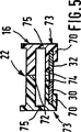
図面において、第1図は、本発明によるワイパーブレードの側面図を示しており、第2図は、第1図に示すワイパーブレードの縮尺を無視した斜視図を示しており、第3図は、第1図に示したワイパーブレードの平面図を示しており、第4図は、第3図に示したワイパーブレードの接続装置を備えた支持部材の線IV−IVに沿った部分断面図を示しており、第5図は、第4図に示した配置構成の線V−Vに沿った断面図を示し、第6図は、第3図に示したワイパーブレードの示した支持部材の線VI−VIに沿った部分断面図を示しており、第7図は、第3図に示した支持部材の線VII−VIIに沿った断面図を90°回転させて示しており、第8図は、第3図に示した支持部材の線VIII−VIIIに沿った断面図を示しており、第9図は、第3図に示した支持部材の線IX−IXに沿った断面図を90°回転させて示しており、第10図は、他の接続装置を備えたワイパーブレードの第5図による断面図を示していて、ワイパーブレードと接続装置の各部が仮組付け位置で表現されており、第11図は、別様に形成された第10図に従う配置構成を示していて、ワイパーブレードと接続装置の各部がそれらの運転位置にあり、第12図は、第9図に示したワイパーブレードの断面図を、ばねレールのための保持具の範囲において保持具の両部分が互いに係止している状態で拡大して示しており、第13図は、第2図に示したワイパーブレードの支持部材の平面図を示している。
実施例の説明
第1図〜第3図に示したワイパーブレード10は、複数部分からなる細長いばね弾性的な支持部材12を有している。支持部材12は、第13図に個別に示されている。この支持部材12の拭きたいガラスとは反対側の表面には接続装置16が配置されており、この接続装置16を利用してワイパーブレード10は、自動車の車体に案内されている駆動されるワイパーアーム18と着脱可能に結合され得る。支持部材12のガラスに向き合わされた下幅には、細長いゴム弾性的なワイパー条片14が長手方向軸線と平行に配置されている。ワイパーアーム18の自由端20には、対向接続手段として働くフックが成形されている。フックはワイパーブレード10の接続装置16に付属している継手ピン22を取り囲んでいる。ワイパーアーム18とワイパーブレード10との間の確保は、アダプタとして形成されたそれ自体公知の確保手段(詳しく図示しない)によって行われる。ワイパーアーム18、ひいてはアーム端部20におけるフックも、矢印24の方向で拭きたいガラスに向かって負荷されている。ガラスの拭きたい表面は、第1図では破線26によって略示されている。破線26はガラス表面の最も強い湾曲を示すものなので、両端部でガラスに当接しているワイパーブレード10の湾曲が、ガラスの最大湾曲より強いことが明瞭に見られる。押圧力下(矢印24)では、ワイパー舌片28を有するワイパーブレードはその全長にわたってガラス表面26に当接している。この場合、帯状のばね弾性的支持部材12内には応力が形成される。この応力は、ワイパー条片14もしくはワイパー舌片28がそれらの全長にわたって自動車ガラスに適切に当接する働きをする。
以下に、本発明によるワイパーブレードの特別の構成について詳述する。第13図には、支持部材12が個別に示されている。ここでは、支持部材12が互いに間隔を置いて配置されている2つのばねレール30および32を有していることが明らかである。第1図〜第3図および第13図に示す実施形態では、両ばねレール30および32と並んで、保持具34および36が支持部材12に付属しているが、これらの保持具の目的については後で説明する。さらに、第13図に略示されているように、支持部材12の中央範囲には接続装置16(破線で示す)が座着している。支持部材12もしくはそのばねレール30および32における接続装置16の配置および固定は、第4図および第5図から最も良く理解される。特に第12図は、ワイパー条片14を基準にした支持部材部分(ばねレール30および32)の配置を示している。第2図および第3図と組み合わせると、ばねレール30および32はワイパーブレード14の互いに向き合う2つの長手方向溝38および40内に位置していることが分かる。これらの長手方向溝38および40は共通平面上にあり、それらの間で支持部材12(第13図)に長手方向スリット42が残っている。この長手方向スリット42を通ってワイパー条片14のウェブ状の狭隘部44が延びている。さらに第12図および第13図から、支持部材12が2つの帯面を有しており、それらのうち一方の帯面46は拭きたいガラスに向けられており、他方の帯面48はガラスとは反対側に向けられていることが分かる。さらに、両ばねレール30および32はそれらの互いに反対側に向けられた長手方向エッジ50および52で、ワイパー条片14の長手方向溝38、40から少なくとも区分的に突出しているのが見られる。この実施例では両ばねレール30および32をそれらの長手方向溝38および40内に確保するために2つの保持具が働く。これらの保持具はそれそれ一方がばねレール30および32の端部区分にある。これにより、両保持具38、40は互いに間隔を置いて配置されている。保持具自体はワイパーブレード10の長手方向延在に対して横断方向に延びていて、両ばねレール30および32の互いに離れている外側エッジ50および52を爪状の付設部54で取り囲んでいる。さらに、保持具34および36はワイパーブレード10の長手方向で分割されているが、これは第2図、第3図および第13図で長手方向継目56によって略示されている。しかし、実用的にはこの長手方向継目56は必ずしも第2図、第3図および第13図に示されているように形成されない。保持具がばねレール30および32に対する確保機能を果たすように、長手方向継目56によって形成された保持具部分33および35は組付け後に互いに固く結合されなければならない。このことは保持具がプラスチックから製造されているか、あるいはまた金属から製造されているかにかかわらず、たとえば溶接、接着または類似の製造技術もしくは組付け技術によって達成され得る。
両保持具部分33および35を互いに結合するための幾つかの実用的な手段の1つを、第12図に基づいて説明する。ここでは、保持具36の保持具部分33および35が爪状の付設部54でばねレール30もしくは32上に座着しているのが見られる。これらの部材は付設部54がばねレール30もしくは32の露出している区分でばねレール外側エッジ50、52を取り囲むように配置されている。保持具部分33はワイパーブレードの長手方向延在に対して横断方向に位置調節されている付設部58でワイパー条片14を上方から把持している。保持具35のU字形延長部60の方は、保持具33の付設部58を取り囲んでいる。U字形延長部60の保持具部分33の側にある自由端区分は、相応に形成されたU字脚部62で保持具部分33のアンダーカット部分64を下方から把持しているので、保持具部分33と35の好ましくない分離は不可能である。両保持具部分を組み付けるために、すなわちこれらを図示された運転位置にもたらすために、両保持具部分は両矢印65および66の方向で互いに向かって押し付けられなければならない。このことはワイパー条片14の弾性を利用して可能である。第12図に従って行われた掛止の後で、両保持具部分33および35はワイパー条片14の残留応力下で、第12図に示された規定の位置に座着する。保持具は、たとえば第5図に示すように形成されてよく、保持具はキャップ状の端壁68でばねレール30および32の端部エッジを覆っている。そうすることによって、ばねレール30および32の鋭い端部エッジによる損傷危険の減少が達成される。さらにこのキャップ状の端部保持具34によって自動車塗装もしくはワイパーブレード自体の破損の危険も低減される。しかし、保持具を第8図の表現に従って形成することも可能である。ここでは端壁はなく、保持具36はばねレール30、32の端部エッジで閉じている。保持具34および36と類似の構成は、接続装置16を有している。第2図、第3図および第5図に示すように、接続装置も同様にワイパーブレードの長手方向で分割されている。このことは継目線72で表される。この継目線72は、爪70でばねレール30および32を取り囲んで支持部材12に当接しているプレート部分74(第5図)も、継手ピン22も貫通している。これにより爪70は接続装置16を支持部材12に保持するための固定手段を形成している。第2図〜第5図に示されている接続装置の実施形態において、この接続装置は、プレート部分74に互いに間隔を置いて設けられているフランジ状の壁75を有しており、これらの壁には同様に分割された継手ピン22のそれぞれ半部が配置されている。フランジ状の壁75は、継目線72で接合可能な2つの装置部分または基部部分73に対応しており、各々1つの装置部分または基部部分73は、支持部材の長手方向に延びていて、ガラスに対して起立するように配置され、かつガラスから離れる方向に延びているフランジ状の付設部(壁75)を有しており、この付設部に継手ピン72によって形成されたワイパーアーム18のための接続手段が座着している。接続装置16の両部分73はそれらの爪70でばねレール外側エッジの露出した中央区分をクランプ状に取り囲んでいる。保持具34および36についてすでに説明されているように、接続装置16の両装置部分73は図示されない手段によって互いに結合可能である。両装置部分の相互の係止や、たとえば溶接または接着も考えられる。
第10図に接続装置116の他の構成が見られる。ここでは両基部部分174には、同様に支持部材の長手方向に延びていて、ガラスに対して起立するように配置され、かつガラスから離れる方向に延びているフランジ状の付設部175が存在しているが、付設部175は互いに直接隣接して相互に結合され得ない。その他の点では、すでに接続装置16の先行の実施例で説明したように、この実施形態においても基部部分174は爪状の付設部154でばねレール30および32の外側長手方向エッジを取り囲んでいる。これらの両基部部分174の固定は、ねじ結合によって実現され得る。この目的のために、両付設部175は、接続装置116を組み付けた状態で互いに合致する孔176をそれぞれ1つ有している。ねじ177は孔176で付設部175を貫通し、継手ピン180のナット部分178と協働する。継手ピン180には、ワイパーアームの相応に形成された自由端がそれ自体公知の形式で接続され得る。しかしまた、それ自体公知の形式で、継手ピンをワイパーアームと固定して結合し、ワイパーアームに付属しているボルト収容部を付設部175に固定することも考えられる。この場合、同時に両基部部分174の固定した結合が実現され得る。
第10図に示した実施形態に著しく近い別の実施形態が、第11図に示されている。第10図に示した実施形態との本質的な違いは、両ばねレール230および232が不等の幅を有していることである。それゆえ、相応の構成も、別の接続装置216の爪状の付設部254を有している。
ここで、本発明によるワイパーブレードの特殊性を、第1図〜第3図および第11図に基づき説明する。これらの図から見られるように、ワイパー条片14は支持部材12のガラスとは反対側の帯面48に、ほぼガラスから離れる方向に延びている風よけ条片200として形成された延長部を有している。このように形成されたワイパーブレードにおいて保持具34、36およびまた接続装置16が有効に配置され得るように、これらの保持具もしくは接続装置には風よけ条片200内の凹部が対応配置されている。
保持具34、36のすべての実施例に共通しているのは、上位概念によるワイパーブレードにおいて保持具がワイパーブレードの長手方向に分割されており、保持具部分33、35が互いに結合されていることである。
上に説明した種々異なる接続装置16もしくは116もしくは216についても、相応の構成が設けられている。BACKGROUND OF THE INVENTION The invention relates to a wiper blade of the type described in the superordinate concept part of
The invention starts from a wiper blade of the type described in the superordinate conceptual part of
Advantages of the invention A wiper blade according to the invention having the features according to
In order to improve the wiper blade and the wiping quality, it is reasonable that a plurality of holders are distributed over the longitudinal extension of the support member and are spaced apart from one another.
For this purpose, it may be sufficient to place a retainer on each end section of the elongated support member in a relatively short wiper blade.
The connecting device comprises fixing means for engaging both spring rails, the connecting device is divided in the longitudinal direction of the support member, and the device parts are joined together in their final assembled position; Reasonable assembly in the support member is also provided for the connection device.
The area of the wiper strip on the side of the belt opposite to the glass is formed as a windshield strip extending in a direction substantially away from the glass. If the recesses are arranged correspondingly, it is particularly advantageous that a highly efficient wiper blade can be formed even at high travel speeds.
In this case, it can be expedient if the recesses in the windbreak strip are correspondingly arranged on the connection device.
If the holder part surrounds the exposed section of the outer edge of the spring rail in a clamping manner, the spring rail can be reliably secured in the longitudinal groove of the wiper strip in a simple assembly.
This configuration is advantageous in the same advantage when the connecting device is arranged. Furthermore, the assembled connecting device together contributes to the seating of the spring rails in the longitudinal grooves in their central section as prescribed.
The connecting device has two device parts, each device part extending in the longitudinal direction of the support member, arranged to stand up against the glass and extending away from the glass If a connecting means for a wiper arm is seated on the attachment portion, a connection device that is particularly simple, stable, and easily assembled is provided.
If the holder part and / or the device part can also be latched together, the assembly is further simplified both in the holder and in the connecting device.
Other advantageous configurations of the invention are shown in the following description of the embodiments shown in the corresponding drawings.
In the drawings, FIG. 1 shows a side view of a wiper blade according to the present invention, FIG. 2 shows a perspective view ignoring the scale of the wiper blade shown in FIG. 1, and FIG. FIG. 4 is a plan view of the wiper blade shown in FIG. 1, and FIG. 4 is a partial sectional view taken along line IV-IV of the support member having the wiper blade connecting device shown in FIG. 5 shows a cross-sectional view along the line V-V of the arrangement shown in FIG. 4, and FIG. 6 shows the line of the support member shown in the wiper blade shown in FIG. FIG. 7 shows a partial cross-sectional view along VI-VI, and FIG. 7 shows the cross-sectional view along the line VII-VII of the support member shown in FIG. Shows a cross-sectional view along the line VIII-VIII of the support member shown in FIG. FIG. 9 shows a sectional view of the supporting member shown in FIG. 3 taken along line IX-IX, rotated by 90 °, and FIG. 10 shows the fifth of the wiper blade provided with another connecting device. FIG. 11 shows a sectional view according to the figure, wherein the wiper blade and each part of the connecting device are represented in a temporarily assembled position, and FIG. 11 shows an arrangement according to FIG. 10 formed differently; FIG. 12 shows a cross-sectional view of the wiper blade shown in FIG. 9 in the range of the holder for the spring rail. FIG. 13 shows a plan view of the support member of the wiper blade shown in FIG. 2.
DESCRIPTION OF THE PREFERRED EMBODIMENT A
In the following, a special configuration of the wiper blade according to the invention will be described in detail. FIG. 13 shows the
One of several practical means for joining the
FIG. 10 shows another configuration of the connecting
Another embodiment, which is very close to the embodiment shown in FIG. 10, is shown in FIG. The essential difference from the embodiment shown in FIG. 10 is that both spring rails 230 and 232 have unequal widths. Therefore, the corresponding configuration also has a claw-
Here, the special characteristics of the wiper blade according to the present invention will be described with reference to FIGS. 1 to 3 and FIG. As can be seen from these figures, the
Common to all the embodiments of the
Corresponding configurations are also provided for the
Claims (10)
保持具(34もしくは36)がワイパーブレード(10)の長手方向で2つの保持具部分(33、35)に分割されており、これらの保持具部分(33、35)が互いに結合されており、これらの保持具部分がばねレール外側エッジ(50、52)の露出した区分をクランプ状に取り囲んでいることを特徴とする、自動車ガラスを清掃するためのワイパーブレード。A wiper blade (10) for cleaning automobile glass, which has an elongated spring elastic support member (12) in a band shape, and a belt surface on the opposite side of the glass of the support member (12) ( 48) holds a connecting device (16) that can be coupled to the driven wiper arm (18), and a strip (46) facing the glass of the support member (12) has an elongated rubber-elastic wiper strip. Spring in which the piece (14) is arranged parallel to the longitudinal axis and the multi-part support member (12) is arranged in two longitudinal grooves (38, 40) of the wiper strip (14) facing each other Rails (30, 32), which are secured by at least one retainer gripping their opposite longitudinal edges from above. In those of the formula,
The holder (34 or 36) is divided into two holder parts (33, 35) in the longitudinal direction of the wiper blade (10), and these holder parts (33, 35) are joined together , Wiper blade for cleaning automotive glass, characterized in that these holder parts clamply surround the exposed section of the outer edge (50, 52) of the spring rail .
Applications Claiming Priority (3)
| Application Number | Priority Date | Filing Date | Title |
|---|---|---|---|
| DE19729864.8 | 1997-07-11 | ||
| DE19729864A DE19729864A1 (en) | 1997-07-11 | 1997-07-11 | Wiper blade for cleaning vehicle windows |
| PCT/DE1998/001787 WO1999002383A1 (en) | 1997-07-11 | 1998-06-30 | Wiper blade for cleaning vehicle glass panes |
Publications (2)
| Publication Number | Publication Date |
|---|---|
| JP2001500091A JP2001500091A (en) | 2001-01-09 |
| JP4327262B2 true JP4327262B2 (en) | 2009-09-09 |
Family
ID=7835473
Family Applications (1)
| Application Number | Title | Priority Date | Filing Date |
|---|---|---|---|
| JP50797699A Expired - Fee Related JP4327262B2 (en) | 1997-07-11 | 1998-06-30 | Wiper blade for cleaning automotive glass |
Country Status (9)
| Country | Link |
|---|---|
| US (1) | US6279191B1 (en) |
| EP (1) | EP0923471B1 (en) |
| JP (1) | JP4327262B2 (en) |
| KR (1) | KR100530433B1 (en) |
| BR (1) | BR9806189A (en) |
| DE (2) | DE19729864A1 (en) |
| ES (1) | ES2175754T3 (en) |
| WO (1) | WO1999002383A1 (en) |
| ZA (1) | ZA986124B (en) |
Families Citing this family (96)
| Publication number | Priority date | Publication date | Assignee | Title |
|---|---|---|---|---|
| US6874195B2 (en) * | 1997-08-12 | 2005-04-05 | Robert Bosch Gmbh | Wiper blade for windows of motor vehicles |
| DE19739256A1 (en) * | 1997-09-08 | 1999-03-11 | Bosch Gmbh Robert | Wiper blade for cleaning windows of motor vehicles |
| DE19856300A1 (en) * | 1998-12-07 | 2000-06-08 | Bosch Gmbh Robert | Wiper blade for windows of motor vehicles |
| DE19906288A1 (en) | 1999-02-15 | 2000-08-17 | Bosch Gmbh Robert | Device for pivot connection of windscreen wiper blade of motor vehicle has wiper strip mounted on spring-elastic band-form support element which on longitudinal sides protrudes over longitudinal sides of wiper strip by edge strips |
| DE19907629A1 (en) * | 1999-02-23 | 2000-08-24 | Bosch Gmbh Robert | Pivot-connection for windscreen wiper blade of motor vehicle has strip-type spring-elastic metal support rail to hold wiper strip and elastic plastic coupling element installed on upper side facing away from windscreen |
| DE19909971A1 (en) * | 1999-03-06 | 2000-09-07 | Bosch Gmbh Robert | Wiper blade for cleaning vehicle windows and method for mounting the wiper blade |
| DE19951363A1 (en) * | 1999-10-26 | 2001-05-03 | Bosch Gmbh Robert | Wiper blade for windows of motor vehicles |
| DE19951971A1 (en) | 1999-10-28 | 2001-05-03 | Bosch Gmbh Robert | Packaging unit for a wiper blade for windshields of motor vehicles housed in this at least in some areas |
| DE19954113A1 (en) * | 1999-11-11 | 2001-05-17 | Bayerische Motoren Werke Ag | Wiper blade for vehicle windscreen wiper has rubber wiper held by claw ends of yoke so that driving wind flows over entire head side to hold wiper lip reliably against window pane even at high speeds |
| DE10000381A1 (en) | 2000-01-07 | 2001-11-22 | Valeo Auto Electric Gmbh | Wiper blade for cleaning windows on vehicles, especially motor vehicles |
| FR2804393B1 (en) * | 2000-01-31 | 2002-05-03 | Valeo Systemes Dessuyage | WIPER SQUEEGEE FOR A WIPER BLADE AND WINDSCREEN WIPER OF A MOTOR VEHICLE EQUIPPED WITH SUCH A SQUEEGEE |
| DE10005418A1 (en) * | 2000-02-08 | 2001-08-09 | Bosch Gmbh Robert | Wiper blade for windows, in particular of motor vehicles, and method for producing the wiper blade |
| DE10007802A1 (en) * | 2000-02-21 | 2001-08-23 | Valeo Auto Electric Gmbh | Wiper strip for wiper blade has projection molded on to at least one long side of it |
| DE10025710A1 (en) * | 2000-02-23 | 2001-08-30 | Bosch Gmbh Robert | Wiper blade for windows, in particular of motor vehicles |
| DE10025706A1 (en) * | 2000-05-25 | 2001-11-29 | Bosch Gmbh Robert | Wiper blade for cleaning vehicle windows |
| US6675433B1 (en) * | 2000-07-06 | 2004-01-13 | Trico Products Corporation | Beam blade wiper assembly having improved wind lift characteristics |
| DE10033779A1 (en) | 2000-07-12 | 2002-05-02 | Valeo Auto Electric Gmbh | Wiper device, in particular for motor vehicles |
| DE10033778A1 (en) | 2000-07-12 | 2002-04-18 | Valeo Auto Electric Gmbh | wiper device |
| DE10034790B4 (en) * | 2000-07-18 | 2016-06-23 | Valeo Auto-Electric Wischer Und Motoren Gmbh | wiper device |
| DE10036122B4 (en) * | 2000-07-25 | 2010-12-16 | Volkswagen Ag | Wiper blade for placement on the wiper arm of a windshield wiper system |
| DE10043427B4 (en) * | 2000-09-04 | 2010-09-23 | Valeo Wischersysteme Gmbh | wiper device |
| ES2243582T3 (en) * | 2000-10-28 | 2005-12-01 | Robert Bosch Gmbh | DEVICE FOR THE CONNECTION OF A WINDSHIELD WIPER ARM WITH A WINDSHIELD WASHER, AS WELL AS A WINDSHIELD WASHER OR A WINDSHIELD WASHER ARM. |
| DE10054235A1 (en) | 2000-11-02 | 2002-05-08 | Valeo Auto Electric Gmbh | wiper device |
| DE10057253A1 (en) * | 2000-11-18 | 2002-05-23 | Bosch Gmbh Robert | Wiper lever for motor vehicle's windscreen wiper system has cap for covering connecting section between wiper blade and wiper arm and in cross section is approximately U-shape and made from elastic plastic |
| DE10065124A1 (en) | 2000-12-28 | 2002-07-04 | Bosch Gmbh Robert | Device for releasably connecting a wiper blade to a wiper arm |
| BR0116592B1 (en) * | 2000-12-28 | 2010-11-16 | A device for the detachable connection of a wiper blade, wiper blade, wiper arm and connecting element for the hinged connection of a wiper blade. | |
| DE10113680B4 (en) * | 2001-03-21 | 2007-01-11 | Robert Bosch Gmbh | Non-iron wiper blade |
| DE10120467A1 (en) | 2001-04-26 | 2002-10-31 | Bosch Gmbh Robert | Wiper blade for cleaning windows, especially of motor vehicles |
| DE60112046T2 (en) | 2001-05-08 | 2006-04-20 | Federal-Mogul S.A. | wiper device |
| FR2843573B1 (en) * | 2002-05-21 | 2007-10-19 | Bosch Gmbh Robert | WINDSCREEN WIPHOLDER HAVING A PORTABLE SURFACE PROFILE ARM AND A DEFLECTOR BRUSH |
| DE10224431A1 (en) | 2002-06-01 | 2003-12-11 | Bosch Gmbh Robert | Packaging for a wiper blade for windows of motor vehicles |
| DE10243287A1 (en) * | 2002-09-18 | 2004-05-19 | Volkswagen Ag | Windshield wipers for vehicles |
| BRPI0410144A (en) | 2003-05-09 | 2006-05-09 | Volkswagen Ag | connecting device for a wiper blade on the wiper arm of a windshield wiper system |
| JP4114564B2 (en) * | 2003-07-16 | 2008-07-09 | 市光工業株式会社 | Vertibra and clip base |
| FR2868748B1 (en) * | 2004-04-07 | 2008-02-01 | Valeo Systemes Dessuyage | END OF WIPER BLADE BROOM END |
| DE102004019157A1 (en) * | 2004-04-21 | 2005-11-10 | Robert Bosch Gmbh | wiper blade |
| CA2514372A1 (en) * | 2004-07-30 | 2006-01-30 | M Management-Tex, Ltd. | Windshield wiper structure |
| FR2879541A1 (en) * | 2004-12-22 | 2006-06-23 | Renault Sas | Windshield wiper for motor vehicle, has blade in longitudinal axis with connecting unit connected to vertebrate, and compression spring arranged in lug exerting longitudinal directional force towards ends of blade |
| KR100624395B1 (en) * | 2004-12-23 | 2006-09-18 | 박춘목 | Window Wiper for Vehicle |
| US7774892B2 (en) | 2005-04-04 | 2010-08-17 | Trico Products Corporation | Wiper coupler and wiper assembly incorporating same |
| CA2541641C (en) | 2005-04-04 | 2014-02-11 | Trico Products Corporation | Wiper coupler and wiper assembly incorporating same |
| FR2885102B1 (en) * | 2005-04-29 | 2016-08-05 | Valeo Systemes Dessuyage | CONNECTOR CONNECTING A WIPER BLADE TO A DRIVE ARM |
| CN2832607Y (en) * | 2005-05-11 | 2006-11-01 | 黄椿庭 | Soft keel rain wiper without supporting point |
| KR100813643B1 (en) * | 2005-11-30 | 2008-03-14 | 에이디엠이십일 주식회사 | Wiper blade |
| KR100699187B1 (en) * | 2005-11-30 | 2007-03-23 | 에이디엠이십일 주식회사 | Wiper blade |
| KR100733623B1 (en) * | 2005-12-05 | 2007-06-29 | 에이디엠이십일 주식회사 | Wiper blade |
| WO2007122570A2 (en) * | 2006-04-21 | 2007-11-01 | Teklas Kaucuk Sanayi Ve Ticaret A.S. | A profile for windshield wipers of vehicles |
| EP1854685B1 (en) * | 2006-05-08 | 2009-06-24 | Federal-Mogul S.A. | A windscreen wiper device |
| ES2332665T3 (en) * | 2006-07-04 | 2010-02-10 | Federal-Mogul S.A. | WINDSHIELD CLEANING DEVICE. |
| DE102006031514A1 (en) * | 2006-07-07 | 2008-01-10 | Robert Bosch Gmbh | Connection element for a wiper blade |
| US7464434B2 (en) * | 2007-03-15 | 2008-12-16 | Fu Gang Co., Ltd. | Securing device for a windscreen wiper connector |
| KR100888013B1 (en) * | 2007-05-30 | 2009-03-09 | 동양기전 주식회사 | Assembly for wiper blade for cleaning windows of motor vehicles |
| KR101098004B1 (en) | 2009-08-26 | 2011-12-22 | 주식회사 캐프 | Multi-adapter of vehicle wiper |
| ES2701435T3 (en) | 2009-08-27 | 2019-02-22 | Trico Products Corp | Windshield wiper assembly |
| US8397341B2 (en) | 2010-05-13 | 2013-03-19 | Trico Products Corporation | Beam blade windshield wiper assembly |
| US8261403B2 (en) | 2010-05-13 | 2012-09-11 | Trico Products Corporation | Beam blade windshield wiper assembly |
| RU2554731C2 (en) | 2010-06-22 | 2015-06-27 | Теклас Каучук Санайи Ве Тикарет А.С. | Windshield wiper |
| US8495787B2 (en) | 2010-08-03 | 2013-07-30 | Rally Manufacturing, Inc. | Windshield wiper |
| KR101170905B1 (en) * | 2010-09-10 | 2012-08-06 | 김인규 | Connecting unit for hook wiper arm and flat wiper blade with the same |
| USD706200S1 (en) | 2010-09-22 | 2014-06-03 | Pylon Manufacturing Corporation | Windshield wiper cover |
| KR101036579B1 (en) * | 2010-10-27 | 2011-05-24 | 주식회사 캐프 | Wiper device |
| USD685712S1 (en) | 2011-03-23 | 2013-07-09 | Kcw Corporation | Wiper |
| US9457768B2 (en) | 2011-04-21 | 2016-10-04 | Pylon Manufacturing Corp. | Vortex damping wiper blade |
| US9174609B2 (en) | 2011-04-21 | 2015-11-03 | Pylon Manufacturing Corp. | Wiper blade with cover |
| WO2013016493A1 (en) | 2011-07-28 | 2013-01-31 | Pylon Manufacturing Corp. | Windshield wiper adapter, connector and assembly |
| US8806700B2 (en) | 2011-07-29 | 2014-08-19 | Pylon Manufacturing Corporation | Wiper blade connector |
| US9108595B2 (en) | 2011-07-29 | 2015-08-18 | Pylon Manufacturing Corporation | Windshield wiper connector |
| MX347284B (en) | 2011-07-29 | 2017-04-21 | Pylon Mfg Corp | Windshield wiper connector. |
| IN2014CN04382A (en) | 2011-11-18 | 2015-09-04 | Federal Mogul Corp | |
| US10723322B2 (en) | 2012-02-24 | 2020-07-28 | Pylon Manufacturing Corp. | Wiper blade with cover |
| US20130219649A1 (en) | 2012-02-24 | 2013-08-29 | Pylon Manufacturing Corp. | Wiper blade |
| CA2865292C (en) | 2012-02-24 | 2018-03-13 | Pylon Manufacturing Corp. | Wiper blade |
| KR101433220B1 (en) | 2012-06-25 | 2014-08-25 | 주식회사 캐프 | A Wiper Blade Assembly |
| US10829092B2 (en) | 2012-09-24 | 2020-11-10 | Pylon Manufacturing Corp. | Wiper blade with modular mounting base |
| USD702618S1 (en) | 2012-11-15 | 2014-04-15 | Trico Products Corporation | Wiper blade coupler |
| US9221429B2 (en) | 2012-11-15 | 2015-12-29 | Trico Products Corporation | Wiper coupler assembly and wiper assembly incorporating same |
| US9533655B2 (en) | 2012-12-04 | 2017-01-03 | Trico Products Corporation | Wiper coupler adapter and wiper assembly incorporating same |
| US9260084B2 (en) | 2013-01-03 | 2016-02-16 | Trico Products Corporation | Wiper coupler adapter and wiper assembly incorporating same |
| US10166951B2 (en) | 2013-03-15 | 2019-01-01 | Pylon Manufacturing Corp. | Windshield wiper connector |
| US9227599B2 (en) | 2013-05-02 | 2016-01-05 | Trico Products Corporation | Mounting assembly for wiper blade and wiper arm |
| KR101474838B1 (en) | 2013-07-01 | 2014-12-22 | 주식회사 캐프 | A Wiper Blade Assembly |
| US9493140B2 (en) | 2013-12-02 | 2016-11-15 | Trico Products Corporation | Coupler assembly for wiper assembly |
| US9505380B2 (en) | 2014-03-07 | 2016-11-29 | Pylon Manufacturing Corp. | Windshield wiper connector and assembly |
| US9539987B2 (en) | 2014-04-01 | 2017-01-10 | Trico Products Corporation | Wiper adapter and wiper assembly incorporating the same |
| US9434355B2 (en) | 2014-04-01 | 2016-09-06 | Trico Products Corporation | Wiper adapter and wiper assembly incorporating the same |
| US9663071B2 (en) | 2014-05-29 | 2017-05-30 | Trico Products Corporation | Wiper adapter and wiper assembly incorporating same |
| CN105459962B (en) * | 2014-06-06 | 2020-07-31 | 罗伯特·博世有限公司 | Wiper blade |
| USD787308S1 (en) | 2014-10-03 | 2017-05-23 | Pylon Manufacturing Corp. | Wiper blade package |
| USD777079S1 (en) | 2014-10-03 | 2017-01-24 | Pylon Manufacturing Corp. | Wiper blade frame |
| US10363905B2 (en) | 2015-10-26 | 2019-07-30 | Pylon Manufacturing Corp. | Wiper blade |
| WO2017201470A1 (en) | 2016-05-19 | 2017-11-23 | Pylon Manufacturing Corp. | Windshield wiper connector |
| US10661759B2 (en) | 2016-05-19 | 2020-05-26 | Pylon Manufacturing Corporation | Windshield wiper connector |
| US10766462B2 (en) | 2016-05-19 | 2020-09-08 | Pylon Manufacturing Corporation | Windshield wiper connector |
| US11040705B2 (en) | 2016-05-19 | 2021-06-22 | Pylon Manufacturing Corp. | Windshield wiper connector |
| EP3458315B1 (en) | 2016-05-19 | 2021-09-08 | Pylon Manufacturing Corp. | Windshield wiper blade |
| FR3069508B1 (en) * | 2017-07-26 | 2020-09-04 | Valeo Systemes Dessuyage | VEHICLE WIPER BLADE |
Family Cites Families (14)
| Publication number | Priority date | Publication date | Assignee | Title |
|---|---|---|---|---|
| US3390416A (en) * | 1946-06-15 | 1968-07-02 | Trico Products Corp | Windshield wiper |
| DE1028896B (en) | 1954-06-24 | 1958-04-24 | Avog Elektro Und Feinmechanik | Wiper rail for windshield wiper |
| FR1239780A (en) * | 1958-11-08 | 1960-08-26 | Rau Swf Autozubehoer | Windshield wiper blade, in particular of motor vehicles |
| US3116507A (en) * | 1960-05-02 | 1964-01-07 | Trico Products Corp | Windshield wiper system |
| US3093856A (en) * | 1960-07-01 | 1963-06-18 | Trico Products Corp | Windscreen wipers |
| US3192551A (en) * | 1964-08-31 | 1965-07-06 | Walter D Appel | Windshield wiper blade assembly |
| DE1505357A1 (en) | 1965-01-23 | 1969-05-29 | Otto Bloetz | Vehicle for the transport of powdery bulk goods |
| DE1505397A1 (en) | 1965-05-07 | 1969-10-30 | Bosch Gmbh Robert | Windshield wipers for vehicles |
| US3408678A (en) * | 1966-08-17 | 1968-11-05 | Roy E. Linker | Windshield wiper assembly |
| US3430285A (en) * | 1968-01-31 | 1969-03-04 | Daco Inc | Holder for windshield wiper blade |
| DE2313689A1 (en) * | 1973-03-20 | 1974-10-03 | Bosch Gmbh Robert | RELEASABLE CONNECTION BETWEEN THE WIPER BLADE AND THE WIPER ARM OF A WIPER SYSTEM |
| FR2222853A5 (en) * | 1973-03-21 | 1974-10-18 | Bosch Gmbh Robert | |
| FR2486002B1 (en) * | 1980-07-07 | 1985-06-21 | Marchal Equip Auto | WINDSCREEN WIPER COMPRISING AN ADD-ON ARM, IN PARTICULAR FOR A MOTOR VEHICLE |
| GB8726140D0 (en) * | 1987-11-07 | 1987-12-09 | Wright C W | Wiper blades |
-
1997
- 1997-07-11 DE DE19729864A patent/DE19729864A1/en not_active Withdrawn
-
1998
- 1998-06-30 JP JP50797699A patent/JP4327262B2/en not_active Expired - Fee Related
- 1998-06-30 DE DE59803715T patent/DE59803715D1/en not_active Expired - Lifetime
- 1998-06-30 BR BR9806189-5A patent/BR9806189A/en not_active IP Right Cessation
- 1998-06-30 ES ES98941250T patent/ES2175754T3/en not_active Expired - Lifetime
- 1998-06-30 EP EP98941250A patent/EP0923471B1/en not_active Expired - Lifetime
- 1998-06-30 US US09/242,869 patent/US6279191B1/en not_active Expired - Lifetime
- 1998-06-30 WO PCT/DE1998/001787 patent/WO1999002383A1/en active IP Right Grant
- 1998-06-30 KR KR10-1999-7002013A patent/KR100530433B1/en not_active IP Right Cessation
- 1998-07-10 ZA ZA9806124A patent/ZA986124B/en unknown
Also Published As
| Publication number | Publication date |
|---|---|
| ES2175754T3 (en) | 2002-11-16 |
| JP2001500091A (en) | 2001-01-09 |
| KR100530433B1 (en) | 2005-11-23 |
| KR20000068533A (en) | 2000-11-25 |
| US6279191B1 (en) | 2001-08-28 |
| ZA986124B (en) | 2000-01-10 |
| EP0923471A1 (en) | 1999-06-23 |
| DE19729864A1 (en) | 1999-01-14 |
| WO1999002383A1 (en) | 1999-01-21 |
| BR9806189A (en) | 1999-11-16 |
| EP0923471B1 (en) | 2002-04-10 |
| DE59803715D1 (en) | 2002-05-16 |
Similar Documents
| Publication | Publication Date | Title |
|---|---|---|
| JP4327262B2 (en) | Wiper blade for cleaning automotive glass | |
| JP4001638B2 (en) | Wiper blades used in automotive window glass | |
| JP4020978B2 (en) | Wiper blade for cleaning car window glass | |
| KR100622840B1 (en) | Wiper blade for cleaning vehicle panes and method for mounting said wiper blade | |
| US6397428B2 (en) | Wiper blade for motor vehicle windows with support having connection device with projections and welding connection | |
| JP4262310B2 (en) | Wiper blade for automotive window glass | |
| EP1876074B1 (en) | Windshield wiper device | |
| US8756748B2 (en) | Windscreen wiper device | |
| US7028368B2 (en) | Wiper blade assembly for motor vehicle | |
| KR100501753B1 (en) | Wiper blades for windshields of automobiles | |
| JP2004512223A (en) | Device for pivotally connecting a wiper blade for cleaning a windshield to a wiper arm in a detachable manner | |
| JP2001500090A (en) | Wiper device used for windshield glass of automobiles | |
| MX2008013814A (en) | A windscreen wiper device. | |
| CZ296865B6 (en) | Wiper blade for glazed surfaces, particularly glazed surfaces of motor vehicles | |
| JP2002537168A (en) | Device for hinged connection of wiper blade and wiper arm for automotive window glass | |
| JP2005521596A (en) | A wiper lever comprising a driven wiper arm and a wiper blade pivotally mounted on the wiper arm for cleaning glass, particularly automobile glass | |
| WO2007122095A1 (en) | A windscreen wiper device | |
| US9415750B2 (en) | Windscreen wiper device | |
| US20170136999A1 (en) | A windscreen wiper device | |
| KR100840000B1 (en) | Assembly for wiper blade for cleaning windows of motor vehicles | |
| EP3494016B1 (en) | Windscreen wiper device | |
| KR100616259B1 (en) | wiper blade | |
| RU2012507C1 (en) | Windshield wiper and method of its assembly | |
| US20180105142A1 (en) | Windscreen wiper device | |
| CA3092872A1 (en) | Hybrid windshield wiper blade |
Legal Events
| Date | Code | Title | Description |
|---|---|---|---|
| A621 | Written request for application examination |
Free format text: JAPANESE INTERMEDIATE CODE: A621 Effective date: 20050629 |
|
| A131 | Notification of reasons for refusal |
Free format text: JAPANESE INTERMEDIATE CODE: A131 Effective date: 20061205 |
|
| A601 | Written request for extension of time |
Free format text: JAPANESE INTERMEDIATE CODE: A601 Effective date: 20070305 |
|
| A602 | Written permission of extension of time |
Free format text: JAPANESE INTERMEDIATE CODE: A602 Effective date: 20070423 |
|
| A02 | Decision of refusal |
Free format text: JAPANESE INTERMEDIATE CODE: A02 Effective date: 20070717 |
|
| A521 | Written amendment |
Free format text: JAPANESE INTERMEDIATE CODE: A523 Effective date: 20071113 |
|
| A911 | Transfer of reconsideration by examiner before appeal (zenchi) |
Free format text: JAPANESE INTERMEDIATE CODE: A911 Effective date: 20071129 |
|
| A912 | Removal of reconsideration by examiner before appeal (zenchi) |
Free format text: JAPANESE INTERMEDIATE CODE: A912 Effective date: 20071206 |
|
| A601 | Written request for extension of time |
Free format text: JAPANESE INTERMEDIATE CODE: A601 Effective date: 20090311 |
|
| A602 | Written permission of extension of time |
Free format text: JAPANESE INTERMEDIATE CODE: A602 Effective date: 20090323 |
|
| A01 | Written decision to grant a patent or to grant a registration (utility model) |
Free format text: JAPANESE INTERMEDIATE CODE: A01 |
|
| A61 | First payment of annual fees (during grant procedure) |
Free format text: JAPANESE INTERMEDIATE CODE: A61 Effective date: 20090611 |
|
| FPAY | Renewal fee payment (event date is renewal date of database) |
Free format text: PAYMENT UNTIL: 20120619 Year of fee payment: 3 |
|
| R150 | Certificate of patent or registration of utility model |
Free format text: JAPANESE INTERMEDIATE CODE: R150 |
|
| FPAY | Renewal fee payment (event date is renewal date of database) |
Free format text: PAYMENT UNTIL: 20130619 Year of fee payment: 4 |
|
| R250 | Receipt of annual fees |
Free format text: JAPANESE INTERMEDIATE CODE: R250 |
|
| R250 | Receipt of annual fees |
Free format text: JAPANESE INTERMEDIATE CODE: R250 |
|
| R250 | Receipt of annual fees |
Free format text: JAPANESE INTERMEDIATE CODE: R250 |
|
| LAPS | Cancellation because of no payment of annual fees |