JP4326999B2 - Image processing system - Google Patents
Image processing system Download PDFInfo
- Publication number
- JP4326999B2 JP4326999B2 JP2004106853A JP2004106853A JP4326999B2 JP 4326999 B2 JP4326999 B2 JP 4326999B2 JP 2004106853 A JP2004106853 A JP 2004106853A JP 2004106853 A JP2004106853 A JP 2004106853A JP 4326999 B2 JP4326999 B2 JP 4326999B2
- Authority
- JP
- Japan
- Prior art keywords
- image processing
- processing system
- light
- glass
- light source
- Prior art date
- Legal status (The legal status is an assumption and is not a legal conclusion. Google has not performed a legal analysis and makes no representation as to the accuracy of the status listed.)
- Expired - Fee Related
Links
Images


Classifications
-
- B—PERFORMING OPERATIONS; TRANSPORTING
- B60—VEHICLES IN GENERAL
- B60S—SERVICING, CLEANING, REPAIRING, SUPPORTING, LIFTING, OR MANOEUVRING OF VEHICLES, NOT OTHERWISE PROVIDED FOR
- B60S1/00—Cleaning of vehicles
- B60S1/02—Cleaning windscreens, windows or optical devices
- B60S1/04—Wipers or the like, e.g. scrapers
- B60S1/06—Wipers or the like, e.g. scrapers characterised by the drive
- B60S1/08—Wipers or the like, e.g. scrapers characterised by the drive electrically driven
- B60S1/0818—Wipers or the like, e.g. scrapers characterised by the drive electrically driven including control systems responsive to external conditions, e.g. by detection of moisture, dirt or the like
- B60S1/0822—Wipers or the like, e.g. scrapers characterised by the drive electrically driven including control systems responsive to external conditions, e.g. by detection of moisture, dirt or the like characterized by the arrangement or type of detection means
- B60S1/0833—Optical rain sensor
- B60S1/0844—Optical rain sensor including a camera
-
- B—PERFORMING OPERATIONS; TRANSPORTING
- B60—VEHICLES IN GENERAL
- B60S—SERVICING, CLEANING, REPAIRING, SUPPORTING, LIFTING, OR MANOEUVRING OF VEHICLES, NOT OTHERWISE PROVIDED FOR
- B60S1/00—Cleaning of vehicles
- B60S1/02—Cleaning windscreens, windows or optical devices
- B60S1/04—Wipers or the like, e.g. scrapers
- B60S1/06—Wipers or the like, e.g. scrapers characterised by the drive
- B60S1/08—Wipers or the like, e.g. scrapers characterised by the drive electrically driven
- B60S1/0818—Wipers or the like, e.g. scrapers characterised by the drive electrically driven including control systems responsive to external conditions, e.g. by detection of moisture, dirt or the like
- B60S1/0822—Wipers or the like, e.g. scrapers characterised by the drive electrically driven including control systems responsive to external conditions, e.g. by detection of moisture, dirt or the like characterized by the arrangement or type of detection means
-
- B—PERFORMING OPERATIONS; TRANSPORTING
- B60—VEHICLES IN GENERAL
- B60S—SERVICING, CLEANING, REPAIRING, SUPPORTING, LIFTING, OR MANOEUVRING OF VEHICLES, NOT OTHERWISE PROVIDED FOR
- B60S1/00—Cleaning of vehicles
- B60S1/02—Cleaning windscreens, windows or optical devices
- B60S1/04—Wipers or the like, e.g. scrapers
- B60S1/06—Wipers or the like, e.g. scrapers characterised by the drive
- B60S1/08—Wipers or the like, e.g. scrapers characterised by the drive electrically driven
- B60S1/0896—Wipers or the like, e.g. scrapers characterised by the drive electrically driven including control systems responsive to a vehicle driving condition, e.g. speed
-
- G—PHYSICS
- G06—COMPUTING; CALCULATING OR COUNTING
- G06V—IMAGE OR VIDEO RECOGNITION OR UNDERSTANDING
- G06V20/00—Scenes; Scene-specific elements
- G06V20/50—Context or environment of the image
- G06V20/56—Context or environment of the image exterior to a vehicle by using sensors mounted on the vehicle
-
- B—PERFORMING OPERATIONS; TRANSPORTING
- B60—VEHICLES IN GENERAL
- B60S—SERVICING, CLEANING, REPAIRING, SUPPORTING, LIFTING, OR MANOEUVRING OF VEHICLES, NOT OTHERWISE PROVIDED FOR
- B60S1/00—Cleaning of vehicles
- B60S1/02—Cleaning windscreens, windows or optical devices
- B60S1/04—Wipers or the like, e.g. scrapers
- B60S1/06—Wipers or the like, e.g. scrapers characterised by the drive
- B60S1/08—Wipers or the like, e.g. scrapers characterised by the drive electrically driven
- B60S1/0818—Wipers or the like, e.g. scrapers characterised by the drive electrically driven including control systems responsive to external conditions, e.g. by detection of moisture, dirt or the like
- B60S1/0822—Wipers or the like, e.g. scrapers characterised by the drive electrically driven including control systems responsive to external conditions, e.g. by detection of moisture, dirt or the like characterized by the arrangement or type of detection means
- B60S1/0833—Optical rain sensor
Landscapes
- Engineering & Computer Science (AREA)
- Automation & Control Theory (AREA)
- Mechanical Engineering (AREA)
- Physics & Mathematics (AREA)
- General Physics & Mathematics (AREA)
- Multimedia (AREA)
- Theoretical Computer Science (AREA)
- Investigating Or Analysing Materials By Optical Means (AREA)
- Investigating Materials By The Use Of Optical Means Adapted For Particular Applications (AREA)
- Image Processing (AREA)
Description
本発明は、各種のウィンドウガラスの表面に付着する異物を検出するに適した画像処理システムに関するものである。 The present invention relates to an image processing system suitable for detecting foreign matters adhering to the surface of various window glasses.
車両,船舶,航空機等に用いられるガラス或いは一般建造物の窓ガラス等の各種のウィンドウガラスの表面に付着する雨滴等の液滴及び曇りや塵などは、ウィンドウガラスを通した視認性を低下させる。従来、ウィンドウガラスに付着した異物を画像処理システムによって検出し、その後、各種手段によってウィンドウガラスに付着した異物を除去する方法が知られている。 Droplets such as raindrops and fogging and dust adhering to the surface of various types of window glass such as glass used in vehicles, ships, aircraft, etc. or window glass of general buildings, etc., reduce visibility through the window glass. . 2. Description of the Related Art Conventionally, a method is known in which foreign matter attached to a window glass is detected by an image processing system and then the foreign matter attached to the window glass is removed by various means.
特許文献1には、2つの光源でウィンドウガラスを照射して、ウィンドウガラスからの反射光を撮像素子で検出し、反射光の強さからウィンドウガラスの外表面に付着した雨滴とウィンドウガラスの内表面に付着した曇りを検出する方法が記載されている。特許文献2には、画像処理システムの構成を簡略化するために、1つの光源とレンズを用いてウィンドウガラスを照射し、ウィンドウガラスからの反射光を撮像素子で検出して、ウィンドウガラスの外表面に付着した異物を検出する方法が記載されている。また、特許文献3には、一台の車載カメラの前方にあるフィルタをモータを用いて機械的に出し入れして複数の条件で画像を取得し、ウィンドウガラスの外表面に付着した異物を検出する方法が記載されている。
In
しかしながら上記従来技術は、2つの光源の反射光を検出するため、撮像素子の独立した領域に反射光をあてる必要があり、そのための光学系が必須となって装置の簡略化が困難であり、また太陽光など外光の影響を除去できないという課題があった。また1つの光源からの反射光を検出する方法は、ウィンドウガラスの外側からの反射光か内側からの反射光かの判別が困難であり、またレンズの焦点をウィンドウガラスにあわせているため自車両前方の白線や先行車両などを同時に検出することが困難であるという課題があった。
また、上記の従来技術では、複数の条件で同時刻の映像を取り込むことや、複数の条件の映像を時間的に連続して取り込むことが出来ない。また、今後は短時間で多数の情報を取得し、高速画像処理を行うために、撮像装置や処理装置の高速化が予想されるが、上記従来技術では機械系の動作が介在するため高速画像処理に対応することは難しい。また、自動車に搭載される製品は、幅広い温度変化や湿度変化の厳しい環境に耐える高い品質が要求されており、上記従来技術のように機械的な可動部を有するものは信頼性の面でも好ましくない。
However, since the above prior art detects the reflected light of the two light sources, it is necessary to apply the reflected light to an independent area of the image sensor, and an optical system for that is essential, and it is difficult to simplify the apparatus. There is also a problem that the influence of external light such as sunlight cannot be removed. In addition, the method of detecting the reflected light from one light source is difficult to distinguish between the reflected light from the outside of the window glass or the reflected light from the inside, and the host vehicle has the lens focused on the window glass. There has been a problem that it is difficult to simultaneously detect the white line ahead and the preceding vehicle.
Further, in the above-described conventional technology, it is not possible to capture images at the same time under a plurality of conditions, or to capture images of a plurality of conditions continuously in time. In the future, in order to acquire a large amount of information in a short time and to perform high-speed image processing, it is expected that the imaging device and the processing device will increase in speed. It is difficult to deal with processing. In addition, products mounted on automobiles are required to have high quality that can withstand a wide range of temperature changes and humidity changes, and those having mechanical moving parts as in the above-mentioned prior art are preferable in terms of reliability. Absent.
本発明は、上記の問題点を鑑みてなされたもので、機械的な可動部を用いることなく、一台のカメラを用いて複数の条件の画像を撮像しウィンドウガラスに付着した異物を精度よく検出できる画像処理システムを提供することを目的とする。 The present invention has been made in view of the above-mentioned problems, and without using a mechanical movable part, the image of a plurality of conditions is captured using a single camera, and foreign matter adhering to the window glass is accurately detected. An object is to provide an image processing system capable of detection.
上記目的は、ガラスに向けて光を照射する光源と、光源から照射された光がガラスに付着した異物に反射した反射光を撮像する撮像素子と、撮像素子で撮像した画像を処理する画像処理装置を備え、ガラスと撮像素子の間に、反射光の特定波長を透過する光学フィルタを設けて画像処理システムを構成することにより達成される。光学フィルタは、例えばウィンドウガラスの透過率が所定値以上で撮像素子の感度も高い波長域の光を透過するような特性のものを用いる。あるいは、可視領域の波長をカットし、可視領域より長波長側で撮像素子が感度を有する波長域の光を透過するような特性のものを用いる。光学フィルタは、一枚のフィルタの光学特性をフィルタの領域によって異ならせてもよく、あるいは、撮像素子の前に設けられるレンズ又はレンズカバーの特性を上記フィルタと同様の光学特性としてもよい。 The purpose is to provide a light source that emits light toward the glass, an image sensor that captures reflected light reflected by a foreign object attached to the glass, and image processing that processes the image captured by the image sensor. This is achieved by providing an apparatus and providing an optical filter that transmits a specific wavelength of reflected light between the glass and the imaging device to constitute an image processing system. As the optical filter, for example, a filter having a characteristic that transmits light in a wavelength region in which the transmittance of the window glass is equal to or higher than a predetermined value and the sensitivity of the imaging element is high is used. Alternatively, a wavelength that cuts the wavelength in the visible region and transmits light in a wavelength region in which the imaging element has sensitivity on the longer wavelength side than the visible region is used. In the optical filter, the optical characteristics of a single filter may differ depending on the area of the filter, or the characteristics of a lens or lens cover provided in front of the image sensor may be the same as the above-described filter.
本発明によれば、簡略化された構成により、太陽光や周辺光、昼夜に影響されずに、ウィンドウガラスの外側に付着した雨滴と内側に付着した曇りを簡単に分離して検出することができる。また、可動部を設けることなく、一台の撮像装置を用いて複数の条件の画像を撮像できるため、一台の撮像装置の情報に基づいて複数の機能を実現でき、更に撮像装置の小型化にも寄与する。 According to the present invention, it is possible to easily separate and detect raindrops adhering to the outside of the window glass and cloudiness adhering to the inside without being affected by sunlight, ambient light, and day and night by a simplified configuration. it can. In addition, since it is possible to capture images of a plurality of conditions using a single imaging device without providing a movable part, it is possible to realize a plurality of functions based on information from a single imaging device, and further downsize the imaging device. Also contributes.
以下、図面を参照して本発明の実施の形態を説明する。ここでは、主に自動車に適用した場合の実施例について説明する。 Embodiments of the present invention will be described below with reference to the drawings. Here, an embodiment in the case where the present invention is mainly applied to an automobile will be described.
図1に、本発明による画像処理システムの一例の模式図を示す。図1(a)は側断面図、図1(b)は自動車のウィンドウガラス側から見た正面図である。 FIG. 1 shows a schematic diagram of an example of an image processing system according to the present invention. FIG. 1A is a side sectional view, and FIG. 1B is a front view seen from the window glass side of an automobile.
本実施例の画像処理システムは、画像処理装置1,第1の光源2,第2の光源3で構成され、第1の光源2,第2の光源3の発光タイミングは画像処理装置1によって制御されている。画像処理装置1は、自動車の室内側に、ウィンドウガラス(フロントガラス)4に対向するように設置されている。第1の光源2は画像処理装置1の側方に配置され、ウィンドウガラス4に向けて光を放射する。一方、第2の光源3は下方からウィンドウガラス4を照射する。
The image processing system according to this embodiment includes an
画像処理装置1に設けられた駆動回路を用いて、第1の光源2がウィンドウガラス4に向けて発光する。第1の光源2が発した光は、ウィンドウガラス4が清浄な場合、ウィンドウガラス4を透過する。また、ウィンドウガラス4によって反射された光は下方に向い、画像処理装置1に入射しない。しかし、ウィンドウガラス4の外側に雨滴8が付着している場合、第1の光源2が発した光は、雨滴8によって反射される。第1の光源2の横には、画像処理装置1のレンズ10が配置されている。このため、雨滴8で反射した光は、画像処理装置1のレンズ10を通り、所定の光学特性を有する光学フィルタ20を介して撮像素子30に入射する。ウィンドウガラス4の外側に雨滴8が付着していない場合に、第1の光源2が発した光は、ウィンドウガラス4を透過して直進し、撮像素子30に入射することはない。図2(a)に、ウィンドウガラス4の外側に多量の雨滴が付着した時に撮像素子30で撮影した画像の例を示す。雨滴は円形に近い形状として撮影される。特に、ウィンドウガラス4に撥水性を持たせておけば、雨滴はより円形に近い形状で撮影することができる。
The
次に、第2の光源3は、画像処理装置1の下方である自動車内のダッシュボード6上に配置されている。画像処理装置1に設けられた駆動回路を用いて、第2の光源3がウィンドウガラス4に向けて発光する。第2の光源3が発した光は、ウィンドウガラス4の内側で全反射し、反射光が画像処理装置1のレンズ10を通って撮像素子30に入射する。しかし、ウィンドウガラス4の内側に曇り12が付着している場合は、第2の光源3が発した光は曇り12で散乱し、一部の光が画像処理装置1のレンズ10を通り、光学フィルタ20を介して撮像素子30に入射する。ウィンドウガラス4の上部が曇っている時に撮像素子30で撮影した画像の例を図2(b)に示す。曇りにより前方の視界が妨げられる。
Next, the
図1の実施例では、画像処理装置1からダッシュボード6上に配置した第2の光源3まで制御信号線が必要であり、制御信号線が長くなる。図3に本発明の他の実施例を示す。図3では、本発明の画像処理システムをコンパクト化するために、画像処理装置1,第1の光源2,第2の光源3を同一のケース5の中に組み込んで画像処理システムを構成している。
In the embodiment of FIG. 1, a control signal line is required from the
更に、他の実施例を図4に示す。本実施例では、第2の光源3も画像処理装置1の側方に配置し、第2の光源3からの光がウィンドウガラス4で反射されるケース5の位置に鏡60を配置している。本実施例では、第2の光源3が照射した光は、ウィンドウガラス4で反射して鏡60に入射してそこで反射され、更にウィンドウガラス4で反射されて画像処理装置1の撮像素子30に入射する。鏡60は、ケース5内に設置するのではなく、ダッシュボードに設置してもよい。なお、第2の光源3からの光は鏡60で反射されて画像処理装置1のレンズ10に入射するが、第1の光源2からの光は鏡60で反射されて画像処理装置1のレンズ10に入射することがないように、第1の光源2、第2の光源3及び鏡60の配置を決める。
Furthermore, another embodiment is shown in FIG. In the present embodiment, the second
図3に示した画像処理システムでは、第2の光源3が発した光をウィンドウガラス4の内側で全反射させ、撮像素子30に入射させるためには、第2の光源3をウィンドウガラス4の近くに配置する必要がある。ケース5によって画像処理装置1や第1の光源2,第2の光源3を囲んでしまうと、ウィンドウガラス4のほかの部分で曇りが発生しても画像処理システム付近のウィンドウガラス4では、曇りの発生が妨げられる可能性がある。そこで、ケース5に空気流通用の通路11を設けることで、ウィンドウガラス4の他の部分で曇りが発生した場合、画像処理システム付近のウィンドウガラス4にも曇りが発生するようにしている。
In the image processing system shown in FIG. 3, in order to cause the light emitted from the second
図1,図3,図4の実施例では、画像処理装置1と第1の光源2と第2の光源3を用いて構成しているが、画像処理装置1と第1の光源2とを用いて構成してもよいし、あるいは画像処理装置1と第2の光源3を用いて構成してもよい。
1, 3, and 4, the
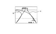
本発明の実施例で用いる第1の光源2及び第2の光源3の発光色としては、可視光や赤外光を用いればよい。もし、自動車に搭載できる光源の波長に規制がある場合は、ウィンドウガラス4の透過率のよい波長の中から特定波長を選択すればよい。例えば、図5(a)に示すウィンドウガラス4の透過率32が所定値(図5(a)では70%)以上で撮像素子30の感度31も高い波長(波長fa以下。具体的には400〜600nmの中の可視光領域の波長)を選べば良い。あるいは、対向車や歩行者を眩惑しないようにするためには、可視光より波長が長くて撮像素子30の受光感度31がおよぶ範囲の波長fb(例えば800〜1000nmの中の赤外光領域の波長)を選べば良い。このようにして選択した第1の光源2及び第2の光源3の波長に対応して光学フィルタ20の特性を選択すれば良い。すなわち、後者の赤外光領域の波長を持つ光源を選択した場合は、可視領域の波長をカットし、可視領域より長波長側で撮像素子が感度を有する波長域の光を透過するような特性の光学フィルタを用いればよい。
Visible light or infrared light may be used as the emission color of the first
光学フィルタ20の構成例を図6に示す。図6(a)は、撮像素子30の光が入射する側の面を、特定波長を透過するバンドパスフィルタ21で覆った例である。これは、雨滴、曇りのみを検知する場合の例で、特定波長の光を光源2あるいは光源3より照射して、その波長の光のみを受光できるので、外光の影響を受けることがない。図6(b)は、図6(a)と同じ側の片面でも、一部領域のみをバンドパスフィルタ21で覆った例である。図6(a)は撮像素子30で特定波長の光しか受光できないが、図6(b)は特定波長だけでなく、その他の波長の光も受光できるため、ウィンドウガラス4を通して車外の画像を撮像して処理することができる。更に、ウィンドウガラス4の赤外光透過率が大きい場合は、外光である太陽光による影響を軽減するため、図6(c)に示すように図6(a),図6(b)のバンドパスフィルタ21の光入射側に赤外光カットフィルタ22を配置してもよい。また、図6(d)のように1つの光学フィルタ20に赤外光カットフィルタとバンドパスフィルタの領域を持つようにしても良い。ここで、赤外光カットフィルタとバンドパスフィルタ(波長fc)の透過率の例を図5(b)に示す。バンドパスフィルタとしては、例えば中心透過波長fcが850nmで、透過率が半分になる波長の幅すなわち半値幅が±20nmの波長を通すものを用いることができる。
A configuration example of the
図6(d)に示したように、撮像素子30の一部領域に赤外光カットフィルタを通った光を入射させ、他の領域にバンドパスフィルタを通った光を入射させるようにすると、ウィンドウガラス4に付着した雨滴や曇りの検知だけでなく、車両や車線など他の物体の検知を行うことが可能であり、その実施例を図7に示す。本実施例は、ヘッドライトの配向制御機能と雨滴検知機能を一台の撮像装置で同時に成立させる場合を示す。 図7(a)に示すように、車載用画像処理装置は車両前方に設置され、フロントガラス越しに前方の景色を撮影し、撮像素子30によって図7(b)のような画像を取り込む。配光制御機能は図7(b)の画像から画像処理を行い、図7(c)のように先行車210のテールライト230及び対向車220のヘッドライト240を抽出する。そして図7(c)の画像から先行車及び対向車の位置を計測し、先行車及び対向車の位置に応じて自車のヘッドライトの配向を制御する機能である。なお、250は地平線である。
As shown in FIG. 6D, when light that has passed through the infrared light cut filter is incident on a part of the
従って、図7(b)のように、遠方の車両のヘッドライト及びテールライト、近傍の車両のヘッドライト及びテールライトが映る撮影範囲が配向制御機能を実現する上で必要な画像処理範囲となる。ここで、先行車を認識する際に、先行車のテールライトで先行車の有無を判断する必要があるが、対向車のヘッドライトと比べて光量が小さく、また街灯など外乱となる光が多数存在するため、輝度のみからテールライトを検出するのは困難であり、テールライトの赤色を認識する必要がある。 Therefore, as shown in FIG. 7B, the imaging range in which the headlights and taillights of a distant vehicle and the headlights and taillights of a nearby vehicle are reflected is an image processing range necessary for realizing the orientation control function. . Here, when recognizing a preceding vehicle, it is necessary to determine the presence or absence of a preceding vehicle with the taillight of the preceding vehicle, but the amount of light is small compared to the headlight of the oncoming vehicle, and there are many disturbing lights such as street lights Therefore, it is difficult to detect the taillight only from the luminance, and it is necessary to recognize the red color of the taillight.
しかしながら、赤色を認識するために撮像素子30としてカラー撮像素子を用いる場合、カラー撮像素子は赤外領域にも感度を持つので、単に撮像素子のみで画像を取り込んだ場合、得られる画像データは全体的に赤くなってしまい、テールライトの赤色を示す部分を抽出することが困難である。そこで、例えば図8のような赤外光をカットする特性をもつフィルタを、図7(a)の光学フィルタ20の位置か、又はレンズ10の前方に設置することで、赤色とそれ以外の色の区別をすることが容易になる。これにより、外乱となる他の色の光を除去できるため、テールライトの検出精度を向上させることができる。ここで、図8のような赤外光をカットする特性を持つフィルタはカットする波長xや透過率の低下の仕方などは、それぞれの用途や撮像素子の性能、図5に示すウィンドウガラス4の透過率などに適した特性のものを選択する。典型的には、図8の波長xは約600nmとすればよい。
However, when a color image sensor is used as the
以下では、光源2の波長として赤外波長、例えば850nmとする。赤外波長の光を照射する光源2は、例えば発光ダイオード(LED)や半導体レーザなど種々のものが利用可能である。ここで赤外波長の光を照射する光源2は、例えば図9(a)に示すように、ウィンドウガラス4に付着した雨滴8で反射した光が撮像素子30に入射する角度に設置し、フロントガラス4に向けて出射する赤外波長の光43は放射状の光でも平行光でも良い。
Hereinafter, the wavelength of the
ここで、水滴に反射した赤外波長の光をそのまま検出しようとすると、赤外波長の光を照射する光源2は、例えば太陽光など膨大な光量を持つ外乱光よりも照射する光を明るくしなければならないという問題がある。
Here, if it is going to detect the light of the infrared wavelength reflected in the water droplet as it is, the
そこで、例えば図9(b)に示すように、光源2の発光波長よりも短い波長の光をカットするようなフィルタか、もしくは図9(c)のような、透過率のピークを光源2の発光波長とほぼ一致させたバンドパスフィルタを、図9(a)における光学フィルタ20の位置かレンズ10の前方に設置する。これにより、必要となる光源2の発光波長以外の光を除去し、検出される光源2の光量を相対的に大きくできる。ここで図9(b)でカットする波長yや透過率の低下の仕方、また、図9(c)でバンドパスフィルタの透過率ピーク波長zや透過率,半値幅などの特性はそれぞれの用途や撮像装置の性能などに適したものを選択すればよい。このようなフィルタを用いて撮像素子30で撮影した雨滴の画像の例を図9(d)に示す。
Therefore, for example, as shown in FIG. 9B, a filter that cuts light having a wavelength shorter than the emission wavelength of the
図10は、領域によって光学特性を異ならせたフィルタ例を示す図である。例えば画面上部2/3で配光制御を、画面下部1/3で雨滴検知を行うように画像処理を行う領域に分け、これら二つの機能を同時に成り立たせるために、一枚のフィルタに赤外カット特性を持つ領域(以下、「赤外カット領域」と称する)51aと赤外領域に透過率のピークを有するバンドパス特性を持つ領域(以下、「赤外バンドパス領域」と称する)52aを分けて作成する。例えば図10(a)のような構成である。このようなフィルタを一枚使うことで、従来は機能の数だけ必要であった撮像部が一つで済むようになり、大幅な小型化,コスト低減が可能となる。 FIG. 10 is a diagram illustrating an example of a filter having different optical characteristics depending on regions. For example, the light distribution control is performed at the top 2/3 of the screen and the image processing is performed so that raindrop detection is performed at the bottom 1/3 of the screen. A region having a cut characteristic (hereinafter referred to as “infrared cut region”) 51a and a region having a band pass characteristic having a transmittance peak in the infrared region (hereinafter referred to as “infrared band pass region”) 52a. Create separately. For example, the configuration is as shown in FIG. By using one such filter, only one imaging unit, which has conventionally been required for the number of functions, can be used, and a significant reduction in size and cost can be achieved.
また、フィルタを一枚にすることで、フィルタ間の反射が低減され、画像処理に不利となる外乱光を減らすことができる。また、機械的な可動部が無くなり、フィルタが固定となるため、画像を取り込む速度が高速になっても複数の映像を連続時間的に撮り込むことが可能となる。 Further, by using one filter, reflection between filters is reduced, and disturbance light that is disadvantageous for image processing can be reduced. In addition, since there is no mechanical moving part and the filter is fixed, it is possible to capture a plurality of videos continuously even if the speed of capturing an image is increased.
ここで、フィルタの領域の分け方は図10(b)〜(d)に示すように、様々な方法を取ることができる。しかしながら図7に示すように、対向車のヘッドライト及び先行車のテールライトは、主として画面上部に写ることが多く、画面下部には自車近傍の路面が写るのが通常であるから、配光制御においては画面上部の情報が重要であり、画面下部の情報はあまり重要でない。よって、配光制御機能と雨滴検知機能を両立させる場合には、上記のように画面下部を雨滴検知用の赤外バンドパス領域とし、残りの領域を配光制御用の赤外カット領域とする図10(a)の構成が好適である。 Here, as shown in FIGS. 10B to 10D, various methods can be used for dividing the filter area. However, as shown in FIG. 7, the headlight of the oncoming vehicle and the taillight of the preceding vehicle are often reflected mainly at the top of the screen, and the road surface near the vehicle is usually reflected at the bottom of the screen. In control, information at the top of the screen is important, and information at the bottom of the screen is not very important. Therefore, in order to achieve both the light distribution control function and the raindrop detection function, the lower part of the screen is used as an infrared bandpass region for raindrop detection as described above, and the remaining region is used as an infrared cut region for light distribution control. The configuration shown in FIG. 10A is preferable.
図10(a)に示す光学フィルタ20を有する撮像装置を図11に示す。また光学フィルタ20を図11に示すような撮像装置に取り付けた場合に取得される映像を図12に示す。ここでレンズ10の特性により、撮像対象となる実際の光景と撮像素子30に集光された映像とでは天地が逆になる。そこで、画面下部を雨滴検知用の赤外バンドパス領域とするためには、光学フィルタ20の天側を赤外バンドパス領域52aとする。この撮像装置を用いて撮影した車両と雨滴の画像の例を図12に示す。
FIG. 11 shows an imaging apparatus having the
撮像部を上記のような構成とし、画像処理部において、赤外バンドパス領域を透過した光が集光する画像(以下、「撮像素子上の赤外バンドパス領域」と称する)を用いて雨滴検知を行い、赤外カット領域を透過した光が集光する画像(以下、「撮像素子上の赤外カット領域」と称する)を用いて配光制御を行うことで、一枚のフィルタで、機械的可動部を設けることなく、雨滴検知機能と配光制御機能の両立を実現する事が出来る。 The image pickup unit is configured as described above, and the image processing unit uses the image (hereinafter referred to as “infrared band pass region on the image pickup device”) where light transmitted through the infrared band pass region is collected as raindrops. By performing light distribution control using an image (hereinafter referred to as “infrared cut area on the imaging device”) where light that has passed through the infrared cut area is collected by detection, with a single filter, A raindrop detection function and a light distribution control function can both be achieved without providing a mechanical movable part.
ここで撮像部は、図11に示すように、光学フィルタ20と撮像素子30との間に空隙がある構成としてもよいが、光学フィルタ20を撮像素子30に密着させる構成とした方が、光学フィルタ20上の領域の境界と、撮像素子30上の領域の境界を一致させやすくなる。
Here, as shown in FIG. 11, the imaging unit may have a configuration in which there is a gap between the
なお、撮像素子30上の赤外カット領域及び赤外バンドパス領域は、撮像素子30の画素の番号によって定めることが出来る。すなわち、図10(a)の例であれば、撮像素子30の上端から例えばN画素目までを赤外バンドパス領域とし、撮像素子30の下端から例えばM画素目までを赤外カット領域とすることも出来る。
The infrared cut region and the infrared band pass region on the
また、赤外光バンドパス領域を透過して撮像素子30に入射する光の光量は、赤外カット領域を透過して入射する光の光量よりも小さい。このため、走行環境,光線状態によっては、撮像装置のシャッタ速度を赤外カット領域の撮像素子30が飽和しないようなシャッタ速度に設定すると、赤外光バンドパス領域の画像は露光不足により暗くなるため、自車近傍にいる車両のテールライトやヘッドライトが見えなくなる場合もある。そこで、図13(a)に示すように、撮像部と画像処理部からなる画像処理装置1を水平方向から前傾させることで、図13(b)に示すように遠方の車両のテールライト及びヘッドライト,近傍の車両のテールライト及びヘッドライトが、赤外カット領域に写るようになり、配光制御機能を成立させることができる。ここで、前傾させる角度は車両の高さ,レンズ10及び撮像素子30の大きさ及び配置等に依存するが7°程度が好適である。また、撮像部だけを前傾させる構成としても良く、あるいはレンズの画角を下側に拡大し、撮影範囲を広げる構成としても同様の効果が得られる。
In addition, the amount of light that passes through the infrared bandpass region and enters the
他の実施例として、車線検知機能と雨滴検知機能を同時に成立させる場合について説明する。まず雨滴検知機能を実現するためには、既に述べたように、図10(a)に示すようにフィルタの上部を赤外バンドパス領域とすればよい。 As another embodiment, a case where the lane detection function and the raindrop detection function are simultaneously established will be described. First, in order to realize the raindrop detection function, as described above, the upper part of the filter may be an infrared bandpass region as shown in FIG.
一方、車線検知機能を実現するためには自車近傍の車線を検出することが特に重要である。なぜなら図14に示すように、車線は、直線81だけでなくカーブ82があるため、遠方になるほど画面内での車線の移動量が大きくなるが、逆に自車近傍の車線は車線内を走行しているときには画面内での移動量が小さいという特徴があるからである。
On the other hand, in order to realize the lane detection function, it is particularly important to detect a lane in the vicinity of the own vehicle. Because, as shown in FIG. 14, the lane has not only the
よって、上記のようにフィルタの上部を赤外バンドパス領域とすると、車線検出機能で特に重要となる自車近傍の画像情報は画面の下側に写るので、フィルタの上部すなわち赤外バンドパス領域を透過して撮像素子30に入射することになるが、車線の画像情報は可視光領域の波長であるため、上記のバンドパス特性によって減衰されて透過光量が低くなり、特に夜間の車線検出が困難になる。 Therefore, if the upper part of the filter is the infrared bandpass region as described above, the image information in the vicinity of the host vehicle, which is particularly important for the lane detection function, appears on the lower side of the screen. However, since the image information of the lane is the wavelength in the visible light region, it is attenuated by the above bandpass characteristic and the amount of transmitted light is reduced. It becomes difficult.
上記に加えて、車線形状からカーブも検知しようとすると、自車近傍のみならず遠方の車線も検知する必要があるため、車線検出においては遠方の画像も不要な情報ではなく、赤外バンドパス領域をフィルタの下部に設置して、この領域を用いて雨滴検知を行うことも望ましくない。 In addition to the above, when trying to detect a curve from the lane shape, it is necessary to detect not only the vicinity of the host vehicle but also a distant lane. It is also undesirable to install an area below the filter and use this area to detect raindrops.
そこで、図13(a)に示すように画像処理装置1を例えば7°前傾させると、図13(c)に示すように、遠方から自車近傍までの車線全てを、赤外バンドパス領域外に映すことができ、雨滴検知機能と車線検知機能を同時に実現することが可能となる。ここで、傾けるのは撮像部のみでもよい。また、画角の広いレンズを用いて撮影範囲を広げることでも、雨滴検知に必要な領域を確保しつつ、遠方から自車近傍までを映すことが可能となる。
Therefore, when the
通常、カメラを下に傾けていくと自車のボンネットが映りこみ、自車のボンネットで反射した太陽光や先行車のテールライトなどが外乱となり、車線検知や配光制御を行う上で不利な条件となる。しかし、例えば図10(a)のようなフィルタを用いるとバンドパスの特性により、外乱光を除去し、かつその領域を雨滴検知用の画像処理を行う領域に割り当てることができる。前記フィルタを用いることでこれまで画像処理には不向きとされていた領域での画像処理が可能となる。また、バンドパスの透過率と同じ発光波長である赤外光源を備え、照射することで、道路上にある障害物を検知したり、先行車の位置を特定したりすることも可能となる。 Normally, when the camera is tilted down, the hood of the vehicle appears, and sunlight reflected by the hood of the vehicle and the taillight of the preceding vehicle become disturbances, which is disadvantageous for lane detection and light distribution control. It becomes a condition. However, for example, when a filter as shown in FIG. 10A is used, disturbance light can be removed and the area can be assigned to an area where image processing for raindrop detection is performed due to the characteristics of the bandpass. By using the filter, it is possible to perform image processing in an area that has been unsuitable for image processing. In addition, an infrared light source having the same emission wavelength as the bandpass transmittance is provided, and by irradiating it, it is possible to detect an obstacle on the road and to specify the position of the preceding vehicle.
なお、これらの実施例では、最良の構成としてレンズ10と撮像素子30との間にフィルタを設ける構成を用いて説明したが、レンズ又はレンズの前面に取り付けられるレンズカバーを上記のフィルタと同様の光学特性を有する構成としても、同様の効果が得られる。
In these embodiments, the best configuration has been described using a configuration in which a filter is provided between the
図15を参照して、本発明の画像処理システムを用いて、ウィンドウガラス4の外側に付着した雨滴とウィンドウガラス4の内側に付着した曇りを検出する方法について述べる。図15(a)は光源2及び光源3の発光回路構成例を示す図、図15(b)は発光タイミング、雨滴と曇り検出タイミングの例を画像の垂直同期信号に同期して示した図である。光源2を発光するには、画像処理装置1がトランジスタ9−1のベース電圧を制御することで光源2に所定の電流を流し、また、光源3を発光するには、トランジスタ9−2のベース電圧を制御することで光源3に所定の電流を流す。まず、ウィンドウガラス4の外側に付着した雨滴を検出する場合は、画像処理装置1が第1の光源2を発光させて、ウィンドウガラス4を照射する。ウィンドウガラス4の外側に雨滴が付着している場合は、雨滴によって第1の光源2が発した光が散乱して一部が反射光として撮像素子30に入射する。撮像素子30は入射光を画像として画像信号を生成する。その画像信号を画像処理プロセッサ(図示していない)に入力する。そして、その画像信号を画像処理プロセッサで処理することで、ウィンドウガラス4の外側に付着した雨滴を検出することができる。ここでは画像処理プロセッサを画像処理装置1の中に配置しているが、画像処理装置1とは別の装置として配置してもよい。
With reference to FIG. 15, a method for detecting raindrops adhering to the outside of the window glass 4 and fogging adhering to the inside of the window glass 4 using the image processing system of the present invention will be described. FIG. 15A is a diagram showing a light emitting circuit configuration example of the
画像処理プロセッサによる雨滴検出プログラムのフローの一例を図16に示す。図16(a)の処理では画像処理プロセッサは、ステップ1において、撮像素子30から光源2を点灯したときの画像信号を入力する。そして画像信号に対して、ステップ2で、例えば公知であるラプラシアンフィルタを用いてエッジ検出処理を行う。このエッジ検出処理により雨滴の領域と、雨滴でない領域の境界を強調した画像を作成することができる。
An example of the flow of the raindrop detection program by the image processor is shown in FIG. In the process of FIG. 16A, the image processor inputs an image signal when the
次に、ステップ2で作成したエッジ画像に対して、ステップ3で円検出処理を実行する。円検出処理としては公知である一般化ハフ変換を行えばよい。ステップ3で円検出を行った後で、ステップ4で検出した円の個数を数える。次に、ステップ5で円の個数を雨量に変換して、雨量を求めて処理を終了する。
Next, a circle detection process is executed in
ウィンドウガラス4の外側表面に撥水処理を施しておけば、雨滴が円形となるので処理に好都合である。また、レンズ10の焦点をウィンドウガラス4の位置でなく、遠方にフォーカスするようにしておけば、雨滴はぼやけて、より円形として撮像することができるため、より雨滴を検出しやすくできる。雨滴を円形として個々に区別できれば、所定時間毎の雨量を画像処理装置1で計算できる。
If the water repellent treatment is performed on the outer surface of the window glass 4, raindrops become circular, which is convenient for the treatment. Further, if the focal point of the
また、他の処理例として図16(b)に示す方法が考えられる。図16(b)では、画像処理プロセッサは、ステップ21で光源2を点灯したときと消灯したときの画像信号を撮像素子30から入力する。そしてそれらの画像信号に対して、ステップ22で、輝度差を計算する。次に、ステップ22で作成した輝度差に対して例えば平均値を求めて、ステップ23で予め定めた閾値と大小判定処理を実行する。もし、輝度差が閾値より大きい場合は、ステップ24で雨、汚れを検出したと判定し、ステップ22で作成した輝度差からステップ25で雨量に変換して、処理を終了する。もし、輝度差が閾値より小さい場合は、処理を終了する。この方法によれば、例えば霧雨のように雨滴が円形として撮像できない場合でも、雨量を検出することができる。
Further, as another processing example, a method shown in FIG. In FIG. 16B, the image processor inputs image signals when the
図16(a)、(b)の処理は独立に用いても良いし、組合せて用いても良い。組合せることで、より精度良く雨量を計測することができる。画像処理装置1内の記憶部に、図16(a)、(b)に示す処理フローのプログラムを記憶しておけばよい。
The processes of FIGS. 16A and 16B may be used independently or in combination. By combining, it is possible to measure the rainfall with higher accuracy. A program for the processing flow shown in FIGS. 16A and 16B may be stored in the storage unit in the
画像処理装置1は、図16(a)、(b)により計算した雨量に基づいて、ワイパーあるいはウォッシャーを制御することができる。ワイパー、ウォッシャーの制御構成例を図17に示す。図17は、ワイパー/ウォッシャー制御部100、ワイパー160、ワイパー160を動かすモータ150及びウォッシャー制御部170で構成される。
The
ワイパー/ウォッシャー制御部100でワイパー160を制御する処理フローの例を図18に示す。図18では、まずステップ100でシフトレバーの位置がパーキングレンジ(Pレンジ)に入っているかどうかを判定し、Pレンジに入っていれば、ワイパー160の動作を禁止する(ステップ101)。これにより、洗車時のワイパー160の誤動作を防止できる。Pレンジに入っていない場合は、ステップ110に進んでワイパー160を起動する。
An example of a processing flow for controlling the
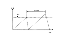
ステップ110でワイパー160を起動する方法の例を図19に示す。図19では、横軸に時間、縦軸に雨量をとり、雨量が閾値を超えたときワイパー160を起動する。ステップ111で車速Vが0かどうかを判定し、V=0ならステップ112でワイパー160を起動する雨量判定閾値を大きくする。ステップ116で待ち時間を所定値とする。ステップ111で判定した車速が0でない場合は、雨量判定閾値を所定値かあるいは車速に応じて変更する。ステップ113では車速に応じて閾値を変更する。そして、ワイパー160を起動した後、次にワイパー160を起動するまでの待ち時間を計算する。ステップ114では車速Vに反比例した待ち時間としている(kは比例係数)。車速Vだけでなく、雨量や雨の粒径に応じて下式のように決めてもよい。ここで、k1,k2,k3は比例係数である。
待ち時間=k1/雨量+k2*粒径+k3/車速
An example of a method for starting the
Waiting time = k1 / rainfall + k2 * particle size + k3 / vehicle speed
この待ち時間により、ワイパーブレードが雨滴を払拭したことにより生じる雨の膜や雨に筋等を検出してすぐにワイパー160を起動しないようにすることができる。次に、ステップ115で待ち時間だけ待ち、ステップ102で雨量とワイパー160を起動する閾値とを比較する。雨量が閾値より大きい場合は、ステップ103でワイパー160を起動して、処理を終了する。雨量が閾値より小さい場合は、処理を終了する。
By this waiting time, it is possible to prevent the
また、他のワイパー起動方法の例を図20に示す。図20に示したステップ120は、図18のステップ110の代わりに用いることができるもので、ワイパー制御として用いられている間欠時間(インターバル)を制御するものである。図20において、k4,k5,k6は比例係数である。例えば、計測した雨量、雨の粒径を用い、インターバルを制御する。雨量が多いときや粒径が小さいときはインターバルを短くし、逆に雨量が少ないときや粒径が大きいときはインターバルを長くすればよい。このとき、自車の走行速度Vに応じてインターバルを変更してもよい。例えば、走行速度が早い場合は雨滴が風速によりウィンドウガラス4上を流れていくので、インターバルを長めにしてもよい。
An example of another wiper activation method is shown in FIG. Step 120 shown in FIG. 20 can be used in place of
雨滴の実施例では粒径を計測しているが、これはウィンドウガラス4の撥水性がよいほど雨滴が円形に近くなり、粒径の計測しやすくなる。このウィンドウガラス4の撥水性の程度を、図16で入力した画像から、雨滴の形状、反射輝度等を用いて判定することができる。また、ワイパー160を起動した後の画像を入力して、拭き残しの雨滴の量や形状(筋状の雨滴)などを検出すれば、ワイパー160のブレードの傷みを検出することもできる。これら検出した撥水性の程度やブレードの傷みは、図17のモータ150に流れる電流を検出して、モータ150のトルクを推定し、このトルクが大きくなったら撥水性が悪くなった、あるいはブレードの傷みが生じたと判定することもできる。そして、これら検出した撥水性の程度やブレードの傷みをドライバーに警報することで、常に良好な視界を確保することが可能となる。
In the embodiment of raindrops, the particle size is measured. However, the better the water repellency of the window glass 4, the closer the raindrop is to a circle, and the easier it is to measure the particle size. The degree of water repellency of the window glass 4 can be determined from the image input in FIG. 16 using the shape of raindrops, reflection luminance, and the like. Further, if the image after the
図16(b)で説明したステップ24で検出した雨や汚れでワイパー160を起動した後、同じに位置に更に検出した場合は、汚れがウィンドウガラス4に付着していると判定し、ウォッシャー制御部170を制御して水をウィンドウガラス4にかける制御を行ってもよい。
If the
また、画像処理装置1がワイパー160の払拭周期(待ち時間やインターバル時間)を制御できるので、ワイパー160の払拭周期に応じて画像処理装置1が撮像素子30から画像を取得する周期を変更可能となり、雨量が少ない場合は長い周期で雨滴の検出処理を実行し、雨量が激しい場合は短い周期で雨滴の検出処理を実行することができ、画像処理の効率が向上する。
In addition, since the
更に、図16で入力した画像を基に街灯や車のライトによる外界の明るさを計測し、その明るさによりワイパー160の払拭周期を変えてもよい。例えば、明るいときに払拭周期を早くし、暗いときに遅くする。これにより、霧雨のような場合、街灯や車のライトが雨滴で散乱して、視界が不良になるのを抑えることができる。
Furthermore, the brightness of the outside world by a street light or a car light may be measured based on the image input in FIG. 16, and the wiping cycle of the
また、計算した雨量に基づいて、フォグランプの点灯/消灯あるいはハイビームの禁止/許可を制御することもできる。例えば、図21に示すように、雨量が多いときはフォグランプを自動点灯し、ハイビームを禁止すればよい。図21では、雨量が多いときにフォグランプが点灯していない場合は自動点灯するかあるいは点灯を促す警報をドライバーに出力し、フォグランプが点灯している場合はなにもしない。そして、ハイビームが点灯していなければ点灯禁止し、ハイビームが点灯している場合は自動消灯するかあるいは消灯を促す警報をドライバーに出力する。また、雨量が少ないときはフォグランプの点灯、消灯の制御は行わず、ハイビームについては先行車あるいは対向車の位置(距離、方向)に応じて自動点灯、自動消灯の制御を行う。これにより、雨でヘッドライトの光が散乱するのを抑えることができ、視界を良好にすることができる。 Further, it is possible to control whether the fog lamp is turned on / off or the high beam is prohibited / permitted based on the calculated rainfall. For example, as shown in FIG. 21, when there is a lot of rain, the fog lamp may be automatically turned on to prohibit the high beam. In FIG. 21, when the fog lamp is not lit when there is a lot of rain, it automatically turns on or outputs an alarm prompting the lighting to the driver, and nothing is done when the fog lamp is lit. If the high beam is not lit, lighting is prohibited. If the high beam is lit, an automatic turn-off or a warning prompting the turn-off is output to the driver. Also, when the rainfall is low, the fog lamp is not turned on / off, and the high beam is automatically turned on / off according to the position (distance, direction) of the preceding vehicle or oncoming vehicle. Thereby, it can suppress that the light of a headlight is scattered by rain, and can improve a visual field.
次に、室内気温と外気温との差によってウィンドウガラス4の内側に付着した曇りを検出する場合は、画像処理装置1が第2の光源3を発光させて、ウィンドウガラス4を照射する。ウィンドウガラス4の内側に曇りがない場合は、ウィンドウガラス4の内側で第2の光源3からの光が全反射して撮像素子30に入射する。ウィンドウガラス4の内側に曇りがある場合は、曇りによって第2の光源3からの光が散乱して一部が反射光として撮像素子30に入射する。画像処理装置1内の記憶素子には、予めウィンドウガラス4の内側に曇りがないときの反射光の最大明るさを初期値として記憶しておく。そして、撮像素子30からの画像信号を入力し、画像の最大明るさを求め、記憶していた初期値との差分を画像処理プロセッサによって計算する。画像処理プロセッサによって計算された差分が大きい場合は、ウィンドウガラス4の内側に曇りが発生したと判定する。
Next, when detecting cloudiness adhered to the inside of the window glass 4 due to the difference between the room temperature and the outside temperature, the
図22に、曇り検出処理の一例のフローを示す。画像処理プロセッサは、ステップ11で第2の光源3を点灯してウィンドウガラス4を照明し、撮像素子30から画像信号を入力する。そしてステップ12で、画像信号からウィンドウガラス4の内側で反射した光の最大明るさを検出する。ステップ13で、検出した明るさと記憶素子に記憶した初期値との差分を算出する。ステップ14で、差分を曇り程度に変換することで、曇りが検出され、図22のフローを終了する。画像処理装置1がウィンドウガラス4の内側に付着した曇りを検出した場合、画像処理装置1とエアコンディショナを連動させて、曇りを除去するために、自動車の室内の通風系,温度,風量等を制御する。
FIG. 22 shows a flow of an example of the fog detection process. In
次に、本発明の他の実施例について説明する。画像処理システムにおいて、画像処理装置1が取得した画像を処理して外光の明るさを計測し、計測した外光の明るさに基づいて、例えば昼夜を判別して第1の光源2と第2の光源3が照射する位置を変更するように、第1の光源2と第2の光源3を画像処理装置1によって制御してもよい。
Next, another embodiment of the present invention will be described. In the image processing system, the image acquired by the
具体的に図23及び図24に示した模式図を用いて説明する。本実施例では、第1の光源2と第2の光源3を複数個の発光素子で構成する。図23及び図24の例では、2個の第1の光源2−1,2−2と2個の第2の光源3−1,3−2を用いる。
This will be specifically described with reference to schematic diagrams shown in FIGS. In this embodiment, the first
例えば、昼間であれば太陽光を含んだ周辺光が撮像素子30に入射されるため、第1の光源及び第2の光源が消灯しているタイミングで画像を撮像すると明るい画像が得られる。従って、撮像素子30で撮影した画像の明るさを画像処理プロセッサで解析すれば、昼夜を判別することができる。撮像素子30は前方を向いているので、自車両が走行する道路面も画像中に含まれる。もし昼間であれば、撮像素子30で撮影した画像の中で、道路面は暗い領域となる。そこで、撮像素子30が撮影した画像が暗い領域を含んでいれば、暗い領域を照射するように光源を選択してもよい。光源2−2は、撮像素子30のほぼ中心位置に配置された光源2−1よりもわずかに下方に設置され、画像の道路面付近のウィンドウガラス4を照射できるようにしてある。また光源3−2は、光源3−1よりもウィンドウガラス4側に配置され、画像の道路面付近のウィンドウガラス4を照射できるようにしてある。もし昼間であれば、図24に示した駆動回路において、光源2−2あるいは光源3−2が発光するようにトランジスタ9−3あるいはトランジスタ9−4のベース電圧を制御することで、光源2−2あるいは光源3−2に所定の電流を流すようにする。そうでなければ、光源2−1あるいは光源3−1が発光するようにトランジスタ9−1あるいはトランジスタ9−2のベース電圧を制御することで光源2−1あるいは光源3−1に所定の電流を流すようにする。この結果、太陽光など明るい周辺光の影響を少なくして、雨滴や曇りを検出することができる。
For example, since ambient light including sunlight enters the
また、画像処理装置1が取得した画像を処理して外光の明るさを計測し、計測した外光の明るさに基づいて、第1の光源2と第2の光源3が照射する光の強さを変更する画像処理システムの制御方法も考えられる。自動車周辺の外光の強さは、上述した昼夜判定と同様に画像の明るさにより判別できる。そして、外光が明るい場合は光源の発光の強さを強くし、外光が暗い場合は光源の発光の強さを弱くする。本制御方式も図24の構成を用いて行うことができる。例えば、トランジスタ9−1,9−2,9−3,9−4のベース電圧を画像処理プロセッサによって制御することで、光源2−1,2−2,3−1,3−2に流す電流を制御でき、光源2−1,2−2,3−1,3−2の発光の強さを変更することができる。本制御方式を用いた画像処理システムによれば、昼間でも外光の影響を受けることなく雨滴,曇りを検出することができる。また、光源2−1,2−2,3−1,3−2に赤外光を用いる場合、夜は他車両や歩行者に幻惑を与えることなく雨滴,曇りを検出することができる。
In addition, the brightness of the external light is measured by processing the image acquired by the
また、本発明の他の実施例では、図25(a)に示すように、第2の光源3をアレイ状に配列した複数の光源によって構成する。図25(a)に示す例では、4つの光源3−11,3−12,3−13,3−14で第2の光源3を構成している。図25(c)にはアレイ状に配列した複数の光源の点灯回路構成例を示す。図25(c)の回路では4つの光源3−11,3−12,3−13,3−14は同時に点灯するように制御される。あるいは、図25(d)に示す複数のトランジスタ9−21〜9−24を用いて光源を点灯するようにしても良い。図25(d)の回路によれば、4つの光源3−11,3−12,3−13,3−14は1個ずつ順番に点灯するように制御される。本実施例の光源を用いれば、ウィンドウガラス4における曇りの程度だけでなく、曇りの進行方向や曇り進行速度をも画像処理プロセッサなどを用いて計測することができる。
Further, in another embodiment of the present invention, as shown in FIG. 25A, the second
例えば、図25(b)に示すようにウィンドウガラス4の内側上部に曇りが発生した場合を考えると、ウィンドウガラス4からの反射光の明るさが、光源3−11からの反射光が最初に暗くなり、次に光源3−12からの反射光が暗くなり、続いて光源3−13,光源3−14の順に反射光が暗くなっていったとすると、それはウィンドウガラス4の内側の曇りが光源3−11から光源3−14の方向に進行していることを表している。ウィンドウガラス4からの反射光が、光源3−14から光源3−11の順に暗くなっていけば、ウィンドウガラス4の内側の曇りの進行方向は、上記例とは逆方向となる。 For example, as shown in FIG. 25 (b), when the fog occurs on the inner upper part of the window glass 4, the brightness of the reflected light from the window glass 4 is the same as the reflected light from the light source 3-11 first. If the reflected light from the light source 3-12 becomes darker and then the reflected light becomes darker in the order of the light source 3-13 and then the light source 3-14, the fogging inside the window glass 4 is the light source. It represents that the light travels from 3-11 to the light source 3-14. If the reflected light from the window glass 4 becomes darker in the order of the light source 3-14 to the light source 3-11, the traveling direction of fogging inside the window glass 4 becomes the opposite direction to the above example.
更に、光源3−11からの反射光が暗くなって、次に光源3−12からの反射光が暗くなるまでの時間間隔,光源3−12が暗くなって次に光源3−13が暗くなるまでの時間間隔を求めることで、ウィンドウガラス4の内側における曇りの進行速度を計算することができる。この場合は、光源3−11〜3−14の間隔も計算に用いるので、記憶素子に記憶しておく必要がある。本実施例によれば、ウィンドウガラス4の周辺から曇り領域が進展してきているのか、あるいは曇り領域が減少しているのかという情報とともに、その速度がわかるため、デフロスタからの風量をきめ細かく制御でき、ウィンドウガラス4の曇りを効率的に除去することができるようになる。 Further, the time interval until the reflected light from the light source 3-11 becomes dark and then the reflected light from the light source 3-12 becomes dark, the light source 3-12 becomes dark and then the light source 3-13 becomes dark. By calculating the time interval until, the traveling speed of fogging inside the window glass 4 can be calculated. In this case, since the interval between the light sources 3-11 to 3-14 is also used for the calculation, it must be stored in the storage element. According to the present embodiment, since the speed is known together with the information whether the cloudy area is developing from the periphery of the window glass 4 or whether the cloudy area is decreasing, the air volume from the defroster can be finely controlled, The fogging of the window glass 4 can be efficiently removed.
ウィンドウガラス4の内側に曇りを検出した場合、まず、エアコンを制御して曇りを除去した後、雨滴検出処理によって検出した雨量によりワイパーを制御するようにしてもよい。これにより、ウィンドウガラス4の曇りにより雨滴が検出しにくくなることを防止することができ、また、図16の雨滴検出処理結果の精度を向上することができる。 When cloudiness is detected inside the window glass 4, first, the air conditioner may be controlled to remove the cloudiness, and then the wiper may be controlled based on the amount of rain detected by the raindrop detection process. Thereby, it can prevent that it becomes difficult to detect a raindrop by the cloudiness of the window glass 4, and the precision of the raindrop detection process result of FIG. 16 can be improved.
本実施例の画像処理システムを用いれば、ウィンドウガラス4の雨滴や曇りを精度良く検出でき、ワイパーやデフロスタをきめ細かく制御できるので、運転手にとって前方の視界が良好になって車線や前方車を検出しやすくなる。そのため、検出した車線や前方車の情報に基づいて、自車両の制御内容を変更することができる。 By using the image processing system of this embodiment, it is possible to accurately detect raindrops and cloudiness on the window glass 4 and to finely control the wiper and the defroster, so that the driver has better visibility and detects lanes and vehicles ahead. It becomes easy to do. Therefore, the control content of the host vehicle can be changed based on the detected lane information and information on the preceding vehicle.
また、本実施例の画像処理システムではレンズ10の焦点距離を遠方に固定していたが、ズームレンズ等を用いることで焦点距離を変化させ、ウィンドウガラス4の位置及び自動車よりも遠方に焦点を合わせて画像を取得するように構成してもよい。この構成の画像処理システムによれば、遠方と近傍で鮮明な画像を得ることができるため、遠方を走行する先行車のテールランプや対向車のヘッドランプの検出と、ウィンドウガラス4に付着した雨滴や曇りの検出を同一の画像処理システムで行うことができる。
Further, in the image processing system of the present embodiment, the focal length of the
ズームレンズ等により焦点距離を変化させるには時間が必要である。焦点距離が変化する時間を削減させるために、画像処理装置1に設けたレンズ10は、口径比が所定値以上(例えばF2.5以上)のレンズとしてもよい。本構成の画像処理システムによれば、遠方に焦点を合わせておいても、遠方と近傍の画像のボケを減らすことができるため、遠方を走行する先行車のヘッドランプや対向車のテールランプの検出と近傍のウィンドウガラス4に付着した雨滴や曇りの検出が容易にできる。
It takes time to change the focal length using a zoom lens or the like. In order to reduce the time required for changing the focal length, the
また、画像処理装置1が画像を処理して、雨滴や曇りを検出する際に、画像を処理する領域、即ち第1の光源2と第2の光源3が照射する領域に応じて雨滴や曇りを検出する閾値を変更するように構成してもよい。図1や図23に示すように、ウィンドウガラス4が傾斜している場合、撮像素子30によって取得した画像内の雨滴の大きさや反射光の強さが異なることが起こるため、このように検出閾値を変更することで良好に雨滴や曇りを検出することができる。
In addition, when the
更に、本発明の画像処理システムを搭載した自動車においては、画像処理システムのウィンドウガラスの異物検出結果を用いて、ワイパーやデフロスタを自動制御することもできる。さらに、本発明の画像処理システムを搭載した自動車においては、ウィンドウガラスの異物が除去できるため、前方の視界が良好になって車線や前方車を検出しやすくなり、ヘッドランプの配光制御,車間距離制御,車線逸脱警報など自車両の制御性が向上する。 Furthermore, in a vehicle equipped with the image processing system of the present invention, the wiper and the defroster can be automatically controlled using the foreign object detection result of the window glass of the image processing system. Further, in the automobile equipped with the image processing system of the present invention, the foreign matter on the window glass can be removed, so that the front visibility is improved and the lane and the front vehicle are easily detected. The controllability of the vehicle is improved, such as distance control and lane departure warning.
ウィンドウガラス4の領域のうち、第1の光源2及び第2の光源3、或いは何れか一方から照射された光の反射光を、撮像素子30で撮像する領域に、赤外波長の光を透過する特性を持たせるようにしてもよい。近年の自動車のウィンドウガラス4は、運転者の日射からの不快要素軽減のため、赤外カットコーティングされているものが多くなっている。この場合、第1の光源2及び第2の光源3からの赤外波長が吸収されてしまうため、充分な反射光が得られず、雨滴検出性能が低下してしまう。そのため図26に示すように、第1の光源2及び第2の光源3或いはその何れか一方から照射された光の反射光を撮像素子30で撮像する領域40に対して、赤外波長の光を透過するように、例えば赤外カットコーティングを塗布しない、或いは剥がすなどの処置を施すと、反射光を効率よく得られるようになり、雨滴検出性能を向上させることができる。
In the region of the window glass 4, the infrared light is transmitted to the region in which the reflected light of the light emitted from either the first
また、図27に示すように、ウィンドウガラス4の領域のうち、第2の光源3から照射された光の反射光を撮像素子30で撮像する領域50を、曇りが発生しやすくなるよう処理を施してもよい。例えば、その領域50の部分をすりガラスにする、或いは撥水コートを塗布するなどによって曇り易くすることにより、ウィンドウガラス4全面における曇りの発生をいち早く検出し、運転者の視界が妨げられる前にデフロスタを制御することができるようになる。
In addition, as shown in FIG. 27, the processing is performed so that the region 50 in which the reflected light of the light emitted from the second
画像処理装置1に設置するレンズ10の焦点は、無限遠とウィンドウガラス4の間としてもよい。前述したように、雨滴8を検出するためにはレンズ10の焦点がウィンドウガラス4の表面にある雨滴8に合っているよりもむしろ、多少ピンボケが発生したほうが円としての認識率が高くなり、雨滴検出性能が向上する。さらに、無限遠にレンズ10の焦点が合っていると、遠方を走行する先行車のテールランプを検出する時、特に撮像素子30がカラーで画素数の少ない補色フィルタで構成されている場合、撮像素子30上のテールランプの大きさが1〜4画素程度になると色再現ができずに赤と認識されない場合があり、正確な先行車のテールランプの検出が困難になる。レンズ10の焦点を無限遠よりも手前に合わせることにより、先行車のテールランプがボケて4画素以上の大きさになり、撮像素子30において正確に色が再現できる。これにより、雨滴検出と先行車のテールランプの検出を同時に満たすレンズ10の焦点を、固定することが可能になる。
The focal point of the
また、本発明によると、フロントガラスに付着した雨滴や曇りなどの異物を検出すると同時に、先行車のテールランプの検出に行うことが可能である。 Further, according to the present invention, it is possible to detect a foreign matter such as raindrops or cloudiness adhering to the windshield, and at the same time, to detect a tail lamp of a preceding vehicle.
本発明は、上記実施例で示した自動車だけでなく、鉄道車両、船舶、航空機等に用いられるガラス或いは一般建造物の窓ガラス等の各種のウィンドウガラスの表面に付着する雨滴等の液滴及び曇りや塵などの検知にも用いることができる。 The present invention is not limited to the automobile shown in the above embodiment, but also drops such as raindrops attached to the surface of various types of window glass such as glass used for railway vehicles, ships, aircraft, etc. or window glass of general buildings, and It can also be used to detect cloudiness and dust.
1…画像処理装置、2…第1の光源、3…第2の光源、4…ウィンドウガラス、5…ケース、6…ダッシュボード、7…熱伝導部材、8…雨滴、9−1〜9−4…トランジスタ、10…レンズ、11…通路、20…光学フィルタ、30…撮像素子、40…雨滴検知領域、50…曇り検知領域、210…先行車、220…対向車、51a,51b,51c,51d…赤外カット領域、52a,52b,52c,52d…赤外バンドパス領域、81…直線、82…カーブ、100…ワイパー/ウォッシャー制御部、150…モータ、160…ワイパー、170…ウォッシャー制御部
DESCRIPTION OF
Claims (37)
前記ガラスに付着した異物によって反射された前記第1の光源からの光を撮像する撮像素子と、
前記ガラスと前記撮像素子の間に設けられ前記反射光の特定波長を透過する光学フィルタと、
前記撮像素子で撮像した画像を処理する画像処理装置と、
を備え、
前記撮像素子の前方にレンズを有し、当該レンズの焦点は前記ガラスの位置よりも遠方に設定されていることを特徴とする画像処理システム。 A first light source that emits light toward the glass;
An image sensor that images light from the first light source reflected by the foreign matter attached to the glass;
An optical filter provided between the glass and the imaging device and transmitting a specific wavelength of the reflected light;
An image processing apparatus for processing an image captured by the image sensor;
With
An image processing system comprising a lens in front of the image sensor, wherein the focal point of the lens is set farther than the position of the glass.
前記第2の光源は、複数の発光体をアレイ状に配置されたものであって、
前記撮像素子は、前記ガラスに付着した曇りによって反射された前記第2の光源からの光を撮像し、
前記画像処理装置は、前記画像を処理して、前記曇りの前記ガラスへの付着程度、前記曇りの進行方向,前記曇りの前記ガラスへの付着速度の少なくとも一つを計測することを特徴とする画像処理システム。 The image processing system according to claim 4.
The second light source is a plurality of light emitters arranged in an array,
The imaging element images light from the second light source reflected by fogging attached to the glass,
The image processing device processes the image and measures at least one of the degree of adhesion of the fogging to the glass, the traveling direction of the fogging, and the adhesion speed of the fogging to the glass. Image processing system.
Priority Applications (5)
| Application Number | Priority Date | Filing Date | Title |
|---|---|---|---|
| JP2004106853A JP4326999B2 (en) | 2003-08-12 | 2004-03-31 | Image processing system |
| DE602004027198T DE602004027198D1 (en) | 2003-08-12 | 2004-08-12 | Image processing system |
| US10/916,444 US7208723B2 (en) | 2003-08-12 | 2004-08-12 | Image processing system which processes an image captured by an imaging device through a lens having a focus which is adjusted to a point beyond the glass |
| EP04019184A EP1507138B1 (en) | 2003-08-12 | 2004-08-12 | Image processing system |
| US11/474,337 US7247838B2 (en) | 2003-08-12 | 2006-06-26 | Rain/moisture and object imaging system for vehicle |
Applications Claiming Priority (3)
| Application Number | Priority Date | Filing Date | Title |
|---|---|---|---|
| JP2003207237 | 2003-08-12 | ||
| JP2003414076 | 2003-12-12 | ||
| JP2004106853A JP4326999B2 (en) | 2003-08-12 | 2004-03-31 | Image processing system |
Related Child Applications (1)
| Application Number | Title | Priority Date | Filing Date |
|---|---|---|---|
| JP2004180050A Division JP4327024B2 (en) | 2003-08-12 | 2004-06-17 | Image processing system |
Publications (3)
| Publication Number | Publication Date |
|---|---|
| JP2005195566A JP2005195566A (en) | 2005-07-21 |
| JP2005195566A5 JP2005195566A5 (en) | 2006-08-31 |
| JP4326999B2 true JP4326999B2 (en) | 2009-09-09 |
Family
ID=33568360
Family Applications (1)
| Application Number | Title | Priority Date | Filing Date |
|---|---|---|---|
| JP2004106853A Expired - Fee Related JP4326999B2 (en) | 2003-08-12 | 2004-03-31 | Image processing system |
Country Status (4)
| Country | Link |
|---|---|
| US (2) | US7208723B2 (en) |
| EP (1) | EP1507138B1 (en) |
| JP (1) | JP4326999B2 (en) |
| DE (1) | DE602004027198D1 (en) |
Cited By (6)
| Publication number | Priority date | Publication date | Assignee | Title |
|---|---|---|---|---|
| WO2013122242A1 (en) | 2012-02-13 | 2013-08-22 | Ricoh Company, Ltd. | Imaging unit and method for installing the same |
| WO2014010713A1 (en) | 2012-07-13 | 2014-01-16 | Ricoh Company, Ltd. | Imaging unit, attached matter detector, control system for vehicle, and vehicle |
| EP2770478A2 (en) | 2013-02-25 | 2014-08-27 | Ricoh Company, Ltd. | Image processing unit, imaging device, and vehicle control system and program |
| US9057683B2 (en) | 2011-11-02 | 2015-06-16 | Ricoh Company, Ltd. | Image pickup unit and vehicle in which image pickup unit is mounted |
| US9215427B2 (en) | 2012-02-13 | 2015-12-15 | Ricoh Company, Ltd. | Attached matter detector and in-vehicle device controller using the same |
| US9706177B2 (en) | 2011-11-29 | 2017-07-11 | Ricoh Company, Limited | Image processing system, vehicle including the same, image processing method, and computer program product |
Families Citing this family (83)
| Publication number | Priority date | Publication date | Assignee | Title |
|---|---|---|---|---|
| US8180099B2 (en) * | 2002-07-16 | 2012-05-15 | Trw Limited | Rain detection apparatus and method |
| DE102004015040A1 (en) * | 2004-03-26 | 2005-10-13 | Robert Bosch Gmbh | Camera in a motor vehicle |
| DE502005010081D1 (en) * | 2004-06-22 | 2010-09-23 | Bosch Gmbh Robert | DEVICE AND METHOD FOR CHECKING AN OPTICAL RAIN SENSOR |
| US7718943B2 (en) * | 2004-09-29 | 2010-05-18 | Gentex Corporation | Moisture sensor for optically detecting moisture |
| KR100686553B1 (en) * | 2005-01-21 | 2007-02-23 | 장관식 | Packing Tray for Semiconductors and Method for Preparing Antistatic sheet |
| US7253898B2 (en) * | 2005-03-31 | 2007-08-07 | Hitachi, Ltd. | System for detecting droplets on a translucent surface |
| EP1748644A3 (en) * | 2005-07-25 | 2008-04-23 | MobilEye Technologies, Ltd. | A gain control method for a camera to support multiple conflicting applications concurrently |
| US7310190B2 (en) * | 2006-02-09 | 2007-12-18 | Delphi Technologies, Inc. | Vehicle imaging system with windshield condition determination |
| JP5260323B2 (en) * | 2006-02-22 | 2013-08-14 | アキュリ サイトメーターズ インク. | Optical system for flow cytometer |
| JP4687979B2 (en) * | 2006-03-06 | 2011-05-25 | 株式会社デンソー | In-vehicle rain sensor device |
| JP4668838B2 (en) | 2006-05-16 | 2011-04-13 | 株式会社日本自動車部品総合研究所 | Raindrop detection device and wiper control device |
| JP2008064630A (en) * | 2006-09-07 | 2008-03-21 | Hitachi Ltd | Vehicle imager with deposit sensing function |
| DE102006044786A1 (en) * | 2006-09-14 | 2008-03-27 | Schefenacker Vision Systems Germany Gmbh | Camera system, method for operating a camera system and sensor device of a camera system |
| DE102006045916B4 (en) * | 2006-09-28 | 2010-03-18 | Pepperl + Fuchs Gmbh | Light sensor or light barrier for the detection of objects and test methods for the degree of soiling of a light sensor or a light barrier |
| FR2908527B1 (en) * | 2006-11-15 | 2009-01-16 | Valeo Vision Sa | PHOTOSENSITIVE SENSOR IN THE AUTOMOBILE DOMAIN |
| EP1923695A1 (en) * | 2006-11-20 | 2008-05-21 | Delphi Technologies, Inc. | Device for measuring moisture on a plate |
| JP4415996B2 (en) * | 2007-02-26 | 2010-02-17 | 株式会社日立製作所 | In-vehicle image recognition device, light distribution control device, and light distribution control method |
| JP4434234B2 (en) * | 2007-05-30 | 2010-03-17 | トヨタ自動車株式会社 | VEHICLE IMAGING SYSTEM AND VEHICLE CONTROL DEVICE |
| JP4930316B2 (en) * | 2007-10-05 | 2012-05-16 | 株式会社デンソー | Raindrop amount detection device, wiper control device and headlight control device using the same |
| ATE471254T1 (en) * | 2007-11-21 | 2010-07-15 | Delphi Tech Inc | OPTICAL MODULE |
| DE202008004899U1 (en) * | 2008-04-09 | 2009-08-20 | Sick Ag | Windscreen element and sensor |
| JP5330741B2 (en) * | 2008-06-09 | 2013-10-30 | 株式会社ニコン | In-vehicle observation system |
| JP5359175B2 (en) * | 2008-10-16 | 2013-12-04 | 株式会社デンソー | Visibility state detection device and visibility securing device |
| JP5287155B2 (en) * | 2008-11-05 | 2013-09-11 | 株式会社デンソー | Water repellent effect determination device, program for water repellent effect determination device, and water repellent effect determination method |
| DE102008062977A1 (en) * | 2008-12-23 | 2010-06-24 | Adc Automotive Distance Control Systems Gmbh | Optical module with multifocal optics for the detection of distance and near range in one image |
| JP5457710B2 (en) * | 2009-04-23 | 2014-04-02 | 株式会社小糸製作所 | Vehicle lighting |
| US8376595B2 (en) | 2009-05-15 | 2013-02-19 | Magna Electronics, Inc. | Automatic headlamp control |
| DE112010001879A5 (en) | 2009-07-06 | 2012-10-11 | Conti Temic Microelectronic Gmbh | Optical module for simultaneous focusing on two viewing areas |
| EP2352013B1 (en) * | 2010-02-01 | 2013-01-23 | Autoliv Development AB | A vision system and method for a motor vehicle |
| DE102010015214A1 (en) * | 2010-04-16 | 2011-10-20 | Conti Temic Microelectronic Gmbh | Method and device for driver assistance when driving a vehicle by detecting weather-related visual restrictions |
| DE102010043479B4 (en) * | 2010-11-05 | 2019-03-07 | Robert Bosch Gmbh | Camera arrangement and method for operating a camera arrangement for a motor vehicle |
| DE112011102968A5 (en) | 2010-11-30 | 2013-07-04 | Conti Temic Microelectronic Gmbh | Detecting raindrops on a glass by means of a camera and lighting |
| JP2012159658A (en) * | 2011-01-31 | 2012-08-23 | Daishinku Corp | Optical filter module, and optical filter system |
| DE102011017649B3 (en) * | 2011-04-28 | 2012-10-11 | Robert Bosch Gmbh | Method and device for detecting an intensity of an aerosol in a field of view of a camera of a vehicle |
| DE102011103302A1 (en) | 2011-06-03 | 2012-12-06 | Conti Temic Microelectronic Gmbh | Camera system for a vehicle |
| JP2013029451A (en) | 2011-07-29 | 2013-02-07 | Ricoh Co Ltd | Deposit detection device and deposit detection method |
| DE102011081365A1 (en) * | 2011-08-23 | 2013-02-28 | Robert Bosch Gmbh | A method for processing a light signal for rain detection in a vehicle and method for rain detection in a vehicle |
| EP2754123B1 (en) | 2011-09-07 | 2016-07-27 | Valeo Schalter und Sensoren GmbH | Method and camera assembly for detecting raindrops on a windscreen of a vehicle |
| WO2013062401A1 (en) * | 2011-10-24 | 2013-05-02 | Dawson Yahya Ratnam | A machine vision based obstacle detection system and a method thereof |
| JP5887840B2 (en) * | 2011-11-02 | 2016-03-16 | 株式会社リコー | Image processing device |
| JP5999483B2 (en) * | 2011-11-02 | 2016-09-28 | 株式会社リコー | Adhering matter detection device and in-vehicle device control device |
| JP5561333B2 (en) | 2011-11-02 | 2014-07-30 | 株式会社リコー | Image processing apparatus, imaging method, program, and vehicle |
| JP5891723B2 (en) * | 2011-11-10 | 2016-03-23 | 株式会社リコー | Imaging method and imaging unit |
| JP6111514B2 (en) * | 2011-11-29 | 2017-04-12 | 株式会社リコー | Image processing system and vehicle equipped with the same |
| DE102011056051A1 (en) | 2011-12-05 | 2013-06-06 | Conti Temic Microelectronic Gmbh | Method for evaluating image data of a vehicle camera taking into account information about rain |
| DE202012003277U1 (en) | 2012-03-22 | 2012-07-11 | Iris-Gmbh Infrared & Intelligent Sensors | Detection of signal interference of an optical sensor caused by damage or occlusion |
| TWI478834B (en) * | 2012-04-13 | 2015-04-01 | Pixart Imaging Inc | Windshield wiper controller, optical raindrop detector and detection method thereof |
| DE102012103873A1 (en) * | 2012-05-03 | 2013-11-21 | Conti Temic Microelectronic Gmbh | Detecting raindrops on a glass by means of a camera and lighting |
| KR101327032B1 (en) * | 2012-06-12 | 2013-11-20 | 현대자동차주식회사 | Apparatus and method for removing reflected light of camera image |
| MY191193A (en) * | 2012-07-27 | 2022-06-07 | Nissan Motor | Water droplet detection device and three-dimensional object detection device using water droplet detection device |
| IN2015KN00408A (en) * | 2012-07-27 | 2015-07-17 | Nissan Motor | |
| JP6008238B2 (en) * | 2012-07-30 | 2016-10-19 | 株式会社リコー | IMAGING DEVICE, IMAGING DEVICE INSTALLATION METHOD, AND MOBILE DEVICE |
| JP2014044196A (en) * | 2012-07-30 | 2014-03-13 | Ricoh Co Ltd | Deposit detector, device control system for mobile device, and moble device |
| US8873062B2 (en) * | 2012-08-09 | 2014-10-28 | Jeffrey Scott Adler | Reflective material sensor |
| US9199574B2 (en) | 2012-09-11 | 2015-12-01 | Gentex Corporation | System and method for detecting a blocked imager |
| JP6034109B2 (en) * | 2012-09-25 | 2016-11-30 | 株式会社総合車両製作所 | Window material appearance inspection apparatus and window material appearance inspection method |
| JP6183682B2 (en) * | 2013-02-06 | 2017-08-23 | 株式会社リコー | Adhesion amount calculation device, mobile device control system, and adhesion amount calculation program |
| JP2014235079A (en) * | 2013-06-03 | 2014-12-15 | 株式会社リコー | Deposit detection device, mobile object equipment control system and mobile object |
| US9514373B2 (en) | 2013-08-28 | 2016-12-06 | Gentex Corporation | Imaging system and method for fog detection |
| JP6568799B2 (en) * | 2013-11-25 | 2019-08-28 | 京セラ株式会社 | Lens unit, imaging device, and in-vehicle camera |
| JP6380843B2 (en) | 2013-12-19 | 2018-08-29 | 株式会社リコー | Object detection apparatus, mobile device control system including the same, and object detection program |
| WO2015182803A1 (en) * | 2014-05-30 | 2015-12-03 | 엑센도 주식회사 | Total-reflection-type rain sensor using mirror |
| US9426377B2 (en) * | 2014-10-03 | 2016-08-23 | Ricoh Company, Ltd. | Image capturing apparatus, image capturing method, storage medium, and device control system for controlling vehicle-mounted devices |
| US9726604B2 (en) * | 2014-11-12 | 2017-08-08 | Ricoh Company, Ltd. | Adhering detection apparatus, adhering substance detection method, storage medium, and device control system for controlling vehicle-mounted devices |
| JP6534810B2 (en) * | 2014-12-17 | 2019-06-26 | Necソリューションイノベータ株式会社 | Vision control device, vision control system, vision control method, and vision control program |
| JP6790688B2 (en) * | 2016-01-19 | 2020-11-25 | 株式会社デンソー | Vehicle wiper device and control method of vehicle wiper device |
| JP6801678B2 (en) | 2016-01-21 | 2020-12-16 | 株式会社デンソー | Vehicle wiper device and control method of vehicle wiper device |
| US10023152B2 (en) | 2016-06-29 | 2018-07-17 | Ford Global Technologies, Llc | Method of preventing a windshield wiper from freezing to a windshield and related circuit |
| US10281916B1 (en) * | 2016-09-21 | 2019-05-07 | Amazon Technologies, Inc. | Detection of transparent elements using specular reflection |
| JP6817104B2 (en) * | 2016-10-24 | 2021-01-20 | 株式会社デンソーテン | Adhesion detection device, deposit detection method |
| US10168423B2 (en) * | 2017-01-27 | 2019-01-01 | Waymo Llc | LIDAR sensor window configuration for improved data integrity |
| EP3367660B1 (en) | 2017-02-27 | 2019-12-25 | Veoneer Sweden AB | A camera device comprising a dirt detection unit |
| JP6832224B2 (en) * | 2017-04-28 | 2021-02-24 | 株式会社デンソーテン | Adhesion detection device and deposit detection method |
| KR102452065B1 (en) | 2017-07-07 | 2022-10-11 | 삼성전자 주식회사 | Electronic device and method for providing adsorption information of foreign substance adsorbed to cemera |
| US10933798B2 (en) * | 2017-09-22 | 2021-03-02 | Magna Electronics Inc. | Vehicle lighting control system with fog detection |
| JP7142350B2 (en) * | 2018-09-12 | 2022-09-27 | 株式会社トーメーコーポレーション | Optometry equipment |
| JP7271908B2 (en) * | 2018-11-08 | 2023-05-12 | 株式会社アイシン | Perimeter monitoring device |
| CN109580654A (en) * | 2018-11-26 | 2019-04-05 | 江苏星浪光学仪器有限公司 | A kind of detection device and its detection method of optical filter |
| JP7272226B2 (en) * | 2019-10-07 | 2023-05-12 | 株式会社デンソー | Raindrop Recognition Device, Vehicle Control Device, Learning Method and Trained Model |
| WO2021075299A1 (en) * | 2019-10-18 | 2021-04-22 | 株式会社小糸製作所 | Vehicle lamp system, foreign substance determination device, and foreign substance determination method |
| CN111750956A (en) * | 2020-07-07 | 2020-10-09 | 中铁十一局集团有限公司 | System and method for measuring liquid level of mortar tank of shield machine |
| CN112595524A (en) * | 2020-11-24 | 2021-04-02 | 东风汽车集团有限公司 | Advanced driving auxiliary test forward camera rain and fog simulation system and method |
| US20230152429A1 (en) * | 2021-11-15 | 2023-05-18 | Waymo Llc | Auto-Exposure Occlusion Camera |
Family Cites Families (28)
| Publication number | Priority date | Publication date | Assignee | Title |
|---|---|---|---|---|
| US35762A (en) * | 1862-07-01 | Improvement in pipe-tongs | ||
| GB1596050A (en) | 1978-05-30 | 1981-08-19 | Casswell P H | Vehicle window wiping arrangements |
| DE2852676C2 (en) * | 1978-12-06 | 1987-01-29 | SWF Auto-Electric GmbH, 7120 Bietigheim-Bissingen | Switching arrangement for a wiper motor and wiper motor |
| DE2932461A1 (en) * | 1979-08-10 | 1981-02-26 | Bosch Gmbh Robert | METHOD FOR EVALUATING THE QUALITY OF THE WIPER BLADE / DISC SURFACE SYSTEM |
| JPS6243543A (en) * | 1985-08-21 | 1987-02-25 | Honda Motor Co Ltd | Water drop detector for window glass |
| US4867561A (en) * | 1986-08-22 | 1989-09-19 | Nippondenso Co., Ltd. | Apparatus for optically detecting an extraneous matter on a translucent shield |
| JPS6425036A (en) * | 1987-07-20 | 1989-01-27 | Nippon Denso Co | Optical liquid detecting device |
| JPH0789099B2 (en) | 1986-10-07 | 1995-09-27 | 日本電装株式会社 | Optical detection device |
| JPH0789099A (en) | 1993-09-24 | 1995-04-04 | Canon Inc | Ink jet recorder and method thereof |
| US5386111A (en) * | 1993-10-08 | 1995-01-31 | Zimmerman; H. Allen | Optical detection of water droplets using light refraction with a mask to prevent detection of unrefracted light |
| WO1998029285A1 (en) * | 1997-01-03 | 1998-07-09 | Mccord Winn Textron, Inc. | Windshield wiper system |
| US6681163B2 (en) * | 2001-10-04 | 2004-01-20 | Gentex Corporation | Moisture sensor and windshield fog detector |
| US5923027A (en) | 1997-09-16 | 1999-07-13 | Gentex Corporation | Moisture sensor and windshield fog detector using an image sensor |
| DE69836344T2 (en) * | 1997-10-30 | 2007-05-31 | Donnelly Corp., Holland | RAIN SENSOR WITH FOG IDENTIFICATION |
| JP3983354B2 (en) | 1997-11-21 | 2007-09-26 | 富士重工業株式会社 | Optical filter device for in-vehicle camera |
| DE19803694C1 (en) * | 1998-01-30 | 1999-04-22 | Kostal Leopold Gmbh & Co Kg | Method of detecting objects on a transparent plate, e.g. a motor vehicle windscreen |
| US6669109B2 (en) * | 1998-11-06 | 2003-12-30 | Micro-Heat Inc | Apparatus for cleaning or de-icing a vehicle window |
| US6207967B1 (en) * | 1999-03-04 | 2001-03-27 | Valeo Electrical Systems, Inc. | Off the glass imaging rain sensor |
| DE19909986C2 (en) | 1999-03-06 | 2002-08-29 | Kostal Leopold Gmbh & Co Kg | Optoelectronic monitoring device for a motor vehicle |
| US6429933B1 (en) * | 1999-03-12 | 2002-08-06 | Valeo Electrical Systems, Inc. | Method of image processing for off the glass rain sensing |
| US6392218B1 (en) * | 2000-04-07 | 2002-05-21 | Iteris, Inc. | Vehicle rain sensor |
| US6806485B2 (en) * | 2000-12-28 | 2004-10-19 | Valeo Electrical Systems, Inc. | Ambient light detector for off-the-glass rain sensor |
| US6614043B2 (en) * | 2001-04-16 | 2003-09-02 | Valeo Electrical Systems, Inc. | Imaging rain sensor illumination positioning system |
| US6573490B2 (en) * | 2001-06-28 | 2003-06-03 | Valeo Electrical Systems, Inc. | Interleaved mosaic imaging rain sensor |
| US6617564B2 (en) * | 2001-10-04 | 2003-09-09 | Gentex Corporation | Moisture sensor utilizing stereo imaging with an image sensor |
| JP3641250B2 (en) * | 2002-04-23 | 2005-04-20 | 三菱電機株式会社 | Foreign object detection device on translucent surface |
| US8180099B2 (en) * | 2002-07-16 | 2012-05-15 | Trw Limited | Rain detection apparatus and method |
| ITTO20020950A1 (en) * | 2002-11-05 | 2004-05-06 | Fiat Ricerche | MULTIFUNCTIONAL INTEGRATED VISION SYSTEM, WITH DIE |
-
2004
- 2004-03-31 JP JP2004106853A patent/JP4326999B2/en not_active Expired - Fee Related
- 2004-08-12 DE DE602004027198T patent/DE602004027198D1/en not_active Expired - Lifetime
- 2004-08-12 US US10/916,444 patent/US7208723B2/en not_active Expired - Lifetime
- 2004-08-12 EP EP04019184A patent/EP1507138B1/en not_active Expired - Lifetime
-
2006
- 2006-06-26 US US11/474,337 patent/US7247838B2/en not_active Expired - Lifetime
Cited By (6)
| Publication number | Priority date | Publication date | Assignee | Title |
|---|---|---|---|---|
| US9057683B2 (en) | 2011-11-02 | 2015-06-16 | Ricoh Company, Ltd. | Image pickup unit and vehicle in which image pickup unit is mounted |
| US9706177B2 (en) | 2011-11-29 | 2017-07-11 | Ricoh Company, Limited | Image processing system, vehicle including the same, image processing method, and computer program product |
| WO2013122242A1 (en) | 2012-02-13 | 2013-08-22 | Ricoh Company, Ltd. | Imaging unit and method for installing the same |
| US9215427B2 (en) | 2012-02-13 | 2015-12-15 | Ricoh Company, Ltd. | Attached matter detector and in-vehicle device controller using the same |
| WO2014010713A1 (en) | 2012-07-13 | 2014-01-16 | Ricoh Company, Ltd. | Imaging unit, attached matter detector, control system for vehicle, and vehicle |
| EP2770478A2 (en) | 2013-02-25 | 2014-08-27 | Ricoh Company, Ltd. | Image processing unit, imaging device, and vehicle control system and program |
Also Published As
| Publication number | Publication date |
|---|---|
| EP1507138B1 (en) | 2010-05-19 |
| US7208723B2 (en) | 2007-04-24 |
| EP1507138A2 (en) | 2005-02-16 |
| US7247838B2 (en) | 2007-07-24 |
| US20050035926A1 (en) | 2005-02-17 |
| DE602004027198D1 (en) | 2010-07-01 |
| JP2005195566A (en) | 2005-07-21 |
| EP1507138A3 (en) | 2005-04-13 |
| US20060243894A1 (en) | 2006-11-02 |
Similar Documents
| Publication | Publication Date | Title |
|---|---|---|
| JP4326999B2 (en) | Image processing system | |
| JP4327024B2 (en) | Image processing system | |
| US9726604B2 (en) | Adhering detection apparatus, adhering substance detection method, storage medium, and device control system for controlling vehicle-mounted devices | |
| JP5846485B2 (en) | Adhering matter detection apparatus and adhering matter detection method | |
| JP6468482B2 (en) | IMAGING DEVICE, OBJECT DETECTION DEVICE, AND MOBILE DEVICE CONTROL SYSTEM | |
| JP6380843B2 (en) | Object detection apparatus, mobile device control system including the same, and object detection program | |
| KR100874461B1 (en) | External lighting control device of vehicle and automatic control device of vehicle | |
| JP5014306B2 (en) | Optical module for support system | |
| JP5999483B2 (en) | Adhering matter detection device and in-vehicle device control device | |
| JP2013029451A (en) | Deposit detection device and deposit detection method | |
| JP5936098B2 (en) | Imaging apparatus, object detection apparatus including the same, and optical filter | |
| US9426377B2 (en) | Image capturing apparatus, image capturing method, storage medium, and device control system for controlling vehicle-mounted devices | |
| JP6555569B2 (en) | Image processing apparatus, mobile device control system, and image processing program | |
| JP5858327B2 (en) | IMAGING DEVICE, OBJECT DETECTION DEVICE HAVING THE SAME, AND POLARIZING FILTER | |
| JP2015031564A (en) | Deposit detection device, and equipment control system for transfer device | |
| JP6098575B2 (en) | Imaging unit, image processing apparatus, and vehicle | |
| JP2016146583A (en) | Imaging device, mobile apparatus control system and program | |
| JP6701542B2 (en) | Detection device, mobile device control system, and detection program | |
| JP2017003531A (en) | Object detection device, object removal operation control system, object detection method, and object detection program | |
| JP5891723B2 (en) | Imaging method and imaging unit | |
| JP2016218046A (en) | Object detection device, object removal operation control system, object detection method, and program for object detection | |
| JP2015169567A (en) | Deposit detection device, mobile device control system, and deposit detection program | |
| JP2016076916A (en) | Imaging apparatus, imaging method, program, and mobile apparatus control system |
Legal Events
| Date | Code | Title | Description |
|---|---|---|---|
| A521 | Request for written amendment filed |
Free format text: JAPANESE INTERMEDIATE CODE: A523 Effective date: 20060712 |
|
| A621 | Written request for application examination |
Free format text: JAPANESE INTERMEDIATE CODE: A621 Effective date: 20060712 |
|
| A977 | Report on retrieval |
Free format text: JAPANESE INTERMEDIATE CODE: A971007 Effective date: 20080728 |
|
| A131 | Notification of reasons for refusal |
Free format text: JAPANESE INTERMEDIATE CODE: A131 Effective date: 20081014 |
|
| A521 | Request for written amendment filed |
Free format text: JAPANESE INTERMEDIATE CODE: A523 Effective date: 20081215 |
|
| A131 | Notification of reasons for refusal |
Free format text: JAPANESE INTERMEDIATE CODE: A131 Effective date: 20090303 |
|
| A521 | Request for written amendment filed |
Free format text: JAPANESE INTERMEDIATE CODE: A523 Effective date: 20090428 |
|
| TRDD | Decision of grant or rejection written | ||
| A01 | Written decision to grant a patent or to grant a registration (utility model) |
Free format text: JAPANESE INTERMEDIATE CODE: A01 Effective date: 20090602 |
|
| A01 | Written decision to grant a patent or to grant a registration (utility model) |
Free format text: JAPANESE INTERMEDIATE CODE: A01 |
|
| A61 | First payment of annual fees (during grant procedure) |
Free format text: JAPANESE INTERMEDIATE CODE: A61 Effective date: 20090610 |
|
| FPAY | Renewal fee payment (event date is renewal date of database) |
Free format text: PAYMENT UNTIL: 20120619 Year of fee payment: 3 |
|
| R151 | Written notification of patent or utility model registration |
Ref document number: 4326999 Country of ref document: JP Free format text: JAPANESE INTERMEDIATE CODE: R151 |
|
| FPAY | Renewal fee payment (event date is renewal date of database) |
Free format text: PAYMENT UNTIL: 20120619 Year of fee payment: 3 |
|
| FPAY | Renewal fee payment (event date is renewal date of database) |
Free format text: PAYMENT UNTIL: 20120619 Year of fee payment: 3 |
|
| S111 | Request for change of ownership or part of ownership |
Free format text: JAPANESE INTERMEDIATE CODE: R313111 |
|
| FPAY | Renewal fee payment (event date is renewal date of database) |
Free format text: PAYMENT UNTIL: 20120619 Year of fee payment: 3 |
|
| R350 | Written notification of registration of transfer |
Free format text: JAPANESE INTERMEDIATE CODE: R350 |
|
| FPAY | Renewal fee payment (event date is renewal date of database) |
Free format text: PAYMENT UNTIL: 20120619 Year of fee payment: 3 |
|
| FPAY | Renewal fee payment (event date is renewal date of database) |
Free format text: PAYMENT UNTIL: 20130619 Year of fee payment: 4 |
|
| S533 | Written request for registration of change of name |
Free format text: JAPANESE INTERMEDIATE CODE: R313533 |
|
| R350 | Written notification of registration of transfer |
Free format text: JAPANESE INTERMEDIATE CODE: R350 |
|
| LAPS | Cancellation because of no payment of annual fees |