JP7271908B2 - Perimeter monitoring device - Google Patents

Perimeter monitoring device Download PDF

Info

Publication number
JP7271908B2
JP7271908B2 JP2018210710A JP2018210710A JP7271908B2 JP 7271908 B2 JP7271908 B2 JP 7271908B2 JP 2018210710 A JP2018210710 A JP 2018210710A JP 2018210710 A JP2018210710 A JP 2018210710A JP 7271908 B2 JP7271908 B2 JP 7271908B2
Authority
JP
Japan
Prior art keywords
image
dirt
vehicle
captured
unit
Prior art date
Legal status (The legal status is an assumption and is not a legal conclusion. Google has not performed a legal analysis and makes no representation as to the accuracy of the status listed.)
Active
Application number
JP2018210710A
Other languages
Japanese (ja)
Other versions
JP2020077251A (en
Inventor
嘉人 小久保
恵久 末次
Current Assignee (The listed assignees may be inaccurate. Google has not performed a legal analysis and makes no representation or warranty as to the accuracy of the list.)
Aisin Corp
Original Assignee
Aisin Seiki Co Ltd
Aisin Corp
Priority date (The priority date is an assumption and is not a legal conclusion. Google has not performed a legal analysis and makes no representation as to the accuracy of the date listed.)
Filing date
Publication date
Application filed by Aisin Seiki Co Ltd, Aisin Corp filed Critical Aisin Seiki Co Ltd
Priority to JP2018210710A priority Critical patent/JP7271908B2/en
Priority to US16/676,584 priority patent/US11393223B2/en
Publication of JP2020077251A publication Critical patent/JP2020077251A/en
Application granted granted Critical
Publication of JP7271908B2 publication Critical patent/JP7271908B2/en
Active legal-status Critical Current
Anticipated expiration legal-status Critical

Links

Images

Classifications

    • GPHYSICS
    • G06COMPUTING OR CALCULATING; COUNTING
    • G06VIMAGE OR VIDEO RECOGNITION OR UNDERSTANDING
    • G06V20/00Scenes; Scene-specific elements
    • G06V20/50Context or environment of the image
    • G06V20/56Context or environment of the image exterior to a vehicle by using sensors mounted on the vehicle
    • GPHYSICS
    • G06COMPUTING OR CALCULATING; COUNTING
    • G06FELECTRIC DIGITAL DATA PROCESSING
    • G06F18/00Pattern recognition
    • G06F18/20Analysing
    • G06F18/21Design or setup of recognition systems or techniques; Extraction of features in feature space; Blind source separation
    • G06F18/214Generating training patterns; Bootstrap methods, e.g. bagging or boosting
    • GPHYSICS
    • G06COMPUTING OR CALCULATING; COUNTING
    • G06VIMAGE OR VIDEO RECOGNITION OR UNDERSTANDING
    • G06V10/00Arrangements for image or video recognition or understanding
    • G06V10/20Image preprocessing
    • G06V10/30Noise filtering
    • GPHYSICS
    • G06COMPUTING OR CALCULATING; COUNTING
    • G06VIMAGE OR VIDEO RECOGNITION OR UNDERSTANDING
    • G06V10/00Arrangements for image or video recognition or understanding
    • G06V10/70Arrangements for image or video recognition or understanding using pattern recognition or machine learning
    • G06V10/72Data preparation, e.g. statistical preprocessing of image or video features
    • GPHYSICS
    • G06COMPUTING OR CALCULATING; COUNTING
    • G06VIMAGE OR VIDEO RECOGNITION OR UNDERSTANDING
    • G06V10/00Arrangements for image or video recognition or understanding
    • G06V10/70Arrangements for image or video recognition or understanding using pattern recognition or machine learning
    • G06V10/77Processing image or video features in feature spaces; using data integration or data reduction, e.g. principal component analysis [PCA] or independent component analysis [ICA] or self-organising maps [SOM]; Blind source separation
    • G06V10/774Generating sets of training patterns; Bootstrap methods, e.g. bagging or boosting
    • GPHYSICS
    • G06COMPUTING OR CALCULATING; COUNTING
    • G06VIMAGE OR VIDEO RECOGNITION OR UNDERSTANDING
    • G06V20/00Scenes; Scene-specific elements
    • G06V20/50Context or environment of the image
    • G06V20/56Context or environment of the image exterior to a vehicle by using sensors mounted on the vehicle
    • G06V20/588Recognition of the road, e.g. of lane markings; Recognition of the vehicle driving pattern in relation to the road
    • GPHYSICS
    • G06COMPUTING OR CALCULATING; COUNTING
    • G06VIMAGE OR VIDEO RECOGNITION OR UNDERSTANDING
    • G06V2201/00Indexing scheme relating to image or video recognition or understanding
    • G06V2201/07Target detection

Landscapes

  • Engineering & Computer Science (AREA)
  • Theoretical Computer Science (AREA)
  • General Physics & Mathematics (AREA)
  • Physics & Mathematics (AREA)
  • Multimedia (AREA)
  • Evolutionary Computation (AREA)
  • Computer Vision & Pattern Recognition (AREA)
  • Artificial Intelligence (AREA)
  • Health & Medical Sciences (AREA)
  • General Health & Medical Sciences (AREA)
  • Medical Informatics (AREA)
  • Software Systems (AREA)
  • Databases & Information Systems (AREA)
  • Computing Systems (AREA)
  • Data Mining & Analysis (AREA)
  • Life Sciences & Earth Sciences (AREA)
  • Bioinformatics & Cheminformatics (AREA)
  • Bioinformatics & Computational Biology (AREA)
  • Evolutionary Biology (AREA)
  • General Engineering & Computer Science (AREA)
  • Image Processing (AREA)
  • Closed-Circuit Television Systems (AREA)
  • Traffic Control Systems (AREA)
  • Image Analysis (AREA)

Description

本発明の実施形態は、周辺監視装置に関する。 Embodiments of the present invention relate to perimeter monitors.

従来、車両に設置された撮像部(カメラ)により撮像された撮像画像データに基づく撮像画像を表示装置に表示させて車両の周辺の状況を運転者等に認識させたり、その撮像画像データに基づいて障害物の有無検出や接近検出等を実行したりするシステムがある。このようなシステムにおいて、撮像部の撮像面(例えばレンズ)に雨滴や埃、泥はね等の汚れが付着している場合、撮像画像に汚れが写り込み、適切な画像表示ができなかったり、その撮像画像を用いた適切な画像処理や検出処理ができなかったりする場合がある。そこで、撮像画像に対して画像処理を施して、汚れを取り除かれたかのような復元画像を生成して表示したり、他の処理に利用したりするシステムが提案されている。 Conventionally, a captured image based on captured image data captured by an imaging unit (camera) installed in a vehicle is displayed on a display device to allow the driver or the like to recognize the situation around the vehicle, and based on the captured image data There are systems that detect the presence or absence of obstacles, detect approaching obstacles, and so on. In such a system, if the imaging surface (for example, the lens) of the imaging unit is stained with raindrops, dust, mud splashes, etc., the dirt will be reflected in the captured image, resulting in improper image display. Appropriate image processing and detection processing using the captured image may not be possible. Therefore, a system has been proposed in which image processing is performed on a captured image to generate and display a restored image as if the dirt had been removed, or to use the image for other processing.

特開2017-92622号公報JP 2017-92622 A

しかしながら、特許文献1のシステムの復元画像は、1枚の撮像画像から復元された画像であり、その復元画像は、実世界の環境状況とは、必ずしも一致しない場合がある。例えば、汚れ部分にしか写ってない物体(汚れで隠蔽された物体)が存在した場合、復元画像に、その物体は再現されず、復元画像の信頼性が低下してしまう場合があった。その結果、例えば、復元画像を周辺情報として表示装置に表示して利用者に提供する場合、正確な情報が提示しきれない場合がある。また、復元画像(データ)を車両周囲の周辺監視(例えば、例えば障害物検出等)に利用する場合、監視信頼性が低下してしまう場合があった。したがって、より実世界の環境状況に近い復元画像を生成できる周辺監視装置が提供できれば、提供情報の品質向上、周辺監視精度の向上が図れて有意義である。 However, the restored image of the system of Patent Literature 1 is an image restored from one captured image, and the restored image may not necessarily match the real-world environmental conditions. For example, when there is an object that is only visible in the dirt portion (an object that is hidden by dirt), the object is not reproduced in the restored image, which may reduce the reliability of the restored image. As a result, for example, when the restored image is displayed as peripheral information on a display device and provided to the user, there are cases where accurate information cannot be presented. In addition, when the restored image (data) is used to monitor the surroundings of the vehicle (for example, to detect obstacles, etc.), the reliability of monitoring may deteriorate. Therefore, if a perimeter monitoring device capable of generating a restored image that is closer to the environmental conditions of the real world can be provided, it is significant that the quality of provided information and the accuracy of perimeter monitoring can be improved.

本発明の実施形態にかかる周辺監視装置は、例えば、車両に備えられて上記車両の周囲を撮像可能な撮像部で上記車両が移動している際に時系列的に撮像される複数の撮像画像を取得する取得部と、上記複数の撮像画像のうち最新の最新撮像画像に汚れが存在する場合に、学習用汚れが存在しない第1の学習用画像と、当該第1の学習用画像に上記学習用汚れが存在する、複数の第1の学習用汚れ画像と、の関係を機械学習した結果としての第1の学習済みモデルに、上記取得部によって時系列的に撮像された上記複数の撮像画像を入力して、第1復元画像を上記最新撮像画像において上記汚れにより隠蔽された領域を復元させた復元画像として生成する復元処理部と、を備える。この構成によれば、例えば、第1の学習済みモデルに、車両の移動中に撮像された時系列的に連続する複数の撮像画像を入力して復元画像を生成するので、最新撮像画像で汚れにより隠蔽されている領域でも時系列的に遡った過去の撮像画像では、汚れで隠蔽されていな可能性が高まる。その結果、最新撮像画像の汚れ領域の復元性を向上して、より実世界の環境状況に近い復元画像を生成することができる。
A surroundings monitoring apparatus according to an embodiment of the present invention includes, for example, a plurality of captured images captured in time series by an imaging unit provided in a vehicle and capable of capturing images of the surroundings of the vehicle while the vehicle is moving. a first learning image in which no learning dirt exists when dirt exists in the latest captured image among the plurality of captured images; a plurality of first learning dirt images in which learning dirt exists, and the plurality of images captured in time series by the acquisition unit for a first learned model as a result of machine learning of a relationship between the plurality of first learning dirt images. a restoration processing unit that inputs an image and generates a first restored image as a restored image obtained by restoring a region hidden by the dirt in the latest captured image. According to this configuration, for example, a plurality of time-series consecutive captured images captured while the vehicle is moving are input to the first trained model to generate a restored image. Even in a region that is hidden by dirt, the possibility that it is not hidden by dirt increases in past captured images that go back in time series. As a result, it is possible to improve the restorability of the dirty area of the latest captured image and generate a restored image that is closer to the environmental conditions in the real world.

本発明の実施形態にかかる周辺監視装置の上記復元処理部は、例えば、上記第1の学習済みモデルに、上記学習用汚れが存在する、複数の第2の学習用汚れ画像を入力して生成した上記復元画像と、当該復元画像を復元する際に利用した複数の上記第2の学習用汚れ画像のうち最新の最新学習用汚れ画像との関係を、機械学習した結果としての第2の学習済みモデルに、上記第1復元画像と、上記最新撮像画像とを入力して、第2復元画像を上記復元画像として復元してもよい。この構成によれば、例えば、第1の学習済みモデルを用いて一度復元した第1復元画像と、第1復元画像を生成した際に利用した複数の撮像画像のうちの最新撮像画像とを用いて、第2学習済みモデルを用いて再度、復元処理を実行して第2復元画像を生成する。その結果、第2復元画像に最新の周囲状況を反映させることができて、第2復元画像の画像品質の向上ができる。 For example, the restoration processing unit of the perimeter monitoring device according to the embodiment of the present invention inputs a plurality of second learning dirt images in which the learning dirt exists to the first trained model, and generates the second learning as a result of machine learning of a relationship between the restored image that has been restored and the latest dirt image for learning among the plurality of second learning dirt images that were used when restoring the restored image. The first restored image and the latest captured image may be input to the finished model, and the second restored image may be restored as the restored image. According to this configuration, for example, the first restored image restored once using the first trained model and the latest captured image among the plurality of captured images used when generating the first restored image are used. Then, the second trained model is used to perform the restoration process again to generate the second restored image. As a result, the latest surrounding situation can be reflected in the second restored image, and the image quality of the second restored image can be improved.

本発明の実施形態にかかる周辺監視装置の上記復元処理部は、例えば、上記最新撮像画像に存在する上記汚れの大きさを示す汚れ情報を取得し、上記汚れ情報が示す汚れの大きさが、所定の閾値以上の場合、復元処理を非実行としてもよい。この構成によれば、例えば、汚れの大きさが大きすぎる場合、汚れで隠蔽された領域が復元しきれない、不正確な復元画像を提供してしまうことを回避することができる。 The restoration processing unit of the perimeter monitoring device according to the embodiment of the present invention acquires, for example, dirt information indicating the size of the dirt present in the latest captured image, and determines that the size of the dirt indicated by the dirt information is: If it is equal to or greater than a predetermined threshold, the restoration process may not be executed. According to this configuration, for example, when the size of the stain is too large, it is possible to avoid providing an inaccurate restored image in which the area hidden by the stain cannot be completely restored.

本発明の実施形態にかかる周辺監視装置の上記復元処理部は、例えば、上記取得部が上記撮像画像を取得したときの上記車両の速度情報を取得し、上記速度情報の示す車速に応じて、上記閾値を変更してもよい。この構成によれば、例えば、汚れの大きさが大きい場合でも車両の移動速度が高い場合、時系列的に遡った過去画像に最新撮像画像において汚れで隠蔽されている領域が写っている可能性が増加する。逆に、汚れの大きさが小さい場合でも車両の移動速度が低い場合、時系列的に遡った過去画像を参照しても最新撮像画像において汚れで隠蔽されている領域が隠蔽されたままの可能性が増加する。したがって、車速に応じて、閾値を変更することで、復元処理の実行の可否をより適切に判定することができる。 For example, the restoration processing unit of the perimeter monitoring device according to the embodiment of the present invention acquires the speed information of the vehicle when the acquisition unit acquires the captured image, and according to the vehicle speed indicated by the speed information, The threshold may be changed. According to this configuration, for example, when the moving speed of the vehicle is high even when the size of the dirt is large, there is a possibility that the region hidden by the dirt in the latest captured image is captured in the past images that go back in time series. increases. Conversely, even if the size of the dirt is small, if the moving speed of the vehicle is low, even if the past images that go back in time series are referred to, the area covered by the dirt in the latest captured image may remain hidden. sexuality increases. Therefore, by changing the threshold according to the vehicle speed, it is possible to more appropriately determine whether the restoration process can be executed.

図1は、実施形態にかかる周辺監視装置を搭載可能な車両の一例を示す模式的な平面図である。FIG. 1 is a schematic plan view showing an example of a vehicle on which a perimeter monitoring device according to an embodiment can be mounted. 図2は、実施形態にかかる周辺監視装置を含む車両制御システムの構成の例示的なブロック図である。FIG. 2 is an exemplary block diagram of the configuration of the vehicle control system including the perimeter monitoring device according to the embodiment. 図3は、実施形態にかかる周辺監視装置(周辺監視部)をCPUで実現する場合の構成を例示的に示すブロック図である。FIG. 3 is a block diagram exemplifying a configuration in which the perimeter monitoring device (perimeter monitoring unit) according to the embodiment is realized by a CPU. 図4は、実施形態にかかる周辺監視装置における第1学習済みモデルの学習イメージを示す例示的かつ模式的な説明図である。FIG. 4 is an exemplary and schematic explanatory diagram showing a learning image of the first learned model in the perimeter monitoring device according to the embodiment. 図5は、実施形態にかかる周辺監視装置における第2学習済みモデルの学習イメージを示す例示的かつ模式的な説明図である。FIG. 5 is an exemplary and schematic explanatory diagram showing a learning image of a second trained model in the perimeter monitoring device according to the embodiment. 図6は、実施形態にかかる周辺監視装置において復元画像を生成する復元処理のイメージを示す例示的かつ模式的な説明図である。FIG. 6 is an exemplary and schematic explanatory diagram showing an image of restoration processing for generating a restored image in the perimeter monitoring device according to the embodiment. 図7は、実施形態にかかる周辺監視装置における、復元画像の復元処理の流れの一例を示すフローチャートである。FIG. 7 is a flowchart illustrating an example of the flow of restoration processing of a restored image in the perimeter monitoring device according to the embodiment;

以下、本発明の例示的な実施形態が開示される。以下に示される実施形態の構成、ならびに当該構成によってもたらされる作用、結果、および効果は、一例である。本発明は、以下の実施形態に開示される構成以外によっても実現可能であるとともに、基本的な構成に基づく種々の効果や、派生的な効果のうち、少なくとも一つを得ることが可能である。 Illustrative embodiments of the invention are disclosed below. The configurations of the embodiments shown below and the actions, results, and effects brought about by the configurations are examples. The present invention can be realized by configurations other than those disclosed in the following embodiments, and at least one of various effects based on the basic configuration and derivative effects can be obtained. .

本実施形態の周辺監視装置は、例えば、車両に搭載された撮像部のレンズに汚れが付着して、撮像画像に汚れが写り込んでいた場合、この汚れを取り除いたかのような画像、つまり汚れが存在しない状態を復元した復元画像を生成する。そして、復元画像を用いることで、周辺監視装置における周辺監視機能を向上する。 For example, when dirt adheres to the lens of the image pickup unit mounted on the vehicle and the dirt appears in the captured image, the surroundings monitoring apparatus of the present embodiment provides an image as if the dirt had been removed. Generate a restored image that restores the nonexistent state. By using the restored image, the perimeter monitoring function of the perimeter monitoring device is improved.

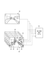
図1は、本実施形態の周辺監視装置が搭載される車両10の模式的な平面図である。車両10は、例えば、内燃機関(エンジン、図示されず)を駆動源とする自動車(内燃機関自動車)であってもよいし、電動機(モータ、図示されず)を駆動源とする自動車(電気自動車、燃料電池自動車等)であってもよいし、それらの双方を駆動源とする自動車(ハイブリッド自動車)であってもよい。また、車両10は、種々の変速装置を搭載することができるし、内燃機関や電動機を駆動するのに必要な種々の装置(システム、部品等)を搭載することができる。また、車両10における車輪12(前輪12F、後輪12R)の駆動に関わる装置の方式、個数、及び、レイアウト等は、種々に設定することができる。 FIG. 1 is a schematic plan view of a vehicle 10 on which a perimeter monitoring device of this embodiment is mounted. The vehicle 10 may be, for example, an automobile (internal combustion engine automobile) using an internal combustion engine (engine, not shown) as a drive source, or an automobile (electric automobile) using an electric motor (motor, not shown) as a drive source. , a fuel cell vehicle, etc.), or a vehicle (hybrid vehicle) using both of them as a driving source. In addition, the vehicle 10 can be equipped with various transmission devices, and can be equipped with various devices (systems, parts, etc.) necessary for driving the internal combustion engine and the electric motor. Further, the system, number, layout, etc. of the devices involved in driving the wheels 12 (the front wheels 12F and the rear wheels 12R) of the vehicle 10 can be set variously.

図1に例示されるように、車両10には、複数の撮像部14として、例えば四つの撮像部14a~14dが設けられている。撮像部14は、例えば、CCD(Charge Coupled Device)やCIS(CMOS image sensor)等の撮像素子を内蔵するデジタルカメラである。撮像部14は、所定のフレームレートで動画データ(撮像画像データ)を出力することができる。撮像部14は、それぞれ、広角レンズまたは魚眼レンズを有し、水平方向には例えば140°~220°の範囲を撮影することができる。また、例えば、車両10の外周部に配置される撮像部14(14a~14d)の光軸は斜め下方に向けて設定されている場合もある。よって、撮像部14(14a~14d)は、車両10が移動可能な路面や路面に付されたマーク(矢印や区画線、駐車スペースを示す駐車枠、車線分離線等)や物体(障害物として、例えば、歩行者、他車両等)を含む車両10の外部の周辺環境を逐次撮影し、撮像画像データとして出力する。 As illustrated in FIG. 1, the vehicle 10 is provided with, for example, four imaging units 14a to 14d as the plurality of imaging units 14. As shown in FIG. The imaging unit 14 is, for example, a digital camera incorporating an imaging element such as a CCD (Charge Coupled Device) or a CIS (CMOS image sensor). The imaging unit 14 can output moving image data (captured image data) at a predetermined frame rate. The imaging units 14 each have a wide-angle lens or a fish-eye lens, and can photograph a horizontal range of, for example, 140° to 220°. In addition, for example, the optical axis of the imaging unit 14 (14a to 14d) arranged in the outer peripheral portion of the vehicle 10 may be set obliquely downward. Therefore, the imaging unit 14 (14a to 14d) can detect road surfaces on which the vehicle 10 can move and marks (arrows, lane markings, parking frames indicating parking spaces, lane separation lines, etc.) and objects (such as obstacles) attached to the road surface. , pedestrians, other vehicles, etc.) are sequentially captured and output as captured image data.

撮像部14aは、例えば、車両10の前側、すなわち車両前後方向の前方側で車幅方向のほぼ中央の端部、例えばフロントバンパ10aやフロントグリル等に設けられて、車両10の前端部(例えばフロントバンパ10a)を含む前方画像を撮像可能である。また、撮像部14bは、例えば、車両10の後側、すなわち車両前後方向の後方側で車幅方向のほぼ中央の端部、例えばリヤバンパ10bの上方位置に設けられて、車両10の後端部(例えばリヤバンパ10b)を含む後方領域を撮像可能である。また、撮像部14cは、例えば、車両10の右側の端部、例えば右側のドアミラー10cに設けられて、車両10の右側方を中心とする領域(例えば右前方から右後方の領域)を含む右側方画像を撮像可能である。撮像部14dは、例えば、車両10の左側の端部、例えば左側のドアミラー10dに設けられて、車両10の左側方を中心とする領域(例えば左前方から左後方の領域)を含む左側方画像を撮像可能である。 The imaging unit 14a is provided, for example, on the front side of the vehicle 10, that is, on the front side in the vehicle longitudinal direction and at the substantially central end portion in the vehicle width direction, such as the front bumper 10a or the front grille, and is provided at the front end portion of the vehicle 10 (for example, A forward image including the front bumper 10a) can be captured. The imaging unit 14b is provided, for example, on the rear side of the vehicle 10, that is, on the rear side in the vehicle front-rear direction and substantially at the center in the vehicle width direction, for example, at a position above the rear bumper 10b. (For example, the rear bumper 10b) can be imaged. Further, the imaging unit 14c is provided, for example, at the right end of the vehicle 10, for example, at the right side door mirror 10c, and includes an area centered on the right side of the vehicle 10 (for example, an area from the front right to the rear right). It is possible to capture two-dimensional images. The imaging unit 14d is provided, for example, at the left end of the vehicle 10, for example, the left side door mirror 10d, and captures a left side image including an area centered on the left side of the vehicle 10 (for example, an area from the front left to the rear left). can be imaged.

例えば、撮像部14a~14dで得られた各撮像画像データは、それぞれ演算処理や画像処理を実行することで、車両10の周囲それぞれの方向における画像を表示したり周辺監視を実行したりすることができる。また、各撮像画像データに基づいて、演算処理や画像処理を実行することで、より広い視野角の画像を生成したり、車両10を上方や前方、側方等から見た仮想的な画像(俯瞰画像(平面画像)や側方視画像、正面視画像等)を生成して表示したり、周辺監視を実行したりすることができる。 For example, each captured image data obtained by the imaging units 14a to 14d is subjected to arithmetic processing and image processing, respectively, so that an image in each direction around the vehicle 10 can be displayed and surroundings can be monitored. can be done. Further, by executing arithmetic processing and image processing based on each captured image data, an image with a wider viewing angle can be generated, and a virtual image ( A bird's-eye view image (planar image), a side view image, a front view image, etc.) can be generated and displayed, and surroundings can be monitored.

各撮像部14で撮像された撮像画像データは、上述したように、車両10の周囲の状況を運転者等の利用者に提供するために、車室内の表示装置に表示される。また、撮像画像データは、各種検出や検知を行う処理装置(処理部)に提供され、車両10を制御するために利用することができる。 The captured image data captured by each imaging unit 14 is displayed on the display device in the vehicle interior in order to provide the user such as the driver with the situation around the vehicle 10, as described above. Also, the captured image data can be provided to a processing device (processing unit) that performs various types of detection and detection, and can be used to control the vehicle 10 .

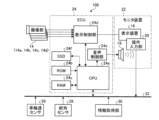
図2は、車両10に搭載される周辺監視装置を含む車両制御システム100の構成の例示的なブロック図である。車両10の車室内には、表示装置16や、音声出力装置18が設けられている。表示装置16は、例えば、LCD(liquid crystal display)や、OELD(organic electroluminescent display)等である。音声出力装置18は、例えば、スピーカである。また、表示装置16は、例えば、タッチパネル等、透明な操作入力部20で覆われている。使用者(例えば、運転者)は、操作入力部20を介して表示装置16の表示画面に表示される画像を視認することができる。また、利用者は、表示装置16の表示画面に表示される画像に対応した位置で、手指等で操作入力部20を触れたり押したり動かしたりして操作することで、操作入力を実行することができる。これら表示装置16や、音声出力装置18、操作入力部20等は、例えば、車両10のダッシュボードの車幅方向すなわち左右方向の例えば中央部に位置されたモニタ装置22に設けられている。モニタ装置22は、スイッチや、ダイヤル、ジョイスティック、押しボタン等の不図示の操作入力部を有することができる。モニタ装置22は、例えば、ナビゲーションシステムやオーディオシステムと兼用されうる。 FIG. 2 is an exemplary block diagram of the configuration of a vehicle control system 100 including a perimeter monitoring device mounted on the vehicle 10. As shown in FIG. A display device 16 and an audio output device 18 are provided in the interior of the vehicle 10 . The display device 16 is, for example, an LCD (liquid crystal display), an OELD (organic electroluminescent display), or the like. The audio output device 18 is, for example, a speaker. Also, the display device 16 is covered with a transparent operation input unit 20 such as a touch panel. A user (for example, a driver) can visually recognize an image displayed on the display screen of the display device 16 via the operation input unit 20 . In addition, the user can perform operation input by touching, pressing, or moving the operation input unit 20 with fingers or the like at a position corresponding to the image displayed on the display screen of the display device 16. can be done. The display device 16, the audio output device 18, the operation input unit 20, and the like are provided, for example, in a monitor device 22 positioned, for example, in the central portion of the dashboard of the vehicle 10 in the vehicle width direction, that is, in the left-right direction. The monitor device 22 can have operation input units (not shown) such as switches, dials, joysticks, and push buttons. The monitor device 22 can also be used, for example, as a navigation system or an audio system.

また、図2に例示されるように、車両制御システム100(周辺監視装置を含む)は、撮像部14(14a~14d)やモニタ装置22に加え、ECU24(electronic control unit)、車輪速センサ26、舵角センサ28、情報取得部30等が含まれる。車両制御システム100において、ECU24やモニタ装置22、車輪速センサ26、舵角センサ28、情報取得部30等は、電気通信回線としての車内ネットワーク32を介して電気的に接続されている。車内ネットワーク32は、例えば、CAN(controller area network)として構成されている。ECU24は、車内ネットワーク32を通じて制御信号を送ることで、各種システムの制御が実行できる。また、ECU24は、車内ネットワーク32を介して、操作入力部20や各種スイッチの操作信号等、車輪速センサ26、舵角センサ28等の各種センサの検出信号等、情報取得部30が取得可能な位置情報等の情報を、受け取ることができる。なお、車内ネットワーク32には、車両10を走行させるための種々のシステム(操舵システム、ブレーキシステム、駆動システム等)や種々のセンサが接続されているが、図2において、本実施形態の周辺監視装置で必須ではない構成は図示を省略するとともに、その説明を省略する。 Further, as illustrated in FIG. 2, the vehicle control system 100 (including a peripheral monitoring device) includes an imaging unit 14 (14a to 14d), a monitor device 22, an ECU 24 (electronic control unit), a wheel speed sensor 26 , a steering angle sensor 28, an information acquisition unit 30, and the like. In the vehicle control system 100, the ECU 24, the monitor device 22, the wheel speed sensor 26, the steering angle sensor 28, the information acquisition section 30, and the like are electrically connected via an in-vehicle network 32 as an electric communication line. The in-vehicle network 32 is configured as, for example, a CAN (controller area network). The ECU 24 can control various systems by sending control signals through the in-vehicle network 32 . In addition, the ECU 24 can acquire information such as operation signals of the operation input unit 20 and various switches, detection signals of various sensors such as the wheel speed sensor 26 and the steering angle sensor 28, etc. via the in-vehicle network 32. Information such as location information can be received. Various systems (a steering system, a braking system, a drive system, etc.) and various sensors for running the vehicle 10 are connected to the in-vehicle network 32. In FIG. Configurations that are not essential to the apparatus are omitted from the illustration, and descriptions thereof are omitted.

ECU24は、撮像部14から取得した撮像画像データに基づいて生成した周辺画像等や音声に関するデータをモニタ装置22へ送信する。ECU24は、例えば、CPU24a(central processing unit)や、ROM24b(read only memory)、RAM24c(random access memory)、表示制御部24d、音声制御部24e、SSD24f(solid state drive、フラッシュメモリ)等を有している。 The ECU 24 transmits, to the monitor device 22 , peripheral images generated based on the captured image data acquired from the imaging unit 14 and data related to audio. The ECU 24 includes, for example, a CPU 24a (central processing unit), a ROM 24b (read only memory), a RAM 24c (random access memory), a display control section 24d, an audio control section 24e, and an SSD 24f (solid state drive, flash memory). ing.

CPU24aは、ROM24b等の不揮発性の記憶装置に記憶された(インストールされた)プログラムを読み出し、当該プログラムに従って演算処理を実行する。ROM24bは、各プログラム及びプログラムの実行に必要なパラメータ、撮像画像を複製する際に利用する、予め複数のデータを用いて学習させた学習済みモデル等を記憶する。RAM24cは、CPU24aが復元画像の復元処理を実行する際のワークエリアとして使用されるとともに、CPU24aでの演算で用いられる各種のデータ(撮像部14で逐次(時系列的に)撮像される撮像画像データ等)の一時的な格納エリアとして利用される。また、表示制御部24dは、ECU24での演算処理のうち、主として、表示装置16で表示される画像データの合成等を実行する。また、音声制御部24eは、ECU24での演算処理のうち、主として、音声出力装置18で出力される音声データの処理を実行する。SSD24fは、書き換え可能な不揮発性の記憶部であって、ECU24の電源がオフされた場合にあってもデータを記憶することができる。なお、CPU24aや、ROM24b、RAM24c等は、同一パッケージ内に集積されうる。また、ECU24は、CPU24aに替えて、DSP(digital signal processor)等の他の論理演算プロセッサや論理回路等が用いられる構成であってもよい。また、SSD24fに替えてHDD(hard disk drive)が設けられてもよいし、SSD24fやHDDは、ECU24とは別に設けられてもよい。 The CPU 24a reads a program stored (installed) in a non-volatile storage device such as the ROM 24b, and executes arithmetic processing according to the program. The ROM 24b stores each program, parameters necessary for executing the program, and a learned model which is learned using a plurality of data in advance and which is used when copying a captured image. The RAM 24c is used as a work area when the CPU 24a executes restoration processing of a restored image, and stores various data used in calculations by the CPU 24a (captured images sequentially (time-sequentially) captured by the imaging unit 14). data, etc.) is used as a temporary storage area. In addition, the display control unit 24 d mainly executes the synthesis of image data to be displayed on the display device 16 among the arithmetic processing in the ECU 24 . In addition, the audio control unit 24e mainly executes processing of audio data output from the audio output device 18 among the arithmetic processing in the ECU 24. FIG. The SSD 24f is a rewritable non-volatile storage unit, and can store data even when the power of the ECU 24 is turned off. The CPU 24a, ROM 24b, RAM 24c, etc. can be integrated in the same package. Further, the ECU 24 may have a configuration in which another logical operation processor such as a DSP (digital signal processor), a logic circuit, or the like is used instead of the CPU 24a. A HDD (hard disk drive) may be provided instead of the SSD 24f, or the SSD 24f and the HDD may be provided separately from the ECU 24.

車輪速センサ26は、車輪12の回転量や単位時間当たりの回転数を検出するセンサである。車輪速センサ26は、各車輪12に配置され、各車輪12で検出した回転数を示す車輪速パルス数をセンサ値として出力する。車輪速センサ26は、例えば、ホール素子などを用いて構成されうる。CPU24aは、車輪速センサ26から取得した検出値に基づいて車両10の車速や加速度等を演算し、各種制御を実行する。CPU24aは、各車輪速センサ26の検出値に基づいて車両10の車速を算出する場合、四輪のうち最も小さな検出値の車輪12の速度に基づき車両10の車速を決定し、各種制御を実行する。なお、車輪速センサ26は、図示を省略したブレーキシステムに設けられている場合もある。その場合、CPU24aは、車輪速センサ26の検出値をブレーキシステムを介して取得してもよい。 The wheel speed sensor 26 is a sensor that detects the amount of rotation of the wheel 12 and the number of rotations per unit time. The wheel speed sensor 26 is arranged at each wheel 12 and outputs a wheel speed pulse number indicating the number of revolutions detected at each wheel 12 as a sensor value. The wheel speed sensor 26 can be configured using, for example, a Hall element. The CPU 24a calculates the vehicle speed, acceleration, etc. of the vehicle 10 based on the detected value obtained from the wheel speed sensor 26, and executes various controls. When calculating the vehicle speed of the vehicle 10 based on the detection values of the wheel speed sensors 26, the CPU 24a determines the vehicle speed of the vehicle 10 based on the speed of the wheel 12 having the smallest detection value among the four wheels, and executes various controls. do. Note that the wheel speed sensor 26 may be provided in a brake system (not shown). In that case, the CPU 24a may acquire the detection value of the wheel speed sensor 26 via the brake system.

舵角センサ28は、例えば、ステアリングホイール等の操舵部の操舵量を検出するセンサである。舵角センサ28は、例えば、ホール素子などを用いて構成される。CPU24aは、運転者による操舵部の操舵量や、例えば駐車支援を実行する際の自動操舵時の前輪12Fの操舵量等を、舵角センサ28から取得して各種制御を実行する。 The steering angle sensor 28 is, for example, a sensor that detects the steering amount of a steering portion such as a steering wheel. The steering angle sensor 28 is configured using, for example, a Hall element. The CPU 24a acquires from the steering angle sensor 28 the steering amount of the steering unit by the driver, the steering amount of the front wheels 12F during automatic steering when executing parking assistance, and the like, and executes various controls.

情報取得部30は、GPS(Global Positioning System)とうから送信されるGPS信号を受信することで車両10の現在の位置を取得したり、外部の情報センタ等が送信する気象情報等を取得したりすることが可能で、取得した情報を各種制御に利用する。なお、車両10の位置情報や外部情報等は、モニタ装置22がナビゲーションシステムを供える場合、ナビゲーションシステム側で取得してもよい。 The information acquisition unit 30 acquires the current position of the vehicle 10 by receiving GPS signals transmitted from a GPS (Global Positioning System), or acquires weather information or the like transmitted by an external information center or the like. The acquired information is used for various controls. In addition, when the monitor device 22 is provided with a navigation system, the position information of the vehicle 10, the external information, and the like may be acquired by the navigation system.

本実施形態では、ECU24は、ハードウェアとソフトウェア(制御プログラム)が協働することにより、撮像部14で撮像された撮像画像に汚れが存在する場合、その撮像画像から汚れを取り除いたかのような画像、つまり、汚れが存在しない状態を復元した「復元画像」の生成処理(復元処理)を司る。図3は、ECU24に含まれるCPU24aにおいて、実施形態にかかる周辺監視装置(周辺監視部34)が実現される場合の構成を例示的に示すブロック図である。 In the present embodiment, the ECU 24 cooperates with hardware and software (control program) to produce an image as if the dirt had been removed from the captured image captured by the imaging unit 14 when dirt is present in the captured image. , that is, it governs the generation processing (restoration processing) of a “restored image” that restores a state in which dirt does not exist. FIG. 3 is a block diagram exemplifying a configuration in which the CPU 24a included in the ECU 24 implements the surroundings monitoring device (the surroundings monitoring unit 34) according to the embodiment.

周辺監視部34は、撮像画像に存在する汚れを取り除いたかのような復元画像を生成する復元処理機能を実現するための各種モジュールを含む。例えば、周辺監視部34は、受付部36、画像取得部38、汚れ情報取得部40、速度取得部42、復元処理部44、報知部46、出力部48等を含む。これらのモジュールは、専用のハードウェアとして構成されてもよい。なお、後述するが復元処理部44で実行するディープラーニング等を用いた処理では膨大な並列計算が必要とされため、例えばGPU(Graphics Processing Unit)やFPGA(Field-Programmable Gate Array)等を活用してもよい。周辺監視部34には、実際に周辺監視処理として、障害物検出や白線検出等を実行するためのモジュールが含まれるが、図3においては、復元処理に必要なモジュール以外は、図示を省略するとともに、その説明を省略する。また、復元処理部44は、第1復元処理部44a、第2復元処理部44b、復元実行判定部44c等の詳細モジュールを含み、復元実行判定部44cは、さらに、閾値変更部44c1を含む。 The surroundings monitoring unit 34 includes various modules for realizing a restoration processing function of generating a restored image as if dirt in the captured image were removed. For example, the periphery monitoring unit 34 includes a reception unit 36, an image acquisition unit 38, a dirt information acquisition unit 40, a speed acquisition unit 42, a restoration processing unit 44, a notification unit 46, an output unit 48, and the like. These modules may be configured as dedicated hardware. As will be described later, processing using deep learning or the like executed by the restoration processing unit 44 requires a huge amount of parallel calculation, so for example, a GPU (Graphics Processing Unit) or FPGA (Field-Programmable Gate Array) is used. may The perimeter monitoring unit 34 actually includes modules for executing obstacle detection, white line detection, etc. as perimeter monitoring processing, but in FIG. , and the description thereof will be omitted. The restoration processing unit 44 includes detailed modules such as a first restoration processing unit 44a, a second restoration processing unit 44b, and a restoration execution determination unit 44c. The restoration execution determination unit 44c further includes a threshold change unit 44c1.

ROM24bは、CPU24aで実行される各種プログラムの他、予め機械学習によって構築された複数の学習済みモデルを格納する。ROM24bは、例えば、汚れ情報学習済みモデル格納部50、第1学習済みモデル格納部52、第2学習済みモデル格納部54等を含む。汚れ情報学習済みモデル格納部50は、撮像画像に汚れが存在するか否か、その撮像画像に汚れが存在する場合、汚れの位置や大きさ等の汚れ情報を取得する場合に利用する汚れ情報学習済みモデルを格納する。第1学習済みモデル格納部52は、復元処理部44で第1復元画像を生成する場合に利用する第1学習済みモデルを格納する。第2学習済みモデル格納部54は、第1学習済みモデルを用いて復元する第1復元画像の精度をさらに向上する場合に利用する第2学習済みモデルを格納する。なお、ROM24bは、この他、復元処理部44が復元処理を実行するか否かを判定する場合に参照する閾値を格納した閾値データ格納部55を備える。また、RAM24cは、復元処理部44で復元画像を生成する場合に利用する撮像画像として、時系列的に撮像された複数の撮像画像データを一時的に格納しておく、撮像画像格納部56を含む。 The ROM 24b stores various programs executed by the CPU 24a as well as a plurality of trained models constructed in advance by machine learning. The ROM 24b includes, for example, a dirt information learned model storage unit 50, a first learned model storage unit 52, a second learned model storage unit 54, and the like. The dirt information learned model storage unit 50 stores dirt information used when acquiring dirt information such as whether or not dirt exists in the captured image, and when dirt exists in the captured image, such as the position and size of the dirt. Store trained models. The first trained model storage unit 52 stores the first trained model used when the restoration processing unit 44 generates the first restored image. The second trained model storage unit 54 stores a second trained model that is used to further improve the accuracy of the first restored image that is restored using the first trained model. The ROM 24b also includes a threshold data storage unit 55 that stores a threshold value that the restoration processing unit 44 refers to when determining whether or not to execute restoration processing. The RAM 24c also includes a captured image storage unit 56 that temporarily stores a plurality of captured image data captured in time series as captured images to be used when a restored image is generated by the restoration processing unit 44. include.

汚れ情報学習済みモデル格納部50に格納される汚れ情報学習済みモデルは、汚れ情報取得部40で利用される、復元対象の撮像画像における汚れ(例えば、雨滴等)の存在する確率をピクセル毎に算出するためのモデルである。汚れ情報学習済みモデルを構築する場合、例えば、汚れなしを示す値を「0」とし、汚れありを示す値を「1」とする。そして、学習用画像のピクセル毎に汚れである確からしさを「0~1」の間の評価値で示す。この評価値を用いた学習用画像に基づいて、例えば、ディープラーニング等の機械学習手法によって学習させることで、汚れ情報学習済みモデルを構築する。したがって、撮像部14で撮像した撮像画像(データ)を汚れ情報学習済みモデルに入力することで、評価値が「1」に近いピクセルの多さが判定され、汚れの位置や汚れの大きさ(領域の大きさ)が出力される。 The dirt information learned model stored in the dirt information learned model storage unit 50 is used by the dirt information acquisition unit 40. The probability that dirt (for example, raindrops) exists in the captured image to be restored is calculated for each pixel. It is a model for calculation. When constructing a dirt information-learned model, for example, a value indicating no dirt is set to "0" and a value indicating that there is dirt is set to "1". Then, the probability that each pixel of the learning image is dirty is indicated by an evaluation value between “0 and 1”. Based on the learning image using this evaluation value, for example, a machine learning method such as deep learning is used to construct a dirt information-learned model. Therefore, by inputting the captured image (data) captured by the imaging unit 14 to the dirt information trained model, the number of pixels whose evaluation value is close to "1" is determined, and the position and size of the dirt ( region size) is output.

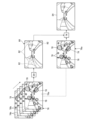
第1学習済みモデル格納部52に格納される第1学習済みモデルは、第1復元処理部44aで利用されるモデルである。第1学習済みモデルは、車両10に備えられた撮像部14で車両10が移動している際に時系列的に撮像される複数の撮像画像のうち、最新撮像画像において汚れにより隠蔽された領域を復元させた第1復元画像を復元画像として生成する場合に利用される。第1学習済みモデルの構築概念を図4に示す。図4に示すように、第1学習済みモデル64は、学習用汚れ62(例えば、雨滴等)が存在しない第1学習用画像58と、この第1学習用画像58に学習用汚れ62を存在させた、複数の第1学習用汚れ画像60と、の関係を例えば、ディープラーニング等の機械学習手法によって学習させたモデルである。第1学習済みモデル64を用いた復元処理の詳細は後述する。 The first trained model stored in the first trained model storage unit 52 is a model used by the first restoration processing unit 44a. The first trained model is a region hidden by dirt in the latest captured image among a plurality of captured images captured in time series by the imaging unit 14 provided in the vehicle 10 while the vehicle 10 is moving. is used to generate a restored image as a restored image. FIG. 4 shows the construction concept of the first trained model. As shown in FIG. 4, the first trained model 64 includes a first learning image 58 in which no learning dirt 62 (for example, raindrops) exists, and a learning dirt 62 in this first learning image 58. This model is a model in which the relationship between the plurality of first learning dirt images 60 that have been obtained is learned by, for example, a machine learning method such as deep learning. Details of the restoration process using the first trained model 64 will be described later.

第2学習済みモデル格納部54に格納される第2学習済みモデルは、第2復元処理部44bで利用されるモデルである。第2学習済みモデルは、第1学習済みモデル64で生成した第1復元画像と、第1復元画像を生成する際に入力した複数の撮像画像のうち最新撮像画像とに基づいて、より復元精度の高い第2復元画像を復元画像として復元する際に利用される。第2学習済みモデルの構築概念を図5に示す。図5に示すように、第2学習済みモデル74は、第1学習済みモデル64に、学習用汚れが存在する、複数の第2学習用汚れ画像66を入力して生成した復元画像68(第1復元画像)と、当該復元画像68を復元する際に利用した複数の第2学習用汚れ画像66のうち最新の最新学習用汚れ画像66aとの関係を、例えば、ディープラーニング等の機械学習手法によって学習させたモデルである。第2学習済みモデル74は、第1学習済みモデル64によって生成される復元画像68において発生する、ぼやけや不連続等の不自然領域70を最新学習用汚れ画像66aで汚れ72の存在しない鮮明部分(エッジがきれいに出ている部分)の情報を用いて復元するものである。第2学習済みモデル74を用いた復元処理の詳細は後述する。 The second trained model stored in the second trained model storage unit 54 is a model used by the second restoration processing unit 44b. The second trained model has higher restoration accuracy based on the first restored image generated by the first trained model 64 and the latest captured image among the plurality of captured images input when generating the first restored image. is used when restoring the second restored image having a high value as a restored image. FIG. 5 shows the construction concept of the second trained model. As shown in FIG. 5, the second trained model 74 is a restored image 68 (first 1 restored image) and the latest latest learning dirt image 66a out of the plurality of second learning dirt images 66 used when restoring the restored image 68, for example, using a machine learning technique such as deep learning. It is a model trained by The second trained model 74 replaces unnatural areas 70 such as blurring and discontinuities that occur in the restored image 68 generated by the first trained model 64 with the latest learning dirt image 66a as clear portions where no dirt 72 exists. It is to restore using the information of (the part where the edge appears clearly). Details of the restoration process using the second trained model 74 will be described later.

図3に戻り、受付部36は、復元画像の生成が要求される場合の要求信号を受け付ける。復元画像の生成は、例えば、車両10の走行中、撮像画像に汚れが検出された場合に自動的に実行されてもよい(自動復元モード)。また、車両10の利用者(例えば、運転者)が操作入力部20等を介して希望するタイミング(例えば、表示装置16に表示されている画像が汚れで見にくくなった場合等)に復元画像の生成を手動で実行させてもよい(手動復元モード)。受付部36は、復元画像の生成が自動的に要求される場合は、周辺監視部34側からの要求信号を受付け、復元画像の生成が手動で要求される場合は、操作入力部20等からの操作信号を車内ネットワーク32を介して受け付ける。 Returning to FIG. 3, the receiving unit 36 receives a request signal when generation of a restored image is requested. The generation of the restored image may be automatically executed, for example, when dirt is detected in the captured image while the vehicle 10 is running (automatic restoration mode). In addition, the user of the vehicle 10 (for example, the driver) can restore the restored image at a desired timing via the operation input unit 20 (for example, when the image displayed on the display device 16 is dirty and difficult to see). Generation can also be run manually (manual restore mode). The reception unit 36 receives a request signal from the periphery monitoring unit 34 side when the restoration image generation is automatically requested, and receives a request signal from the operation input unit 20 or the like when the restoration image generation is manually requested. through the in-vehicle network 32.

画像取得部38は、各撮像部14で撮像された撮像画像データをフレーム毎に取得し、RAM24cの撮像画像格納部56に格納する。画像取得部38は、車両10(ECU24)の電源がONの場合に撮像部14で撮像される撮像画像データを逐次取得することができる。画像取得部38は、各撮像部14(14a~14d)が撮像した撮像画像データを撮像部14毎に識別して取得し、撮像画像格納部56に格納する。したがって、撮像画像格納部56には、各撮像部14毎に時系列的に連続するフレームデータとして撮像画像データが格納される。撮像画像格納部56は、一定期間、例えば、3~5秒分の撮像画像データが格納可能で、逐次新しい撮像画像データを上書する。したがって、撮像画像格納部56は、最新撮像画像および最新撮像画像から時系列的に所定期間遡った複数の過去画像を復元処理部44に提供することができる。また、撮像画像格納部56が、撮像画像データを一定期間格納する場合の別の例として、例えば、撮像画像格納部56は、車両10が一定距離走行する間の撮像画像データを格納するようにしてもよい。 The image acquisition unit 38 acquires captured image data captured by each imaging unit 14 for each frame, and stores the captured image data in the captured image storage unit 56 of the RAM 24c. The image acquisition unit 38 can sequentially acquire captured image data captured by the imaging unit 14 when the vehicle 10 (ECU 24) is powered on. The image acquisition unit 38 identifies and acquires the captured image data captured by each of the imaging units 14 ( 14 a to 14 d ), and stores the captured image data in the captured image storage unit 56 . Therefore, the captured image data is stored in the captured image storage unit 56 as time-series continuous frame data for each image capturing unit 14 . The captured image storage unit 56 can store captured image data for a certain period of time, for example, 3 to 5 seconds, and successively overwrites new captured image data. Therefore, the captured image storage unit 56 can provide the restoration processing unit 44 with the latest captured image and a plurality of past images obtained by chronologically going back a predetermined period from the latest captured image. As another example of the case where the captured image storage unit 56 stores captured image data for a certain period of time, for example, the captured image storage unit 56 stores captured image data while the vehicle 10 travels a certain distance. may

汚れ情報取得部40は、撮像画像に汚れが存在するか否か、および汚れが存在する場合は、その汚れの位置や大きさを、ROM24bの汚れ情報学習済みモデル格納部50から読み出した汚れ情報学習済みモデルに撮像画像を入力することで取得する。汚れ情報取得部40は、取得した汚れ情報を逐次復元処理部44に提供する。汚れが、例えば、泥はねや埃の付着の場合、車両10が走行する場合でも撮像部14のレンズ上で移動する可能性は低い。一方、汚れが雨滴等のように容易に移動したり変形したりするものの場合、車両10の走行時に受ける風圧等により撮像部14のレンズ上で汚れが移動したり、大きさが変化したりする可能性がある。そのため、汚れ情報取得部40は、少なくとも復元処理部44が復元処理を実行している間は、撮像画像毎に汚れ情報の取得を逐次実行する。 The dirt information acquisition unit 40 determines whether or not dirt exists in the captured image, and if the dirt exists, the dirt information read out from the dirt information learned model storage unit 50 of the ROM 24b. Acquired by inputting captured images into the trained model. The stain information acquisition unit 40 sequentially provides the acquired stain information to the restoration processing unit 44 . If the dirt is, for example, splashed mud or adhering dust, it is unlikely that the dirt will move on the lens of the imaging unit 14 even when the vehicle 10 is running. On the other hand, if the dirt is easily moved or deformed, such as raindrops, the wind pressure or the like received while the vehicle 10 is running causes the dirt to move or change in size on the lens of the imaging unit 14 . there is a possibility. Therefore, the stain information acquisition unit 40 sequentially acquires stain information for each captured image at least while the restoration processing unit 44 is executing restoration processing.

速度取得部42は、車輪速センサ26の検出値に基づき、車両10の現在の車速や加速度を取得する。速度取得部42は、車両10の車速を復元処理部44に提供し、復元処理部44において、復元処理を実行するか否かを判定する場合に利用される。 The speed acquisition unit 42 acquires the current vehicle speed and acceleration of the vehicle 10 based on the detection value of the wheel speed sensor 26 . The speed acquisition unit 42 provides the vehicle speed of the vehicle 10 to the restoration processing unit 44 and is used by the restoration processing unit 44 to determine whether or not to execute restoration processing.

復元処理部44は、復元対象の撮像画像の復元を行う場合、第1復元処理部44aと第2復元処理部44bとを用いた二段階処理を実行する。図6は、復元処理部44において第1復元処理部44aと第2復元処理部44bとを用いて二段階で復元処理を実行する場合にイメージを示す例示的かつ模式的な説明図である。なお、図6は、復元対象の撮像画像として、撮像部14のうち撮像部14bで撮像した後方画像を復元する場合を一例として示している。 When restoring a captured image to be restored, the restoration processing unit 44 executes two-stage processing using a first restoration processing unit 44a and a second restoration processing unit 44b. FIG. 6 is an exemplary and schematic explanatory diagram showing an image when restoration processing is executed in two stages using the first restoration processing unit 44a and the second restoration processing unit 44b in the restoration processing unit 44. FIG. Note that FIG. 6 shows, as an example, a case where a rearward image captured by the imaging unit 14b of the imaging unit 14 is restored as a captured image to be restored.

まず、第1復元処理部44aは、撮像部14(撮像部14b)で逐次撮像され、RAM24cの撮像画像格納部56に時系列的に格納された複数の撮像画像76を第1学習済みモデル64に入力する。この場合、撮像画像76に存在する汚れ78(例えば、雨滴)の位置や大きさに関する汚れ情報は、汚れ情報取得部40から提供される汚れ情報に基づいて認識可能であり、第1学習済みモデル64では、汚れ78の存在する可能性の高い領域に対して復元処理が順次実行されることになる。この場合、復元処理は、時系列的な複数の撮像画像76のうち最新の最新撮像画像76aに対して実行される。このとき、走行する車両10の撮像部14で撮像された、最新撮像画像76aより時系列的に過去の過去画像76bには、最新撮像画像76a上に存在する汚れ78で隠蔽された領域が、汚れ78で隠蔽されることなく写っている可能性がある。したがって、第1学習済みモデル64は、複数の過去画像76bの情報が入力されることにより、汚れ78で隠蔽された領域が高確率で復元された第1復元画像80の生成が可能となり、復元画像の品質を向上することができる。 First, the first restoration processing unit 44a converts a plurality of captured images 76 sequentially captured by the imaging unit 14 (image capturing unit 14b) and stored in time series in the captured image storage unit 56 of the RAM 24c into the first trained model 64. to enter. In this case, dirt information about the position and size of the dirt 78 (for example, raindrops) present in the captured image 76 can be recognized based on the dirt information provided by the dirt information acquisition unit 40, and the first learned model At 64, restoration processing will be performed sequentially on areas where dirt 78 is likely to be present. In this case, the restoration process is performed on the latest captured image 76 a among the plurality of time-series captured images 76 . At this time, in a past image 76b that is chronologically older than the latest captured image 76a captured by the imaging unit 14 of the running vehicle 10, an area that is hidden by the dirt 78 present on the latest captured image 76a is There is a possibility that it is captured without being hidden by the dirt 78 . Therefore, the first trained model 64 can generate the first restored image 80 in which the area hidden by the dirt 78 is restored with a high probability by inputting the information of the plurality of past images 76b. Image quality can be improved.

ところで、第1学習済みモデル64は、前述したように、最新撮像画像76aに加え複数の過去画像76bを用いて第1復元画像80を生成するため、汚れ78が存在しない領域にも復元処理の影響がでて、第1復元画像80において、ぼやけたり、不連続になったりする不自然領域82が生じる場合がある。そこで、第2復元処理部44bは、第1学習済みモデル64によって生成された第1復元画像80と、この第1復元画像80を生成する際の使用した複数の撮像画像76のうち最新撮像画像76aとを第2学習済みモデル74に入力して第2復元画像84を生成する。この場合、第2復元画像84の復元の際に第1復元画像80に対して最もエッジが際立っている可能性の高い最新撮像画像76aを考慮させることにより、不自然領域82を修正したより鮮明な第2復元画像84を復元画像として生成することができる。 By the way, as described above, the first trained model 64 generates the first restored image 80 using a plurality of previous images 76b in addition to the latest captured image 76a. As a result, an unnatural area 82 that is blurry or discontinuous may occur in the first restored image 80 . Therefore, the second restoration processing unit 44b generates the first restored image 80 generated by the first trained model 64 and the latest captured image among the plurality of captured images 76 used to generate the first restored image 80. 76a are input to the second trained model 74 to generate a second restored image 84. FIG. In this case, when restoring the second restored image 84, the latest captured image 76a, which is most likely to have the most conspicuous edge relative to the first restored image 80, is taken into consideration, thereby correcting the unnatural region 82 and making it clearer. A second restored image 84 can be generated as a restored image.

図3に戻り、復元処理部44は、復元実行判定部44cを備える。復元処理部44は、上述したように、最新撮像画像76aおよび過去画像76bを含む複数の撮像画像76を用いて復元処理を実行する。この場合、復元処理に利用できる過去画像76bは、最新撮像画像76aに写っているものが含まれるものに限られる。車両10が走行している場合、例えば、数秒前までに撮像された過去画像76bに限られる。このように、利用できる過去画像76bに制限がある状況では、最新撮像画像76aに存在する汚れ78が大きい場合、最新撮像画像76aおよび過去画像76bからなる複数の撮像画像76を用いて復元処理を実行しても十分な復元ができない場合がある。例えば、汚れ78が、所定の閾値で示す大きさを超えている場合、過去画像76bにおいても汚れ78で隠蔽され続いている物体が存在する可能がある。このような場合、最新撮像画像76aにおいて汚れ78が隠蔽している領域を十分に復元することができないため、復元処理部44による復元処理の実行は望ましくない。そこで、復元実行判定部44cは、復元条件が満たされない場合、復元処理を非実行としている。復元実行判定部44cは、汚れ情報取得部40が取得する汚れ情報に含まれる最新撮像画像76aの汚れの大きさと、所定の閾値と、の比較を行い、汚れの大きさが閾値以上の場合、十分な汚れ部分の復元が不可能であると判定し、第1復元処理部44a、第2復元処理部44bにおける復元処理を非実行とする。 Returning to FIG. 3, the restoration processing unit 44 includes a restoration execution determination unit 44c. As described above, the restoration processing unit 44 executes restoration processing using a plurality of captured images 76 including the latest captured image 76a and the past image 76b. In this case, the past images 76b that can be used for the restoration process are limited to those that include the images in the latest captured image 76a. When the vehicle 10 is running, for example, it is limited to the past image 76b captured up to several seconds ago. In this way, in a situation where the available past images 76b are limited, if the dirt 78 present in the latest captured image 76a is large, restoration processing is performed using a plurality of captured images 76 consisting of the latest captured image 76a and the past image 76b. Even if it is executed, sufficient restoration may not be possible. For example, when the dirt 78 exceeds the size indicated by the predetermined threshold, there is a possibility that an object continues to be hidden by the dirt 78 in the past image 76b. In such a case, it is not desirable to perform restoration processing by the restoration processing unit 44 because the area covered by the dirt 78 in the latest captured image 76a cannot be sufficiently restored. Therefore, the restoration execution determination unit 44c does not execute the restoration process when the restoration condition is not satisfied. The restoration execution determination unit 44c compares the stain size of the latest captured image 76a included in the stain information acquired by the stain information acquisition unit 40 with a predetermined threshold value. It is determined that restoration of a sufficiently dirty portion is impossible, and restoration processing in the first restoration processing section 44a and the second restoration processing section 44b is not executed.

なお、この場合、閾値は一定値としてもよいが、車両10の速度によって、復元ができる場合とできない場合が生じることがある。例えば、汚れ78の大きさが大きい場合でも車両10の移動速度が高い場合、最新撮像画像76aで隠蔽の原因になっている汚れ78が、過去画像76bでは最新撮像画像76aの隠蔽領域から離れた位置を隠蔽している可能性が高くなる。つまり、車両10の移動量が大きい場合、時系列的に遡った過去画像76bに、最新撮像画像76aにおいて汚れ78で隠蔽されている領域が写っている可能性が増加する。逆に、汚れ78の大きさが小さい場合でも車両10の移動速度が低い場合、最新撮像画像76aと過去画像76bとで汚れ78の移動量が小さい。そのため、時系列的に遡った過去画像76bを参照しても最新撮像画像76aにおいて汚れ78で隠蔽されている領域が隠蔽されたままの可能性が増加する。したがって、閾値変更部44c1は、車両10の車速と汚れ78との大きさに応じて、復元の可否を判定する場合の閾値を変更する。閾値変更部44c1は、車両10の車速と汚れ78の大きさと閾値とを関連付けた閾値マップをROM24bの閾値データ格納部55から読み出す。そして、閾値変更部44c1は、第1復元処理部44a、第2復元処理部44bにおける復元処理実行時に、速度取得部42から車両10の現在の車速を取得するとともに、汚れ情報取得部40が取得した汚れ情報から汚れ78の大きさを取得して、閾値マップを参照する。そして、閾値変更部44c1は、現在の状況において復元の可否を判定するための最も適した閾値を決定(変更)して、第1復元処理部44a、第2復元処理部44bに提供する。第1復元処理部44a、第2復元処理部44bでは、提供された閾値に基づき復元処理を実行するか否かの判定を行う。 In this case, the threshold value may be a constant value, but depending on the speed of the vehicle 10, restoration may or may not be possible. For example, when the moving speed of the vehicle 10 is high even when the size of the dirt 78 is large, the dirt 78 that causes concealment in the latest captured image 76a moves away from the concealment area of the latest captured image 76a in the previous image 76b. More likely to hide your location. In other words, when the amount of movement of the vehicle 10 is large, there is an increased possibility that the region hidden by the dirt 78 in the latest captured image 76a is captured in the past image 76b that goes back in time series. Conversely, even when the size of the dirt 78 is small, when the moving speed of the vehicle 10 is low, the amount of movement of the dirt 78 is small between the latest captured image 76a and the previous image 76b. Therefore, even if the past image 76b that goes back chronologically is referred to, the possibility that the area hidden by the dirt 78 in the latest captured image 76a remains hidden increases. Therefore, the threshold changing unit 44c1 changes the threshold for judging whether or not restoration is possible according to the vehicle speed of the vehicle 10 and the size of the dirt 78. FIG. The threshold change unit 44c1 reads out a threshold map that associates the vehicle speed of the vehicle 10, the size of the dirt 78, and the threshold from the threshold data storage unit 55 of the ROM 24b. Then, the threshold change unit 44c1 acquires the current vehicle speed of the vehicle 10 from the speed acquisition unit 42 and the dirt information acquisition unit 40 acquires the current speed of the vehicle 10 when executing the restoration processing in the first restoration processing unit 44a and the second restoration processing unit 44b. The size of the dirt 78 is obtained from the dirt information obtained, and the threshold map is referred to. Then, the threshold changing unit 44c1 determines (changes) the most appropriate threshold for determining whether restoration is possible in the current situation, and provides it to the first restoration processing unit 44a and the second restoration processing unit 44b. The first restoration processing unit 44a and the second restoration processing unit 44b determine whether or not to execute restoration processing based on the provided threshold value.

報知部46は、復元処理が実行されている場合に、復元中であること利用者(例えば、運転者)に報知する。前述したように、復元処理は、自動復元モードで実施される場合と、手動復元モードで実施される場合がある。特に、自動復元モードで復元画像が生成されている場合、利用者が気づかないうちに、復元画像が表示装置16に表示されていたり、障害物検出等の周辺監視に利用されていたりする場合がある。したがって、復元画像の表示や復元画像に基づく制御が実行されていることを利用者に報知することで、復元画像を利用しつつも利用者に周辺確認の必要性を意識させて、復元画像を利用する場合の利用者の安心感の向上を行う。報知は、例えば、表示装置16上に文字メッセージやアイコン表示等で行ったり、表示装置16の表示態様(背景色や枠色の変更等)を復元処理の非実行時と異ならせたりすることで行うことができる。また、音声出力装置18を用いて音声報知を組み合わせて行ってもよい。なお、音声報知を行う場合は、過剰報知にならないように音声報知の回数を制限したり、徐々に音量を下げたりすることが望ましい。手動復元モードの場合、利用者は、復元処理の実行を認識しているので、基本的には、報知部46による報知は不要であるが、自動復元モード時と同様に報知を実行してもよい。 The notification unit 46 notifies the user (for example, the driver) that restoration is in progress when the restoration process is being executed. As described above, the restoration process may be performed in automatic restoration mode or in manual restoration mode. In particular, when a restored image is generated in the automatic restoration mode, the restored image may be displayed on the display device 16 without the user noticing it, or may be used for surrounding monitoring such as obstacle detection. be. Therefore, by notifying the user of the display of the restored image and the execution of control based on the restored image, the user is made aware of the necessity of checking the surroundings while using the restored image, and the restored image is displayed. Improve the user's sense of security when using it. The notification is made, for example, by displaying a character message or an icon on the display device 16, or by changing the display mode of the display device 16 (change of background color, frame color, etc.) from that when the restoration process is not executed. It can be carried out. Also, the voice output device 18 may be used in combination with voice notification. It should be noted that, when the voice notification is performed, it is desirable to limit the number of times of the voice notification or to gradually lower the volume so as not to cause excessive notification. In the manual restoration mode, since the user is aware of the execution of the restoration process, the notification by the notification unit 46 is basically unnecessary. good.

出力部48は、復元処理部44で生成された復元画像を表示制御部24dに出力し、表示装置16で表示させたり、他のモジュール、例えば、障害物検出モジュールや白線検出モジュール等に復元画像(データ)を提供し、それぞれの検出処理を実行させたりする。 The output unit 48 outputs the restored image generated by the restoration processing unit 44 to the display control unit 24d, and displays the restored image on the display device 16, or outputs the restored image to other modules such as an obstacle detection module and a white line detection module. It provides (data) and causes each detection process to be executed.

なお、図3に示すブロック図は、機能毎に分類したモジュールで記載しているが、各機能を適宜統合したり、分割したりしてもよい。例えば、第1復元処理部44aと第2復元処理部44bの機能を一つの復元処理部で実行してもよい。 Although the block diagram shown in FIG. 3 is described with modules classified by function, each function may be appropriately integrated or divided. For example, the functions of the first restoration processing unit 44a and the second restoration processing unit 44b may be performed by one restoration processing unit.

以上のように構成される周辺監視装置(周辺監視部34)による撮像画像の復元処理の流れの一例を図7のフローチャートを用いて説明する。なお、図7のフローチャートでは、復元する撮像画像として、例えば、撮像部14bが撮像した後方画像が選択されているものとする。 An example of the flow of restoration processing of a captured image by the surroundings monitoring device (periphery monitoring unit 34) configured as described above will be described with reference to the flowchart of FIG. In addition, in the flowchart of FIG. 7, it is assumed that, for example, the rear image captured by the imaging unit 14b is selected as the captured image to be restored.

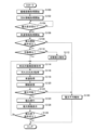
まず、車両10(ECU24)の電源がONされると、画像取得部38は、撮像部14を動作させ撮像画像の取得を開始し(S100)、逐次RAM24cの撮像画像格納部56の格納して行く。そして、汚れ情報取得部40は、撮像部14で撮像された撮像画像に対して、汚れ情報の取得を開始する(S102)。すなわち、撮像画像を、汚れ情報学習済みモデル格納部50から呼び出した汚れ情報学習済みモデルに順次入力して、汚れの有無および汚れが存在する場合、その汚れの大きさと位置を示す汚れ情報を取得する。 First, when the vehicle 10 (ECU 24) is powered on, the image acquisition unit 38 operates the imaging unit 14 to start acquisition of captured images (S100), and sequentially stores the captured images in the captured image storage unit 56 of the RAM 24c. go. Then, the stain information acquisition unit 40 starts acquiring stain information from the captured image captured by the imaging unit 14 (S102). That is, the captured images are sequentially input to the dirt information learned model called from the dirt information learned model storage unit 50, and if there is dirt, dirt information indicating the size and position of the dirt is acquired. do.

続いて、受付部36は、復元要求信号を受け付けているか否か確認する(S104のNo)。受付部36は、例えば、利用者が操作入力部20等を介して復元画像の生成を要求した場合、または汚れ情報取得部40が取得した汚れ情報に基づき汚れを検出した場合に、復元要求信号を受け付ける(S104のYes)。速度取得部42は、受付部36が復元要求信号を受け付けると、現在の車両10の車速の取得を開始する(S106)。そして、復元実行判定部44cは、現在の状況において、撮像画像を復元する復元開始条件が成立しているか否か判定する(S108)。具体的には、閾値変更部44c1は、汚れの大きさおよび車両10の車速に基づき、汚れによって隠蔽された領域の復元が可能か否かを判定する閾値を決定(変更)する。復元実行判定部44cは、復元対象の撮像画像の汚れの大きさが閾値変更部44c1で決定(変更)された閾値未満の場合、復元開始条件が成立したと判定し(S108のYes)、報知部46は、復元処理が手動復元モードで要求されたか否か判定する(S110)。復元処理が自動復元モードで要求された場合(S110のNo)、報知部46は、復元処理が自動で行われていることを利用者に報知する自動復元報知を実行する(S112)。例えば、表示装置16上で復元画像の表示を行うことを示すメッセージをROM24b等から読み出す。また、障害物検出モジュールや白線検出モジュール等に提供する復元実行フラグをONする。 Subsequently, the reception unit 36 confirms whether or not the restoration request signal is received (No in S104). For example, when the user requests generation of a restored image via the operation input unit 20 or the like, or when dirt is detected based on the dirt information acquired by the dirt information acquisition unit 40, the reception unit 36 outputs a restoration request signal. is accepted (Yes in S104). When the receiving unit 36 receives the restoration request signal, the speed obtaining unit 42 starts obtaining the current vehicle speed of the vehicle 10 (S106). Then, the restoration execution determination unit 44c determines whether or not the restoration start condition for restoring the captured image is satisfied in the current situation (S108). Specifically, the threshold changing unit 44c1 determines (changes) a threshold for determining whether or not a region hidden by dirt can be restored based on the degree of dirt and the vehicle speed of the vehicle 10. FIG. If the size of the dirt on the captured image to be restored is less than the threshold determined (changed) by the threshold changer 44c1, the restoration execution determination unit 44c determines that the restoration start condition is met (Yes in S108), and notifies. The unit 46 determines whether the restore process was requested in manual restore mode (S110). When the restoration process is requested in the automatic restoration mode (No in S110), the notification unit 46 executes automatic restoration notification to notify the user that the restoration process is being automatically performed (S112). For example, a message indicating that the restored image is to be displayed on the display device 16 is read from the ROM 24b or the like. Also, the restoration execution flag provided to the obstacle detection module, the white line detection module, etc. is turned ON.

続いて、復元処理部44は、RAM24cの撮像画像格納部56に格納した時系列の撮像画像から現時点における最新撮像画像76aおよび過去画像76bを含む時系列の複数の撮像画像76を取得する(S114)。続いて、復元実行判定部44cは最新撮像画像76aにおける汚れ78の大きさを汚れ情報取得部40から取得するとともに(S116)、速度取得部42から現在の車両10の車速を取得する(S118)。そして、閾値変更部44c1は、閾値データ格納部55から読み出した閾値マップを参照して、最新撮像画像76aの汚れ78で隠蔽された領域の復元が可能か否かを判定するための閾値を汚れ78の大きさおよび車速に基づき変更する(S120)。そして、復元実行判定部44cが最新撮像画像76aの復元が可能であると判定した場合(S122のYes)、つまり、復元条件が成立している場合、復元処理部44は、復元処理を実行する(S124)、つまり、第1復元処理部44aは、最新撮像画像76aおよび過去画像76bからなる時系列的に撮像された撮像画像76を、第1学習済みモデル格納部52から読み出した第1学習済みモデル64に入力し、第1復元画像80を生成する。続いて、第2復元処理部44bは、生成された第1復元画像80と第1復元画像80を生成する場合に用いた最新撮像画像76aとを、第2学習済みモデル格納部54から読み出した第2学習済みモデル74に入力し、第2復元画像84を生成する。そして、出力部48は、生成された第2復元画像84を表示装置16で表示する場合は、表示制御部24dに出力する。また、障害物検出処理や白線検出処理が実行中の場合は、障害物検出モジュールや白線検出モジュール等に第2復元画像84(復元画像データ)を出力する(S126)。 Subsequently, the restoration processing unit 44 acquires a plurality of time-series captured images 76 including the current latest captured image 76a and the past image 76b from the time-series captured images stored in the captured image storage unit 56 of the RAM 24c (S114). ). Subsequently, the restoration execution determination unit 44c acquires the size of the dirt 78 in the latest captured image 76a from the dirt information acquisition unit 40 (S116), and acquires the current vehicle speed of the vehicle 10 from the speed acquisition unit 42 (S118). . Then, the threshold change unit 44c1 refers to the threshold map read out from the threshold data storage unit 55, and sets the threshold for determining whether or not the region hidden by the dirt 78 in the latest captured image 76a can be restored. 78 and the vehicle speed (S120). Then, if the restoration execution determination unit 44c determines that the latest captured image 76a can be restored (Yes in S122), that is, if the restoration condition is satisfied, the restoration processing unit 44 executes restoration processing. (S124), that is, the first restoration processing unit 44a reads the captured images 76, which are the latest captured image 76a and the previous image 76b, captured in time series from the first trained model storage unit 52, and performs the first learning process. input to the finished model 64 to generate a first reconstructed image 80; Subsequently, the second restoration processing unit 44b reads the generated first restored image 80 and the latest captured image 76a used when generating the first restored image 80 from the second trained model storage unit 54. Input to the second trained model 74 to generate a second restored image 84 . Then, when displaying the generated second restored image 84 on the display device 16, the output unit 48 outputs it to the display control unit 24d. Also, when the obstacle detection process and the white line detection process are being executed, the second restored image 84 (restored image data) is output to the obstacle detection module, the white line detection module, etc. (S126).

そして、復元実行判定部44cは、受付部36が復元処理の終了を示す終了要求信号を受け取ったり、車両10(ECU24)の電源がOFFされたりする、復元終了条件が成立しているか否か確認する(S128)。復元終了条件が成立している場合(S128のYse)、このフローを終了する。なお、この場合、周辺監視部34は、撮像部14で撮像した未復元の撮像画像を表示装置16に表示するようにするとともに、障害物検出モジュールや白線検出モジュール等に未復元の撮像画像データを提供する旨の通知(復元フラグのOFF)を行う。また、復元終了条件が成立していない場合(S128のNo)、S114に移行し、復元処理部44のよる復元処理を継続する。 Then, the restoration execution determination unit 44c confirms whether or not a restoration end condition is satisfied, such as when the reception unit 36 receives an end request signal indicating the end of the restoration process, or when the power of the vehicle 10 (ECU 24) is turned off. (S128). If the restoration end condition is satisfied (Yes in S128), this flow is ended. In this case, the perimeter monitoring unit 34 displays the unrestored captured image captured by the imaging unit 14 on the display device 16, and displays the unrestored captured image data on the obstacle detection module, the white line detection module, and the like. is provided (restoration flag is turned OFF). If the restoration end condition is not satisfied (No in S128), the process proceeds to S114 and the restoration processing by the restoration processing unit 44 is continued.

また、S122において、汚れ78の大きさの変化や車速の変化により、最新撮像画像76aの汚れ78で隠蔽された領域の復元が十分に実行できないと判定された場合(S122のNo)、つまり、復元条件が不成立となって場合、復元不可であることを示すメッセージを表示装置16等を介して報知し(S130)、一旦このフローを終了する。また、S108において、復元開始条件が成立しない場合(S108のNo)、S130に移行して、復元不可報知を行い、このフローを一旦終了する。なお、図7に示すフローチャートは,一例であり、同様な撮像画像における汚れに隠蔽され領域の復元ができれば、処理の順番や内容を変更してもよい。 Further, in S122, if it is determined that the region hidden by the dirt 78 in the latest captured image 76a cannot be fully restored due to a change in the size of the dirt 78 or a change in the vehicle speed (No in S122), that is, If the restoration condition is not met, a message indicating that restoration is not possible is notified via the display device 16 or the like (S130), and this flow is temporarily terminated. Also, in S108, if the restoration start condition is not satisfied (No in S108), the process proceeds to S130, informing that restoration is not possible is performed, and this flow is temporarily terminated. Note that the flowchart shown in FIG. 7 is an example, and the order and contents of processing may be changed as long as an area hidden by dirt in a similar captured image can be restored.

このように本実施形態の周辺監視装置(周辺監視部34)によれば、車両の移動中に撮像された時系列的な複数の撮像画像を学習済みモデルに入力して、復元画像を生成するので、より実世界の環境状況に近い復元画像が提供できる。その結果、周辺監視のための提供情報の品質向上、周辺監視精度の向上が図れる。 As described above, according to the surroundings monitoring device (the surroundings monitoring unit 34) of the present embodiment, a plurality of time-series captured images captured while the vehicle is moving are input to the trained model to generate a restored image. Therefore, it is possible to provide a restored image that is closer to the environmental conditions in the real world. As a result, it is possible to improve the quality of information provided for monitoring the surroundings and improve the accuracy of monitoring the surroundings.

なお、上述した実施形態では、復元処理の実行の可否を汚れ78の大きさと車両10の車速により決定(変更)される閾値に基づいて判定したが、例えば、車両10の操舵角や加速度等を考慮して閾値を変更してもよい。例えば、舵角センサ28の検出値に基づき、車両10が方向を大きく変えていることが検出された場合を考える。この場合、汚れの大きさが大きい場合や車速が遅い場合でも、最新撮像画像76aで汚れ78により隠蔽されている領域でも時系列的に遡った過去画像76bでは、汚れ78で隠蔽されていな可能性が高まる。車両10が加速された場合も同様である。したがって、舵角情報や加速度情報を用いることにより、閾値の最適化が可能になり、より適切に復元処理を実行することができる。また、情報取得部30から取得可能な車両10の位置情報や車両10が存在する場所の天候情報を考慮して閾値を変更してもよい。例えば、激しい雨天で、撮像画像76上の雨滴の数が極端に多いと判定される場合、各汚れ(雨滴)の大きさが小さい場合でも、復元処理を非実行とするように閾値を変更してもよい。 In the above-described embodiment, whether or not the restoration process can be executed is determined based on the threshold determined (changed) according to the size of the dirt 78 and the vehicle speed of the vehicle 10. You may change a threshold considering. For example, consider a case where it is detected that the vehicle 10 is significantly changing its direction based on the detection value of the steering angle sensor 28 . In this case, even if the size of the dirt is large or the vehicle speed is slow, it is possible that even an area that is hidden by the dirt 78 in the latest captured image 76a is not hidden by the dirt 78 in the past image 76b that goes back in time series. sexuality increases. The same is true when the vehicle 10 is accelerated. Therefore, by using the steering angle information and the acceleration information, the threshold can be optimized, and the restoration process can be executed more appropriately. In addition, the threshold may be changed in consideration of the location information of the vehicle 10 that can be acquired from the information acquisition unit 30 and the weather information of the location where the vehicle 10 is present. For example, if it is determined that the number of raindrops on the captured image 76 is extremely large due to heavy rain, the threshold is changed so that the restoration process is not executed even if the size of each stain (raindrop) is small. may

また、上述した実施形態では、例えば、後方画像について、汚れが存在しないかのように復元した例を示したが、他の撮像画像、例えば、前方画像、右側方画像、左側方画像についても、同様な処理により復元処理を実行することが可能で、同様の効果を得ることができる。また、俯瞰画像等の合成画像に対しても本実施形態の復元処理が適用可能であり、同様の効果を得ることができる。この場合、復元対象の撮像画像や合成画像は、操作入力部20等により指定するようにしてもよいし、表示装置16に表示する画像や周辺監視で用いる画像データに応じて自動的に選択されるようにしてもよい。 Further, in the above-described embodiment, for example, the rear image is restored as if no dirt exists. Restoration processing can be executed by similar processing, and similar effects can be obtained. Also, the restoration processing of the present embodiment can be applied to a composite image such as a bird's-eye view image, and similar effects can be obtained. In this case, the captured image or synthesized image to be restored may be specified by the operation input unit 20 or the like, or may be automatically selected according to the image displayed on the display device 16 or the image data used for surrounding monitoring. You may do so.

本実施形態の周辺監視部34(CPU24a)で実行される復元処理のための周辺監視プログラムは、インストール可能な形式又は実行可能な形式のファイルでCD-ROM、フレキシブルディスク(FD)、CD-R、DVD(Digital Versatile Disk)等のコンピュータで読み取り可能な記録媒体に記録して提供するように構成してもよい。 A peripheral monitoring program for restoration processing executed by the peripheral monitoring unit 34 (CPU 24a) of the present embodiment is a file in an installable format or an executable format and can be downloaded from a CD-ROM, flexible disk (FD), or CD-R. , DVD (Digital Versatile Disk) or other computer-readable recording medium.

さらに、周辺監視プログラムを、インターネット等のネットワークに接続されたコンピュータ上に格納し、ネットワーク経由でダウンロードさせることにより提供するように構成してもよい。また、本実施形態で実行される周辺監視プログラムをインターネット等のネットワーク経由で提供または配布するように構成してもよい。 Furthermore, the perimeter monitoring program may be stored on a computer connected to a network such as the Internet and provided by being downloaded via the network. Further, the perimeter monitoring program executed in this embodiment may be configured to be provided or distributed via a network such as the Internet.

本発明の実施形態及び変形例を説明したが、これらの実施形態及び変形例は、例として提示したものであり、発明の範囲を限定することは意図していない。これら新規な実施形態は、その他の様々な形態で実施されることが可能であり、発明の要旨を逸脱しない範囲で、種々の省略、置き換え、変更を行うことができる。これら実施形態やその変形は、発明の範囲や要旨に含まれるとともに、特許請求の範囲に記載された発明とその均等の範囲に含まれる。 While embodiments and variations of the invention have been described, these embodiments and variations are provided by way of example and are not intended to limit the scope of the invention. These novel embodiments can be implemented in various other forms, and various omissions, replacements, and modifications can be made without departing from the scope of the invention. These embodiments and modifications thereof are included in the scope and gist of the invention, and are included in the scope of the invention described in the claims and equivalents thereof.

10…車両、14,14a,14b,14c,14d…撮像部、16…表示装置、24…ECU、24a…CPU、24b…ROM、24c…RAM、26…車輪速センサ、28…舵角センサ、30…情報取得部、34…周辺監視部、36…受付部、38…画像取得部、40…汚れ情報取得部、42…速度取得部、44…復元処理部、44a…第1復元処理部、44b…第2復元処理部、44c…復元実行判定部、44c1…閾値変更部、46…報知部、48…出力部、50…汚れ情報学習済みモデル格納部、52…第1学習済みモデル格納部、54…第2学習済みモデル格納部、55…閾値データ格納部、56…撮像画像格納部、58…第1学習用画像、60…第1学習用汚れ画像、62…学習用汚れ、64…第1学習済みモデル、66…第2学習用汚れ画像、66a…最新学習用汚れ画像、68…復元画像、70,82…不自然領域、72,78…汚れ、74…第2学習済みモデル、76…撮像画像、76a…最新撮像画像、76b…過去画像、80…第1復元画像、84…第2復元画像。 DESCRIPTION OF SYMBOLS 10... Vehicle 14, 14a, 14b, 14c, 14d... Imaging part 16... Display device 24... ECU, 24a... CPU, 24b... ROM, 24c... RAM, 26... Wheel speed sensor, 28... Steering angle sensor, 30... Information acquisition unit, 34... Surroundings monitoring unit, 36... Reception unit, 38... Image acquisition unit, 40... Dirt information acquisition unit, 42... Speed acquisition unit, 44... Restoration processing unit, 44a... First restoration processing unit, 44b... Second restoration processing unit 44c... Restoration execution determination unit 44c1... Threshold value change unit 46... Notification unit 48... Output unit 50... Dirt information learned model storage unit 52... First learned model storage unit , 54... Second learned model storage unit 55... Threshold data storage unit 56... Captured image storage unit 58... First learning image 60... First learning stain image 62... Learning stain 64... First learned model 66 Second learning dirt image 66a Latest learning dirt image 68 Restored image 70, 82 Unnatural area 72, 78 Dirt 74 Second learned model 76... picked-up image, 76a... latest picked-up image, 76b... past image, 80... first restored image, 84... second restored image.

Claims (4)

車両に備えられて前記車両の周囲を撮像可能な撮像部で前記車両が移動している際に時系列的に撮像される複数の撮像画像を取得する取得部と、
前記複数の撮像画像のうち最新の最新撮像画像に汚れが存在する場合に、学習用汚れが存在しない第1の学習用画像と、当該第1の学習用画像に前記学習用汚れが存在する、複数の第1の学習用汚れ画像と、の関係を機械学習した結果としての第1の学習済みモデルに、前記取得部によって時系列的に撮像された前記複数の撮像画像を入力して、第1復元画像を前記最新撮像画像において前記汚れにより隠蔽された領域を復元させた復元画像として生成する復元処理部と、
を備える、周辺監視装置。
an acquisition unit that acquires a plurality of captured images captured in time series while the vehicle is moving by an imaging unit that is provided in the vehicle and is capable of capturing images around the vehicle;
When dirt exists in the latest latest captured image among the plurality of captured images, a first learning image in which the learning dirt does not exist, and the learning dirt exists in the first learning image. inputting the plurality of captured images captured in time series by the acquisition unit into a first trained model as a result of machine learning of the relationship between the plurality of first learning dirt images, and 1 a restoration processing unit that generates a restored image as a restored image obtained by restoring a region hidden by the dirt in the latest captured image;
A perimeter monitoring device comprising:
前記復元処理部は、前記第1の学習済みモデルに、前記学習用汚れが存在する、複数の第2の学習用汚れ画像を入力して生成した前記復元画像と、当該復元画像を復元する際に利用した複数の前記第2の学習用汚れ画像のうち最新の最新学習用汚れ画像との関係を、機械学習した結果としての第2の学習済みモデルに、前記第1復元画像と、前記最新撮像画像とを入力して、第2復元画像を前記復元画像として復元する、請求項1に記載の周辺監視装置。 The restoration processing unit generates the restored image generated by inputting a plurality of second learning dirt images in which the learning dirt exists in the first trained model, and restores the restored image. The first restored image and the latest 2. The perimeter monitoring device according to claim 1, wherein a captured image is input and a second restored image is restored as said restored image. 前記復元処理部は、前記最新撮像画像に存在する前記汚れの大きさを示す汚れ情報を取得し、前記汚れ情報が示す汚れの大きさが、所定の閾値以上の場合、復元処理を非実行とする、請求項1または請求項2に記載の周辺監視装置。 The restoration processing unit acquires dirt information indicating the size of the dirt present in the latest captured image, and if the size of the dirt indicated by the dirt information is equal to or greater than a predetermined threshold, the restoration processing is not executed. 3. The perimeter monitoring device according to claim 1 or 2, wherein: 前記復元処理部は、前記取得部が前記撮像画像を取得したときの前記車両の速度情報を取得し、前記速度情報の示す車速に応じて、前記閾値を変更する、請求項3に記載の周辺監視装置。 4. The periphery according to claim 3, wherein the restoration processing unit acquires speed information of the vehicle when the acquisition unit acquires the captured image, and changes the threshold according to the vehicle speed indicated by the speed information. surveillance equipment.
JP2018210710A 2018-11-08 2018-11-08 Perimeter monitoring device Active JP7271908B2 (en)

Priority Applications (2)

Application Number Priority Date Filing Date Title
JP2018210710A JP7271908B2 (en) 2018-11-08 2018-11-08 Perimeter monitoring device
US16/676,584 US11393223B2 (en) 2018-11-08 2019-11-07 Periphery monitoring device

Applications Claiming Priority (1)

Application Number Priority Date Filing Date Title
JP2018210710A JP7271908B2 (en) 2018-11-08 2018-11-08 Perimeter monitoring device

Publications (2)

Publication Number Publication Date
JP2020077251A JP2020077251A (en) 2020-05-21
JP7271908B2 true JP7271908B2 (en) 2023-05-12

Family

ID=70552263

Family Applications (1)

Application Number Title Priority Date Filing Date
JP2018210710A Active JP7271908B2 (en) 2018-11-08 2018-11-08 Perimeter monitoring device

Country Status (2)

Country Link
US (1) US11393223B2 (en)
JP (1) JP7271908B2 (en)

Families Citing this family (5)

* Cited by examiner, † Cited by third party
Publication number Priority date Publication date Assignee Title
JP7156225B2 (en) * 2019-09-20 2022-10-19 株式会社デンソーテン Attached matter detection device and attached matter detection method
TWI767300B (en) * 2020-08-18 2022-06-11 廣達電腦股份有限公司 Computing device and method of removing raindrops in video images
JP7710865B2 (en) * 2021-03-18 2025-07-22 ダイハツ工業株式会社 Data set creation method for image processing device, and image processing device
CN113177892B (en) * 2021-04-29 2024-11-01 北京百度网讯科技有限公司 Method, device, medium and program product for generating image restoration model
CN120858373A (en) * 2023-03-10 2025-10-28 索尼半导体解决方案公司 Information processing device and information processing method

Citations (2)

* Cited by examiner, † Cited by third party
Publication number Priority date Publication date Assignee Title
JP2017092622A (en) 2015-11-06 2017-05-25 クラリオン株式会社 Image processing system
WO2018197984A1 (en) 2017-04-28 2018-11-01 株式会社半導体エネルギー研究所 Display system and mobile body

Family Cites Families (8)

* Cited by examiner, † Cited by third party
Publication number Priority date Publication date Assignee Title
JP4326999B2 (en) * 2003-08-12 2009-09-09 株式会社日立製作所 Image processing system
JP5887219B2 (en) * 2012-07-03 2016-03-16 クラリオン株式会社 Lane departure warning device
JP6117634B2 (en) * 2012-07-03 2017-04-19 クラリオン株式会社 Lens adhesion detection apparatus, lens adhesion detection method, and vehicle system
US9445057B2 (en) * 2013-02-20 2016-09-13 Magna Electronics Inc. Vehicle vision system with dirt detection
EP2899692B1 (en) * 2014-01-28 2019-09-04 Honda Research Institute Europe GmbH Method, system, imaging device, movable device and program product for detecting static elements in video and image sources
JP6246014B2 (en) * 2014-02-18 2017-12-13 クラリオン株式会社 Exterior recognition system, vehicle, and camera dirt detection method
JP6576887B2 (en) * 2016-08-09 2019-09-18 クラリオン株式会社 In-vehicle device
US10339812B2 (en) * 2017-03-02 2019-07-02 Denso International America, Inc. Surrounding view camera blockage detection

Patent Citations (2)

* Cited by examiner, † Cited by third party
Publication number Priority date Publication date Assignee Title
JP2017092622A (en) 2015-11-06 2017-05-25 クラリオン株式会社 Image processing system
WO2018197984A1 (en) 2017-04-28 2018-11-01 株式会社半導体エネルギー研究所 Display system and mobile body

Non-Patent Citations (2)

* Cited by examiner, † Cited by third party
Title
Bartosz Zielinski et al.,"Cascade context encoder for improved inpainting",[online],2018年03月11日,arXiv:1803.04033v1,<https://arxiv.org/pdf/1803.04033.pdf>
David Eigen et al.,"Restoring an Image Taken through a Window Covered with Dirt or Rain",2013 IEEE International Conference on Computer Vision,IEEE,2013年,pp.633-640,<https://ieeexplore.ieee.org/stamp/stamp.jsp?tp=&arnumber=6751188>

Also Published As

Publication number Publication date
US11393223B2 (en) 2022-07-19
US20200151466A1 (en) 2020-05-14
JP2020077251A (en) 2020-05-21

Similar Documents

Publication Publication Date Title
JP7271908B2 (en) Perimeter monitoring device
US9902323B2 (en) Periphery surveillance apparatus and program
JP7200572B2 (en) Deposit detection device
JP2016097896A (en) Image display control device
JP2020043400A (en) Periphery monitoring device
CN112581381A (en) Periphery monitoring device and periphery monitoring method
JP5680436B2 (en) Foreign matter adhesion determination device for in-vehicle camera lens
US11383642B2 (en) Display control apparatus
JP7395913B2 (en) object detection device
CN111612701A (en) Peripheral monitoring device
CN108886602A (en) information processing device
US11017245B2 (en) Parking assist apparatus
WO2017122654A1 (en) Drive assist device and drive assist method
JP4687411B2 (en) Vehicle peripheral image processing apparatus and program
JP2016189576A (en) Image display control device
JP2013244852A (en) Device, method and program of parking support
CN107077715B (en) Vehicle surrounding image display device and vehicle surrounding image display method
JP2019153932A (en) Soil notification device
CN112349091A (en) Specific area detecting device
JP7454177B2 (en) Peripheral monitoring device and program
JP7137356B2 (en) In-vehicle failure detection device and failure detection method
JP5529058B2 (en) Three-dimensional object detection device and three-dimensional object detection method
JP6965563B2 (en) Peripheral monitoring device
JP2025044748A (en) Object detection device
JP2025051210A (en) Object detection device

Legal Events

Date Code Title Description
A621 Written request for application examination

Free format text: JAPANESE INTERMEDIATE CODE: A621

Effective date: 20210921

A977 Report on retrieval

Free format text: JAPANESE INTERMEDIATE CODE: A971007

Effective date: 20220824

A131 Notification of reasons for refusal

Free format text: JAPANESE INTERMEDIATE CODE: A131

Effective date: 20221004

A521 Request for written amendment filed

Free format text: JAPANESE INTERMEDIATE CODE: A523

Effective date: 20221202

TRDD Decision of grant or rejection written
A01 Written decision to grant a patent or to grant a registration (utility model)

Free format text: JAPANESE INTERMEDIATE CODE: A01

Effective date: 20230328

A61 First payment of annual fees (during grant procedure)

Free format text: JAPANESE INTERMEDIATE CODE: A61

Effective date: 20230410

R150 Certificate of patent or registration of utility model

Ref document number: 7271908

Country of ref document: JP

Free format text: JAPANESE INTERMEDIATE CODE: R150