JP4323610B2 - Image data management apparatus and control method thereof - Google Patents
Image data management apparatus and control method thereof Download PDFInfo
- Publication number
- JP4323610B2 JP4323610B2 JP07686399A JP7686399A JP4323610B2 JP 4323610 B2 JP4323610 B2 JP 4323610B2 JP 07686399 A JP07686399 A JP 07686399A JP 7686399 A JP7686399 A JP 7686399A JP 4323610 B2 JP4323610 B2 JP 4323610B2
- Authority
- JP
- Japan
- Prior art keywords
- image data
- setting
- unit
- group
- data management
- Prior art date
- Legal status (The legal status is an assumption and is not a legal conclusion. Google has not performed a legal analysis and makes no representation as to the accuracy of the status listed.)
- Expired - Fee Related
Links
Images


Landscapes
- Management Or Editing Of Information On Record Carriers (AREA)
- Details Of Television Systems (AREA)
- Studio Devices (AREA)
- Two-Way Televisions, Distribution Of Moving Picture Or The Like (AREA)
Description
【0001】
【発明の属する技術分野】
本発明は、PC(パーソナルコンピュータ)等の画像管理装置に画像データを転送する、デジタルカメラ等の画像データ転送装置及び受信した画像データを効率よく管理、保存する画像データ管理装置及びその制御方法に関する。
【0002】
【従来の技術】
従来から、デジタルカメラなどの画像記録装置と、PC等の画像データを記憶・管理することが可能な画像記憶管理装置とを接続し、画像記録装置内の画像データを画像記憶管理装置に転送し、そこで画像データを記憶・管理するシステムがある。
【0003】
【発明が解決しようとする課題】
しかしながら、上記従来の技術においては、以下のような問題点がある。
まず、ユーザはデジタルカメラとPCを接続し、デジタルカメラをデータ転送可能なモードにし、かつ、その状態で、PC上で、デジタルカメラと接続しデータ転送するためのアプリケーションを起動するという手間が必要があった。その上、アプリケーション側では、取得したデータの管理方法、例えば、ファイル名やフォルダ名をその都度、指定する必要があった。
【0004】
本発明の目的は、従来必要であった、画像データ転送のためのアプリケーションの起動、転送指示、ファイル名の付与などが不要な画像データ転送装置を提供することにある。
また、本発明の別の目的は、受信した画像データを所定の条件で自動的に分類、記憶することが可能な画像データ管理装置を提供することにある。
【0005】
【課題を解決するための手段】
すなわち、本発明の要旨は、外部装置と通信可能な画像データ管理装置であって、外部装置から、画像データを受信する受信手段と、ユーザによる操作に応じて、受信手段により受信する画像データの保存先を設定する設定手段と、受信手段により受信した画像データの撮影日時に基づいて、画像データを管理するためのグループを生成する生成手段と、設定手段により設定された保存先に保存された画像データをさらに、生成手段により生成されたグループに基づき管理する管理手段とを有し、設定手段はさらに、ユーザによる操作に応じて生成手段が生成するグループの単位を設定することを特徴とする画像データ管理装置に存する。
【0006】
また、本発明の別の要旨は、外部装置と通信可能であり、外部装置から画像データを受信するための受信手段を有する画像データ管理装置の制御方法であって、ユーザによる操作に応じて、受信手段により受信する画像データの保存先を設定する設定ステップと、受信手段により受信した画像データの撮影日時に基づいて、画像データを管理するためのグループを生成する生成ステップと、設定ステップにおいて設定された保存先に保存された画像データを、さらに、生成ステップにおいて生成されたグループに基づき管理する管理ステップとを有し、設定ステップではさらに、ユーザによる操作に応じて生成ステップで生成するグループの単位を設定することを特徴とする画像データ管理装置の制御方法に存する。
【0008】
また、本発明の別の要旨は、コンピュータを本発明の画像データ管理装置の各手段として機能させるためのプログラムを記録したコンピュータ読み取り可能な記録媒体に存する。
【0009】
【発明の実施の形態】
以下、図面を参照して本発明の好ましい実施形態について説明する。
(画像データ管理システムの構成)
図1は、本発明に係る画像データ管理システムを実施可能な装置構成を模式的示す図である。
【0010】
図1において、301は例えば汎用のパーソナルコンピュータであるコンピュータ本体、302はコンピュータ本体301に接続されたディスプレー、303は代表的なポインティングデバイスであるマウス、304はマウスボタン、305はキーボードである。さらに、307は、コンピュータ本体301に接続可能なデジタルカメラであり、これは306の双方向シリアルインターフェースやUSB(ユニバーサル・シリアル・バス)等のデータ転送可能な汎用インターフェースによって接続されている。
【0011】
図2は本実施形態に係るハードウェアとソフトウェアの構成及びその相互関係を示す図である。図2において509はハードウェアであり、505はハードウェア509の上で動作するオペレーティングシステム(OS)であり、504はOS505の上で動作するアプリケーションソフトウェアである。なお図2において、ハードウェア509とOS505の構成要件として当然含まれるが本実施形態を説明する上で直接必要としないものに関しては図示していない。そのような図示していない構成要件の例としてハードウェアではCPU、メモリ、OSとしてはメモリ管理システム等がある。
【0012】
図2において515はファイルやデータを格納するハードディスク、508はOSを構成するファイルシステムでありアプリケーションソフトウェアがハードウェアを直接制御することなくファイルの入出力が行えるようにする機能がある。514はファイルシステム508がハードディスク515の読み書きを行うためのディスクI/Oインターフェースである。507はOSを構成する描画管理システムであリアプリケーションソフトウェアがハードウェアを直接制御することなく描画が行えるようにする機能がある。
【0013】
513は描画管理システム507がディスプレー302に描画を行うためのビデオインターフェースである。506はOSを構成する入力デバイス管理システムであり、アプリケーションソフトウェアがハードウェアを直接制御することなくユーザーの入力を受け取ることができるようにする機能がある。この中には、USB機器を使用するときのホストとなるUSBホストシステムも含まれる。
【0014】
510は入力デバイス管理システム506がキーボード305の入力を受け取るためのキーボードインターフェース、マウスインターフェース512は入力デバイス管理システム506がマウス303からの入力を受け取ることができるようにするためのマウスインターフェースである。さらに、デジタルカメラ307は、516の双方向シリアルインターフェースもしくはUSBインターフェース等に接続され、506入力デバイス管理システムを通して、画像データ等のやりとりを行うことができる。521入出力デバイスコマンド監視システムはカメラ等の外部デバイスから発行されるコマンドを監視し、コマンドの種類によりあらかじめ設定されている、そのコマンドに関連づけられた処理を行う。
【0015】
501はデジタルカメラホストアプリケーションであり、502は画像データを作成日付や撮影日付、キーワード等で管理するためのデータ管理手段である。503は管理されている画像データを表示するデータ表示手段である。520は新たに登録されるデータの属性を自動判別し、データをアプリケーションに登録するデータ登録手段である。
【0016】
本システムでは、デジタルカメラホストアプリケーション501により、デジタルカメラとのデータ転送を行う。そして、転送された画像データはデータ登録手段520によりコンピュータ本体301のハードディスク515に記憶される。
【0017】
(デジタルカメラの構成)
図3にデジタルカメラ307の構成を示すブロック図を示す。なお、図3において、構成要件として当然含まれるが本発明の実施形態を説明する上で直接必要としないものに関しては図示していない。
【0018】
図3において、撮像ユニット401はレンズやCCD、画像処理装置を含み、撮影した画像を画像データ(例えばJPEGデータ)として出力する。また、撮影した画像の縮小画像であるサムネール画像データも同時に生成する。本システムにおけるデジタルカメラでは、画像を撮影するほかに、音声を録音でき、録音ユニット402により、録音データ(例えばWAVE形式データ)として出力される。
【0019】
補助記憶装置403は撮像ユニット401や録音ユニット402からのデータをファイルとして保存するためのものであり、本実施形態では取り外し可能な記録媒体としてコンパクトフラッシュメモリーカードを用いている。404はデジタルカメラとコンピュータを接続するときのインターフェースで、図2におけるUSBインターフェースとUSBケーブルを用いて接続される。コントロールユニット405はデジタルカメラ307全体の動作を制御するためのものである。
【0020】
406は転送ボタンであり、本実施形態では、このボタンが押されると画像管理装置であるコンピュータ本体301への自動画像データ転送が開始される。407は表示ユニットであり、デジタルカメラに設けられた液晶パネル等の表示画面上に、撮像ユニットからの画像データを表示したり、また、デジタルカメラの設定を行う為のメニューを表示したりする。
【0021】
図4に本実施形態におけるデジタルカメラ307の外観図を示す。3071はメニューボタンで、このボタンが押されると表示画面3070にカメラの各種設定を行うためのメニューが表示される。ユーザーは操作ボタン3072を操作することにより、デジタルカメラ307の設定を変更することが出来る。また、カメラがコンピュータ本体301に接続された状態で転送ボタン406が押されると、後述する自動転送が開始される。
【0022】
(デジタルカメラ画像データの転送処理)
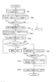
次に、本実施形態における、デジタルカメラ307とコンピュータ本体301との間で行われるデータ転送について説明する。まず、コンピュータ本体301とデジタルカメラ307との接続が確立され、自動転送を行うまでの動作を図5を用いて説明する。図5は、データ転送動作を説明するフローチャートである。
【0023】
上述の通り、本実施形態における画像データ管理システムでは、汎用的なインターフェースであるUSBをデジタルカメラとコンピュータ本体301とのインターフェースとして用いているものとする。まず、カメラとコンピュータ本体301とがUSBケーブルを用いて接続されると、OS505の入力デバイス管理システム506が接続を検出する。これで、コンピュータ本体301では、USBクライアントとして、デジタルカメラが接続されたことが認識される(ステップS41)。
【0024】
次いで、入力デバイス管理システム506に含まれるUSBホストがUSBクライアントであるデジタルカメラにコマンドを発行する。このコマンドを受信することにより、デジタルカメラではUSBクライアントとしてコンピュータ本体301に接続されたことを認識し、データ転送可能なモードになる(ステップS42)。
【0025】
デジタルカメラ307はコンピュータ本体301に接続されたことを認識すると、カメラ内部に保持した設定項目のうち、自動転送モードの設定を調べる(ステップS43)。このモードは、図6に示す、カメラの表示画面3070に表示される自動転送設定メニュー画面3080もしくは図7に示す、デジタルカメラホストアプリケーション501のメニュー(図示せず)を選択することにより表示されるカメラ設定画面3081で設定されるもので、本実施形態においては設定される自動転送モードとして「PC(コンピュータ本体)301との接続と同時に全ての画像を転送する」モード(ラジオボタン3084又は3087)と「転送ボタンが押されると全ての画像を転送する」モード(ラジオボタン3085又は3088)の2つがある。
【0026】
モードの設定は排他的であり、いずれか一方のみを選択できる。カメラ307の設定画面3080にはモード選択用のラジオボタン3087、3088の他に、カメラ307内の画像データを転送した後削除するか否かを設定するチェックボックス3089が設けられている。設定画面3080を閉じると、その時点での設定がカメラに設定される。
【0027】
なお、図7のカメラ設定画面3081はカメラ307とコンピュータ本体301が接続され通信可能な状態のときのみ表示可能なように、ホストアプリケーション501が制御している。具体的には、カメラ設定画面を表示するためのメニューをカメラ307が接続されて通信可能な状態である場合にのみ有効としている。カメラ設定画面3081には、自動転送モードの設定を行うラジオボタン3084、3085以外に、カメラの所有者名を設定する所有者設定領域3082、カメラ307内部の時計を設定する日時設定領域3083、チェックボックス3086と、3つのボタン3090〜3092が設けられている。チェックボックス3086はカメラ側の設定画面3080のチェックボックス3089と同一の機能を有する。
【0028】
OKボタン3090または、更新ボタン3092がマウス303またはキーボード305により選択され、押下(マウスボタン304のクリック又はキーボードのエンターキーなど所定キーの押下を意味する。以下同様の意味で使用する)されると、カメラ設定画面3081の各領域(ラジオボタン、チェックボックスを含む。以下の説明においても同様の意味で使用する)に設定された値がカメラ307に転送され、内部の不揮発性メモリ等に設定される。
【0029】
図5のステップS43では、デジタルカメラ307がこの自動転送モード設定を調べ、「コンピュータ本体301との接続と同時に全ての画像を転送する」モードに設定されている場合はステップS44へ進み自動転送の処理を行う。一方、「転送ボタンが押されると全ての画像を転送する」モードに設定されている場合は、処理を終了する。
【0030】
ステップS44では、デジタルカメラ307がコンピュータ本体301に対して、データ転送開始要求コマンドを発行する。コンピュータ本体301では、OS505に含まれる入出力デバイスコマンド監視システム521が同じくOS505に含まれる入力デバイス管理システム506を介して受信し、このコマンドにより、あらかじめ設定されているデジタルカメラ・ホストアプリケーションを501を起動する。デジタルカメラ307は、コマンドを発行すると、アプリケーションからのコマンド発行を待つ(ステップS45)。
【0031】
デジタルカメラ307のコマンドに対応して起動されたホストアプリケーション501は、正常に起動しデータ受信の準備が出来ると、デジタルカメラ307に対して、送信許可コマンドを発行する。デジタルカメラ307は、送信許可コマンドを受信するとステップS46へ移行し、液晶表示画面3070上に自動転送処理中であることを示すメッセージ(例えば‘自動転送中’)を表示する。
【0032】
ステップS47では、カメラ内にコンピュータ本体301へ未転送の画像データがあるかを調べる。もしまだコンピュータ本体301に転送されていない画像データがある場合は、ステップS48においてコンピュータ本体301へのデータ転送を行う。この時、コンピュータ本体301上で起動されたデジタルカメラホストアプリケーション501では、デジタルカメラからの画像データを自動的に管理・保存する。ホストアプリケーションによる画像データの管理・保存の詳細については後で詳述する。
【0033】
全ての画像データが転送されるとステップS47からステップS49へ移行し、デジタルカメラ307は転送終了コマンドをコンピュータ本体301に送る。ステップS410では、自動転送したデータを自動的にカメラ内の補助記憶装置403から削除するかを決定する。これは、前述したカメラの自動転送設定メニュー画面3080、もしくは図7に示す、アプリケーションのメニューから起動されるカメラ設定画面3081のチェックボックス3089又は3086で設定される項目である。
【0034】
設定内容のチェックの結果、自動転送された画像を自動的にデジタルカメラ内の補助記憶装置403から削除するモードに設定されていない場合はステップS412へ移行し、設定されている場合はステップS411にて、カメラ内の補助記憶装置403から自動転送された画像を削除する。これにより、カメラ内の補助記憶装置の空き容量を自動的に回復する。ステップS412では、カメラの表示画面3070上に転送処理の終了を示すメッセージ(例えば‘自動転送終了’)を表示し、一連の処理が終了したことを表示する。
【0035】
また、図5のステップS44以下の処理は、デジタルカメラ本体に設けられた、転送ボタン406が押されることによっても行われる。この場合は、図4に示すカメラ背面の転送ボタン406が押されると図5のステップS44が実行され、カメラがデータ転送開始要求コマンドをホストコンピュータ本体301に対して発行することにより、ステップS44以降の一連の処理が行われる。
【0036】
(デジタルカメラホストアプリケーションの動作)
次に、本実施形態における、コンピュータ本体301上で動作する、画像を管理・保存するホストアプリケーション501の説明を行う。
【0037】
本実施形態による画像管理・保存アプリケーションの動作として、カメラから取得した画像を自動的にその撮影日付もしくは作成日付毎にフォルダで分割して保存する動作を図8のフローチャートを用いて説明する。
【0038】
例えば、前述の自動転送処理において説明したカメラからの自動転送処理開始要求コマンドに対応して、送信許可コマンドをカメラに対して発行(ステップS51)し、カメラから送られてくるデータを受信する(ステップS52)。次にステップS53で送られてきたデータが自動転送終了コマンドかを判別する。自動転送終了コマンドで無い場合は、送信されてきたデータは画像データであると判断して、ステップS54にて、画像データに含まれる属性情報から撮影日時が検出される。
【0039】
本実施形態におけるシステムでは、撮影日時はデジタルカメラにより撮影されたときに自動的に画像データの付帯情報としてデータに含まれ、ホストアプリケーション501においてもデータ中の撮影日時データの位置を認識しているものとする。次にステップS55で、ステップS54で得られた撮影日時に対応したフォルダ名を決定する。すなわち、撮影日時に対応したフォルダ名のフォルダが、あらかじめ設定されている自動格納用のフォルダ内に存在するか否かを調べ、存在しない場合は、あらかじめ定めたフォーマットに従ったフォルダ名で新規フォルダを作成する。本実施形態では、撮影日時が1998年6月29日の画像の場合、その日付をあらわす数値より、フォルダ名は‘19980629’とする。
【0040】
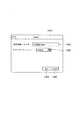
自動格納用のフォルダは、例えばホストアプリケーションのオプション設定画面において設定される。オプション設定画面の例を図9に示す。オプション設定画面1201は、受信したデータの自動格納先(フォルダ)を指定する自動格納フォルダ指定領域1202と、格納する際のデータフォーマットを選択するファイルフォーマット選択領域1203とを有している。また、OKボタン1204及びキャンセルボタン1205が設けられている。自動格納フォルダ指定領域1202は、自動格納先をディレクトリ等の形で入力して指定する領域である。また、ファイルフォーマット選択領域1203は自動格納するファイルの形式を選択して指定するプルダウンメニューである。図9では格納先として”C:¥MyImage”が、ファイルフォーマットとしてJPEGフォーマットが指定されている状態を示す。
【0041】
これら2つの領域で指定された内容は、OKボタン1204の押下によりホストアプリケーション501が使用する設定ファイルなどに保存される。キャンセルボタン1205が押下された場合には、設定内容が変更されることなくオプション設定画面1201が閉じられる。ホストアプリケーション501の最初の起動時など、自動格納フォルダの設定がなされていない状態で転送処理が行われる場合に、転送処理開始前にオプション設定画面1201を表示し、ユーザに設定させるようにしてもよい。
【0042】
図8に戻って、ステップS56では、ステップS55において見つけた(あるいは新規に作成した)フォルダ内を検索し、すでにあるファイル名と重ならない、ユニークなファイル名を決定する。本実施形態では、ファイル名を8桁の0からはじまる一連の数値であらわすことにし、新たなファイルを追加する場合は、追加するファイルのファイル名をあらわす数値が、そのフォルダにすでに含まれているファイルのファイル名をあらわす数値の中で最大となるように設定される。例えば、フォルダ‘19980629’内にファイル名がそれぞれ‘00000001.jpg’‘00000002.jpg’という2つのファイルが既に存在していた場合、新しく追加されるファイルのファイル名は‘00000003.jpg’となる。ファイル名の拡張子(.jpg)は図9に示したオプション設定画面1201のファイルフォーマット選択領域1203で指定されたファイルフォーマットに応じて自動的に付加される。
【0043】
ステップS57では、以上の処理により決定されたフォルダとファイル名を用いて、デジタルカメラからの入力データをファイルとしてコンピュータ本体301の記憶装置(例えばハードディスク515)に格納する。
【0044】
以上説明した構成により、デジタルカメラ307を画像データ管理システムに接続するだけで、画像データの転送及び管理、保存までが自動的に行われる。そのため、従来必要だったデジタルカメラホストアプリケーションの起動、画像データ転送指示、個々の受信データに対するファイル名付与等の動作が不要となり、非常に使い勝手がよい。
【0045】
(第2の実施形態)
次に本発明の第2の実施形態として、デジタルカメラホストアプリケーション501が、受信した画像データを自動的にその撮影日付もしくは作成日付毎にグループに分類し管理・登録する場合の動作について説明する。
【0046】
まず、本実施形態におけるアプリケーション501のデータ管理方法について図10を用いて説明する。本実施形態では、複数の画像データを含めることができる‘アルバム’を構築し、それらを図10に示すようなアルバム管理テーブルで管理する。アルバム管理テーブル700は各アルバム701〜703のアルバム名、また、アルバムに含まれる画像の情報を管理するアイテム管理テーブルへのポインタを保持している。アイテム管理テーブル704〜706は各アルバム毎に作成されるもので、アルバムに含まれる画像の格納場所と撮影日時を保持している。アルバム管理テーブル及び対応するアイテム管理テーブルは、画像データ管理システムが有する記憶装置(ハードディスク515等)に記憶されている。
【0047】
各アルバムに含まれる画像データの表示は、ディスプレイ302上にアルバム毎のウィンドウが作成され、各アルバムが含んでいる画像データを縮小画像と撮影日時との組み合わせて行う。図11には、アルバム701及び702に対応するウィンドウ802及び803がデジタルカメラホストアプリケーション501のウィンドウ801内に表示され、ウィンドウ802及び803には対応するアイテム管理テーブル704及び705に記載されている各画像データの縮小画像(サムネイル)と、その撮影時間が表示されている状態を示す。
【0048】
(アルバムへの自動登録動作)
次に、デジタルカメラ307から受信した画像データを自動的にアルバムに登録する動作について、図12のフローチャートを用いて説明する。
【0049】
まず、第1の実施形態と同様に、ステップS91で送信許可コマンドをカメラに対して発行し、ステップS92でカメラから送られてくるデータを受信する。次にステップS93で送られてきたデータが自動転送終了コマンドかを判別する。自動転送終了コマンドでは無い場合、送信されてきたデータは画像データとして、ステップS94で、画像データをあらかじめ指定されている自動格納フォルダに保存する。
【0050】
自動格納用のフォルダは、例えばホストアプリケーションのオプション設定画面において設定される。オプション設定画面の例を図13に示す。オプション設定画面1001は、アルバムを日毎に作成するか、月毎に作成するかを指定するラジオボタン1006及び1007と、受信したデータの自動格納先(フォルダ)を指定する自動格納フォルダ指定領域1002及び格納する際のデータフォーマットを選択するファイルフォーマット選択領域1003とを有している。また、オプション設定画面1001にはOKボタン1004及びキャンセルボタン1005が設けられている。
【0051】
ラジオボタン1006及び1007は、互いに排他的な選択を許し、ラジオボタン1006が選択された場合には撮影日ごと、ラジオボタン1007が選択された場合には撮影月毎にアルバムが自動作成される。自動格納フォルダ指定領域1002は、自動格納先をディレクトリ等の形で入力して指定する領域である。また、ファイルフォーマット選択領域1003は自動格納するファイルの形式を選択して指定するプルダウンメニューである。図13では格納先として”C:¥MyImage”が、ファイルフォーマットとしてJPEGフォーマットが指定されている状態を示す。
【0052】
これら2つの領域で指定された内容は、OKボタン1004の押下によりホストアプリケーション501が使用する設定ファイルなどに保存される。キャンセルボタン1005が押下された場合には、設定内容が変更されることなくオプション設定画面1001が閉じられる。ホストアプリケーション501の最初の起動時など、自動格納フォルダの設定がなされていない状態で転送処理が行われる場合に、転送処理開始前にオプション設定画面1001を表示し、ユーザに設定させるようにしてもよい。
【0053】
本実施形態においても自動格納時のファイル名は、第1の実施形態と同様のルールで付与される。すなわち、指定されているフォルダに含まれるファイル名より大きい数の下から順に用いて作成される。拡張子についても同様である。
受信したデータを格納したら、ステップS95で、画像データに含まれている付帯情報から、撮影日時を抽出する。
【0054】
ステップS96では、ステップS95で得られた撮影日時に相当するアルバム名のアルバムをアルバム管理テーブルから検索する。もし、相当するアルバムがアルバム管理テーブルに含まれていない場合は、新たにアルバムを作成する。アルバムを新規に作成する際には、上述のオプション設定画面1001のラジオボタン1006または1007で指定した単位でアルバムが作成される。すなわち、画像データの撮影日時が19980629(1998年6月29日)の場合、日毎(ラジオボタン1006)が選択されていればアルバム名”19980629”、月毎(ラジオボタン1007)が選択されていればアルバム名”199806”のアルバムが作成される。また、格納先のアルバムをさがす場合も、月毎の作成と設定されている場合には、その月のアルバムを検索する。
【0055】
ステップS97では、ステップS96で検索した、あるいは作成したアルバムに相当するアイテム管理テーブルにアイテムを追加し、ステップS94で格納したファイルへのパス名(格納場所及びファイル名)と撮影日時を登録する。
【0056】
本実施形態によれば、受信データの実体は記憶装置に順次記憶し、その付帯情報によって分類したテーブルを作成することによって、例えば日時以外の付帯情報によって分類するなど分類の基準を変える場合も、画像データを移動することなく、テーブルを作り替えるだけでよいため、柔軟性に富んだ管理が実現できる。
【0057】
(第3の実施形態)
次に本発明の第3の実施形態として、デジタルカメラホストアプリケーション501が、デジタルカメラ内の記憶装置のフォルダ構造(ファイルの階層構造)を維持したまま、画像データを転送する場合の動作について図14のフローチャートを用いて説明する。
【0058】
まず、第1の実施形態と同様に、ステップS31で送信許可コマンドをカメラに対して発行し、ステップS32でカメラから送られてくるデータを受信する。次にステップS33で送られてきたデータが自動転送終了コマンドかを判別する。自動転送終了コマンドで無い場合はステップS34に進み、カメラの記憶装置で格納されていたときのパス及びファイル名を調べる。ここで、カメラでのパス及びファイル名は、データの付帯情報として格納されているものとする。
【0059】
次にステップS35において、画像データ管理システムに格納するためのパス名を決定する。これは、図15に示すデジタルカメラホストアプリケーションのオプション設定画面1700での自動格納フォルダ設定領域1701の設定値とカメラ内でのパス名、ファイル名とを基に決められるもので、オプション設定画面1700の自動格納フォルダ設定領域1701の設定値と、カメラ内でのパス名のうち画像ルートフォルダ以下のものとをつなぎ合わされて作られる。
【0060】
ただし、オプション設定画面1700の“画像ルートフォルダ名は無視する”オプション1703が設定されているときは、設定した自動格納フォルダー名と、カメラ内のパス名から画像ルートフォルダ名を削除したものとをつなぎ合わせて決定される。なお、画像ルートフォルダとは、カメラの記憶装置のルート(最上位)フォルダ直下にあるフォルダで、カメラで撮影された画像はそのフォルダ内にのみ所定の方法で格納されるように設定されている。
【0061】
例えば、カメラ内でのパス名が“\DC97\CTG_0000\Aut_0001.jpg”の画像データファイルがあり、自動格納フォルダとして“C:\MyImage”が設定されている場合、ステップS35で決定されるパス名は“C:\MyImage\DC97\CTG_0000\Aut_0001.jpg”となる。なお、これは、“画像ルートフォルダ名は無視する”オプション1703が設定されていない場合で、設定されている場合はカメラ内でのパス名の内、画像ルートフォルダである“\DC97”より下の部分のみが使われ、“C:\MyImage\CTG_0000\Aut_0001.jpg”となる。
【0062】
オプション設定画面1700にはさらに、ファイルフォーマット選択領域1702と、OKボタン1704及びキャンセルボタン1705が設けられている。これらはそれぞれ図9に示したオプション設定画面1201における1203、1204及び1205と同一の機能を有するため、説明は省略する。
【0063】
また、自動格納フォルダ設定領域1701には参照ボタン1706が設けられており、このボタンを押下することにより、グラフィカルインターフェースを用いて自動格納フォルダを指定することができる。
【0064】
次に、ステップS36では、ステップS35で決定したパス名及びファイル名のファイルが既に存在しているかを調べる。ファイルが既に存在していた場合はステップS37に処理を移し、図16に示す警告ダイアログ画面を表示してユーザの指示を待つ。警告ダイアログ1800には、オプション設定画面1700における自動格納フォルダ設定領域1701と同じ機能を有する自動格納フォルダ指定領域1801と、同画面のボタン1704及び1705にそれぞれ対応するOKボタン1803、キャンセルボタン1804が設けられている。ダイアログ1800にはオプション設定画面1700と異なり、ファイル名を直接指定するためのファイル名指定領域1802が設けられている。
【0065】
OKボタン1803が押下された時点で領域1801および1802に指定されたフォルダ名及び/又はファイル名が最終的なフォルダ名、ファイル名になる。変更せずにOKボタン1803又はキャンセルボタン1804を押下した場合には、既存ファイルへの上書きを指示したと見なされる。
【0066】
ステップS38では、ステップS35で求めたパス名及びファイル名、もしくは、ステップS37で指定されたパス名、ファイル名で、転送されてきたファイルを保存する。
【0067】
以上の処理により、例えば、図17(a)に示すようなフォルダ構造で、デジタルカメラ307内の補助記憶装置403に画像ファイルが格納されている場合、図17(b)に示すように、自動格納フォルダ指定領域1701に指定されている画像データ管理システムのフォルダ(C:\MyImage)内に、カメラの補助記憶装置403の画像ルートフォルダ“\DC97”以下のフォルダ構造がそのままコピーされる。なお、図17(b)に示すフォルダ構造は、オプション設定画面1700において、“画像ルートフォルダ名は無視する”オプション1703が設定されていない場合で、このオプションが設定されている場合は図17(c)に示すように、画像ルートフォルダである“\DC97”より下のフォルダ構造が、自動格納フォルダ指定領域1701で指定されているフォルダー内にそのままコピーされる。
【0068】
【他の実施形態】
なお、上述の実施形態において、転送後にカメラ内の画像データを自動的に削除するか否かを設定する手段として、図6に示すカメラの表示画面3070に表示される自動転送設定メニュー画面3080もしくは図7に示す、アプリケーションのメニューから起動されるカメラ設定画面3081を説明したが、その限りではなく、例えば図9に示したアプリケーションのオプション設定画面1201に自動削除モードの設定メニューを設け、ホストアプリケーションからデジタルカメラに削除コマンドを発行することにより行っても良い。図18に、オプション設定画面1201に自動削除オプションチェックボックス1301を設けたオプション設定画面1300を示す。自動削除オプション1301以外はオプション設定画面1201と同一の構成要素からなるため、説明の重複は避ける。
【0069】
ホストアプリケーション501からデジタルカメラ307へ削除コマンドを発行する場合、上述の各実施形態で説明した、受信データが自動転送終了コマンドであるか判別するステップ(図8のステップS53、図12のステップS93、図14のステップS33)で自動転送終了コマンドの受信を確認した後、処理を終了する前にカメラに対して、転送済みの画像データを自動削除するためのコマンドを発行する。この場合、カメラの動作としては、図5のステップS410で、ホストコンピュータ本体301から転送されてくるコマンドを調べて、ステップ8の自動削除を行うかを決定することになる。
【0070】
また、上述の実施形態では、デジタルカメラ307とコンピュータ本体301とを接続するインタフェースとして、USBを用いた例を説明したが、他のインタフェース、例えば赤外線インタフェースやIEEE1394等任意のインタフェースを用いることができる。ただし、自動転送を行うためにはカメラの接続をコンピュータ本体(実際にはオペレーティングシステム)が認識できる必要がある。接続が自動認識されない場合には、少なくともデジタルカメラアプリケーションの起動等の、カメラ接続有無を確認する動作を行う指示だけは行う必要がある。
【0071】
また、画像データのフォーマットやパス名、ファイル名の記載ルール、転送のプロトコル、画像データを記憶する装置の種別、位置(直接接続されているか、ネットワーク接続されているかなど)についても任意である。
【0072】
また、上述の実施形態においては撮影手段としてデジタルカメラを用いた例を説明したが、カメラそのものである必要はなく、画像データを保持し、転送することのできる機器であればどのようなものであっても良い。
【0073】
なお、本発明は、複数の機器(例えばホストコンピュータ、インタフェイス機器、リーダ、プリンタなど)から構成されるシステムに適用しても、一つの機器からなる装置(例えば、複写機、ファクシミリ装置など)に適用してもよい。
【0074】
また、本発明の目的は、前述した実施形態の機能を実現するソフトウェアのプログラムコードを記録した記憶媒体(または記録媒体)を、システムあるいは装置に供給し、そのシステムあるいは装置のコンピュータ(またはCPUやMPU)が記憶媒体に格納されたプログラムコードを読み出し実行することによっても、達成されることは言うまでもない。この場合、記憶媒体から読み出されたプログラムコード自体が前述した実施形態の機能を実現することになり、そのプログラムコードを記憶した記憶媒体は本発明を構成することになる。また、コンピュータが読み出したプログラムコードを実行することにより、前述した実施形態の機能が実現されるだけでなく、そのプログラムコードの指示に基づき、コンピュータ上で稼働しているオペレーティングシステム(OS)などが実際の処理の一部または全部を行い、その処理によって前述した実施形態の機能が実現される場合も含まれることは言うまでもない。
【0075】
さらに、記憶媒体から読み出されたプログラムコードが、コンピュータに挿入された機能拡張カードやコンピュータに接続された機能拡張ユニットに備わるメモリに書込まれた後、そのプログラムコードの指示に基づき、その機能拡張カードや機能拡張ユニットに備わるCPUなどが実際の処理の一部または全部を行い、その処理によって前述した実施形態の機能が実現される場合も含まれることは言うまでもない。
【0076】
本発明を上記記憶媒体に適用する場合、その記憶媒体には、先に説明した(図5、図8、図12、図14のいずれかに示す)フローチャートに対応するプログラムコードが格納されることになる。
【0077】
【発明の効果】
以上説明したように、本発明によれば、画像データを管理、保存する際の手順を簡略化することができる。
【図面の簡単な説明】
【図1】本発明に係る画像データ管理システムの外観例を示す模式図である。
【図2】本発明に係る画像データ管理システムの構成例を示すブロック図である。
【図3】本発明に係る画像データ管理システムに用いるデジタルカメラのブロック図である。
【図4】本発明に係る画像データ管理システムに用いるデジタルカメラの外観例を示す斜視図である。
【図5】本発明の第1の実施形態に係る自動転送動作を示すフローチャートである。
【図6】本発明に係る画像データ管理システムに用いるデジタルカメラの画面表示例を示す図である。
【図7】本発明の第1の実施形態に係るカメラ設定画面例を示す図である。
【図8】本発明の第1の実施形態に係るホストアプリケーションの動作を示すフローチャートである。
【図9】本発明の第1の実施形態に係るホストアプリケーションの設定画面例を示す図である。
【図10】本発明の第2の実施形態に係るホストアプリケーションのデータ管理方法を示す図である。
【図11】本発明の第2の実施形態に係るホストアプリケーションの画像データ表示方法を示す図である。
【図12】本発明の第2の実施形態に係るホストアプリケーションの動作を示すフローチャートである。
【図13】本発明の第2の実施形態に係るホストアプリケーションの設定画面例を示す図である。
【図14】本発明の第3の実施形態に係るホストアプリケーションの動作を示すフローチャートである。
【図15】本発明の第3の実施形態に係るホストアプリケーションの設定画面例を示す図である。
【図16】本発明の第3の実施形態に係るホストアプリケーションが表示する警告画面例を示す図である。
【図17】本発明の第3の実施形態における画像データの階層構造を説明する図である。
【図18】本発明の他の実施形態に係る自動削除モードの設定画面例を示す図である。[0001]
BACKGROUND OF THE INVENTION
The present invention relates to an image data transfer device such as a digital camera that transfers image data to an image management device such as a PC (personal computer), and an image data management device that efficiently manages and stores received image data. Its control method About.
[0002]
[Prior art]
Conventionally, an image recording device such as a digital camera is connected to an image storage management device capable of storing and managing image data such as a PC, and the image data in the image recording device is transferred to the image storage management device. Therefore, there is a system for storing and managing image data.
[0003]
[Problems to be solved by the invention]
However, the above conventional techniques have the following problems.
First, the user needs to connect the digital camera to the PC, put the digital camera into a mode that allows data transfer, and in that state, on the PC, start the application for connecting to the digital camera and transferring data. was there. In addition, the application side has to specify the management method of the acquired data, for example, a file name and a folder name each time.
[0004]
An object of the present invention is to provide an image data transfer apparatus that does not require activation of an application for image data transfer, transfer instruction, file name assignment, and the like, which are conventionally required.
Another object of the present invention is to provide an image data management apparatus capable of automatically classifying and storing received image data under predetermined conditions.
[0005]
[Means for Solving the Problems]
That is, the gist of the present invention is an image data management device capable of communicating with an external device, and receiving means for receiving image data from the external device; Depending on user operations, Setting means for setting a storage destination of image data received by the receiving means, generating means for generating a group for managing image data based on the shooting date and time of the image data received by the receiving means, and setting by the setting means And management means for managing the image data stored in the stored destination based on the group generated by the generation means. The setting unit further sets the unit of the group generated by the generation unit according to the operation by the user. The present invention resides in an image data management device.
[0006]
Another aspect of the present invention is a method for controlling an image data management apparatus capable of communicating with an external apparatus and having a receiving means for receiving image data from the external apparatus, Depending on user operations, A setting step for setting a storage destination of image data received by the receiving unit, a generation step for generating a group for managing image data based on the shooting date and time of the image data received by the receiving unit, and a setting step A management step for managing the image data stored in the storage destination based on the group generated in the generation step. In the setting step, the unit of the group to be generated in the generation step is set according to the operation by the user. The present invention resides in a control method for an image data management apparatus.
[0008]
Another gist of the present invention is as follows. Computer readable recording program for causing a computer to function as each means of the image data management apparatus of the present invention It exists in a recording medium.
[0009]
DETAILED DESCRIPTION OF THE INVENTION
Hereinafter, preferred embodiments of the present invention will be described with reference to the drawings.
(Configuration of image data management system)
FIG. 1 is a diagram schematically showing an apparatus configuration capable of implementing an image data management system according to the present invention.
[0010]
In FIG. 1,
[0011]
FIG. 2 is a diagram showing a configuration of hardware and software and their mutual relationship according to the present embodiment. In FIG. 2, 509 is hardware, 505 is an operating system (OS) operating on the
[0012]
In FIG. 2,
[0013]
[0014]
[0015]
[0016]
In this system, the digital
[0017]
(Configuration of digital camera)
FIG. 3 is a block diagram showing the configuration of the
[0018]
In FIG. 3, an
[0019]
The
[0020]
[0021]
FIG. 4 shows an external view of the
[0022]
(Digital camera image data transfer process)
Next, data transfer performed between the
[0023]
As described above, in the image data management system according to the present embodiment, it is assumed that a general-purpose interface USB is used as an interface between the digital camera and the computer
[0024]
Next, the USB host included in the input
[0025]
When the
[0026]
The mode setting is exclusive and only one of them can be selected. In addition to the mode
[0027]
The
[0028]
When the
[0029]
In step S43 in FIG. 5, the
[0030]
In step S44, the
[0031]
When the
[0032]
In step S47, it is checked whether there is image data not yet transferred to the computer
[0033]
When all the image data is transferred, the process proceeds from step S47 to step S49, and the
[0034]
As a result of checking the setting contents, if the mode is not set to automatically delete the automatically transferred image from the
[0035]
Further, the processing after step S44 in FIG. 5 is also performed by pressing a
[0036]
(Operation of digital camera host application)
Next, the
[0037]
As an operation of the image management / storage application according to the present embodiment, an operation of automatically dividing an image acquired from a camera by a folder for each shooting date or creation date and storing it will be described with reference to a flowchart of FIG.
[0038]
For example, in response to the automatic transfer process start request command from the camera described in the automatic transfer process described above, a transmission permission command is issued to the camera (step S51), and data sent from the camera is received (step S51). Step S52). In step S53, it is determined whether the data sent is an automatic transfer end command. If it is not an automatic transfer end command, it is determined that the transmitted data is image data, and the shooting date and time is detected from the attribute information included in the image data in step S54.
[0039]
In the system according to the present embodiment, the shooting date / time is automatically included in the data as supplementary information of the image data when the image is taken by the digital camera, and the
[0040]
The folder for automatic storage is set on the option setting screen of the host application, for example. An example of the option setting screen is shown in FIG. The
[0041]
The contents specified in these two areas are saved in a setting file used by the
[0042]
Returning to FIG. 8, in step S56, the folder found in step S55 (or newly created) is searched, and a unique file name that does not overlap with the existing file name is determined. In the present embodiment, the file name is represented by a series of numerical values starting from 8 digits of 0. When a new file is added, a numerical value representing the file name of the file to be added is already included in the folder. It is set so as to be the maximum among the numerical values representing the file name. For example, the file names in the folder '199980629' are '00000001. jpg "00000002. If two files “jpg” already exist, the file name of the newly added file is “00000003. jpg '. The extension (.jpg) of the file name is automatically added according to the file format specified in the file
[0043]
In step S57, the input data from the digital camera is stored as a file in a storage device (eg, hard disk 515) of the computer
[0044]
With the configuration described above, transfer, management, and storage of image data are automatically performed only by connecting the
[0045]
(Second Embodiment)
Next, as a second embodiment of the present invention, an operation when the digital
[0046]
First, the data management method of the
[0047]
The display of the image data included in each album is performed by creating a window for each album on the
[0048]
(Automatic registration to album)
Next, an operation of automatically registering image data received from the
[0049]
First, as in the first embodiment, a transmission permission command is issued to the camera in step S91, and data sent from the camera is received in step S92. Next, it is determined whether or not the data sent in step S93 is an automatic transfer end command. If it is not an automatic transfer end command, the transmitted data is stored as image data in step S94 in an automatic storage folder designated in advance.
[0050]
The folder for automatic storage is set on the option setting screen of the host application, for example. An example of the option setting screen is shown in FIG. The
[0051]
[0052]
The contents specified in these two areas are saved in a setting file used by the
[0053]
Also in this embodiment, the file name at the time of automatic storage is given according to the same rule as in the first embodiment. In other words, the files are created in order from the bottom of the number larger than the file name included in the designated folder. The same applies to the extension.
When the received data is stored, the shooting date and time is extracted from the supplementary information included in the image data in step S95.
[0054]
In step S96, an album with an album name corresponding to the shooting date and time obtained in step S95 is searched from the album management table. If the corresponding album is not included in the album management table, a new album is created. When creating a new album, the album is created in units specified by the
[0055]
In step S97, an item is added to the item management table corresponding to the album searched or created in step S96, and the path name (storage location and file name) to the file stored in step S94 and the shooting date and time are registered.
[0056]
According to the present embodiment, the entity of the received data is sequentially stored in the storage device, and by creating a table classified according to the incidental information, for example, when changing the classification criteria such as classification according to incidental information other than the date and time, Since it is only necessary to recreate the table without moving the image data, flexible management can be realized.
[0057]
(Third embodiment)
Next, as a third embodiment of the present invention, the operation when the digital
[0058]
First, as in the first embodiment, a transmission permission command is issued to the camera in step S31, and data sent from the camera is received in step S32. Next, it is determined whether or not the data sent in step S33 is an automatic transfer end command. If it is not an automatic transfer end command, the process proceeds to step S34, and the path and file name stored in the storage device of the camera are checked. Here, it is assumed that the path and file name in the camera are stored as data supplementary information.
[0059]
Next, in step S35, a path name to be stored in the image data management system is determined. This is determined based on the setting value of the automatic storage
[0060]
However, when the “ignore image root folder name”
[0061]
For example, if there is an image data file whose path name is “\ DC97 \ CTG_0000 \ Aut_0001.jpg” in the camera and “C: \ MyImage” is set as the automatic storage folder, the path determined in step S35 The name is “C: \ MyImage \ DC97 \ CTG_0000 \ Aut_0001.jpg”. Note that this is the case where the “ignore image root folder name”
[0062]
The
[0063]
Further, a
[0064]
Next, in step S36, it is checked whether a file having the path name and file name determined in step S35 already exists. If the file already exists, the process proceeds to step S37 to display a warning dialog screen shown in FIG. 16 and wait for a user instruction. The
[0065]
When the
[0066]
In step S38, the transferred file is saved with the path name and file name obtained in step S35 or the path name and file name specified in step S37.
[0067]
By the above processing, for example, when an image file is stored in the
[0068]
[Other Embodiments]
In the above-described embodiment, as a means for setting whether to automatically delete image data in the camera after transfer, an automatic transfer
[0069]
When issuing a delete command from the
[0070]
In the above-described embodiment, the example in which the USB is used as the interface for connecting the
[0071]
Also, the format and path name of image data, rules for describing file names, transfer protocols, the type and location of the device that stores the image data (direct connection or network connection, etc.) are arbitrary.
[0072]
In the above-described embodiment, an example in which a digital camera is used as a photographing unit has been described. However, the device need not be a camera itself, and any device that can hold and transfer image data can be used. There may be.
[0073]
Note that the present invention can be applied to a system including a plurality of devices (for example, a host computer, an interface device, a reader, and a printer), and a device (for example, a copying machine and a facsimile device) including a single device. You may apply to.
[0074]
Another object of the present invention is to supply a storage medium (or recording medium) in which a program code of software that realizes the functions of the above-described embodiments is recorded to a system or apparatus, and the computer (or CPU or CPU) of the system or apparatus. Needless to say, this can also be achieved by the MPU) reading and executing the program code stored in the storage medium. In this case, the program code itself read from the storage medium realizes the functions of the above-described embodiments, and the storage medium storing the program code constitutes the present invention. Further, by executing the program code read by the computer, not only the functions of the above-described embodiments are realized, but also an operating system (OS) running on the computer based on the instruction of the program code. It goes without saying that a case where the function of the above-described embodiment is realized by performing part or all of the actual processing and the processing is included.
[0075]
Furthermore, after the program code read from the storage medium is written into a memory provided in a function expansion card inserted into the computer or a function expansion unit connected to the computer, the function is determined based on the instruction of the program code. It goes without saying that the CPU or the like provided in the expansion card or the function expansion unit performs part or all of the actual processing and the functions of the above-described embodiments are realized by the processing.
[0076]
When the present invention is applied to the above storage medium, the storage medium stores program codes corresponding to the flowcharts described above (shown in any of FIGS. 5, 8, 12, and 14). become.
[0077]
【The invention's effect】
As explained above, Clearly According to , Painting Manage image data , Procedure for saving Easy Can be abbreviated.
[Brief description of the drawings]
FIG. 1 is a schematic diagram showing an example of the appearance of an image data management system according to the present invention.
FIG. 2 is a block diagram illustrating a configuration example of an image data management system according to the present invention.
FIG. 3 is a block diagram of a digital camera used in the image data management system according to the present invention.
FIG. 4 is a perspective view showing an example of the appearance of a digital camera used in the image data management system according to the present invention.
FIG. 5 is a flowchart showing an automatic transfer operation according to the first embodiment of the present invention.
FIG. 6 is a diagram showing a screen display example of a digital camera used in the image data management system according to the present invention.
FIG. 7 is a diagram showing an example of a camera setting screen according to the first embodiment of the present invention.
FIG. 8 is a flowchart showing an operation of a host application according to the first embodiment of the present invention.
FIG. 9 is a diagram showing an example of a setting screen for a host application according to the first embodiment of the present invention.
FIG. 10 is a diagram showing a data management method for a host application according to the second embodiment of the present invention.
FIG. 11 is a diagram showing an image data display method of a host application according to the second embodiment of the present invention.
FIG. 12 is a flowchart showing an operation of a host application according to the second embodiment of the present invention.
FIG. 13 is a diagram showing an example of a setting screen for a host application according to the second embodiment of the present invention.
FIG. 14 is a flowchart showing an operation of a host application according to the third embodiment of the present invention.
FIG. 15 is a diagram showing an example of a setting screen for a host application according to the third embodiment of the present invention.
FIG. 16 is a diagram showing an example of a warning screen displayed by the host application according to the third embodiment of the present invention.
FIG. 17 is a diagram illustrating a hierarchical structure of image data according to the third embodiment of the present invention.
FIG. 18 is a diagram showing an example of an automatic deletion mode setting screen according to another embodiment of the present invention.
Claims (12)
前記外部装置から、画像データを受信する受信手段と、
ユーザによる操作に応じて、前記受信手段により受信する画像データの保存先を設定する設定手段と、
前記受信手段により受信した画像データの撮影日時に基づいて、前記画像データを管理するためのグループを生成する生成手段と、
前記設定手段により設定された保存先に保存された画像データをさらに、前記生成手段により生成されたグループに基づき管理する管理手段とを有し、
前記設定手段はさらに、ユーザによる操作に応じて前記生成手段が生成するグループの単位を設定することを特徴とする画像データ管理装置。An image data management device capable of communicating with an external device,
Receiving means for receiving image data from the external device;
A setting means for setting a storage destination of image data received by the receiving means in response to an operation by a user ;
Generating means for generating a group for managing the image data based on the photographing date and time of the image data received by the receiving means;
Further the image data stored in the storage destination set by the setting means, have a managing means for managing on the basis of a group generated by said generating means,
The image data management apparatus according to claim 1, wherein the setting unit further sets a unit of a group generated by the generation unit in accordance with an operation by a user .
ユーザによる操作に応じて、前記受信手段により受信する画像データの保存先を設定する設定ステップと、
前記受信手段により受信した画像データの撮影日時に基づいて、前記画像データを管理するためのグループを生成する生成ステップと、
前記設定ステップにおいて設定された保存先に保存された画像データを、さらに、前記生成ステップにおいて生成されたグループに基づき管理する管理ステップとを有し、
前記設定ステップではさらに、ユーザによる操作に応じて前記生成ステップで生成するグループの単位を設定することを特徴とする画像データ管理装置の制御方法。A control method for an image data management apparatus capable of communicating with an external apparatus and having a receiving means for receiving image data from the external apparatus,
A setting step for setting a storage destination of image data received by the receiving unit in response to an operation by a user ;
A generating step for generating a group for managing the image data based on the shooting date and time of the image data received by the receiving unit;
The image data stored in the storage destination set in the setting step, further, possess a management step of managing based on groups generated by said generation step,
The method for controlling an image data management apparatus, further comprising: setting a group unit to be generated in the generation step according to an operation by a user in the setting step .
Priority Applications (1)
| Application Number | Priority Date | Filing Date | Title |
|---|---|---|---|
| JP07686399A JP4323610B2 (en) | 1999-03-19 | 1999-03-19 | Image data management apparatus and control method thereof |
Applications Claiming Priority (1)
| Application Number | Priority Date | Filing Date | Title |
|---|---|---|---|
| JP07686399A JP4323610B2 (en) | 1999-03-19 | 1999-03-19 | Image data management apparatus and control method thereof |
Related Child Applications (1)
| Application Number | Title | Priority Date | Filing Date |
|---|---|---|---|
| JP2008335232A Division JP4739403B2 (en) | 2008-12-26 | 2008-12-26 | Digital camera, information processing apparatus and control method thereof |
Publications (2)
| Publication Number | Publication Date |
|---|---|
| JP2000278550A JP2000278550A (en) | 2000-10-06 |
| JP4323610B2 true JP4323610B2 (en) | 2009-09-02 |
Family
ID=13617501
Family Applications (1)
| Application Number | Title | Priority Date | Filing Date |
|---|---|---|---|
| JP07686399A Expired - Fee Related JP4323610B2 (en) | 1999-03-19 | 1999-03-19 | Image data management apparatus and control method thereof |
Country Status (1)
| Country | Link |
|---|---|
| JP (1) | JP4323610B2 (en) |
Families Citing this family (10)
| Publication number | Priority date | Publication date | Assignee | Title |
|---|---|---|---|---|
| JP2002163251A (en) | 2000-11-29 | 2002-06-07 | Fuji Photo Film Co Ltd | Home page making renewing program |
| JP2002183167A (en) * | 2000-12-14 | 2002-06-28 | Canon Inc | Data communication device and image storage system |
| JP3862507B2 (en) | 2001-02-07 | 2006-12-27 | キヤノン株式会社 | Camera and control method thereof |
| JP4548989B2 (en) * | 2001-09-04 | 2010-09-22 | 三洋電機株式会社 | Digital camera and image server |
| US7764308B2 (en) | 2002-05-27 | 2010-07-27 | Nikon Corporation | Image transmission system, image relay apparatus, and electronic image device |
| JP4379681B2 (en) | 2003-04-04 | 2009-12-09 | ソニー株式会社 | Portable information processing apparatus, information transmission control method, and information communication system |
| JP4411948B2 (en) * | 2003-12-01 | 2010-02-10 | 日本電気株式会社 | Image management system, mobile phone terminal used in the system, image management method, and image management control program |
| JP2009194410A (en) * | 2008-02-12 | 2009-08-27 | Tdk Corp | Media server |
| JP2009194411A (en) * | 2008-02-12 | 2009-08-27 | Tdk Corp | Media server |
| JP2011076535A (en) * | 2009-10-01 | 2011-04-14 | Toshiba Corp | Information processor and transmission method for capture image |
-
1999
- 1999-03-19 JP JP07686399A patent/JP4323610B2/en not_active Expired - Fee Related
Also Published As
| Publication number | Publication date |
|---|---|
| JP2000278550A (en) | 2000-10-06 |
Similar Documents
| Publication | Publication Date | Title |
|---|---|---|
| JP4706789B2 (en) | Image storage device and program | |
| JP5171386B2 (en) | Content management apparatus, content management method, program, and recording medium | |
| US8743243B2 (en) | Information processing apparatus, information processing method and recording medium for electronic equipment including an electronic camera | |
| US6335742B1 (en) | Apparatus for file management and manipulation using graphical displays and textual descriptions | |
| US9060085B2 (en) | Image forming apparatus, electronic mail delivery server, and information processing apparatus | |
| JP3862502B2 (en) | Method and system for digital imaging device | |
| US8131819B2 (en) | System and method for effectively implementing an electronic image manager device | |
| JP3526248B2 (en) | Image processing apparatus, image processing method, and storage medium | |
| JPH1196194A (en) | Display processor, display method, storage medium where program for making computer function as display processor is recorded, and computer program product | |
| US8379031B2 (en) | Image data management apparatus, image data management method, computer-readable storage medium | |
| JP4323610B2 (en) | Image data management apparatus and control method thereof | |
| JP4717299B2 (en) | Image management apparatus, image management apparatus control method, and computer program | |
| JP2001054041A (en) | Image pickup device, method for automatic generation of group area and method for automatic generation of folder | |
| JP2002211049A (en) | Image processor, method for controlling image processor, and method for processing image | |
| JP2017120541A (en) | Information processing device, information processing method and program | |
| JP2003108976A (en) | Image management system, image display method changeover method, storing medium, and program | |
| JP4739403B2 (en) | Digital camera, information processing apparatus and control method thereof | |
| WO2005093578A1 (en) | File management apparatus | |
| US8190563B2 (en) | Document management apparatus, document management method, and computer-readable encoding medium recorded with a computer program | |
| JPH11134088A (en) | Device and method for transmitting data | |
| JP2002354309A (en) | Digital camera link system and record medium recording image data processing program | |
| JP4239812B2 (en) | File management device, file management program, file management method, electronic album device, and digital camera | |
| JP2003274327A (en) | Data structure, image handling system, and program | |
| JPH09198392A (en) | Data managing/output method and electronic filing system provided with the same | |
| JP2005109760A (en) | Apparatus and method of storing image |
Legal Events
| Date | Code | Title | Description |
|---|---|---|---|
| A621 | Written request for application examination |
Free format text: JAPANESE INTERMEDIATE CODE: A621 Effective date: 20060317 |
|
| RD01 | Notification of change of attorney |
Free format text: JAPANESE INTERMEDIATE CODE: A7426 Effective date: 20060317 |
|
| RD03 | Notification of appointment of power of attorney |
Free format text: JAPANESE INTERMEDIATE CODE: A7423 Effective date: 20060317 |
|
| RD04 | Notification of resignation of power of attorney |
Free format text: JAPANESE INTERMEDIATE CODE: A7424 Effective date: 20080725 |
|
| RD04 | Notification of resignation of power of attorney |
Free format text: JAPANESE INTERMEDIATE CODE: A7424 Effective date: 20080807 |
|
| A131 | Notification of reasons for refusal |
Free format text: JAPANESE INTERMEDIATE CODE: A131 Effective date: 20081104 |
|
| A521 | Request for written amendment filed |
Free format text: JAPANESE INTERMEDIATE CODE: A523 Effective date: 20081226 |
|
| A02 | Decision of refusal |
Free format text: JAPANESE INTERMEDIATE CODE: A02 Effective date: 20090130 |
|
| A521 | Request for written amendment filed |
Free format text: JAPANESE INTERMEDIATE CODE: A523 Effective date: 20090401 |
|
| A911 | Transfer to examiner for re-examination before appeal (zenchi) |
Free format text: JAPANESE INTERMEDIATE CODE: A911 Effective date: 20090415 |
|
| TRDD | Decision of grant or rejection written | ||
| A01 | Written decision to grant a patent or to grant a registration (utility model) |
Free format text: JAPANESE INTERMEDIATE CODE: A01 Effective date: 20090522 |
|
| A01 | Written decision to grant a patent or to grant a registration (utility model) |
Free format text: JAPANESE INTERMEDIATE CODE: A01 |
|
| A61 | First payment of annual fees (during grant procedure) |
Free format text: JAPANESE INTERMEDIATE CODE: A61 Effective date: 20090605 |
|
| R150 | Certificate of patent or registration of utility model |
Free format text: JAPANESE INTERMEDIATE CODE: R150 |
|
| FPAY | Renewal fee payment (event date is renewal date of database) |
Free format text: PAYMENT UNTIL: 20120612 Year of fee payment: 3 |
|
| FPAY | Renewal fee payment (event date is renewal date of database) |
Free format text: PAYMENT UNTIL: 20120612 Year of fee payment: 3 |
|
| FPAY | Renewal fee payment (event date is renewal date of database) |
Free format text: PAYMENT UNTIL: 20130612 Year of fee payment: 4 |
|
| LAPS | Cancellation because of no payment of annual fees |