JP4322886B2 - PTC rod assembly and preheater for vehicle including the same - Google Patents
PTC rod assembly and preheater for vehicle including the same Download PDFInfo
- Publication number
- JP4322886B2 JP4322886B2 JP2006139439A JP2006139439A JP4322886B2 JP 4322886 B2 JP4322886 B2 JP 4322886B2 JP 2006139439 A JP2006139439 A JP 2006139439A JP 2006139439 A JP2006139439 A JP 2006139439A JP 4322886 B2 JP4322886 B2 JP 4322886B2
- Authority
- JP
- Japan
- Prior art keywords
- ptc
- contact plate
- ptc rod
- insulator
- rod assembly
- Prior art date
- Legal status (The legal status is an assumption and is not a legal conclusion. Google has not performed a legal analysis and makes no representation as to the accuracy of the status listed.)
- Expired - Fee Related
Links
Images


Classifications
-
- B—PERFORMING OPERATIONS; TRANSPORTING
- B60—VEHICLES IN GENERAL
- B60H—ARRANGEMENTS OF HEATING, COOLING, VENTILATING OR OTHER AIR-TREATING DEVICES SPECIALLY ADAPTED FOR PASSENGER OR GOODS SPACES OF VEHICLES
- B60H1/00—Heating, cooling or ventilating [HVAC] devices
- B60H1/22—Heating, cooling or ventilating [HVAC] devices the heat being derived otherwise than from the propulsion plant
- B60H1/2215—Heating, cooling or ventilating [HVAC] devices the heat being derived otherwise than from the propulsion plant the heat being derived from electric heaters
-
- H—ELECTRICITY
- H05—ELECTRIC TECHNIQUES NOT OTHERWISE PROVIDED FOR
- H05B—ELECTRIC HEATING; ELECTRIC LIGHT SOURCES NOT OTHERWISE PROVIDED FOR; CIRCUIT ARRANGEMENTS FOR ELECTRIC LIGHT SOURCES, IN GENERAL
- H05B3/00—Ohmic-resistance heating
- H05B3/40—Heating elements having the shape of rods or tubes
- H05B3/42—Heating elements having the shape of rods or tubes non-flexible
- H05B3/48—Heating elements having the shape of rods or tubes non-flexible heating conductor embedded in insulating material
- H05B3/50—Heating elements having the shape of rods or tubes non-flexible heating conductor embedded in insulating material heating conductor arranged in metal tubes, the radiating surface having heat-conducting fins
-
- B—PERFORMING OPERATIONS; TRANSPORTING
- B60—VEHICLES IN GENERAL
- B60H—ARRANGEMENTS OF HEATING, COOLING, VENTILATING OR OTHER AIR-TREATING DEVICES SPECIALLY ADAPTED FOR PASSENGER OR GOODS SPACES OF VEHICLES
- B60H1/00—Heating, cooling or ventilating [HVAC] devices
- B60H1/02—Heating, cooling or ventilating [HVAC] devices the heat being derived from the propulsion plant
- B60H1/04—Heating, cooling or ventilating [HVAC] devices the heat being derived from the propulsion plant from cooling liquid of the plant
- B60H1/08—Heating, cooling or ventilating [HVAC] devices the heat being derived from the propulsion plant from cooling liquid of the plant from other radiator than main radiator
-
- F—MECHANICAL ENGINEERING; LIGHTING; HEATING; WEAPONS; BLASTING
- F24—HEATING; RANGES; VENTILATING
- F24H—FLUID HEATERS, e.g. WATER OR AIR HEATERS, HAVING HEAT-GENERATING MEANS, e.g. HEAT PUMPS, IN GENERAL
- F24H3/00—Air heaters
- F24H3/02—Air heaters with forced circulation
- F24H3/04—Air heaters with forced circulation the air being in direct contact with the heating medium, e.g. electric heating element
- F24H3/0405—Air heaters with forced circulation the air being in direct contact with the heating medium, e.g. electric heating element using electric energy supply, e.g. the heating medium being a resistive element; Heating by direct contact, i.e. with resistive elements, electrodes and fins being bonded together without additional element in-between
- F24H3/0429—For vehicles
- F24H3/0435—Structures comprising heat spreading elements in the form of fins
-
- F—MECHANICAL ENGINEERING; LIGHTING; HEATING; WEAPONS; BLASTING
- F24—HEATING; RANGES; VENTILATING
- F24H—FLUID HEATERS, e.g. WATER OR AIR HEATERS, HAVING HEAT-GENERATING MEANS, e.g. HEAT PUMPS, IN GENERAL
- F24H3/00—Air heaters
- F24H3/02—Air heaters with forced circulation
- F24H3/04—Air heaters with forced circulation the air being in direct contact with the heating medium, e.g. electric heating element
- F24H3/0405—Air heaters with forced circulation the air being in direct contact with the heating medium, e.g. electric heating element using electric energy supply, e.g. the heating medium being a resistive element; Heating by direct contact, i.e. with resistive elements, electrodes and fins being bonded together without additional element in-between
- F24H3/0429—For vehicles
- F24H3/0441—Interfaces between the electrodes of a resistive heating element and the power supply means
- F24H3/0447—Forms of the electrode terminals, e.g. tongues or clips
-
- F—MECHANICAL ENGINEERING; LIGHTING; HEATING; WEAPONS; BLASTING
- F24—HEATING; RANGES; VENTILATING
- F24H—FLUID HEATERS, e.g. WATER OR AIR HEATERS, HAVING HEAT-GENERATING MEANS, e.g. HEAT PUMPS, IN GENERAL
- F24H3/00—Air heaters
- F24H3/02—Air heaters with forced circulation
- F24H3/04—Air heaters with forced circulation the air being in direct contact with the heating medium, e.g. electric heating element
- F24H3/0405—Air heaters with forced circulation the air being in direct contact with the heating medium, e.g. electric heating element using electric energy supply, e.g. the heating medium being a resistive element; Heating by direct contact, i.e. with resistive elements, electrodes and fins being bonded together without additional element in-between
- F24H3/0429—For vehicles
- F24H3/0452—Frame constructions
- F24H3/047—Multiple-piece frames assembled on their four or more edges
-
- F—MECHANICAL ENGINEERING; LIGHTING; HEATING; WEAPONS; BLASTING
- F24—HEATING; RANGES; VENTILATING
- F24H—FLUID HEATERS, e.g. WATER OR AIR HEATERS, HAVING HEAT-GENERATING MEANS, e.g. HEAT PUMPS, IN GENERAL
- F24H9/00—Details
- F24H9/18—Arrangement or mounting of grates or heating means
- F24H9/1854—Arrangement or mounting of grates or heating means for air heaters
- F24H9/1863—Arrangement or mounting of electric heating means
- F24H9/1872—PTC
-
- B—PERFORMING OPERATIONS; TRANSPORTING
- B60—VEHICLES IN GENERAL
- B60H—ARRANGEMENTS OF HEATING, COOLING, VENTILATING OR OTHER AIR-TREATING DEVICES SPECIALLY ADAPTED FOR PASSENGER OR GOODS SPACES OF VEHICLES
- B60H1/00—Heating, cooling or ventilating [HVAC] devices
- B60H1/00007—Combined heating, ventilating, or cooling devices
- B60H1/00021—Air flow details of HVAC devices
- B60H2001/00114—Heating or cooling details
- B60H2001/00128—Electric heaters
-
- H—ELECTRICITY
- H05—ELECTRIC TECHNIQUES NOT OTHERWISE PROVIDED FOR
- H05B—ELECTRIC HEATING; ELECTRIC LIGHT SOURCES NOT OTHERWISE PROVIDED FOR; CIRCUIT ARRANGEMENTS FOR ELECTRIC LIGHT SOURCES, IN GENERAL
- H05B2203/00—Aspects relating to Ohmic resistive heating covered by group H05B3/00
- H05B2203/017—Manufacturing methods or apparatus for heaters
-
- H—ELECTRICITY
- H05—ELECTRIC TECHNIQUES NOT OTHERWISE PROVIDED FOR
- H05B—ELECTRIC HEATING; ELECTRIC LIGHT SOURCES NOT OTHERWISE PROVIDED FOR; CIRCUIT ARRANGEMENTS FOR ELECTRIC LIGHT SOURCES, IN GENERAL
- H05B2203/00—Aspects relating to Ohmic resistive heating covered by group H05B3/00
- H05B2203/02—Heaters using heating elements having a positive temperature coefficient
Landscapes
- Engineering & Computer Science (AREA)
- Physics & Mathematics (AREA)
- Thermal Sciences (AREA)
- Mechanical Engineering (AREA)
- Chemical & Material Sciences (AREA)
- Combustion & Propulsion (AREA)
- General Engineering & Computer Science (AREA)
- Resistance Heating (AREA)
- Direct Air Heating By Heater Or Combustion Gas (AREA)
- Air-Conditioning For Vehicles (AREA)
Description
本発明はPTCロッド組立体及びこれを備える車両用のプレヒーターに係り、さらに詳しくは、接触板とインシュレーターとの結合力が一層強固になり、PTC素子と伝熱ブロックの取付位置を明確にできるように構成されるPTCロッド組立体に係り、さらには、PTC素子からの生成熱が外部に抜け出ることなく放熱フィン組立体にのみ満遍なく伝達可能であり、且つ、PTCロッド組立体と放熱フィン組立体との気密性を高めるように構成される車両用のプレヒーターに関する。 The present invention relates to a PTC rod assembly and a vehicle preheater including the PTC rod assembly. More specifically, the coupling force between the contact plate and the insulator is further strengthened, and the mounting position of the PTC element and the heat transfer block can be clarified. In addition, the heat generated from the PTC element can be transmitted only to the heat radiating fin assembly evenly without escaping to the outside, and the PTC rod assembly and the heat radiating fin assembly. The present invention relates to a preheater for a vehicle configured to enhance airtightness.
通常の車両には、室内の暖房や車両の前面ガラスの除湿または流氷の除去のために、エンジンからの生成熱により温められた冷却水の熱エネルギーを用いる暖房装置が取り付けられている。 A normal vehicle is equipped with a heating device that uses heat energy of cooling water heated by heat generated from an engine for indoor heating, dehumidification of a front glass of the vehicle, or removal of drift ice.
かかる暖房装置においては、エンジンが始動されてから、エンジンの周りを流れる冷却水が暖房器に流入するが故に、冷却水が一応加熱されて実内が温かくなるまでは長時間かかることを余儀なくされていた。このため、始動後に暫くの間は寒い状態が続くという不都合があった。 In such a heating device, since the cooling water flowing around the engine flows into the heater after the engine is started, it is unavoidable that it takes a long time for the cooling water to be heated once and the interior becomes warm. It was. For this reason, there was a disadvantage that the cold state continued for a while after the start.
この不都合を解消するために、PTC(Positive Temperature Coefficient)素子などのセラミック加熱要素を収納するための装置が提案されている(例えば、下記の特許文献1参照)。 In order to eliminate this inconvenience, an apparatus for housing a ceramic heating element such as a PTC (Positive Temperature Coefficient) element has been proposed (for example, see Patent Document 1 below).
以下、添付図面に基づき、このような構造の従来の技術を簡略に説明する。 Hereinafter, a conventional technique having such a structure will be briefly described with reference to the accompanying drawings.
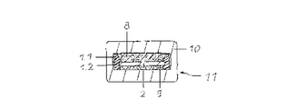
図1は、従来のPTC素子の収納装置に適用される電極端子とインシュレーターの斜視図であり、図2は、従来のPTC素子の収納装置の断面図である。 FIG. 1 is a perspective view of electrode terminals and insulators applied to a conventional PTC element storage device, and FIG. 2 is a cross-sectional view of a conventional PTC element storage device.
図1及び図2に示すように、従来のPTC素子の収納装置は、電気的に絶縁性を有する材料から形成されるインシュレーター1と、インシュレーター1の内部に嵌め込まれる電極端子2と、を備えてなる。
As shown in FIGS. 1 and 2, a conventional PTC element storage device includes an insulator 1 formed of an electrically insulating material, and an
インシュレーター1には、PTC素子8が電極端子2に当接可能に着座される凹部3が形成され、両側端に長手方向に沿って支柱1.1が形成され、前記支柱1.1の内側面には長手方向に沿って溝1.2が形成され、電極端子2の端子ラグ2.1側はインシュレーター被覆物1.3により完全に覆われる。前記支柱1.1同士は、長手方向に沿って一定間隔をあけて列設される横棒1.4により連結され、支柱1.1及び横棒1.4の内側面には多数のスタッド4が設けられる。前記スタッド4は、PTC素子8が凹部3に嵌め込まれたときにPTC素子8の側面に押し付けられてPTC素子8を固定する。前記インシュレーター1は、加熱装置に固定可能にインシュレーター被覆物1.3の反対側に側方に突き出る掛止具5が形成され、プロファイルチューブ10の内部に入り込まれる。
The insulator 1 is formed with a recess 3 in which the PTC element 8 is seated so as to be able to come into contact with the
前記PTC素子8が接触される側の反対面には絶縁ストリップ9が取り付けられ、これにより、電極端子2とプロファイルチューブ10との接触が防がれる。
An insulating strip 9 is attached to the surface opposite to the side on which the PTC element 8 is brought into contact, whereby contact between the
しかしながら、上記の如き構造を有する従来のPTC素子の収納装置は、インシュレーター1と電極端子2が摩擦力により互いに結合されるため、インシュレーター1と電極端子2との結合が解放されてしまう虞があり、インシュレーターとプロファイルチューブ10との間に埃やその他の異物が入り込んで故障が起こる可能性があるという不都合があった。
However, in the conventional PTC element storage device having the above-described structure, since the insulator 1 and the
さらに、上記の如き従来のPTC素子の収納装置は、PTC素子8が電極端子2の一側にのみ取り付け可能であるが故に、熱を満遍なく伝達できないという不都合もある。
本発明は上記事情に鑑みてなされたものであり、その目的は、接触板とインシュレーターが一体に固着され、PTC素子からの熱を満遍なく伝達可能に構成されるPTCロッド組立体を提供するところにある。 The present invention has been made in view of the above circumstances, and an object thereof is to provide a PTC rod assembly in which a contact plate and an insulator are integrally fixed so that heat from a PTC element can be transmitted evenly. is there.
さらに、本発明は、PTC素子からの生成熱が外部に抜け出ることなく放熱フィン組立体にのみ満遍なく伝達可能であり、且つ、PTCロッド組立体と放熱フィン組立体との気密性を高めるように構成される車両用のプレヒーターを提供するところにある。 Furthermore, the present invention is configured so that heat generated from the PTC element can be transmitted evenly only to the radiating fin assembly without escaping to the outside, and the airtightness between the PTC rod assembly and the radiating fin assembly is enhanced. The present invention is to provide a preheater for vehicles to be used.
上記の如き問題点を解消するために、本発明に係るPTCロッド組立体は、PTC素子を備える車両用のプレヒーターのPTCロッド組立体において、チャンネル状に形成される下側のPTCロッドと、2以上の貫通孔が一定の間隔だけ離れて形成される接触板と、前記貫通孔を貫通する貫通突起が前記接触板の一部を取り囲むように係合され、前記接触板の側面の一部を露出させる1以上の第1の着座部と第2の着座部が設けられるインシュレーターと、前記接触板と当接するように前記第1の着座部に位置するPTC素子と、前記接触板と当接するように前記第2の着座部に位置する伝熱ブロックと、前記下側のPTCロッドの開放部を覆うように係合される上側のPTCロッドと、を備えてなる。 In order to solve the above-described problems, a PTC rod assembly according to the present invention includes a lower PTC rod formed in a channel shape in a PTC rod assembly of a preheater for a vehicle including a PTC element, A contact plate in which two or more through-holes are formed apart from each other by a predetermined interval, and a through-projection penetrating the through-hole are engaged so as to surround a part of the contact plate, and a part of the side surface of the contact plate An insulator provided with one or more first seating portions and second seating portions that expose the surface, a PTC element positioned on the first seating portion so as to contact the contact plate, and contact with the contact plate Thus, the heat transfer block located in the second seating portion and the upper PTC rod engaged so as to cover the open portion of the lower PTC rod are provided.
前記接触板とインシュレーターは、2重射出工程を通じて一体に製作される。また、前記インシュレーターは、貫通孔を貫通する貫通突起が形成されて前記接触板の一方の側面に取り付けられる第1のインシュレーターと、前記貫通孔を貫通する貫通突起に係合される係合口が形成されて前記接触板の他方の側面に取り付けられる第2のインシュレーターと、を備えてなっても良い。 The contact plate and the insulator are integrally manufactured through a double injection process. The insulator has a first insulator formed on a side surface of the contact plate with a through protrusion penetrating the through hole, and an engagement port engaged with the through protrusion penetrating the through hole. And a second insulator attached to the other side surface of the contact plate.
インシュレーターはPTCロッドの外部に露出され、且つ、PTCロッドの両端を閉塞するようにガイド部が両端部にそれぞれ形成される。このとき、ガイド部は、横断面がPTCロッドの横断面と同じ形状に形成されることが好ましい。 The insulator is exposed to the outside of the PTC rod, and guide portions are formed at both ends so as to close both ends of the PTC rod. At this time, it is preferable that a guide part is formed in the same shape as the cross section of a PTC rod.
また、第1の着座部は、第2の着座部よりも広幅に形成され、支持棒は、接触板の幅方向の両端に相対するように対をなして形成されてもよい。第1の着座部と第2の着座部は、側壁に1以上の離隔突起が形成されてもよい。 Further, the first seat portion may be formed wider than the second seat portion, and the support rods may be formed in pairs so as to face both ends of the contact plate in the width direction. The first seat portion and the second seat portion may have one or more separation protrusions formed on the side walls.
接触板は、一方の端部にガイド部の外側に突き出ると共に、ステップ状に折り曲げられるターミナルが形成される。このとき、ターミナルは、接触板の端部が2つ折りになるように折り畳まれていてもよい。 The contact plate protrudes to the outside of the guide portion at one end portion, and a terminal that is bent in a step shape is formed. At this time, the terminal may be folded so that the end of the contact plate is folded in half.
ハウジングは、一側がハウジングの内部に嵌め込まれ、ハウジングの内部に嵌め込まれる上側のPTCロッドまたは下側のPTCロッドの一端と当接される折り曲げ板を備えてなるハウジング端子をさらに備える。 The housing further includes a housing terminal that is fitted on one side of the housing and includes a bent plate that comes into contact with one end of the upper PTC rod or the lower PTC rod that is fitted inside the housing.
本発明に係る車両用のプレヒーターは、上記の如き構造を有する多数のPTCロッド組立体と、PTCロッド組立体の両面に当接するように取り付けられる1以上の放熱フィン組立体と、最外郭に位置する放熱フィン組立体の外側面にそれぞれ取り付けられる一対のフレームと、PTCロッド組立体と放熱フィン組立体とフレームとの組立体の両終端部に取り付けられる第1のハウジング及び第2のハウジングと、を備えてなる。 A preheater for a vehicle according to the present invention includes a number of PTC rod assemblies having the above-described structure, one or more heat dissipating fin assemblies attached so as to be in contact with both surfaces of the PTC rod assembly, and an outermost shell. A pair of frames respectively attached to the outer surface of the radiating fin assembly positioned; a first housing and a second housing attached to both end portions of the assembly of the PTC rod assembly, the radiating fin assembly and the frame; , Provided.
最外側に位置するPTCロッド組立体は、車両用のプレヒーターの内側に向かう面にPTC素子が取り付けられるように構成され、途中に位置するPTCロッド組立体は、PTC素子と伝熱ブロックが両面に交互に取り付けられるように構成される。 The PTC rod assembly located on the outermost side is configured such that the PTC element is attached to the inner surface of the vehicle pre-heater, and the PTC rod assembly located on the middle has both sides of the PTC element and the heat transfer block. It is comprised so that it may be attached alternately.
このとき、PTCロッド組立体は、ハウジングから一定の間隔だけ離れた個所にPTC素子が取り付けられるように構成されることが好ましい。 At this time, it is preferable that the PTC rod assembly is configured such that the PTC element is attached at a position spaced apart from the housing by a predetermined distance.
また、PTCロッド組立体は、PTC素子が取り付けられた側には放熱フィン組立体が側方に2以上積層されるように取り付けられ、PTC素子が取り付けられていない側には一つの放熱フィン組立体が取り付けられる。 The PTC rod assembly is attached so that two or more radiating fin assemblies are stacked on the side where the PTC element is attached, and one radiating fin assembly is attached on the side where the PTC element is not attached. A solid is attached.
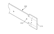
フレームは、放熱フィン組立体との接触面の長手方向に沿って長く形成される補強溝が放熱フィン組立体との接触面に設けられ、放熱フィン組立体との接触面の中段が放熱フィン組立体に向かって突き出るように斜めに形成される。 The frame is provided with a reinforcing groove formed long along the longitudinal direction of the contact surface with the radiation fin assembly on the contact surface with the radiation fin assembly, and the middle stage of the contact surface with the radiation fin assembly is the radiation fin assembly. It is formed obliquely so as to protrude toward the solid.
さらに、本発明に係るフレームは、陰極端子として働くように構成されてもよい。 Furthermore, the frame according to the present invention may be configured to function as a cathode terminal.
本発明に係るPTCロッド組立体によれば、接触板とインシュレーターとの結合力が強固になり、PTCロッドの内部に異物が流入せず、しかも、ターミナルの強度も高くなるというメリットがある。 According to the PTC rod assembly according to the present invention, there is a merit that the coupling force between the contact plate and the insulator becomes strong, foreign matter does not flow into the PTC rod, and the strength of the terminal is increased.
また、本発明に係る車両用のプレヒーターによれば、PTCロッドからの生成熱が外部に抜け出ることなく内部に満遍なく伝達され、フレームの間に位置する各部品の結合力が向上可能であり、しかも、PTCロッド組立体と放熱フィン組立体との気密性が高くなるというメリットもある。 Further, according to the preheater for a vehicle according to the present invention, the heat generated from the PTC rod is transmitted to the inside without getting out to the outside, and the coupling force of each component located between the frames can be improved. Moreover, there is a merit that the airtightness between the PTC rod assembly and the radiating fin assembly is increased.
以下、添付した図面に基づき、本発明に係るPTCロッド組立体及びこれを備える車両用のプレヒーターの実施の形態について詳述する。 Hereinafter, embodiments of a PTC rod assembly according to the present invention and a preheater for a vehicle including the same will be described in detail with reference to the accompanying drawings.
図3は、本発明に係るPTCロッド組立体の分解斜視図であり、図4ないし図6は、本発明に係るPTCロッド組立体に組み付けられる接触板のターミナルの製造過程を順次に示す斜視図である。 FIG. 3 is an exploded perspective view of the PTC rod assembly according to the present invention, and FIGS. 4 to 6 are perspective views sequentially illustrating the manufacturing process of the terminal of the contact plate assembled to the PTC rod assembly according to the present invention. It is.
図3ないし図6に示すように、本発明に係るPTCロッド組立体10は、チャンネル状に形成される下側のPTCロッド100と、一方の端部にステップ状に折り曲げられたターミナル210が設けられ、2以上の貫通孔220が一定の間隔をあけて形成されて下側のPTCロッド100の内部に位置する接触板200と、貫通孔220を貫通して接触板200の一部を取り囲むように形成され、接触板200の一方の側面の一部が露出されるように第1の着座部310が多数形成され、他方の側面の一部が露出されるように第2の着座部(図示せず)が多数形成されるインシュレーター300と、接触板200と当接するように第1の着座部310に嵌め込まれるPTC素子400と、接触板200と当接するように第2の着座部に嵌め込まれる伝熱ブロック500と、下側のPTCロッド100の開放部を覆うように取り付けられる上側のPTCロッド600と、を備えてなる。
As shown in FIGS. 3 to 6, the
インシュレーター300は、接触板200がPTCロッド100、600に当接することを防ぐためのものであり、接触板200の外側面に設けられる支持棒340を備え、接触板200の外側面の一部を取り囲むように取り付けられる。接触板200とインシュレーター300との結合構造は、図7ないし図10を参照して後述する。
さらに、インシュレーター300の両端部には、内側面がPTCロッド100、600の端部の外側面に押し付けられることにより、PTCロッド100、600の両端を閉塞するガイド部330がそれぞれ形成される。このとき、ガイド部330は、横断面がPTCロッド100、600の横断面と同じ形状に形成される。このため、上側のPTCロッド600及び下側のPTCロッド100の内部空間はガイド部330により塞がるため、PTC素子400に埃やその他の異物の接触により火災が起こることがない。
Furthermore, guide
接触板200は、一方の端部にガイド部330の外側に突き出るターミナル210が形成される。このとき、ターミナル210はステップ状に折り曲げられていてもよい。ターミナル210が形成される側の接触板200の端部は、中段よりも広幅に形成され、両端が2つ折になっている。こうして形成されるターミナル210は、厚さが接触板200の中段の2倍となるため、強度が高くなり、これにより、一層安定的に電流の伝達のためのコネクターやハウジングに組み付け可能になるというメリットがある。
The
図7は、本発明に係るPTCロッド組立体に組み付けられる接触板とインシュレーターの側面図であり、図8は、図7におけるA−A線に沿って切り取った接触板とインシュレーターの断面図であり、図9は、図7におけるB−B線に沿って切り取った接触板とインシュレーターの断面図である。 7 is a side view of the contact plate and the insulator assembled to the PTC rod assembly according to the present invention, and FIG. 8 is a cross-sectional view of the contact plate and the insulator cut along the line AA in FIG. 9 is a cross-sectional view of the contact plate and the insulator cut along the line BB in FIG.
図7ないし図9に示すように、本発明に係るインシュレーター300は、射出方式により接触板200に取り付けられ、接触板200の外側面に設けられる支持棒340を備えて接触板200の外側面の一部を取り囲むように形成される。このため、本発明に係るインシュレーター300は、貫通口220の個所の支持棒340が破損しない限り、接触板200との結合が解放されないため、接触板200の外側面との摩擦力によってのみ結合位置が固定されていた従来のインシュレーターに比べて、接触板200との結合力が著しく強固になる。このとき、インシュレーター300は、接触板200の製造とは別に行われる射出を通じて製作されてもよく、2重射出方式により接触板200と同時に製作されても良い。
As shown in FIGS. 7 to 9,
また、インシュレーター300は、PTC素子400と伝熱ブロック500の取付位置が互いに変わらないように、第1の着座部310と第2の着座部320の幅が異なるように形成されてもよい。この実施の形態においては、第1の着座部310が第2の着座部320よりも広幅に形成されているが、ユーザーの選択に応じて、第2の着座部320が第1の着座部310よりも広幅に形成されても良い。このとき、PTC素子400の一方の全面が接触板200に当接するように、第1の着座部310は接触板200と同幅に形成される。なお、第2の着座部310もまた接触板200と同幅に形成されてもよい。
Further, the
さらに、インシュレーター300は射出を通じて製作されるため、第1の着座部310が単なる四角形状に形成されると、射出工程の特性から、第1の着座部310の各隅部が直角に形成されない場合が頻繁に起こる。このように第1の着座部310の隅部が直角に形成されなかった場合、PTC素子400が接触板200に密着できなくなるため、伝熱機能が落ちてしまう。
Furthermore, since the
このため、上記の如き問題点を解消するために、本発明に係る第1の着座部310は四角形状に形成され、各隅部にはエッジ溝312が形成される。このようにしてエッジ溝312が形成されると、たとえ第1の着座部310の隅部において僅かな寸法の誤差が生じるとしても、PTC素子400は完璧に接触板200に密着可能になる。
For this reason, in order to solve the above problems, the
さらに、第2の着座部310もまた第1の着座部310と同様、各隅部部にエッジ溝が形成されて、伝熱ブロック500と接触板200との密着性を高めることができる。
Further, as with the
図10は、接触板に着脱自在に形成されるインシュレーターの分解断面図である。 FIG. 10 is an exploded cross-sectional view of an insulator that is detachably formed on the contact plate.
接触板200を取り囲むように取り付けられるインシュレーター300は、図10に示すように、貫通孔220を貫通する貫通突起308が形成されて接触板200の一方の側面に取り付けられる第1のインシュレーター306と、貫通孔220を貫通した貫通突起308に係合される係合口304が形成されて接触板200の他方の側面に取り付けられる第2のインシュレーター302と、を備えてなる。
As shown in FIG. 10, the
このような構成を有するインシュレーター300は、破損せずとも接触板200との係合が解除可能になるため、メンテナンスが容易になるというメリットがある。
Since the
図11は、支持棒が対をなして形成された本発明に係るPTC組立体のインシュレーター斜視図であり、図12は、インシュレーターと接触板にそれぞれガイド部が設けられた本発明に係るPTC組立体のインシュレーター斜視図である。 FIG. 11 is an insulator perspective view of the PTC assembly according to the present invention in which the support rods are formed in pairs, and FIG. 12 is a PTC assembly according to the present invention in which guide portions are provided on the insulator and the contact plate, respectively. It is a three-dimensional insulator perspective view.
図11に示すように、支持棒340は、接触板200の幅方向の両端に相対するように対をなして形成されても良い。
As shown in FIG. 11, the support bars 340 may be formed in pairs so as to face both ends of the
このようにして支持棒340が相対して対をなして形成されると、PTC素子400は、各隅部が支持棒340の側壁に密着されて取り付けられる。このとき、接触板200に形成される貫通口220は、各支持棒340の形成個所にそれぞれ設けられる必要がある。
When the
また、インシュレーター300に設けられるガイド部330は、図12に示すように、平板状に形成され、接触板200に向かって突き出るように貫通突起398が形成可能である。さらに、接触板200は、ガイド部330と対応する個所に補助ガイド部212が設けられる。このとき、貫通突起398と対応する個所の接触板200と補助ガイド部212には、貫通突起398が係合可能な貫通孔304が形成され、貫通突起398が貫通孔304に係止されることにより、ガイド部330と補助ガイド部212は係合される。
Moreover, the
さらに、ガイド部330と補助ガイド部212は互いに係合されたとき、PTCロッドの両端を閉塞するように形成される。
Furthermore, the
図13は、本発明に係る車両用のプレヒーターの分解斜視図であり、図14ないし図16は、本発明に係る車両用のプレヒーターに取り付けられる各PTCロッド組立体へのPTC素子と伝熱ブロックの取付位置を示す分解図である。 FIG. 13 is an exploded perspective view of the vehicle preheater according to the present invention, and FIGS. 14 to 16 show the PTC elements and the transmission to each PTC rod assembly attached to the vehicle preheater according to the present invention. It is an exploded view which shows the attachment position of a heat block.
本発明に係る車両用のプレヒーターは、図13に示すように、長手方向に平行に並ぶ多数のPTCロッド組立体10A〜10Cと、各PTCロッド組立体10A〜10Cの両面に当接するように取り付けられる放熱フィン組立体20と、放熱フィン組立体20の間に介装される陰極端子30と、最外郭に位置する放熱フィン組立体20の外側面にそれぞれ取り付けられる一対のフレーム40、50と、PTCロッド組立体10A〜10Cと放熱フィン組立体20と陰極端子30とフレーム40、50との組立体の両終端部に取り付けられる第1のハウジング60及び第2のハウジング70と、を備えてなる。放熱フィン組立体20の内部に組み込まれたPTC端子からの生成熱は、放熱フィン組立体20に伝わって放熱フィン組立体20を通過する空気を加熱する。
As shown in FIG. 13, the vehicle preheater according to the present invention is in contact with a large number of
このような構成を有する車両用のプレヒーターは、PTC素子からの生成熱が外部に抜け出ることなく、内側に配列された放熱フィン組立体20にのみ伝わるように構成されなければ、効率が高くならないため、途中に位置するPTCロッド組立体10Aは、図14に示すように、左右側に万遍無く伝熱可能にPTC素子400Aと伝熱ブロック500Aが両面に交互に取り付けられるように構成され、外側に位置するPTCロッド組立体10B、10Cは、図15及び図16に示すように、車両用のプレヒーターの内側に向かう面にPTC素子400B、400Cが取り付けられ、車両用のプレヒーターの外側に向かう面に伝熱ブロック500B、500Cが取り付けられるように構成される。
The preheater for a vehicle having such a configuration does not increase in efficiency unless it is configured so that the heat generated from the PTC element is transmitted only to the heat dissipating
しかしながら、各PTC素子400と伝熱ブロック500の取付位置はこれに限定されるものではなく、ユーザーの選択に応じて自由に変更可能である。
However, the mounting position of each
さらに、各PTC素子400A〜400Cは、ハウジング60、70を介して外部に熱が放出されないように、ハウジング60、70から一定の間隔をあけて形成されることが好ましい。
Further, each of the
また、放熱フィン組立体20へと伝わった熱は、フレーム40、50に伝わってはいけないため、フレーム40、50は、放熱フィン組立体20との接触面積が狭まるように放熱フィン組立体20との接触面に長手方向に沿って長く形成される補強溝42、52が設けられる。このようにして補強溝42、52が形成されると、放熱フィン組立体20とフレーム40、50との接触面積が狭まり、その結果、伝熱率が下がる。このとき、補強溝42、52の内部には空気が満たされるため、放熱フィン組立体20の熱が空気に乗ってフレーム40、50に伝わるとはいえ、空気は熱伝達率が極めて低い物質であるため、空気に乗って伝わる熱の量は極めて少量であると言える。
In addition, since the heat transmitted to the radiating
PTC素子からの生成熱により加熱されたPTCロッド組立体10A〜10Cと放熱フィン組立体20は嵩張って左右の外側に取り付けられたフレーム40、50を外側に押し出し、これにより、フレーム40、50は両端がハウジング60、70に係止されているため、中段部が外側に突き出るように撓むことができる。このようにフレーム40、50が撓むと、フレーム40、50の間に位置する各部品間の結合が緩むことがあるという問題点がある。
The
このため、本発明に係るフレーム40、50は、放熱フィン組立体20との接触面の中段が放熱フィン組立体20に向かって突き出るように斜めに形成される。このようにして中段部が内側に傾斜するフレーム40、50は、真っ直ぐに形成されていた従来のフレームに比べて、たとえPTCロッド組立体10A〜10Cと放熱フィン組立体20の膨張によって圧力を受けるとしても、撓みの度合いが著しく減る。さらに、本発明に係るフレーム40、50には、上述した補強溝42、52が撓むことを防ぐ心張り棒の役割を果たすため、外力による変形がほとんど起こらないという効果がある。
For this reason, the
さらに、この実施の形態においては、放熱フィン組立体20の間に別の陰極端子30が介装されているが、本発明に係る車両用のプレヒーターは、フレーム40、50が陰極端子として働くように構成されても良い。このようにフレーム40、50が陰極端子として働くと、車両用のプレヒーターの内部構成が簡単になるだけではなく、製造コストを節減できるというメリットがある。
Furthermore, in this embodiment, another
PTCロッド組立体10A〜10Cの両側面には、放熱フィン組立体20が取り付けられるが、伝熱ブロックが取り付けられた側よりも、PTC素子が取り付けられた側における生成熱量が遥かに大であるため、PTC素子が取り付けられた側には、放熱フィン組立体20が側方に多数積層されるように取り付けられ、PTC素子が取り付けられていない側にはPTC素子が取り付けられた側に固着された放熱フィン組立体20よりも少数の放熱フィン組立体20が取り付けられる。この実施の形態においては、PTC素子が取り付けられた側に2つの放熱フィン組立体20が固着され、伝熱ブロックが取り付けられた側に一つの放熱フィン組立体20が固着されているが、PTCロッド組立体10A〜10Cの側面に固着される放熱フィン組立体20の数はこれに限定されることなく、ユーザーの選択に応じて種々に変更可能である。
Although the
図17は、本発明に係る車両用のプレヒーターに取り付けられる第1のハウジングとPTCロッド組立体との結合図である。 FIG. 17 is a connection diagram of the first housing and the PTC rod assembly attached to the vehicle pre-heater according to the present invention.
本発明に係る車両用のプレヒーターの各PTCロッド組立体10A〜10Cは、PTC素子と伝熱ブロックの取付位置が異なるため、第1のハウジング60への取り付け位置が変わる場合、効率が低下したり故障したりするなどの種々の問題が生じうる。
Each of the
このような問題が起こることを抑えるために、各PTCロッド組立体10A〜10Cのターミナル210A〜210Cは、折曲の高さが異なるように形成され、第1のハウジング60は、各ターミナル210A〜210Cが取り付けられる結合端子61〜63と各ガイド部330A〜330Cを取り付けるための着座溝64〜66との距離が各ターミナル210A〜210Cの屈曲の高さに合わせて形成される。このため、各PTCロッド組立体10A〜10Cは指定された位置にのみ取り付け可能であるため、PTCロッド組立体10A〜10Cを組み立てるときに混同を生じることがない。
In order to suppress the occurrence of such a problem, the
このとき、各PTCロッド組立体10A〜10Cは、ガイド部330A〜330Cがハウジング60の内部に完全に嵌め込まれる。
At this time, the guide portions 330A to 330C of the respective
本発明に係るPTCロッド組立体付き車両用のプレヒーターは、従来のプレヒーターと比較したとき、各部の構造だけが異なり、基本的な動作は同様であるため、これについての詳細な説明を省く。 The preheater for a vehicle with a PTC rod assembly according to the present invention is different from the conventional preheater only in the structure of each part, and the basic operation is the same, so a detailed description thereof will be omitted. .
図18は、本発明に係るプレヒーターに適用されるハウジングの断面斜視図であり、図19は、ハウジング端子の結合構造を示すハウジングの断面図である。 FIG. 18 is a cross-sectional perspective view of a housing applied to the pre-heater according to the present invention, and FIG. 19 is a cross-sectional view of the housing showing a coupling structure of housing terminals.
図18及び図19に示すように、本発明に係る第1のハウジング60は、一方が第1のハウジング60の内部に嵌め込まれ、第1のハウジング60の内部に嵌め込まれる上側のPTCロッド600若しくは下側のPTCロッド100の一端と当接する折曲げ板68を備えてなるハウジング端子67を備える。このようにしてPTCロッド100、600と当接するハウジング端子67が設けられると、PTCロッド100、600の全体が陰極端子として働くため、陰極端子を別設する必要がなくなるというメリットがある。
As shown in FIGS. 18 and 19, one of the
このとき、第1のハウジング60に嵌め込まれる個所のハウジング端子67には、ハウジング端子67がハウジング60の外側に突き出ないように第1のハウジング60に押し付けられる係止突起69が形成される。このとき、係止突起69の端部は尖端状に形成され、ハウジング端子67の引き出し方向に斜めに形成することが好ましい。
At this time, a locking
以上、本発明を好適な実施の形態を挙げて詳細に説明したが、本発明の範囲は特定の実施の形態に限定されるものではなく、特許請求の範囲によって解釈されなければならない。なお、当該発明が属する技術分野における通常の知識を有する者であれば、特許請求の範囲によりクレームするような本発明の要旨を逸脱しない範囲内において各種の変更実施が可能であることを理解すべきである。 Although the present invention has been described in detail with reference to the preferred embodiments, the scope of the present invention is not limited to the specific embodiments and should be construed according to the claims. It should be noted that a person having ordinary knowledge in the technical field to which the present invention pertains understands that various modifications can be made without departing from the gist of the present invention as claimed by the claims. Should.
10:PTCロッド組立体
20:放熱フィン組立体
30:陰極端子
40、50:フレーム
60:第1のハウジング
70:第2のハウジング
100:下側のPTCロッド
200:接触板
210:ターミナル
300:インシュレーター
310:第1の着座部
320:第2の着座部
400:PTC素子
500:伝熱ブロック
600:上側のPTCロッド
10: PTC rod assembly 20: Radiation fin assembly 30:
Claims (8)
チャンネル状に形成される下側のPTCロッドと、
2以上の貫通孔が一定の間隔だけ離れて形成される接触板と、
前記接触板の一部を取り囲むように係合され、前記接触板の側面の一部を露出させる1以上の第1の着座部と第2の着座部が設けられるインシュレーターと、
前記接触板と当接するように前記第1の着座部に位置するPTC素子と、
前記接触板と当接するように前記第2の着座部に位置する伝熱ブロックと、
前記下側のPTCロッドの開放部を覆うように係合される上側のPTCロッドと、を備えてなり、
前記インシュレーターは、
貫通突起が形成されて前記接触板の一方の側面に係合される第1のインシュレーターと、
前記貫通孔を貫通する前記貫通突起に係合される係合口が形成されて前記接触板の他方の側面に取り付けられる第2のインシュレーターと、を備えてなることを特徴とするPTCロッド組立体。 In a PTC rod assembly of a preheater for a vehicle having a PTC element,
A lower PTC rod formed in a channel shape;
A contact plate in which two or more through-holes are formed at a predetermined interval;
An insulator provided with one or more first seating portions and second seating portions which are engaged so as to surround a part of the contact plate and expose a part of a side surface of the contact plate;
A PTC element positioned in the first seating portion so as to abut against the contact plate;
A heat transfer block located in the second seating portion so as to abut against the contact plate;
An upper PTC rod engaged so as to cover the open part of the lower PTC rod,
The insulator is
A first insulator that penetrations protrusions are formed engage a side of the contact plate,
The through hole P TC rod assembly and a second insulator mounted on the other side surface of the contact plate the piercing protrusion engaged are engageable opening is formed in and penetrating, you characterized in that it comprises a a Solid.
PTCロッドの両端を閉塞するガイド部が両端部にそれぞれ設けられることを特徴とする請求項1に記載のPTCロッド組立体。 The insulator is
The PTC rod assembly according to claim 1 , wherein guide portions for closing both ends of the PTC rod are provided at both ends.
チャンネル状に形成される下側のPTCロッドと、
2以上の貫通孔が一定の間隔だけ離れて形成される接触板と、
前記接触板の一部を取り囲むように係合され、前記接触板の側面の一部を露出させる1以上の第1の着座部と第2の着座部が設けられるインシュレーターと、
前記接触板と当接するように前記第1の着座部に位置するPTC素子と、
前記接触板と当接するように前記第2の着座部に位置する伝熱ブロックと、
前記下側のPTCロッドの開放部を覆うように係合される上側のPTCロッドと、を備えてなり、
前記インシュレーターは、貫通突起が形成されるガイド部が両端部に設けられ、
前記接触板は、前記ガイド部と対応する個所に補助ガイド部が設けられ、
前記貫通突起と対応する個所に貫通孔が形成され、
前記ガイド部と前記補助ガイド部は、前記PTCロッドの両端を閉塞するように形成されることを特徴とするPTCロッド組立体。 In a PTC rod assembly of a preheater for a vehicle having a PTC element,
A lower PTC rod formed in a channel shape;
A contact plate in which two or more through-holes are formed at a predetermined interval;
An insulator provided with one or more first seating portions and second seating portions which are engaged so as to surround a part of the contact plate and expose a part of a side surface of the contact plate;
A PTC element positioned in the first seating portion so as to abut against the contact plate;
A heat transfer block located in the second seating portion so as to abut against the contact plate;
An upper PTC rod engaged so as to cover the open portion of the lower PTC rod,
The insulator is provided with guide portions at both ends where a penetrating protrusion is formed,
The contact plate is provided with an auxiliary guide portion at a location corresponding to the guide portion,
A through hole is formed at a location corresponding to the through protrusion ,
The auxiliary guide portion and the guide portion, characterized by being formed so as to close both ends of the PTC rod P TC rod assembly.
前記PTCロッド組立体の両面に当接するように取り付けられる1以上の放熱フィン組立体と、
最外郭に位置する放熱フィン組立体の外側面にそれぞれ取り付けられる一対のフレームと、
前記PTCロッド組立体と前記放熱フィン組立体と前記フレームとの組立体の両終端部に取り付けられる第1のハウジング及び第2のハウジングと、
前記ハウジングの内部に組み込まれて陰極端子として働くハウジング端子と、を備えてなることを特徴とする車両用のプレヒーター。 Numerous and PTC rod assembly for the column set having a structure according to any one of claims 1 to 5,
One or more heat dissipating fin assemblies attached to abut against both sides of the PTC rod assembly;
A pair of frames each attached to the outer surface of the radiating fin assembly located on the outermost shell;
A first housing and a second housing attached to both end portions of the assembly of the PTC rod assembly, the radiation fin assembly and the frame;
A vehicle preheater comprising: a housing terminal incorporated in the housing and serving as a cathode terminal.
Applications Claiming Priority (1)
| Application Number | Priority Date | Filing Date | Title |
|---|---|---|---|
| KR1020050042386A KR100609452B1 (en) | 2005-05-20 | 2005-05-20 | Ptc rod assembly and pre-heater including the same |
Publications (2)
| Publication Number | Publication Date |
|---|---|
| JP2006327574A JP2006327574A (en) | 2006-12-07 |
| JP4322886B2 true JP4322886B2 (en) | 2009-09-02 |
Family
ID=37185050
Family Applications (1)
| Application Number | Title | Priority Date | Filing Date |
|---|---|---|---|
| JP2006139439A Expired - Fee Related JP4322886B2 (en) | 2005-05-20 | 2006-05-18 | PTC rod assembly and preheater for vehicle including the same |
Country Status (5)
| Country | Link |
|---|---|
| US (1) | US20060273078A1 (en) |
| JP (1) | JP4322886B2 (en) |
| KR (1) | KR100609452B1 (en) |
| CN (2) | CN1874618A (en) |
| DE (1) | DE102006021730B4 (en) |
Cited By (1)
| Publication number | Priority date | Publication date | Assignee | Title |
|---|---|---|---|---|
| US8319140B2 (en) | 2003-11-25 | 2012-11-27 | Fronius International Gmbh | Spot welding gun for resistance welding of workpieces |
Families Citing this family (18)
| Publication number | Priority date | Publication date | Assignee | Title |
|---|---|---|---|---|
| DE102005030392A1 (en) * | 2005-06-29 | 2007-01-04 | BSH Bosch und Siemens Hausgeräte GmbH | Domestic appliance and Garguträger holding device for a household appliance |
| KR100720131B1 (en) * | 2005-11-15 | 2007-05-18 | 모딘코리아 유한회사 | Insulator for ptc heater |
| ES2382138T3 (en) | 2007-07-18 | 2012-06-05 | Eberspächer Catem Gmbh & Co. Kg | Electric heating device |
| EP2017103B1 (en) * | 2007-07-18 | 2016-05-04 | Eberspächer catem GmbH & Co. KG | Electric heating device |
| EP2023056A1 (en) * | 2007-07-30 | 2009-02-11 | Chia-Hsiung Wu | Binding process for an air heater and structure thereof |
| WO2009096007A1 (en) * | 2008-01-30 | 2009-08-06 | Koshiro Taguchi | On-vehicle heater and its manufacturing method |
| KR20100055262A (en) * | 2008-11-17 | 2010-05-26 | 현대자동차주식회사 | High capacity ptc heater |
| US20110127247A1 (en) * | 2009-12-02 | 2011-06-02 | Hyundai Motor Company | Pre-heater apparatus for vehicle |
| EP2407327B1 (en) * | 2010-07-16 | 2013-12-25 | Eberspächer catem GmbH & Co. KG | Electric heating device, in particular additional motor vehicle heating and motor vehicle air conditioning device |
| EP2608631B1 (en) * | 2011-12-22 | 2016-09-14 | Eberspächer catem GmbH & Co. KG | Element which produces heat |
| ITRM20120022A1 (en) * | 2012-01-20 | 2013-07-21 | Bitron Spa | HEATING DEVICE. |
| US20140124499A1 (en) * | 2012-11-05 | 2014-05-08 | Betacera Inc. | Electric heating apparatus with waterproof mechanism |
| KR101792376B1 (en) * | 2013-04-28 | 2017-10-31 | 비와이디 컴퍼니 리미티드 | Electrical heater, defroster, heating and air conditioning system and vehicle |
| CN104640246A (en) * | 2015-01-19 | 2015-05-20 | 常熟市林芝电热器件有限公司 | Safe energy-saving heater structure for movable air conditioner |
| KR102512365B1 (en) | 2015-04-21 | 2023-03-23 | 한온시스템 주식회사 | PTC heater for vehicle |
| WO2016171478A1 (en) * | 2015-04-21 | 2016-10-27 | 한온시스템 주식회사 | Vehicular ptc heater |
| CN105072723A (en) * | 2015-07-28 | 2015-11-18 | 江苏源之翼电气有限公司 | Cylindrical PTC electric heater |
| CN113453389B (en) * | 2021-07-30 | 2023-11-10 | 芜湖艾尔达科技有限责任公司 | Heating device |
Family Cites Families (16)
| Publication number | Priority date | Publication date | Assignee | Title |
|---|---|---|---|---|
| NL8600142A (en) * | 1986-01-23 | 1987-08-17 | Philips Nv | METHOD FOR MANUFACTURING A SELF-REGULATING HEATING ELEMENT |
| EP0262243B1 (en) * | 1986-10-01 | 1991-02-20 | David & Baader DBK Spezialfabrik elektrischer Apparate und Heizwiderstände GmbH | Ptc-heating resistor |
| DE3869773C5 (en) * | 1988-07-15 | 2010-06-24 | Dbk David + Baader Gmbh | Radiator. |
| DE3902206A1 (en) * | 1989-01-26 | 1990-08-02 | Eichenauer Gmbh & Co Kg F | DEVICE FOR HEATING GASES |
| US5256857A (en) * | 1990-08-22 | 1993-10-26 | Texas Instruments Incorporated | Finned PTC air heater assembly for heating an automotive passenger compartment |
| JP2532502Y2 (en) * | 1991-02-20 | 1997-04-16 | 株式会社村田製作所 | Heating unit |
| US5198640A (en) * | 1991-05-28 | 1993-03-30 | Yang Chiung Hsiang | Fully clad electric ptc heater with a finned protective casing |
| JPH07153555A (en) * | 1993-11-30 | 1995-06-16 | Murata Mfg Co Ltd | Positive characteristic thermistor heater and positive characteristic thermistor heater device using it |
| JPH0855673A (en) * | 1994-08-10 | 1996-02-27 | Murata Mfg Co Ltd | Positive temperature coefficient thermister heat generating device |
| DE4434613A1 (en) * | 1994-09-28 | 1996-04-04 | Behr Gmbh & Co | Electric heating device, in particular for a motor vehicle |
| ES2204008T3 (en) * | 1998-02-20 | 2004-04-16 | Smart Gmbh | INSTALLATION OF HEATING OR AIR CONDITIONING FOR MOTOR VEHICLES. |
| DE59911409D1 (en) * | 1999-06-15 | 2005-02-10 | David & Baader Dbk Spezfab | Heating device for air heating |
| US6180930B1 (en) * | 1999-12-29 | 2001-01-30 | Chia-Hsiung Wu | Heater with enclosing envelope |
| EP1467599B1 (en) * | 2003-04-12 | 2008-11-26 | Eichenauer Heizelemente GmbH & Co.KG | Device for the admission of ceramic heating elements and procedure for the production of such |
| DE20305936U1 (en) * | 2003-04-12 | 2003-07-24 | Beru AG, 71636 Ludwigsburg | Device for accommodating ceramic heating elements in heating device has at least one contact plate on which heating elements can be placed and held by frame in force-locking manner |
| JP2007024491A (en) * | 2005-07-15 | 2007-02-01 | Modine Korea Llc | Pct rod assembly, and preheater for vehicle equipped therewith |
-
2005
- 2005-05-20 KR KR1020050042386A patent/KR100609452B1/en not_active IP Right Cessation
-
2006
- 2006-05-10 DE DE102006021730A patent/DE102006021730B4/en not_active Withdrawn - After Issue
- 2006-05-17 US US11/436,141 patent/US20060273078A1/en not_active Abandoned
- 2006-05-18 JP JP2006139439A patent/JP4322886B2/en not_active Expired - Fee Related
- 2006-05-19 CN CNA2006100824524A patent/CN1874618A/en active Pending
- 2006-05-19 CN CNA2006800176089A patent/CN101378924A/en active Pending
Cited By (1)
| Publication number | Priority date | Publication date | Assignee | Title |
|---|---|---|---|---|
| US8319140B2 (en) | 2003-11-25 | 2012-11-27 | Fronius International Gmbh | Spot welding gun for resistance welding of workpieces |
Also Published As
| Publication number | Publication date |
|---|---|
| DE102006021730A1 (en) | 2006-11-23 |
| CN1874618A (en) | 2006-12-06 |
| KR100609452B1 (en) | 2006-08-03 |
| DE102006021730B4 (en) | 2007-12-27 |
| US20060273078A1 (en) | 2006-12-07 |
| CN101378924A (en) | 2009-03-04 |
| JP2006327574A (en) | 2006-12-07 |
Similar Documents
| Publication | Publication Date | Title |
|---|---|---|
| JP4322886B2 (en) | PTC rod assembly and preheater for vehicle including the same | |
| JP2007024491A (en) | Pct rod assembly, and preheater for vehicle equipped therewith | |
| US5562844A (en) | Ptc heater radiator with frame members applying pressure to heaters | |
| US7026584B2 (en) | Electric heater with housing | |
| KR100628436B1 (en) | Ptc rod assembly and pre-heater including the same | |
| JP2528499Y2 (en) | Holding member for holding PTC element | |
| JP4315984B2 (en) | Building curtain wall | |
| KR100537748B1 (en) | Heat rod assembly and pre-heater for vehicles including the same | |
| KR100755519B1 (en) | Heat Rod Assembly and Pre-Heater for Vehicles Including the Same | |
| KR100492374B1 (en) | PTC rod assembly and Pre-heater including the same | |
| KR100879639B1 (en) | Heat Rod Assembly and Pre-Heater for Vehicles Including the Same | |
| WO2008056949A1 (en) | Ptc heater | |
| WO2006123915A1 (en) | Pre-heater for vehicle | |
| KR100811293B1 (en) | Pre-heater mounted with cover for vehicle | |
| JP6982390B2 (en) | Manufacturing method of electric heater for vehicle air conditioner | |
| KR20190033710A (en) | Assembled heat exchanger | |
| KR100720134B1 (en) | PTC rod assembly | |
| KR100926312B1 (en) | A electric heater | |
| KR100755523B1 (en) | Pre-heater for vehicles, and heat pin assembly of the same | |
| KR100720131B1 (en) | Insulator for ptc heater | |
| KR101692382B1 (en) | Curtain wall window having improved heat isolation | |
| KR200178765Y1 (en) | Pyrogenic plate of stone mattress for bedstead | |
| KR200409416Y1 (en) | A vehicle pre-heater being compact in assembly structure | |
| KR102477286B1 (en) | A heater for vehicles | |
| KR100496604B1 (en) | Heat rod assembly and pre-heater for vehicles including the same |
Legal Events
| Date | Code | Title | Description |
|---|---|---|---|
| A977 | Report on retrieval |
Free format text: JAPANESE INTERMEDIATE CODE: A971007 Effective date: 20081030 |
|
| A131 | Notification of reasons for refusal |
Free format text: JAPANESE INTERMEDIATE CODE: A131 Effective date: 20081111 |
|
| A521 | Request for written amendment filed |
Free format text: JAPANESE INTERMEDIATE CODE: A523 Effective date: 20090210 |
|
| TRDD | Decision of grant or rejection written | ||
| A01 | Written decision to grant a patent or to grant a registration (utility model) |
Free format text: JAPANESE INTERMEDIATE CODE: A01 Effective date: 20090512 |
|
| A01 | Written decision to grant a patent or to grant a registration (utility model) |
Free format text: JAPANESE INTERMEDIATE CODE: A01 |
|
| A61 | First payment of annual fees (during grant procedure) |
Free format text: JAPANESE INTERMEDIATE CODE: A61 Effective date: 20090603 |
|
| R150 | Certificate of patent or registration of utility model |
Free format text: JAPANESE INTERMEDIATE CODE: R150 |
|
| FPAY | Renewal fee payment (event date is renewal date of database) |
Free format text: PAYMENT UNTIL: 20120612 Year of fee payment: 3 |
|
| LAPS | Cancellation because of no payment of annual fees |