JP4316113B2 - Pneumatic tire - Google Patents
Pneumatic tire Download PDFInfo
- Publication number
- JP4316113B2 JP4316113B2 JP2000186764A JP2000186764A JP4316113B2 JP 4316113 B2 JP4316113 B2 JP 4316113B2 JP 2000186764 A JP2000186764 A JP 2000186764A JP 2000186764 A JP2000186764 A JP 2000186764A JP 4316113 B2 JP4316113 B2 JP 4316113B2
- Authority
- JP
- Japan
- Prior art keywords
- groove
- shoulder
- inclination angle
- groove wall
- tire
- Prior art date
- Legal status (The legal status is an assumption and is not a legal conclusion. Google has not performed a legal analysis and makes no representation as to the accuracy of the status listed.)
- Expired - Fee Related
Links
Images


Classifications
-
- B—PERFORMING OPERATIONS; TRANSPORTING
- B60—VEHICLES IN GENERAL
- B60C—VEHICLE TYRES; TYRE INFLATION; TYRE CHANGING; CONNECTING VALVES TO INFLATABLE ELASTIC BODIES IN GENERAL; DEVICES OR ARRANGEMENTS RELATED TO TYRES
- B60C11/00—Tyre tread bands; Tread patterns; Anti-skid inserts
- B60C11/03—Tread patterns
- B60C11/04—Tread patterns in which the raised area of the pattern consists only of continuous circumferential ribs, e.g. zig-zag
- B60C11/042—Tread patterns in which the raised area of the pattern consists only of continuous circumferential ribs, e.g. zig-zag further characterised by the groove cross-section
-
- B—PERFORMING OPERATIONS; TRANSPORTING
- B60—VEHICLES IN GENERAL
- B60C—VEHICLE TYRES; TYRE INFLATION; TYRE CHANGING; CONNECTING VALVES TO INFLATABLE ELASTIC BODIES IN GENERAL; DEVICES OR ARRANGEMENTS RELATED TO TYRES
- B60C11/00—Tyre tread bands; Tread patterns; Anti-skid inserts
- B60C11/03—Tread patterns
- B60C11/0306—Patterns comprising block rows or discontinuous ribs
- B60C11/0309—Patterns comprising block rows or discontinuous ribs further characterised by the groove cross-section
-
- B—PERFORMING OPERATIONS; TRANSPORTING
- B60—VEHICLES IN GENERAL
- B60C—VEHICLE TYRES; TYRE INFLATION; TYRE CHANGING; CONNECTING VALVES TO INFLATABLE ELASTIC BODIES IN GENERAL; DEVICES OR ARRANGEMENTS RELATED TO TYRES
- B60C11/00—Tyre tread bands; Tread patterns; Anti-skid inserts
- B60C11/03—Tread patterns
- B60C11/04—Tread patterns in which the raised area of the pattern consists only of continuous circumferential ribs, e.g. zig-zag
- B60C11/042—Tread patterns in which the raised area of the pattern consists only of continuous circumferential ribs, e.g. zig-zag further characterised by the groove cross-section
- B60C11/045—Tread patterns in which the raised area of the pattern consists only of continuous circumferential ribs, e.g. zig-zag further characterised by the groove cross-section the groove walls having a three-dimensional shape
-
- B—PERFORMING OPERATIONS; TRANSPORTING
- B60—VEHICLES IN GENERAL
- B60C—VEHICLE TYRES; TYRE INFLATION; TYRE CHANGING; CONNECTING VALVES TO INFLATABLE ELASTIC BODIES IN GENERAL; DEVICES OR ARRANGEMENTS RELATED TO TYRES
- B60C11/00—Tyre tread bands; Tread patterns; Anti-skid inserts
- B60C11/03—Tread patterns
- B60C11/13—Tread patterns characterised by the groove cross-section, e.g. for buttressing or preventing stone-trapping
- B60C11/1307—Tread patterns characterised by the groove cross-section, e.g. for buttressing or preventing stone-trapping with special features of the groove walls
- B60C11/1323—Tread patterns characterised by the groove cross-section, e.g. for buttressing or preventing stone-trapping with special features of the groove walls asymmetric
-
- Y—GENERAL TAGGING OF NEW TECHNOLOGICAL DEVELOPMENTS; GENERAL TAGGING OF CROSS-SECTIONAL TECHNOLOGIES SPANNING OVER SEVERAL SECTIONS OF THE IPC; TECHNICAL SUBJECTS COVERED BY FORMER USPC CROSS-REFERENCE ART COLLECTIONS [XRACs] AND DIGESTS
- Y10—TECHNICAL SUBJECTS COVERED BY FORMER USPC
- Y10S—TECHNICAL SUBJECTS COVERED BY FORMER USPC CROSS-REFERENCE ART COLLECTIONS [XRACs] AND DIGESTS
- Y10S152/00—Resilient tires and wheels
- Y10S152/90—Tread pattern having no blocks and having circumferential ribs defined by zig-zag circumferential grooves
Description
【0001】
【発明の属する技術分野】
本発明は、トレッド面にタイヤ周方向に延びる複数本の主溝を設けた空気入りタイヤに関し、さらに詳しくは、主溝周りに発生する偏摩耗の抑制を可能にした空気入りタイヤに関する。
【0002】
【従来の技術】
一般に、空気入りタイヤのトレッド面には、金型内面形状に基づいて、タイヤ子午線方向の単一又は複数の曲率半径(トレッドラジアス)からなる曲率が付与されている。一方、空気入りタイヤは、トレッド部に埋設したベルト層やトレッドゴム等の内部構造に起因して、内圧充填時にトレッド面の曲率半径が変化しようとする。このようにインフレートによってトレッド面の曲率半径に変化を生じると、その変化は溝部分で吸収されるので、トレッド部が溝底を境にして折れ曲がるような現象を生じる。特に、タイヤ周方向に延びる複数本の主溝を備えたリブタイヤでは、上記折れ曲がり現象が顕著に現れる。
【0003】
上述のようにトレッド部が溝底を境にして折れ曲がると、その溝に隣接するリブの縁部がトレッド面の所定の曲率半径に対して不一致となり、リブ縁部での接地圧が著しく変化する。その結果、リブ縁部を起点として偏摩耗を生じ、それがレール摩耗に成長してしまうのである。
【0004】
【発明が解決しようとする課題】
本発明の目的は、インフレート時にトレッドラジアスの変化に起因して主溝の溝幅が広がる場合であっても、その主溝周りに発生する偏摩耗を効果的に抑制することを可能にした空気入りタイヤを提供することにある。
【0005】
【課題を解決するための手段】
上記目的を達成するための本発明の空気入りタイヤは、トレッド面にタイヤ周方向に延びる複数本の主溝を設けた空気入りタイヤにおいて、前記複数本の主溝のうち、タイヤ幅方向に振幅するジグザグ形状を有し、かつインフレート時に溝幅が広がる主溝について、ショルダー寄りの屈曲部ではセンター寄りの溝壁のトレッド面に対する傾斜角度を90°より大きくする一方でショルダー寄りの溝壁の傾斜角度を90°より小さくすると共に、センター寄りの屈曲部ではショルダー寄りの溝壁のトレッド面に対する傾斜角度を90°より大きくする一方でセンター寄りの溝壁の傾斜角度を90°より小さくし、これら対向する溝壁の傾斜角度が互いに異なる部位をタイヤ周方向に不連続に配置したことを特徴とするものである。
【0006】
本発明者等は、レール摩耗等の偏摩耗の発生メカニズムについて鋭意研究した結果、ジグザグ形状を有する主溝の溝幅がインフレート時にトレッドラジアスの変化に起因して広がる場合、主溝屈曲部で凸形状となるエッジ部の接地圧が局部的に高くなり、その部分を起点として偏摩耗が生じるということを知見した。
【0007】
そこで、上述のようにインフレート時にトレッドラジアスの変化に起因して溝幅が広がるジグザグ形状の主溝について、ショルダー寄りの屈曲部ではセンター寄りの溝壁の傾斜角度を相対的に大きくすると共に、センター寄りの屈曲部ではショルダー寄りの溝壁の傾斜角度を相対的に大きくすることにより、これら部位の剛性を小さくし、リブ縁部における接地圧の増加を抑制するので、主溝周りに発生するレール摩耗等の偏摩耗を効果的に抑制することができる。
【0008】
より具体的には、インフレート時に溝幅が広がる主溝について、ショルダー寄りの屈曲部ではセンター寄りの溝壁のトレッド面に対する傾斜角度を90°より大きくする一方でショルダー寄りの溝壁の傾斜角度を90°より小さくすると共に、センター寄りの屈曲部ではショルダー寄りの溝壁のトレッド面に対する傾斜角度を90°より大きくする一方でセンター寄りの溝壁の傾斜角度を90°より小さくする。このように傾斜角度が90°より小さい溝壁と傾斜角度が90°より大きいオーバーハング形状の溝壁とを対向させることにより、主溝両側の剛性を効果的に調整することができる。
【0009】
また、対向する溝壁の傾斜角度が互いに異なる部位(剛性調整部)をタイヤ周方向に不連続に配置するにあたって、インフレート時に溝幅が広がる主溝のタイヤ周方向のジグザグピッチZに対して、上記剛性調整部を溝屈曲点から前後各0.15Z以内の領域に設けることが好ましい。
【0010】
【発明の実施の形態】
以下、本発明の構成について添付の図面を参照して詳細に説明する。
【0011】
図1は本発明の実施形態からなる空気入りタイヤを示し、1はトレッド部、2はサイドウォール部、3はビード部である。左右一対のビード部3,3間にはカーカス層4が装架され、そのタイヤ幅方向両端部がそれぞれビードコア5の廻りにタイヤ内側から外側へ巻き上げられている。トレッド部1におけるカーカス層4の外周側には、複数のベルト層6が埋設されている。
【0012】
図2に示すように、トレッド面1aにはタイヤ周方向に延びるストレート形状を有する複数本の主溝7aと、タイヤ幅方向に振幅しながらタイヤ周方向に延びるジグザグ形状を有する複数本の主溝7bが形成されている。主溝7aはトレッドセンター側に位置し、主溝7bは主溝7aよりもショルダー側に位置している。これら主溝7a,7bによって複数列のリブ8が区分されている。なお、トレッド面1aには必要に応じてタイヤ幅方向に延びる横溝やサイプ等を設けるようにしても良い。
【0013】
上記空気入りタイヤは、トレッド部1に埋設したベルト層6やトレッドゴム等の内部構造に起因して、インフレート時にトレッド面1aの曲率半径が変化し、トレッド部1が主としてショルダー側の主溝7bの溝底を境にして折れ曲がり、その結果、主溝7bの溝幅がインフレート前に比べて僅かに広がるようになっている。このような折れ曲がり現象を生じるタイヤ内部構造は、ベルト層6やトレッドゴム等に基づいて意図的に設計することが可能である。例えば、トレッドショルダー付近の周剛性を相対的に高くすれば、インフレート時においてセンター付近の外周成長が相対的に大きくなる。
【0014】
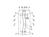
インフレート時に溝幅が広がる主溝7bは、図3に示すように、ショルダー寄りの屈曲部ではセンター寄りの溝壁W1 の傾斜角度がショルダー寄りの溝壁W2 の傾斜角度よりも大きくなっていると共に、センター寄りの屈曲部ではショルダー寄りの溝壁W2 の傾斜角度がセンター寄りの溝壁W1 の傾斜角度よりも大きくなっている。図3において、主溝7bの実線部はトレッド表面での輪郭線を示し、破線部は溝底での輪郭線を示すものである。
【0015】
図4〜図6はそれぞれ図3のA−A矢視断面図、B−B矢視断面図、C−C矢視断面図である。図4に示すように、主溝7bのショルダー寄りの屈曲部では、センター寄りの溝壁W1 のトレッド面1aに対する傾斜角度α1 がショルダー寄りの溝壁W2 のトレッド面1aに対する傾斜角度β1 よりも大きくなっている。即ち、ショルダー寄りの屈曲部ではセンター寄りの溝壁W1 の傾斜角度α1 が90°より大きく、ショルダー寄りの溝壁W2 の傾斜角度β1 が90°より小さく設定されている。
【0016】
図5に示すように、主溝7bの屈曲部間の任意の位置では、センター寄りの溝壁W1 のトレッド面1aに対する傾斜角度α2 とショルダー寄りの溝壁W2 のトレッド面1aに対する傾斜角度β2 とが互いに等しくなっている。これら屈曲部間の任意の位置ではセンター寄りの溝壁W1 の傾斜角度α2 とショルダー寄りの溝壁W2 の傾斜角度β2 が共に90°より小さく設定されている。但し、傾斜角度α2 ,β2 は90°より小さい範囲で若干互いに異なっていても良い。
【0017】
図6に示すように、主溝7bのセンター寄りの屈曲部では、ショルダー寄りの溝壁W2 のトレッド面1aに対する傾斜角度β3 がセンター寄りの溝壁W1 のトレッド面1aに対する傾斜角度α3 よりも大きくなっている。即ち、センター寄りの屈曲部ではショルダー寄りの溝壁W2 の傾斜角度β3 が90°より大きく、センター寄りの溝壁W1 の傾斜角度α3 が90°より小さく設定されている。
【0018】
上記空気入りタイヤは、図1の一点鎖線にて示すように、インフレート時にトレッド部1が主としてショルダー側の主溝7bの溝底を境にして折れ曲がり、主溝7bの溝幅がインフレート前に比べて僅かに広がるようになる。そのため、図2に示すように、主溝屈曲部で凸形状となるエッジ部Eの接地圧が局部的に高くなる傾向にある。しかしながら、上述のように主溝7bのショルダー寄りの屈曲部ではセンター寄りの溝壁W1 の傾斜角度α1 を相対的に大きくすると共に、センター寄りの屈曲部ではショルダー寄りの溝壁W2 の傾斜角度β3 を相対的に大きくすることにより、これらエッジ部Eの近傍の剛性を小さくし、リブ縁部における接地圧の増加を抑制しているので、主溝周りに発生するレール摩耗等の偏摩耗を効果的に抑制することができる。
【0019】
上記空気入りタイヤにおいて、インフレート時に溝幅が広がる主溝7bの対向する溝壁W1 ,W2 の傾斜角度を互いに異ならせた剛性調整部9は、図3の如くタイヤ周方向に不連続に配置されている。即ち、剛性を低下させるべき部分を局部的に配置し、それ以外の部分の初期剛性は変化させないようにするので、偏摩耗を効果的に抑制することが可能になる。剛性調整部9をタイヤ周方向に不連続に配置するにあたって、インフレート時に溝幅が広がる主溝7bのタイヤ周方向のジグザグピッチZに対して、剛性調整部9を溝屈曲点から前後各0.15Z以内の領域に設けるようにする。この剛性調整部9が溝屈曲点から前後各0.15Z以内の領域から外れると、接地圧の均一性が低下して偏摩耗を生じ易くなる。なお、ジグザグ形状を有する主溝7bが明確な屈曲点を備えていない場合には、屈曲部に向けて主溝の輪郭線を延長し、その延長線の交点を屈曲点と仮定すれば良い。
【0020】
本発明において、トレッド面に設ける主溝の本数は特に限定されるものではなく、少なくとも一部のジグザグ形状を有する主溝の溝幅がインフレート時に広がるものであれば良い。
【0021】
【実施例】
タイヤサイズ11.00R22.5とし、トレッドパターンだけを異ならせた本発明タイヤ及び従来タイヤをそれぞれ製作した。
【0022】
本発明タイヤ:
図1に示すように、トレッド面にタイヤ周方向に延びる複数本の主溝を設けた空気入りタイヤにおいて、タイヤ幅方向に振幅するジグザグ形状を有し、かつインフレート時に溝幅が広がる主溝について、ショルダー寄りの屈曲部ではセンター寄りの溝壁の傾斜角度α1 を100°に設定する一方でショルダー寄りの溝壁の傾斜角度β1 を80°に設定すると共に、センター寄りの屈曲部ではショルダー寄りの溝壁の傾斜角度β3 を100°に設定する一方でセンター寄りの溝壁の傾斜角度α3 を80°に設定し、これら対向する溝壁の傾斜角度が互いに異なる部位をタイヤ周方向に不連続に配置した。
【0023】
従来タイヤ:
図1において、インフレート時に溝幅が広がるジグザグ形状の主溝の両溝壁のトレッド面に対する傾斜角度をそれぞれ80°に設定した。
【0024】
これら試験タイヤについて偏摩耗性を評価した。偏摩耗性の評価として、本発明タイヤ及び従来タイヤをそれぞれ8台のトラックのフロントに2本づつ装着し、高速道主体で6万km走行した後、各タイヤのトレッド面における偏摩耗の発生状況を観察した。
【0025】
その結果、従来タイヤは16本中6本にレール摩耗が発生していた。一方、本発明タイヤは16本中2本だけに兆候の見られるものも含めてレール摩耗が発生していた。
【0026】
【発明の効果】
以上説明したように本発明によれば、トレッド面にタイヤ周方向に延びる複数本の主溝を設けた空気入りタイヤにおいて、複数本の主溝のうち、タイヤ幅方向に振幅するジグザグ形状を有し、かつインフレート時に溝幅が広がる主溝について、ショルダー寄りの屈曲部ではセンター寄りの溝壁のトレッド面に対する傾斜角度を90°より大きくする一方でショルダー寄りの溝壁の傾斜角度を90°より小さくすると共に、センター寄りの屈曲部ではショルダー寄りの溝壁のトレッド面に対する傾斜角度を90°より大きくする一方でセンター寄りの溝壁の傾斜角度を90°より小さくし、これら対向する溝壁の傾斜角度が互いに異なる部位をタイヤ周方向に不連続に配置したから、主溝周りに発生する偏摩耗を効果的に抑制することができる。
【図面の簡単な説明】
【図1】本発明の実施形態からなる空気入りタイヤを示す子午線断面図である。
【図2】本発明の実施形態からなる空気入りタイヤのトレッドパターンを示す展開図である。
【図3】本発明の実施形態からなる空気入りタイヤの要部を示す拡大平面図である。
【図4】図3のA−A矢視断面図である。
【図5】図3のB−B矢視断面図である。
【図6】図3のC−C矢視断面図である。
【符号の説明】
1 トレッド部
1a トレッド面
2 サイドウォール部
3 ビード部
4 カーカス層
5 ビードコア
6 ベルト層
7a,7b 主溝
8 リブ
9 剛性調整部
W1 センター寄りの溝壁
W2 ショルダー寄りの溝壁
α1 ,α2 ,α3 センター寄りの溝壁の傾斜角度
β1 ,β2 ,β3 ショルダー寄りの溝壁の傾斜角度[0001]
BACKGROUND OF THE INVENTION
The present invention relates to a pneumatic tire provided with a plurality of main grooves extending in the tire circumferential direction on a tread surface, and more particularly to a pneumatic tire capable of suppressing uneven wear generated around the main groove.
[0002]
[Prior art]
In general, a tread surface of a pneumatic tire is provided with a curvature composed of a single or a plurality of curvature radii (tread radius) in the tire meridian direction based on the inner surface shape of the mold. On the other hand, in a pneumatic tire, the radius of curvature of the tread surface tends to change during internal pressure filling due to an internal structure such as a belt layer or a tread rubber embedded in the tread portion. When the curvature radius of the tread surface is changed by inflation as described above, the change is absorbed by the groove portion, and thus a phenomenon occurs in which the tread portion is bent at the groove bottom. In particular, in the case of a rib tire having a plurality of main grooves extending in the tire circumferential direction, the bending phenomenon appears remarkably.
[0003]
As described above, when the tread portion bends at the groove bottom, the edge of the rib adjacent to the groove becomes inconsistent with the predetermined radius of curvature of the tread surface, and the contact pressure at the rib edge changes significantly. . As a result, uneven wear occurs starting from the rib edge, which grows into rail wear.
[0004]
[Problems to be solved by the invention]
The object of the present invention is to effectively suppress uneven wear that occurs around the main groove even when the groove width of the main groove widens due to changes in tread radius during inflation. It is to provide a pneumatic tire.
[0005]
[Means for Solving the Problems]
In order to achieve the above object, a pneumatic tire according to the present invention is a pneumatic tire in which a plurality of main grooves extending in the tire circumferential direction are provided on a tread surface, and the amplitude of the plurality of main grooves in the tire width direction is increased. For the main groove having a zigzag shape that expands when inflated, the inclination angle of the groove wall near the shoulder with respect to the tread surface of the groove near the shoulder is larger than 90 °, while the groove wall near the shoulder While making the inclination angle smaller than 90 °, the inclination angle of the groove wall near the shoulder with respect to the tread surface of the groove wall near the shoulder is made larger than 90 °, while the inclination angle of the groove wall near the center is made smaller than 90 °, The portions where the inclination angles of the facing groove walls are different from each other are discontinuously arranged in the tire circumferential direction.
[0006]
As a result of earnest research on the occurrence mechanism of uneven wear such as rail wear, the present inventors have found that when the groove width of the main groove having a zigzag shape widens due to a change in tread radius during inflation, It has been found that the contact pressure at the edge portion having a convex shape increases locally, and uneven wear occurs starting from that portion.
[0007]
Therefore, as described above, with respect to the zigzag main groove in which the groove width widens due to the change in the tread radius during inflation, the angle of inclination of the groove wall near the center is relatively increased in the bent portion near the shoulder, and In the bent part near the center, by increasing the inclination angle of the groove wall near the shoulder, the rigidity of these parts is reduced and the increase in the contact pressure at the rib edge part is suppressed. Uneven wear such as rail wear can be effectively suppressed.
[0008]
More specifically, with respect to the main groove where the groove width is widened during inflation, the inclination angle of the groove wall near the shoulder is larger than 90 ° with respect to the tread surface of the groove wall near the center at the bent part near the shoulder. The angle of inclination of the groove wall near the shoulder with respect to the tread surface is made larger than 90 ° while the angle of inclination of the groove wall near the center is made smaller than 90 ° . Thus, by making the groove wall having an inclination angle smaller than 90 ° and the overhanging groove wall having an inclination angle larger than 90 ° face each other, the rigidity on both sides of the main groove can be effectively adjusted.
[0009]
In addition, when disposing discontinuous portions in the tire circumferential direction (stiffness adjusting portions) where the inclination angles of the opposing groove walls are different from each other, the zigzag pitch Z in the tire circumferential direction of the main groove in which the groove width widens during inflation It is preferable that the rigidity adjusting portion is provided in a region within 0.15Z before and after the groove bending point.
[0010]
DETAILED DESCRIPTION OF THE INVENTION
Hereinafter, the configuration of the present invention will be described in detail with reference to the accompanying drawings.
[0011]
FIG. 1 shows a pneumatic tire according to an embodiment of the present invention, wherein 1 is a tread portion, 2 is a sidewall portion, and 3 is a bead portion. A
[0012]
As shown in FIG. 2, the
[0013]
In the pneumatic tire, the radius of curvature of the
[0014]
[0015]
4 to 6 are respectively a cross-sectional view taken along line AA, a cross-sectional view taken along line BB, and a cross-sectional view taken along line CC in FIG. As shown in FIG. 4, the shoulder side of the bent portion of the
[0016]
As shown in FIG. 5, in any position between the bent portion of the
[0017]
As shown in FIG. 6, the bent portion near the center of the
[0018]
In the pneumatic tire, as shown by a one-dot chain line in FIG. 1, the
[0019]
In the pneumatic tire described above, the
[0020]
In the present invention, the number of main grooves provided on the tread surface is not particularly limited as long as the groove width of at least a part of the main grooves having a zigzag shape widens during inflation.
[0021]
【Example】
A tire of the present invention and a conventional tire having a tire size of 11.00R22.5 and different tread patterns were produced.
[0022]
Invention tire:
As shown in FIG. 1, in a pneumatic tire having a plurality of main grooves extending in the tire circumferential direction on the tread surface, the main groove has a zigzag shape that swings in the tire width direction and the groove width is widened during inflation. In the bent portion near the shoulder, the inclination angle α 1 of the groove wall near the center is set to 100 °, while the inclination angle β 1 of the groove wall near the shoulder is set to 80 °, The inclination angle β 3 of the groove wall near the shoulder is set to 100 °, while the inclination angle α 3 of the groove wall near the center is set to 80 °, and the portions where the inclination angles of the opposed groove walls are different from each other are Discontinuously arranged in the direction.
[0023]
Conventional tire:
In FIG. 1, the inclination angles of the two groove walls of the zigzag main groove where the groove width is widened during inflation with respect to the tread surface are set to 80 °.
[0024]
These test tires were evaluated for uneven wear. As an evaluation of uneven wear, two tires according to the present invention and two conventional tires are mounted on the front of each of the eight trucks, and after running 60,000 km mainly on the highway, the occurrence of uneven wear on the tread surface of each tire Was observed.
[0025]
As a result, rail wear occurred in 6 of 16 conventional tires. On the other hand, in the tire of the present invention, rail wear occurred, including those in which only 2 out of 16 signs were observed.
[0026]
【The invention's effect】
As described above, according to the present invention, a pneumatic tire having a plurality of main grooves extending in the tire circumferential direction on the tread surface has a zigzag shape that swings in the tire width direction among the plurality of main grooves. In addition, for the main groove where the groove width is widened at the time of inflation, the inclination angle of the groove wall near the center with respect to the tread surface is larger than 90 ° while the inclination angle of the groove wall near the shoulder is 90 °. The angle of the groove wall near the shoulder with respect to the tread surface of the groove near the center is made larger than 90 ° while the angle of inclination of the groove wall near the center is made smaller than 90 °. Since the portions having different inclination angles are discontinuously arranged in the tire circumferential direction, uneven wear that occurs around the main groove can be effectively suppressed.
[Brief description of the drawings]
FIG. 1 is a meridian cross-sectional view showing a pneumatic tire according to an embodiment of the present invention.
FIG. 2 is a development view showing a tread pattern of a pneumatic tire according to an embodiment of the present invention.
FIG. 3 is an enlarged plan view showing a main part of the pneumatic tire according to the embodiment of the present invention.
4 is a cross-sectional view taken along the line AA in FIG. 3;
5 is a cross-sectional view taken along the line B-B in FIG. 3;
6 is a cross-sectional view taken along the line CC in FIG. 3;
[Explanation of symbols]
DESCRIPTION OF
Claims (2)
Priority Applications (2)
| Application Number | Priority Date | Filing Date | Title |
|---|---|---|---|
| JP2000186764A JP4316113B2 (en) | 2000-06-21 | 2000-06-21 | Pneumatic tire |
| US09/881,700 US6595254B2 (en) | 2000-06-21 | 2001-06-18 | Pneumatic tire including zig-zag main grooves |
Applications Claiming Priority (1)
| Application Number | Priority Date | Filing Date | Title |
|---|---|---|---|
| JP2000186764A JP4316113B2 (en) | 2000-06-21 | 2000-06-21 | Pneumatic tire |
Publications (3)
| Publication Number | Publication Date |
|---|---|
| JP2002002226A JP2002002226A (en) | 2002-01-08 |
| JP2002002226A5 JP2002002226A5 (en) | 2006-08-03 |
| JP4316113B2 true JP4316113B2 (en) | 2009-08-19 |
Family
ID=18686871
Family Applications (1)
| Application Number | Title | Priority Date | Filing Date |
|---|---|---|---|
| JP2000186764A Expired - Fee Related JP4316113B2 (en) | 2000-06-21 | 2000-06-21 | Pneumatic tire |
Country Status (2)
| Country | Link |
|---|---|
| US (1) | US6595254B2 (en) |
| JP (1) | JP4316113B2 (en) |
Cited By (1)
| Publication number | Priority date | Publication date | Assignee | Title |
|---|---|---|---|---|
| KR20180079758A (en) * | 2017-01-02 | 2018-07-11 | 넥센타이어 주식회사 | Pneumatic tire |
Families Citing this family (4)
| Publication number | Priority date | Publication date | Assignee | Title |
|---|---|---|---|---|
| US7278294B2 (en) * | 2005-04-12 | 2007-10-09 | Durham Kenimer Giles | System and method for determining atomization characteristics of spray liquids |
| US9278582B2 (en) | 2010-12-21 | 2016-03-08 | Bridgestone Americas Tire Operations, Llc | Tire tread having developing grooves |
| TWI488758B (en) * | 2012-09-17 | 2015-06-21 | Cheng Shin Rubber Ind Co Ltd | Tire tread structure with multiple asymmetric surface trenches |
| US11214100B2 (en) * | 2017-08-03 | 2022-01-04 | Sumitomo Rubber Industries, Ltd. | Tire |
Family Cites Families (19)
| Publication number | Priority date | Publication date | Assignee | Title |
|---|---|---|---|---|
| US3055410A (en) * | 1960-01-29 | 1962-09-25 | Atlas Supply Company | Tires |
| DE1480927A1 (en) * | 1964-01-15 | 1969-03-13 | Continental Gummi Werke Ag | Tread design for vehicle tires, especially pneumatic tires |
| FR2050653A5 (en) * | 1969-06-19 | 1971-04-02 | Michelin & Cie | |
| JPS5250717B2 (en) * | 1973-07-02 | 1977-12-27 | ||
| JPS5244903A (en) * | 1975-10-07 | 1977-04-08 | Bridgestone Corp | Pneumatic tire for heavy vehicle to reduce railway wear |
| JPS52140102A (en) * | 1976-05-19 | 1977-11-22 | Bridgestone Corp | Pneumatic tyre with less partial wear |
| JPS60197409A (en) * | 1984-03-21 | 1985-10-05 | Toyo Tire & Rubber Co Ltd | Pneumatic tire for automobile |
| JPS63166606A (en) * | 1986-12-27 | 1988-07-09 | Ohtsu Tire & Rubber Co Ltd | Bias tire for truck and bus |
| JPH02155808A (en) * | 1988-12-09 | 1990-06-14 | Yokohama Rubber Co Ltd:The | Pneumatic tire |
| JP2879699B2 (en) * | 1990-06-28 | 1999-04-05 | 横浜ゴム株式会社 | Flat pneumatic tire for heavy loads |
| JP3115585B2 (en) * | 1990-10-02 | 2000-12-11 | 株式会社ブリヂストン | Pneumatic radial tire |
| JPH04372405A (en) * | 1991-06-19 | 1992-12-25 | Toyo Tire & Rubber Co Ltd | Uneven abrasion-prevented pneumatic radial tire |
| JP3076089B2 (en) * | 1991-06-25 | 2000-08-14 | 株式会社ブリヂストン | Heavy duty pneumatic tires |
| JP3363177B2 (en) * | 1992-07-29 | 2003-01-08 | 東洋ゴム工業株式会社 | Pneumatic tire |
| JP3366093B2 (en) * | 1993-12-24 | 2003-01-14 | 横浜ゴム株式会社 | Pneumatic radial tire |
| JP3398730B2 (en) * | 1994-06-22 | 2003-04-21 | 東洋ゴム工業株式会社 | Pneumatic radial tire for heavy loads |
| JPH10272906A (en) * | 1997-03-28 | 1998-10-13 | Yokohama Rubber Co Ltd:The | Pneumatic tire and mold for forming such tire |
| JP4149058B2 (en) * | 1998-12-18 | 2008-09-10 | 株式会社ブリヂストン | Heavy duty pneumatic tire |
| US6412531B1 (en) * | 1999-07-15 | 2002-07-02 | Michelin Recherche Et Technique S.A. | Tire tread having groove walls with compound contours |
-
2000
- 2000-06-21 JP JP2000186764A patent/JP4316113B2/en not_active Expired - Fee Related
-
2001
- 2001-06-18 US US09/881,700 patent/US6595254B2/en not_active Expired - Fee Related
Cited By (2)
| Publication number | Priority date | Publication date | Assignee | Title |
|---|---|---|---|---|
| KR20180079758A (en) * | 2017-01-02 | 2018-07-11 | 넥센타이어 주식회사 | Pneumatic tire |
| KR101890367B1 (en) * | 2017-01-02 | 2018-08-21 | 넥센타이어 주식회사 | Pneumatic tire |
Also Published As
| Publication number | Publication date |
|---|---|
| US20020000277A1 (en) | 2002-01-03 |
| US6595254B2 (en) | 2003-07-22 |
| JP2002002226A (en) | 2002-01-08 |
Similar Documents
| Publication | Publication Date | Title |
|---|---|---|
| US8770241B2 (en) | Pneumatic tire with tread having wave shaped circumferential groove | |
| JP2968090B2 (en) | All season tire tread | |
| JP4202169B2 (en) | Pneumatic radial tire | |
| EP0688685B1 (en) | Pneumatic Tires | |
| JP4202168B2 (en) | Pneumatic radial tire | |
| JP2002059711A (en) | Pneumatic tire | |
| JP2013071633A (en) | Pneumatic tire | |
| EP0733497B1 (en) | Pneumatic tyre | |
| JP7078389B2 (en) | Pneumatic tires | |
| JP6911663B2 (en) | tire | |
| JP2017065625A (en) | Pneumatic tire | |
| JP4316112B2 (en) | Pneumatic tire | |
| JP4316113B2 (en) | Pneumatic tire | |
| US6796349B2 (en) | Pneumatic tire including protrusion dividing groove space of main groove having groove width narrowed during inflation | |
| JPH0848115A (en) | Pneumatic radial tire | |
| JP2001163013A (en) | Pneumatic tire | |
| JPS61196807A (en) | Pneumatic tire | |
| JP2021160698A (en) | Pneumatic tire | |
| JPH06191226A (en) | Pneumatic tire | |
| JP6248374B2 (en) | Pneumatic tire | |
| JP2002002227A (en) | Pneumatic tire | |
| EP3446891B1 (en) | Tire and tire mold | |
| JP3642652B2 (en) | Pneumatic radial tire | |
| EP1167084B1 (en) | Pneumatic tires | |
| JP2021088310A (en) | Pneumatic tire |
Legal Events
| Date | Code | Title | Description |
|---|---|---|---|
| A521 | Written amendment |
Free format text: JAPANESE INTERMEDIATE CODE: A523 Effective date: 20060621 |
|
| A621 | Written request for application examination |
Free format text: JAPANESE INTERMEDIATE CODE: A621 Effective date: 20060621 |
|
| A977 | Report on retrieval |
Free format text: JAPANESE INTERMEDIATE CODE: A971007 Effective date: 20090130 |
|
| A131 | Notification of reasons for refusal |
Free format text: JAPANESE INTERMEDIATE CODE: A131 Effective date: 20090210 |
|
| A521 | Written amendment |
Free format text: JAPANESE INTERMEDIATE CODE: A523 Effective date: 20090326 |
|
| TRDD | Decision of grant or rejection written | ||
| A01 | Written decision to grant a patent or to grant a registration (utility model) |
Free format text: JAPANESE INTERMEDIATE CODE: A01 Effective date: 20090512 |
|
| A01 | Written decision to grant a patent or to grant a registration (utility model) |
Free format text: JAPANESE INTERMEDIATE CODE: A01 |
|
| A61 | First payment of annual fees (during grant procedure) |
Free format text: JAPANESE INTERMEDIATE CODE: A61 Effective date: 20090520 |
|
| R150 | Certificate of patent or registration of utility model |
Free format text: JAPANESE INTERMEDIATE CODE: R150 |
|
| FPAY | Renewal fee payment (event date is renewal date of database) |
Free format text: PAYMENT UNTIL: 20120529 Year of fee payment: 3 |
|
| FPAY | Renewal fee payment (event date is renewal date of database) |
Free format text: PAYMENT UNTIL: 20120529 Year of fee payment: 3 |
|
| FPAY | Renewal fee payment (event date is renewal date of database) |
Free format text: PAYMENT UNTIL: 20120529 Year of fee payment: 3 |
|
| FPAY | Renewal fee payment (event date is renewal date of database) |
Free format text: PAYMENT UNTIL: 20130529 Year of fee payment: 4 |
|
| FPAY | Renewal fee payment (event date is renewal date of database) |
Free format text: PAYMENT UNTIL: 20130529 Year of fee payment: 4 |
|
| FPAY | Renewal fee payment (event date is renewal date of database) |
Free format text: PAYMENT UNTIL: 20130529 Year of fee payment: 4 |
|
| FPAY | Renewal fee payment (event date is renewal date of database) |
Free format text: PAYMENT UNTIL: 20140529 Year of fee payment: 5 |
|
| R250 | Receipt of annual fees |
Free format text: JAPANESE INTERMEDIATE CODE: R250 |
|
| R250 | Receipt of annual fees |
Free format text: JAPANESE INTERMEDIATE CODE: R250 |
|
| LAPS | Cancellation because of no payment of annual fees |