JP4315331B2 - Electrical connector - Google Patents
Electrical connector Download PDFInfo
- Publication number
- JP4315331B2 JP4315331B2 JP2003358063A JP2003358063A JP4315331B2 JP 4315331 B2 JP4315331 B2 JP 4315331B2 JP 2003358063 A JP2003358063 A JP 2003358063A JP 2003358063 A JP2003358063 A JP 2003358063A JP 4315331 B2 JP4315331 B2 JP 4315331B2
- Authority
- JP
- Japan
- Prior art keywords
- contact
- contact piece
- piece
- electrical connector
- actuator
- Prior art date
- Legal status (The legal status is an assumption and is not a legal conclusion. Google has not performed a legal analysis and makes no representation as to the accuracy of the status listed.)
- Expired - Fee Related
Links
Images


Description
この発明は、フレキシブル印刷配線基板を電気的に接続する電気コネクタに関し、特にその装着を簡単にした電気コネクタに関する。 The present invention relates to an electrical connector for electrically connecting a flexible printed wiring board, and more particularly to an electrical connector that is easily mounted.
一般に、フレキシブル印刷配線基板(FPC、以下単にFPCという)の一端に並設された複数の端子を、対応する複数の各コンタクトに一括して接続する装置として電気コネクタが提供されている。 In general, an electrical connector is provided as an apparatus that collectively connects a plurality of terminals arranged at one end of a flexible printed circuit board (FPC, hereinafter simply referred to as FPC) to a plurality of corresponding contacts.
この従来の電気コネクタ1はその要部拡大断面図で示す図10のように、断面略矩形状のハウジング2と、このハウジング2内であって、図面の垂直方向に沿い、交互に隣接して配設された第1と第2のコンタクト3、4とからなり、このうち、第2のコンタクト4は、互いに連結した第1及び第2のコンタクト片4a、4bにより側面が略U字形に形成されている。また第1のコンタクト3も同じく側面がU字形をしている。
As shown in FIG. 10 which is an enlarged cross-sectional view of the main part of the conventional
一方、上述した第1と第2の各コンタクト3、4のうち、第1のコンタクト3の接点3aは基板挿入口1aに隣接する位置に形成され、また第2のコンタクト4の接点4dは、基板挿入口1aからみてハウジング2の奥側に形成されている。
On the other hand, of the first and
この一方、この電気コネクタ1では、後述するFPCの端部がこの電気コネクタ1の基板挿入口1a内に簡単に挿入できるよう、当該挿入口1aの上面に軸Pを中心に板状のアクチュエータ6が回動自在に支承されている。
On the other hand, in this
そして、図11に示すように、FPC10を挿入する際は、アクチュエータ6をハウジング2の両端に配設された軸Pを中心に時計方向へ回転させ、これより基板挿入口1aの上面を大きく拡開し、図示せぬ接続端子が表面に形成されたFPC10の端部10dを第1のコンタクト3の接点3aを避けて簡単にその内部に挿入することができるようにしている。なお、このような構造の電気コネクタを一般的にZIF(ZERO INSERTION FORCE)構造のコネクタと称している。
As shown in FIG. 11, when the FPC 10 is inserted, the
一方、この従来の電気コネクタ1では、アクチュエータ6を用いてハウジング2の奥側に位置する第2のコンタクト4の接点4dと第1のコンタクト片4aの先端部4cとの間を大きく広げることはできないので、その際はFPC10を矢印A方向へさらに強く押圧し、それにより図12で示すように、FPC10の端部10dを押すことによって第2のコンタクト4の接点4dと第1のコンタクト片4aの先端部4cとの間を押し広げ、そこにFPC10の端部10dを挿入し、これにより第2のコンタクト4の接点4dとFPC10の端部10d下面に形成された図示せぬ接続端子とを押圧接触させ、電気的に接続させるようにしている。
On the other hand, in this conventional
そして、これらFPC10の挿入が完了すると、図13で示すように、アクチュエータ6を軸Pを中心に反時計方向へ回転させ、これよりアクチュエータ6の下面6aでFPC10を押圧して、当該FPC10の下面に形成された図示せぬ別の接続端子を第1のコンタクト3の接続部3aに押し付けて電気的に接続させるようにしていた。
When the insertion of these
ところで、上述した電気コネクタ1は、基板挿入口1aと隣接した位置に接点3aを形成した第1のコンタクト3とFPC10との接続に関しては、確かにZIF構造ではあるが、ハウジング2の奥側に接点4dを形成した第2のコンタクト4とFPC10との間の接続に関しては当該FPC10を押し付けて、その端部で第2のコンタクト4の接点4dと第1のコンタクト片4aの先端部4cと間を押し広げる構成を採用しているので、いわゆるNON−ZIF構造であり、依然としてFPC10の取り付け作業が困難である実態は変わらないのが実情であった。
By the way, the
また、上述した電気コネクタ1では各コンタクト3、4の下側に位置するコンタクト片に接点3a、4dが形成されているので、この下側にある各接点3a、4dにFPC10の各接点が対応するよう当該FPC10を挿入しなければならず、このためFPC10の引き回しの自由度が制限される難点もある。
Further, in the
この発明は、上述した事情に鑑み、FPCの装着が容易で、しかもFPCの引き回しの自由度を向上させるようにした電気コネクタを提供すること目的とする。 In view of the above-described circumstances, an object of the present invention is to provide an electrical connector in which FPC can be easily mounted and the degree of freedom of FPC routing is improved.
上述した課題を解決するため、この発明では、フレキシブル印刷配線基板を挿入する基板挿入口が正面に形成されたハウジングと、該ハウジング内に並設された第1と第2のコンタクトであって、前記基板挿入口と隣接する位置に、前記挿入されたフレキシブル印刷配線基板の一方の接続端子と接触する接点が形成された第1のコンタクトと、前記基板挿入口から離間する前記ハウジングの奥側の位置に、前記挿入されたフレキシブル印刷配線基板の他方の接続端子と接触する接点が形成された第2のコンタクトと、軸を中心に前記ハウジングに回動自在に支承され、挿入された前記フレキシブル印刷配線基板の各接続端子を前記第1のコンタクトと第2のコンタクトの各接点に押し付けるアクチュエータとを有する電気コネクタにおいて、前記第1のコンタクトは、第1のコンタクト片と、該第1のコンタクト片に連結し前記アクチュエータ側に向けて略U字形に曲げられるとともに前記一方の接続端子と接触する接点が形成された第2のコンタクト片からなり、
前記第2のコンタクトは、第1のコンタクト片と、該第1のコンタクト片に連結し前記アクチュエータ側に向けて略U字形に曲げられるとともに前記フレキシブル印刷配線基板の他方の接続端子と接触する接点が形成された第2のコンタクト片と、該第2のコンタクト片からさらに分岐し前記アクチュエータ側に向けて略U字形に曲げられた第3のコンタクト片からなり、前記アクチュエータには、回動した際に前記第1のコンタクトの前記接点が形成された第2のコンタクト片を押圧する第1のカムと前記第2のコンタクトの前記接点が形成された第2のコンタクト片を押圧する第2のカムとがそれぞれ形成され、また前記第1のコンタクトの第2のコンタクト片に形成された前記接点と前記第1のコンタクトの前記第1のコンタクト片との間隔、および前記第2のコンタクトの第2のコンタクト片に形成された前記接点と前記第2のコンタクトの前記第1のコンタクト片との間隔は、いずれも前記挿入されるフレキシブル印刷配線基板の板厚よりも大きいことを特徴としている。
In order to solve the above-described problem, in the present invention, a housing in which a board insertion port for inserting a flexible printed wiring board is formed on the front surface, and first and second contacts arranged in parallel in the housing, A first contact in which a contact point that contacts one connection terminal of the inserted flexible printed wiring board is formed at a position adjacent to the board insertion port, and a rear side of the housing that is separated from the board insertion port. in position, the second contact inserted contacts in contact with the other connection terminal of the flexible printed wiring board is formed, is rotatably around a shaft to the housing bearing, inserted the flexible printed In an electrical connector having an actuator for pressing each connection terminal of the wiring board against each contact of the first contact and the second contact, The first contact is formed with a first contact piece and a contact that is connected to the first contact piece and bent into a substantially U shape toward the actuator side and contacts the one connection terminal. Consisting of two contact pieces,
The second contact is a first contact piece, a contact connected to the first contact piece, bent into a substantially U shape toward the actuator, and contacted with the other connection terminal of the flexible printed circuit board And a third contact piece that is further branched from the second contact piece and bent in a substantially U shape toward the actuator, and the actuator is rotated. In this case, the first cam that presses the second contact piece on which the contact point of the first contact is formed and the second cam that presses the second contact piece on which the contact point of the second contact is formed. is formed and the cam, respectively, also with the first contact piece of the first second of the contacts formed on the contact pieces of the contact between the first contact The distance between the contact point formed on the second contact piece of the second contact and the first contact piece of the second contact is both the board of the flexible printed wiring board to be inserted. It is characterized by being larger than the thickness .
この発明の電気コネクタでは、第1のコンタクトを第1のコンタクト片と、略U字形状に折り曲げられた第1のコンタクト片と第2のコンタクト片により形成するとともに、第2のコンタクトを、側面から見て全体がE字形状をした第1のコンタクト片と接点が形成された第2のコンタクト片と第3のコンタクト片とにより形成し、さらに、アクチュエータに、一方向へ回転した際に第1のコンタクトの接点が形成された第2のコンタクト片を押圧する第1のカムと第2のコンタクトの接点が形成された第2のコンタクト片を押圧する第2のカムとをそれぞれ形成するようにしたから、アクチュエータを回転させる簡単な操作により、第1と第2の各コンタクトの接点を開放してその間に印刷配線基板を簡単に嵌挿させることができ、これにより、基板挿入口に隣接する位置に接点が形成された第1のコンタクトと、基板挿入口からみてハウジングの奥側に接点が形成された第2のコンタクトを有する電気コネクタを完全なZIF(ZERO INSERTION FORCE)構造とすることができるとともに、上面に接続端子が形成された印刷配線基板の各接続端子を第1のコンタクトと第2のコンタクトの各接点に確実に押し付け、印刷配線基板の引き回しの自由度を向上させるとともに一層確実な電気的接続を得る電気コネクタを提供することができる。 In the electrical connector according to the present invention, the first contact is formed by the first contact piece, the first contact piece and the second contact piece bent in a substantially U shape, and the second contact is formed on the side surface. The first contact piece having an E shape as a whole, the second contact piece and the third contact piece having contact points formed thereon, and the actuator is further rotated when it is rotated in one direction. A first cam that presses the second contact piece on which the contact of one contact is formed and a second cam that presses the second contact piece on which the contact of the second contact is formed are formed, respectively. Therefore, by a simple operation of rotating the actuator, the contacts of the first and second contacts can be opened and the printed wiring board can be easily inserted between them. An electrical connector having a first contact with a contact formed at a position adjacent to the board insertion slot and a second contact with a contact formed on the back side of the housing as viewed from the board insertion slot is formed as a complete ZIF (ZERO). INSERTION FORCE) structure, and the connection terminals of the printed wiring board having the connection terminals formed on the upper surface are surely pressed against the respective contacts of the first contact and the second contact, and the printed wiring board is routed. It is possible to provide an electrical connector that improves the degree of freedom and obtains a more reliable electrical connection.
以下、この発明に係わる電気コネクタの一実施例を詳述する。 Hereinafter, an embodiment of the electrical connector according to the present invention will be described in detail.
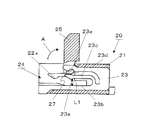
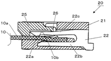
図1及び図2はこの発明に係わる電気コネクタ20の要部断面図で、図1は第2のコンタクト23を詳細に示し、また図2は第1のコンタクト22を詳細に示している。
1 and 2 are cross-sectional views of the main part of the
この電気コネクタ20も、従来と同様に、断面略矩形状のハウジング21と、図面垂直方向へ向け、このハウジング21内に交互に隣接して配設された第1と第2のコンタクト22、23とから構成されている。
The
この第1と第2の各コンタクト22、23のうち、図2に示す第1のコンタクト22は、基板挿入口24に隣接して形成された一つの接点22aと、互いに連結し側面が略U字形に形成された第1と第2のコンタクト片22b、22cとにより形成され、前記接点22aは第2のコンタクト片22cの先端に形成されている。
Of the first and
一方、図1に示すように、第2のコンタクト23は、基板挿入口24から離間するハウジング21の奥側の位置に形成された一つの接点23aと、互いに連結し側面が略U字形に形成され第1と第2のコンタクト片23b、23cと、この第2のコンタクト片23cから分岐して略U字形に折り曲げて形成された第3のコンタクト片23dとから形成され、全体としてその側面の形状が略E字形状をしている。なお、上述した第2のコンタクト23の接点は第2のコンタクト片23cの先端に形成されている。
On the other hand, as shown in FIG. 1, the
一方、この図1に示すように電気コネクタ20の基板挿入口24には、その上面を開閉自在に構成するアクチュエータ25が配設されている。
On the other hand, as shown in FIG. 1, an
このアクチュエータ手段25は、ハウジング21の側壁に嵌挿する図示せぬ軸を中心に矢印Aで示すように回動自在に支承されている。
The actuator means 25 is rotatably supported as indicated by an arrow A about a shaft (not shown) that is fitted into the side wall of the
この、アクチュエータ25には、図2で示すように、当該アクチュエータ25が一方向(反時計方向)へ回転した際に接点22aが形成された第2のコンタクト片22cの上面を押圧する突起形状の第1のカム26と、図1で示すように、同じくアクチュエータ25が一方向(反時計方向)へ回転した際に、接点23aが形成された第2のコンタクト片23cの上面を押圧する略達磨形状の第2のカム27とが形成されている。なお、この第2のカム27は図1で示すように、第3のコンタクト片23dの先端下面に形成された円弧形状の切り欠23e内に嵌挿支持されている。
As shown in FIG. 2, the
なお、図1及び図2で示すように、アクチュエータ25を拡開した初期位置では、図1のように第2のコンタクト23の接点23aと第1のコンタクト片23bとの間の間隔L1は後述する印刷配線基板の板厚よりも大きく設定され、また図2で示すように、第1のコンタクト22の接点22aと第1のコンタクト片22bとの間隔L2も後述する印刷配線基板の板厚よりも大きく設定されている。
As shown in FIGS. 1 and 2, at the initial position where the
また、第1のコンタクト22の接点22aと基板挿入口24の下面24aとの間隔L3も後述する印刷配線基板の板厚よりも大きく設定されている。
Further, the distance L3 between the
一方、図3で示すように、FPC(フレキシブル印刷配線基板)10は、その上面10aの先端側と、やや奥まった位置にそれぞれ第1と第2の接続端子10b、10cが形成されている。
On the other hand, as shown in FIG. 3, the FPC (flexible printed wiring board) 10 has first and
このような構造の電気コネクタ20によると、図1及び図2に示すアクチュエータ25の初期位置では、第2のコンタクト23の接点23aと第1のコンタクト片23bとの間隔L1、および第1のコンタクト22の接点22aと第1のコンタクト片22bとの間隔L2、および第1のコンタクト22の接点22aと基板挿入口24の下面24aとの間隔L3はいずれも印刷配線基板の板厚よりも大きく設定されているので、図5で示すように、FPC(フレキシブル印刷配線基板)10を挿入すると、当該FPC10の先端10dはハウジング21内の前方に位置する第1のコンタクト22の接点22aと第1のコンタクト片22bとの間、および第1のコンタクト22の接点22aと基板挿入口24の下面24aとの間をスムーズに嵌装し、また図4で示すように、第2のコンタクト23の接点23aと第1のコンタクト片23bとの間をスムーズに嵌挿して、全体としていわゆるZIF(ZERO INSERTION FORCE)構造のコネクタとなる。
According to the
このように、FPC10の先端10dが第1のコンタクト22の接点22aと第1のコンタクト片22bとの間、および第2のコンタクト23の接点23aと第1のコンタクト片23bとの間をスムーズに嵌挿した後、図6、図7の矢印で示すように、アクチュエータ25を反時計方向へ回転させると当該アクチュエータ25の第1のカム26が図7で示すように第1のコンタクト22の第2のコンタクト片22cの上面を押圧し、また図6で示すように第2のカム27が第2のコンタクト23の第2のコンタクト片23cの上面をそれぞれ押圧する。
In this way, the
この図6、7で示すように、アクチュエータ25の第1のカム26が第1のコンタクト22の第2のコンタクト片22cの上面を押圧し、また第2のカム27が第2のコンタクト23の第2のコンタクト片23cの上面を押圧すると、図9で示すように第2のコンタクト片22cの上面を押圧する第1のカム26の押圧力により接点22aがFPC10の第1の接続端子10bに当接し、また図8で示すように、第2のコンタクト片23cの上面を押圧する第2のカム27の押圧力により接点23aがFPC10の第2の接続端子10cに当接する。
As shown in FIGS. 6 and 7, the
このため、FPC10の上面10aに形成された第1と第2の各接続端子10b、10cは、対応する第1のコンタクト22の接点22aと第2のコンタクト23の接点23aとに、それぞれ確実に電気的に接続されることとなる。
Therefore, the first and
従って、上述した電気コネクタ20によると、接点22aが基板挿入口24に隣接する位置に形成された第1のコンタクト22に対しても、またハウジング21の奥側に接点23aが形成された第2のコンタクト23に対してもいずれもZIF(ZERO INSERTION FORCE)構造となり、電気コネクタ20に対するFPC10の装着作業が極めて簡単となるだけでなく、アクチュエータ25に形成された第1と第2のカム26、27により、電気コネクタ20の各接点22a、23aとFPC10の上面に形成された各接続端子10b、10cとの確実な電気的接続が得られることとなる。
Therefore, according to the above-described
この発明は、FPCの装着が容易で、しかもFPCの引き回しの自由度を向上させるようにした電気コネクタに適している。 The present invention is suitable for an electrical connector in which FPC can be easily attached and the degree of freedom of FPC routing is improved.
10…印刷配線基板
10b、10c…接続端子
20…電気コネクタ
21…ハウジング
22…第1のコンタクト
23…第2のコンタクト
22a、23a…接点
22b、23b…第1のコンタクト片
22c、23c…第2のコンタクト片
23d…第3のコンタクト片
24…基板挿入口
25…アクチュエータ
26…第1のカム
27…第2のカム
DESCRIPTION OF
Claims (1)
前記第1のコンタクトは、第1のコンタクト片と、該第1のコンタクト片に連結し前記アクチュエータ側に向けて略U字形に曲げられるとともに前記一方の接続端子と接触する接点が形成された第2のコンタクト片からなり、
前記第2のコンタクトは、第1のコンタクト片と、該第1のコンタクト片に連結し前記アクチュエータ側に向けて略U字形に曲げられるとともに前記フレキシブル印刷配線基板の他方の接続端子と接触する接点が形成された第2のコンタクト片と、該第2のコンタクト片からさらに分岐し前記アクチュエータ側に向けて略U字形に曲げられた第3のコンタクト片からなり、
前記アクチュエータには、回動した際に前記第1のコンタクトの前記接点が形成された第2のコンタクト片を押圧する第1のカムと前記第2のコンタクトの前記接点が形成された第2のコンタクト片を押圧する第2のカムとがそれぞれ形成され、
また前記第1のコンタクトの第2のコンタクト片に形成された前記接点と前記第1のコンタクトの前記第1のコンタクト片との間隔、および前記第2のコンタクトの第2のコンタクト片に形成された前記接点と前記第2のコンタクトの前記第1のコンタクト片との間隔は、いずれも前記挿入されるフレキシブル印刷配線基板の板厚よりも大きいことを特徴とする電気コネクタ。 A housing in which a board insertion port for inserting a flexible printed wiring board is formed in the front, and first and second contacts arranged in parallel in the housing, the insertion at a position adjacent to the board insertion port A first contact formed with a contact point that contacts one of the connection terminals of the flexible printed wiring board, and a position of the inserted flexible printed wiring board at a position on the back side of the housing that is separated from the board insertion port. A second contact formed with a contact point in contact with the other connection terminal; and a first contact for connecting each connection terminal of the flexible printed circuit board inserted and supported rotatably on the housing about an axis. And an electrical connector having an actuator that presses against each contact of the second contact,
The first contact includes a first contact piece and a first contact piece that is connected to the first contact piece and is bent in a substantially U shape toward the actuator and has a contact point that contacts the one connection terminal. Consisting of two contact pieces,
The second contact is a first contact piece, a contact connected to the first contact piece, bent into a substantially U shape toward the actuator, and contacted with the other connection terminal of the flexible printed circuit board And a third contact piece that is further branched from the second contact piece and bent into a substantially U shape toward the actuator side,
The actuator has a first cam that presses a second contact piece on which the contact of the first contact is formed and a second contact on which the contact of the second contact is formed. A second cam for pressing the contact piece is formed respectively .
Further, the distance between the contact point formed on the second contact piece of the first contact and the first contact piece of the first contact, and the second contact piece of the second contact. Further, the electrical connector is characterized in that the distance between the contact and the first contact piece of the second contact is larger than the thickness of the flexible printed wiring board to be inserted.
Priority Applications (1)
| Application Number | Priority Date | Filing Date | Title |
|---|---|---|---|
| JP2003358063A JP4315331B2 (en) | 2003-10-17 | 2003-10-17 | Electrical connector |
Applications Claiming Priority (1)
| Application Number | Priority Date | Filing Date | Title |
|---|---|---|---|
| JP2003358063A JP4315331B2 (en) | 2003-10-17 | 2003-10-17 | Electrical connector |
Publications (2)
| Publication Number | Publication Date |
|---|---|
| JP2005123075A JP2005123075A (en) | 2005-05-12 |
| JP4315331B2 true JP4315331B2 (en) | 2009-08-19 |
Family
ID=34614761
Family Applications (1)
| Application Number | Title | Priority Date | Filing Date |
|---|---|---|---|
| JP2003358063A Expired - Fee Related JP4315331B2 (en) | 2003-10-17 | 2003-10-17 | Electrical connector |
Country Status (1)
| Country | Link |
|---|---|
| JP (1) | JP4315331B2 (en) |
Families Citing this family (4)
| Publication number | Priority date | Publication date | Assignee | Title |
|---|---|---|---|---|
| JP4750529B2 (en) * | 2005-10-25 | 2011-08-17 | 京セラエルコ株式会社 | connector |
| JP4938303B2 (en) * | 2005-12-16 | 2012-05-23 | 日本圧着端子製造株式会社 | connector |
| JP4975771B2 (en) * | 2009-02-19 | 2012-07-11 | ヒロセ電機株式会社 | Flat conductor electrical connector |
| KR20130116893A (en) * | 2010-11-18 | 2013-10-24 | 에프씨아이 커넥터즈 싱가포르 피티이 엘티디. | Flexible printed circuit board connector |
-
2003
- 2003-10-17 JP JP2003358063A patent/JP4315331B2/en not_active Expired - Fee Related
Also Published As
| Publication number | Publication date |
|---|---|
| JP2005123075A (en) | 2005-05-12 |
Similar Documents
| Publication | Publication Date | Title |
|---|---|---|
| US7275954B2 (en) | Connector establishing a stable connection between a contact of the connector and a connection object | |
| JP4542525B2 (en) | Cable connector | |
| JP4479989B2 (en) | connector | |
| JP4073766B2 (en) | connector | |
| CN104425918A (en) | Electric connector | |
| JP2002252067A (en) | Electric connector | |
| JP4707610B2 (en) | Cable connector | |
| JP2004178931A (en) | Electric connector for flat flexible cable | |
| WO2008033319A1 (en) | Stacked fpc connector | |
| JP4558562B2 (en) | connector | |
| US9590335B1 (en) | Connector | |
| JP4927454B2 (en) | connector | |
| JP2007265825A (en) | Relay connector | |
| JP2006338955A (en) | Connector for flat cable | |
| JP3125545U (en) | Electrical connector for FPC | |
| JP4315331B2 (en) | Electrical connector | |
| JP2004206987A (en) | Connector | |
| JPH11339901A (en) | Electric connector for flexible substrate | |
| JP4135902B2 (en) | Electrical connector | |
| JP2003045526A (en) | Electrical connector | |
| JP4442195B2 (en) | Electrical connection structure | |
| JP5344285B2 (en) | Connector device | |
| JP4644719B2 (en) | connector | |
| JP6514822B2 (en) | connector | |
| JP6514823B2 (en) | connector |
Legal Events
| Date | Code | Title | Description |
|---|---|---|---|
| A621 | Written request for application examination |
Free format text: JAPANESE INTERMEDIATE CODE: A621 Effective date: 20060901 |
|
| A977 | Report on retrieval |
Free format text: JAPANESE INTERMEDIATE CODE: A971007 Effective date: 20081212 |
|
| A131 | Notification of reasons for refusal |
Free format text: JAPANESE INTERMEDIATE CODE: A131 Effective date: 20081224 |
|
| A521 | Written amendment |
Free format text: JAPANESE INTERMEDIATE CODE: A523 Effective date: 20090216 |
|
| A131 | Notification of reasons for refusal |
Free format text: JAPANESE INTERMEDIATE CODE: A131 Effective date: 20090331 |
|
| A521 | Written amendment |
Free format text: JAPANESE INTERMEDIATE CODE: A523 Effective date: 20090410 |
|
| TRDD | Decision of grant or rejection written | ||
| A01 | Written decision to grant a patent or to grant a registration (utility model) |
Free format text: JAPANESE INTERMEDIATE CODE: A01 Effective date: 20090508 |
|
| A01 | Written decision to grant a patent or to grant a registration (utility model) |
Free format text: JAPANESE INTERMEDIATE CODE: A01 |
|
| A61 | First payment of annual fees (during grant procedure) |
Free format text: JAPANESE INTERMEDIATE CODE: A61 Effective date: 20090514 |
|
| R150 | Certificate of patent or registration of utility model |
Ref document number: 4315331 Country of ref document: JP Free format text: JAPANESE INTERMEDIATE CODE: R150 Free format text: JAPANESE INTERMEDIATE CODE: R150 |
|
| FPAY | Renewal fee payment (event date is renewal date of database) |
Free format text: PAYMENT UNTIL: 20120529 Year of fee payment: 3 |
|
| FPAY | Renewal fee payment (event date is renewal date of database) |
Free format text: PAYMENT UNTIL: 20120529 Year of fee payment: 3 |
|
| FPAY | Renewal fee payment (event date is renewal date of database) |
Free format text: PAYMENT UNTIL: 20120529 Year of fee payment: 3 |
|
| FPAY | Renewal fee payment (event date is renewal date of database) |
Free format text: PAYMENT UNTIL: 20120529 Year of fee payment: 3 |
|
| S111 | Request for change of ownership or part of ownership |
Free format text: JAPANESE INTERMEDIATE CODE: R313111 |
|
| FPAY | Renewal fee payment (event date is renewal date of database) |
Free format text: PAYMENT UNTIL: 20120529 Year of fee payment: 3 |
|
| R360 | Written notification for declining of transfer of rights |
Free format text: JAPANESE INTERMEDIATE CODE: R360 |
|
| FPAY | Renewal fee payment (event date is renewal date of database) |
Free format text: PAYMENT UNTIL: 20120529 Year of fee payment: 3 |
|
| R250 | Receipt of annual fees |
Free format text: JAPANESE INTERMEDIATE CODE: R250 |
|
| FPAY | Renewal fee payment (event date is renewal date of database) |
Free format text: PAYMENT UNTIL: 20130529 Year of fee payment: 4 |
|
| R370 | Written measure of declining of transfer procedure |
Free format text: JAPANESE INTERMEDIATE CODE: R370 |
|
| S111 | Request for change of ownership or part of ownership |
Free format text: JAPANESE INTERMEDIATE CODE: R313111 |
|
| FPAY | Renewal fee payment (event date is renewal date of database) |
Free format text: PAYMENT UNTIL: 20130529 Year of fee payment: 4 |
|
| R350 | Written notification of registration of transfer |
Free format text: JAPANESE INTERMEDIATE CODE: R350 |
|
| FPAY | Renewal fee payment (event date is renewal date of database) |
Free format text: PAYMENT UNTIL: 20130529 Year of fee payment: 4 |
|
| FPAY | Renewal fee payment (event date is renewal date of database) |
Free format text: PAYMENT UNTIL: 20130529 Year of fee payment: 4 |
|
| FPAY | Renewal fee payment (event date is renewal date of database) |
Free format text: PAYMENT UNTIL: 20130529 Year of fee payment: 4 |
|
| FPAY | Renewal fee payment (event date is renewal date of database) |
Free format text: PAYMENT UNTIL: 20140529 Year of fee payment: 5 |
|
| R250 | Receipt of annual fees |
Free format text: JAPANESE INTERMEDIATE CODE: R250 |
|
| R250 | Receipt of annual fees |
Free format text: JAPANESE INTERMEDIATE CODE: R250 |
|
| R250 | Receipt of annual fees |
Free format text: JAPANESE INTERMEDIATE CODE: R250 |
|
| R250 | Receipt of annual fees |
Free format text: JAPANESE INTERMEDIATE CODE: R250 |
|
| R250 | Receipt of annual fees |
Free format text: JAPANESE INTERMEDIATE CODE: R250 |
|
| R250 | Receipt of annual fees |
Free format text: JAPANESE INTERMEDIATE CODE: R250 |
|
| LAPS | Cancellation because of no payment of annual fees |