JP4314014B2 - Camera with built-in flash - Google Patents
Camera with built-in flash Download PDFInfo
- Publication number
- JP4314014B2 JP4314014B2 JP2002317413A JP2002317413A JP4314014B2 JP 4314014 B2 JP4314014 B2 JP 4314014B2 JP 2002317413 A JP2002317413 A JP 2002317413A JP 2002317413 A JP2002317413 A JP 2002317413A JP 4314014 B2 JP4314014 B2 JP 4314014B2
- Authority
- JP
- Japan
- Prior art keywords
- flash
- camera
- built
- strobe
- waiting time
- Prior art date
- Legal status (The legal status is an assumption and is not a legal conclusion. Google has not performed a legal analysis and makes no representation as to the accuracy of the status listed.)
- Expired - Fee Related
Links
Images


Description
【0001】
【発明の属する技術分野】
本発明は、ストロボ内蔵カメラに関し、特に、追加部材無しで、暗黒時のフレーミング補助を行うことが可能なストロボ内蔵カメラに関する。
【0002】
【従来の技術】
従来のストロボ内蔵カメラにおけるストロボ装置(フラッシュ装置)のなかには、本発光のほかにプリ発光(テスト発光)の機能を備えたものがある。本発光がストロボ撮影時の露光のために行われるのに対し、プリ発光は、本発光によって被写体に生じる陰影状態(照明状態,反射の様子,被写体の影の方向・大きさ等)を、ファインダを通して撮影前に確認するために行う。
【0003】
プリ発光は、ストロボ装置を小光量で間欠発光させることにより行う。即ち、本発光に補助照明として使用されるストロボ発光部をそのまま用い、発光量や発光タイミング,発光周期をコントロールすることで、プリ発光モードに応じた間欠発光によりプリ発光を行う。
プリ発光モードとしては、例えば、ポートレートモード(周波数2Hz,発光回数3回,発光時間1秒間)やマクロモード(周波数40Hz,発光回数160回,発光時間4秒間)がある。
【0004】
ところで、近年、市販のオートフォーカス一眼レフカメラのなかには、アイコントロール機能を有するものが知られている。この機能によれば、視線入力による測距点選択等が可能である。
【0005】
即ち、使用者がファインダを覗いてファインダ視野内に設けられている複数のフォーカスエリアのうちの1つを見ながら、シャッターボタンを半押しする。すると、使用者の視線を視線検出用CCD(Charge Coupled Device)エリアセンサが検知し、その検知された視線位置にあるフォーカスエリアが選択される。そして、その選択されたフォーカスエリアでのピント状態が検出され、その検出結果に基づいたレンズ駆動によって、オートフォーカスが行われる。
【0006】
しかし、前述のプリ発光中にオートフォーカスの起動を指示する操作(シャッターボタンの半押し,接眼検知動作等)が行われると、撮影者の意図していない被写体(プリ発光中に合焦状態にある主被写体以外の被写体)にピントを合わせるようにオートフォーカス動作が行われてしまい、その結果、被写体像のピント状態が変化してしまう場合がある。
【0007】
かかるオートフォーカス動作としては、例えば、大きくピントのズレた位置にある被写体(主被写体の背景等)にピントを合わせるために行われるレンズ駆動動作や、低コントラストの被写体にピントを合わせるために行われるローコントラストスキャン動作等が挙げられる。
このように被写体像のピント状態が変化すると、ファインダを通した前記陰影状態の確認作業が中断されるという問題が生じる。
【0008】
また、プリ発光中、使用者はファインダ内を覗きながら被写体全体を捉えようとするので、常に主被写体を的確に捉えているとは限らない。従って、視線入力による測距点選択が可能な前記カメラにおいて、プリ発光中にオートフォーカスの起動を指示する前記視線検知が行われると、上記と同様、撮影者の意図していない被写体にピントを合わせるようにオートフォーカス動作が行われてしまう。その結果、被写体像のピント状態が変化してしまう場合がある。
従って、この場合もファインダを通した前記陰影状態の確認作業が中断されるという問題が生じる。
【0009】
前記陰影状態の確認作業を中断させる原因は、オートフォーカス動作によるピント状態の変化に限らない。例えば、ズーミング,2焦点以上の焦点切換えによって焦点距離が変化した場合や、トリミング撮影,パノラマ撮影時にファインダ視野の切換えを行った場合等に生じる画角変化のように、ファインダを通して確認される被写体像状態がプリ発光中に変化すれば、上記確認作業は中断されてしまう。
【0010】
また、カメラが、オートフォーカスによって得られた撮影距離に基づいて最適な撮影倍率となるようにズーミングを行う機能(オートズーム機能)を備えている場合には、オートフォーカスにズーミングが連動してしまうため、ピント状態変化に画角変化が伴って被写体像状態が変化することになる。
【0011】
以上の問題点を解決するために、プリ発光中に被写体像状態の設定を指示する操作が行われても、本発光によって被写体に生じる陰影状態を、ファインダを通して撮影前に確認する作業が中断されないようにしたカメラシステムが提案されている(特許文献1参照)。
【0012】
そして、この従来技術の発明では、プリ発光中にピント状態の設定を指示するオートフォーカス操作が行われても、マイコン(制御手段)が、プリ発光中の(ファインダで確認される)ピント状態が変化しないように、フォーカス駆動部のオートフォーカス動作を制御するようにしている。
【0013】
【特許文献1】
特開平8−190136号公報 (第1頁)
【0014】
【発明が解決しようとする課題】
しかしながら、前記従来技術では、被写体の陰影を確認する為に一連の撮影動作とは無関係のプリ発光や、赤目防止のための本発光前のプリ発光は行われていたものの、一連の撮影動作の中で、プリ発光を行い、フレーミング変更時間経過後、一連の撮影動作を行うことはしていない。
【0015】
ここに、フレーミングとは、被写体のファインダ内の配置を、確認することをいう。このフレーミング変更時間を確保できれば、フレーミングのズレによる失敗写真を無くすことができる。
【0016】
また、ストロボ(ストロボ装置)を使用しない場合(暗黒時や暗黒時に近い状態)のフレーミングを補助するためのプリ発光はなかった。このようなことが可能になれば、フレーミングのズレによる失敗写真を無くすことができる。
【0017】
本発明は、上記の事情にかんがみなされたもので、追加部材無しで、暗黒時のフレーミング補助を行うことが可能なストロボ内蔵カメラの提供を目的とする。
【0018】
【課題を解決するための手段】
上記目的を達成するため請求項1記載の発明は、プリ発光と通常発光との双方の発光機能を備えたストロボ内蔵カメラにおいて、撮影時の測光結果が所定輝度未満の場合には、該測光結果の輝度に応じて暗いほど多くの回数でプリ発光を行い、ファインダを介して見た被写体のフレーミングを修正するために1秒程度の待ち時間を経過した後に測光、測距した結果で撮影処理を行うフレーミング補助機能を有する構成としてある。
【0019】
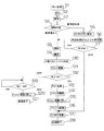
このようにすれば、例えば、図4のステップS1→ステップS4(基準値未満)→ステップS5→ステップS6のように、撮影時の測光結果が所定輝度未満の場合には、プリ発光を行い、所定時間経過後、通常の撮影処理を行う構成としてあるので、ファインダを介して見た被写体が暗くて良く確認できない場合には、確保した所定時間の間に被写体のファインダ上の配置を十分確認できる。
【0020】
従って、ファインダ上の被写体配置未確認によるピンぼけや露出オーバー(アンダー)等の失敗写真を防止できる。また、プリ発光により瞳孔の開きを小さくするので、いわゆる赤目を防止できる。
【0027】
このようにすれば、例えば、図5に示すように、ラフ発光の結果により輝度レベルに応じてプリ発光の発光回数を変更できるので、例えば1回のプリ発光では被写体を十分確認できない場合でも、数回プリ発光を繰り返すことにより被写体を十分確認できる。従って、失敗写真が無くなる。
【0031】
次に請求項2記載の発明は、請求項1記載のストロボ内蔵カメラにおいて、前記プリ発光後の待ち時間を変更可能にした構成としてある。
このようにすれば、プリ発光後の待ち時間をユーザの好みに応じて変更できるので、ユーザが納得したフレーミングを行うことができる。
【0032】
次に請求項3記載の発明は、請求項2記載のストロボ内蔵カメラにおいて、前記プリ発光後の待ち時間を待ち時間格納手段に格納しておき、プリ発光後の待ち時間を調整可能にした構成としてある。
【0033】
このようにすれば、待ち時間格納手段(例えば図1のEEPROM部30)のプリ発光後の待ち時間の格納値を変更できるので、ユーザが納得したフレーミングを行うことができる。
【0034】
次に請求項4記載の発明は、請求項2記載のストロボ内蔵カメラにおいて、前記プリ発光後の待ち時間を、調整可能にするモードを構成としてある。
このようにすれば、調整可能のモードとしては、例えば既存のズーム釦(zoomT,W釦)を使用するので追加の釦が不要となり、カメラのコストアップを抑制し、且つ使い勝手良くプリ発光の光量を設定できる。
【0035】
次に請求項5記載の発明は、請求項2記載のストロボ内蔵カメラにおいて、前記プリ発光後の待ち時間中に、ストロボ用蓄電手段の追加充電を行う構成としてある。
このようにすれば、プリ発光後の待ち時間中にストロボ用蓄電手段(図示省略のコンデンサ)の追加充電を行うので、本発光の際の発光量低下を抑制できる。
【0036】
次に請求項6記載の発明は、請求項5記載のストロボ内蔵カメラにおいて、前記フレーミング補助機能が有効な場合には、通常の充電レベルより高い充電レベルを設定する構成としてある。
このようにすれば、フレーミング補助機能が有効な場合には、通常より高い充電レベルで充電するので、本発光の際の発光量低下を抑制できる。
【0037】
次に請求項7記載の発明は、請求項5〜請求項6記載のストロボ内蔵カメラにおいて、前記フレーミング補助機能が有効で前記プリ発光が実行された後、撮影釦半押し用のスイッチがОFFされている場合には、撮影を中断し、ストロボ用蓄電手段の充電を行う構成としてある。
【0038】
このようにすれば、例えば図4のステップS1→ステップS4:基準値未満→ステップS5→ステップS7:ОFF→ステップS17→ステップS18の処理を行うので、ストロボ用蓄電手段(コンデンサ)にストロボ用の充電が可能となり、ストロボ発光に十分な光量を確保できる。
【0039】
【発明の実施の形態】
以下、本発明を図示の実施形態に基づいて説明する。図1は本実施形態のブロック図である。
図1に示すように、ストロボ内蔵カメラSNは、制御部10と、ストロボ部20と、EEPROM部30と、表示部40と、第1〜第4のスイッチ51〜54とを備えてなる。
【0040】
制御部10は、ストロボ内蔵カメラSNの全機能を制御し、マイクロコンピュータ(マイコン)などからなる(後述)。ストロボ部20は、補助照明がなく、適正な撮影を行うことが困難な被写体輝度の場合に、補助的な照明を行うための装置である(後述)。
【0041】
EEPROM部30は不揮発性メモリであり、標準的な発光時間(または発光回数),フレーミング修正時間のパラメータ等を格納する。
なお、前記パラメータは、図2に示すように、ユーザが設定変更可能にしてもよいし(カスタマイズモード)、サービスセンタなどでカスタマイズする方法をとってもよい。図2は、パラメータ修正モードの例を示す図である。
表示部40は液晶等からなり、フィルムカウンタに使用する(図2参照)。ユーザが被写体の撮影部分を確認するのに使用する。
【0042】
第1のスイッチ(RL1)51および第2のスイッチ52(RL2)は、撮影を行うためのスイッチである。
第1のスイッチ51は「撮影釦半押し用」のスイッチであり、第1のスイッチ51が押されると、測光,測距,レンズ駆動(フォーカシング)等を行う。
続いて、「撮影釦押し込み用」の第2のスイッチ52が押されると、シャッタ開閉,レンズ駆動(初期位置に復帰),フィルム給送,ストロボ充電(ストロボ禁止モード時以外)を行い、一連の撮影動作を終了する。
【0043】
第3のスイッチ53はズーム用スイッチであり、53aは望遠用(zoom T)スイッチであり、53bはワイド用(zoom W)スイッチである(図2参照)。第4のスイッチ54は、EEPROM部30のパラメータを修正する場合に使用するスイッチである。
【0044】
次に、ストロボ部20に対する制御部10による制御を説明する。
ストロボ部20は撮影時の被写体照明以外の目的(即ち、プリ発光)にも使用するため、あらかじめ決められた2種類の高い電圧レベルと低い電圧レベルに対応した発光量に制御する。
【0045】
即ち、図3に示すように、プリ発光機能(フレーミング補助機能)が有効な場合には、プリ発光を行っても以後行われる通常のストロボ撮影に支障の無い、通常の充電レベルより高い電圧レベルを設定する。逆に、プリ発光機能が無効な場合には、通常の撮影可能な規定の発光光量が確保できるレベルに設定する。
充電レベルに関しては、通常の撮影可能レベルが300V、フルチャージレベルが320Vと仮定すると、その間に設定する。即ち、プリ発光量の設定状態により、失われる分の充電電圧を補うことが可能な充電レベルに設定する。フレーミング用の待ち時間時の充電も同様に行う。
なお、制御部10が発光コントロール端子を制御(必要時間アクティブレベルにする)することで、発光光量を自在にコントロール可能な構成となっている。
【0046】
次に、図4〜図5を参照しつつ、本実施形態の動作を説明する。
図4は本実施形態のフローチャート、図5は発行時間(回数),待ち時間の変化をさせる例を説明する図である。
【0047】
図4に示すように、第1のスイッチ(RL1)51 がONされると(ステップS1)、ストロボ発光,レンズ駆動等に使用するバッテリのチェック(BC)が行われ(ステップS2)、測光が行われる(ステップS3)。
この測光動作は測光エリア全体の輝度(被写体輝度)をラフに測定する為のものである。測光センサが、複数の部分に分割されている場合は、可能な限り周辺部のセンサで判定を行うか、または、画面全体の平均的な輝度を測光する。
【0048】
ステップS3における輝度レベルの測光結果が、基準値未満(ここでは、LV3以下(図5参照))の場合は、ファインダ(図示省略)により被写体全体の状況をつかめる状態に無いと判断し(ステップS4:基準値未満)、ストロボ部20を短時間発光(プレ発光)させ、被写体の照明を行う(ステップS5)。
【0049】
ここの発光時間は、被写体の輝度に応じて、図5に示すように、より暗い場合は(例えば、輝度レベル(LV)0未満)発光時間を長く(または光量を同じにして短時間発光の発光回数を多く)する。
比較的明るい場合は(例えば、輝度レベル(LV)4)、発光時間を短く(または発光回数を少なく)する。発光時間の長短等は、前述のようにEEPROM部30にパラメータとして、格納されている。
【0050】
ストロボ発光後、通常の撮影動作に移行する前に、標準で1秒程度の待ち時間を設けて、その時間をフレーミング修正時間(ユーザがフレーミングを修正するために確保する時間)とする。フレーミング修正時間の長短等は、前述のようにEEPROM部30にパラメータとして格納されている。
【0051】
また、フレーミング修正時間を利用して、ストロボ用コンデンサの追加充電を行い(ストロボ充電)、発光によって失われたエネルギーを補う方式をとれば、実撮影時の光量をより大きくすることが可能である(ステップS6)。
【0052】
プリ発光後、第1のスイッチ51が離されていれば(ステップS7:ОFF)、撮影動作を中断し、直ちにストロボ充電を行うことにより(ステップS17)、次のフレーミングを行うことが可能になる(ステップS18)。
【0053】
フレーミング修正時間の後であっても、第1のスイッチ51が押されていれば、正規の測光,測距,フォーカシング等の撮影動作を行う(ステップS7:ОN)。
即ち、測光を行い(ステップS8)、測距を行い(ステップS9)、必要に応じてストロボ充電を行い(ステップS10)、フォーカス駆動を行う(ステップS11)。
【0054】
そして、「撮影釦押し込み用」の第2のスイッチ(RL2)52が押されると(ステップS12:ОN)、以下のステップS14〜ステップS18のRL2処理を行う(ステップS13)。
即ち、シャッタの開閉を行い(ステップS14)、フォーカス駆動を行い(ステップS15)、フィルム給送を行い(ステップS16)、ストロボ充電を行い(ステップS17)、一連の撮影処理を終了する(ステップS18)。
【0055】
前記ステップS12において、第2のスイッチ(RL2)52がОFFの場合には(ステップS12:ОFF)、第1のスイッチ(RL1)51がОFFであれば(ステップS19:ОFF)、フォーカス駆動を戻し(ステップS20)、処理を終了する(ステップS21)。
【0056】
以上の構成および処理により、従来、オートフォーカス(AF)の測距能力,ストロボの照明能力としては充分に撮影可能な範囲内の被写体であるにも拘わらず、ファインダで良く被写体を確認できない輝度であるため、充分なフレーミングが不可能であったり、AF測距範囲を外したりして、ピンぼけや露出オーバー(アンダー)等の失敗写真となっていた不具合を防止できる。
【0057】
また、従来の構成に、部品を追加する必要がなく、一連の撮影の流れの中で自然な操作感を得ることができるので、コストをアップすることなく実質的な使い勝手を向上させることが可能となる。
【0058】
また、発光時間(回数),待ち時間等のパラメータデータを不揮発性メモリ(EEPROM)に格納しておき、例えば、パラメータ修正モードを設けて、パラメータ設定モードが設定されている場合は、ズーム釦等によりパラメータのアップダウンができるような構成とすることで、各ユーザの使い勝手に合わせて、より実用的な構成とすることができる。
【0059】
また、一連の撮影の流れの中で、被写体が非常に暗い場合には、まずラフなフレーミングを行い、プリ発光により被写体を再確認し、フレーミングを修正後、本撮影を行うことができる。
【0060】
従って、従来被写体が暗い場合にフレーミングがいい加減になり、ひどい場合には、AFフレームから被写体がずれてピンぼけ写真となる事態を減らすことが可能である。また、ストロボを使用しない場合にも、フレーミング補助機能を使用することが可能となり、第1のスイッチ51のON-OFF を繰り返すことにより、何度でもフレーミングを修正し、正確な写真撮影を行うことが可能になる。
【0061】
なお、前記実施形態では銀塩フィルムの場合を説明したが、ファインダに液晶等からなる表示装置を備えたデジタルカメラにおいても、本発明を適用可能であるのは勿論である。
【0062】
【発明の効果】
以上説明したように本発明によれば、以下の効果を発揮することができる。
請求項1記載の発明によれば、撮影時の測光結果が所定輝度未満の場合には、該測光結果の輝度に応じて暗いほど多くの回数でプリ発光を行い、ファインダを介して見た被写体のフレーミングを修正するために1秒程度の待ち時間を経過した後に測光、測距した結果で撮影処理を行うフレーミング補助機能を有する構成としてあるので、ファインダを介して見た被写体が暗くて良く確認できない場合には、確保した所定時間の間に被写体のファインダ上の配置を十分確認できる。
【0063】
従って、ファインダ上の被写体配置未確認によるピンぼけや露出オーバー(アンダー)等の失敗写真を防止できる。また、プリ発光により瞳孔の開きを小さくするので、いわゆる赤目を防止できる。
【0066】
さらに、請求項1記載の発明によれば、例えば1回のプリ発光では被写体を十分確認できない場合でも、数回プリ発光を繰り返すことにより被写体を十分確認できる。従って、失敗写真が無くなる。
【0069】
請求項2記載の発明によれば、プリ発光後の待ち時間をユーザの好みに応じて変更できるので、ユーザが納得したフレーミングを行うことができる。
請求項3記載の発明によれば、待ち時間格納手段のプリ発光後の待ち時間の格納値を変更できるので、ユーザが納得したフレーミングを行うことができる。
【0070】
請求項4記載の発明によれば、プリ発光後の待ち時間を調整可能にするモードとして、例えば既存のズーム釦を使用するので、追加の釦が不要となり、カメラのコストアップを抑制し、且つ使い勝手良くプリ発光の光量を設定できる。
【0071】
請求項5記載の発明によれば、プリ発光後の待ち時間中にストロボ用蓄電手段の追加充電を行うので、本発光の際の発光量低下を抑制できる。
請求項6記載の発明によれば、フレーミング補助機能が有効な場合には、通常より高い充電レベルで充電するので、本発光の際の発光量低下を抑制できる。
【0072】
請求項7記載の発明によれば、フレーミング補助機能が有効で前記プリ発光が実行された後、撮影釦半押し用のスイッチがОFFされている場合には、撮影を中断し、ストロボ用蓄電手段の充電を行う構成としてあるので、ストロボ用蓄電手段にストロボ用の充電が可能となり、ストロボ発光に十分な光量を確保できる。
【図面の簡単な説明】
【図1】本発明の実施形態のブロック図である。
【図2】同実施形態における、パラメータ修正モードの例を示す図である。
【図3】同実施形態における、ストロボ用コンデンサへの充電レベルを説明する図である。
【図4】同実施形態における、フローチャートである。
【図5】同実施形態における、発光時間(回数),待ち時間の変化をさせる例を説明する図である。
【符号の説明】
SN ストロボ内蔵カメラ
10 制御部
20 ストロボ部
30 EEPROM部
40 表示部
51 第1のスイッチ
52 第2のスイッチ
53 第3のスイッチ
53a 第3のスイッチにおける望遠用スイッチ
53b 第3のスイッチにおけるワイド用スイッチ
54 第4のスイッチ[0001]
BACKGROUND OF THE INVENTION
The present invention relates to a camera with a built-in strobe, and more particularly to a camera with a built-in strobe that can perform framing assistance in the dark without an additional member.
[0002]
[Prior art]
Some strobe devices (flash devices) in conventional cameras with a built-in strobe have a pre-flash function (test flash) in addition to the main flash. While the main flash is used for exposure during flash photography, the pre-flash uses the viewfinder to indicate the shaded state (illumination state, reflection state, subject shadow direction / size, etc.) generated by the main flash. To check through before shooting.
[0003]
Pre-light emission is performed by causing the strobe device to emit light intermittently with a small amount of light. That is, pre-light emission is performed by intermittent light emission according to the pre-light emission mode by using a strobe light emitting unit used as auxiliary illumination for main light emission as it is and controlling the light emission amount, light emission timing, and light emission cycle.
Examples of the pre-light emission mode include a portrait mode (
[0004]
Incidentally, in recent years, some commercially available autofocus single-lens reflex cameras have an eye control function. According to this function, it is possible to select a distance measuring point by line-of-sight input.
[0005]
That is, the user half-presses the shutter button while looking through the viewfinder and looking at one of a plurality of focus areas provided in the viewfinder field of view. Then, the line of sight detection CCD (Charge Coupled Device) area sensor detects the user's line of sight, and the focus area at the detected line of sight position is selected. Then, the focus state in the selected focus area is detected, and autofocus is performed by lens driving based on the detection result.
[0006]
However, if an operation for instructing the start of autofocus is performed during the pre-flash described above (half-press of the shutter button, eyepiece detection operation, etc.), the subject not intended by the photographer (the focus state will be changed during pre-flash). An autofocus operation is performed so as to focus on a subject other than a main subject, and as a result, the focus state of the subject image may change.
[0007]
Such an autofocus operation is performed, for example, in order to focus on a low-contrast subject or a lens driving operation that is performed to focus on a subject that is largely out of focus (such as the background of the main subject). For example, a low contrast scan operation.
If the focus state of the subject image changes in this way, there arises a problem that the operation for checking the shadow state through the viewfinder is interrupted.
[0008]
In addition, during pre-flash, the user tries to capture the entire subject while looking through the viewfinder, so the main subject is not always accurately captured. Therefore, in the camera capable of selecting a distance measuring point by line-of-sight input, when the line-of-sight detection instructing activation of autofocus is performed during pre-emission, the subject not intended by the photographer is focused as described above. The autofocus operation will be performed to match. As a result, the focus state of the subject image may change.
Therefore, in this case as well, there arises a problem that the operation for checking the shadow state through the finder is interrupted.
[0009]
The cause of interrupting the shadow state checking operation is not limited to the change of the focus state due to the autofocus operation. For example, the subject image confirmed through the viewfinder, such as when the focal length changes due to zooming or switching between two or more focal points, or when the field of view changes during trimming or panoramic photography. If the state changes during pre-emission, the confirmation operation is interrupted.
[0010]
In addition, if the camera has a zooming function (auto zoom function) so that the optimum shooting magnification is obtained based on the shooting distance obtained by autofocus, zooming is linked to autofocus. Therefore, the subject image state changes due to the change in the focus angle and the change in the angle of view.
[0011]
In order to solve the above problems, even if an operation for instructing the setting of the subject image state is performed during the pre-flash, the operation for checking the shadow state generated in the subject by the main flash before shooting is not interrupted. Such a camera system has been proposed (see Patent Document 1).
[0012]
In this prior art invention, even if an autofocus operation for instructing the setting of the focus state during pre-flash is performed, the microcomputer (control means) is in focus state (checked by the finder) during pre-flash. The autofocus operation of the focus drive unit is controlled so as not to change.
[0013]
[Patent Document 1]
JP-A-8-190136 (first page)
[0014]
[Problems to be solved by the invention]
However, in the prior art, pre-flashes that are unrelated to a series of shooting operations and pre-flashes before the main flash for preventing red-eye are performed to check the shadow of the subject. Among them, a pre-flash is performed, and a series of photographing operations are not performed after the framing change time has elapsed.
[0015]
Here, framing means checking the arrangement of the subject in the viewfinder. If this framing change time can be secured, it is possible to eliminate a failed photograph due to a framing shift.
[0016]
In addition, there was no pre-flash to assist framing when a strobe (strobe device) was not used (in the dark or in a state close to dark). If this is possible, failure photos due to framing shifts can be eliminated.
[0017]
The present invention has been considered in view of the above circumstances, and an object thereof is to provide a camera with a built-in strobe that can perform framing assistance in the dark without an additional member.
[0018]
[Means for Solving the Problems]
In order to achieve the above object, according to the first aspect of the present invention, in a camera with a built-in flash equipped with both pre-flash and normal flash functions, if the photometric result at the time of shooting is less than a predetermined luminance, the photometric result In order to correct the framing of the subject viewed through the viewfinder , the pre-flash is emitted as dark as the brightness of the light. After a waiting time of about 1 second has passed, the photometry and distance measurement results are used. The framing assist function is performed.
[0019]
In this manner, for example, when the photometric result at the time of photographing is less than a predetermined luminance, as shown in step S1 → step S4 (less than the reference value) → step S5 → step S6 in FIG. Since the normal shooting process is performed after a predetermined time has elapsed, if the subject viewed through the viewfinder is dark and cannot be confirmed well, the subject's arrangement on the viewfinder can be sufficiently confirmed during the reserved time. .
[0020]
Therefore, it is possible to prevent unsuccessful photographs such as defocusing and overexposure due to unconfirmed object placement on the viewfinder. Further, since the pupil opening is reduced by pre-emission, so-called red eyes can be prevented.
[0027]
In this way, for example, as shown in FIG. 5, the number of pre-emissions can be changed according to the luminance level according to the result of rough emission, so even if the subject cannot be sufficiently confirmed by one pre-emission, for example, The subject can be sufficiently confirmed by repeating pre-flash several times. Therefore, there are no failed photos.
[0031]
According to a second aspect of the present invention, in the camera with a built-in flash according to the first aspect, the waiting time after the pre-flash can be changed.
In this way, since the waiting time after the pre-flash can be changed according to the user's preference, framing that the user is satisfied with can be performed.
[0032]
According to a third aspect of the present invention, in the camera with a built-in flash according to the second aspect , the waiting time after the pre-flash is stored in a waiting time storage means, and the waiting time after the pre-flash can be adjusted. It is as.
[0033]
In this way, the stored value of the waiting time after the pre-light emission of the waiting time storage means (for example, the
[0034]
According to a fourth aspect of the present invention, in the camera with a built-in flash according to the second aspect , a mode is provided in which the waiting time after the pre-flash can be adjusted.
In this way, as an adjustable mode, for example, an existing zoom button (zoomT, W button) is used, so that no additional button is required, the cost of the camera is suppressed, and the amount of pre-emission light is easy to use. Can be set.
[0035]
According to a fifth aspect of the present invention, in the camera with a built-in strobe according to the second aspect , the strobe power storage means is additionally charged during the waiting time after the pre-flash.
In this way, the strobe power storage means (capacitor not shown) is additionally charged during the waiting time after the pre-light emission, so that it is possible to suppress a decrease in the light emission amount during the main light emission.
[0036]
According to a sixth aspect of the present invention, in the camera with a built-in flash according to the fifth aspect , when the framing assist function is valid, a charge level higher than a normal charge level is set.
In this way, when the framing assist function is effective, charging is performed at a higher charge level than usual, so that it is possible to suppress a decrease in the amount of light emission during main light emission.
[0037]
Next , according to a seventh aspect of the present invention, in the camera with a built-in flash according to the fifth to sixth aspects, after the framing assist function is effective and the pre-flash is executed, a switch for half-pressing the shooting button is turned off. In such a case, the photographing is interrupted and the strobe power storage means is charged.
[0038]
In this way, for example, the process of step S1 → step S4: less than the reference value → step S5 → step S7: OFF → step S17 → step S18 in FIG. 4 is performed. Charging becomes possible, and a sufficient amount of light for strobe emission can be secured.
[0039]
DETAILED DESCRIPTION OF THE INVENTION
Hereinafter, the present invention will be described based on the illustrated embodiments. FIG. 1 is a block diagram of this embodiment.
As shown in FIG. 1, the built-in flash camera SN includes a control unit 10, a
[0040]
The control unit 10 controls all functions of the built-in flash camera SN, and includes a microcomputer (described later). The
[0041]
The
Note that, as shown in FIG. 2, the parameter can be changed by the user (customization mode), or the parameter can be customized by a service center or the like. FIG. 2 is a diagram illustrating an example of the parameter correction mode.
The display unit 40 is made of liquid crystal or the like and is used for a film counter (see FIG. 2). Used by the user to check the shooting part of the subject.
[0042]
The first switch (RL1) 51 and the second switch 52 (RL2) are switches for performing photographing.
The first switch 51 is a switch for “half-pressing the photographing button”. When the first switch 51 is pressed, photometry, distance measurement, lens driving (focusing) and the like are performed.
Subsequently, when the second switch 52 for “shooting button push” is pressed, shutter opening / closing, lens driving (returning to the initial position), film feeding, strobe charging (except in the strobe prohibition mode) are performed, and a series of operations are performed. End the shooting operation.
[0043]
The third switch 53 is a zoom switch, 53a is a telephoto (zoom T) switch, and 53b is a wide (zoom W) switch (see FIG. 2). The fourth switch 54 is a switch used when correcting the parameters of the
[0044]
Next, control by the control unit 10 for the
The
[0045]
That is, as shown in FIG. 3, when the pre-flash function (framing assist function) is effective, a voltage level higher than the normal charge level that does not hinder normal flash photography performed after the pre-flash is performed. Set. On the contrary, when the pre-flash function is invalid, it is set to a level that can secure a normal light emission amount that can be photographed normally.
As for the charge level, assuming that the normal photographing possible level is 300V and the full charge level is 320V, the charge level is set between them. That is, according to the setting state of the pre-emission amount, the charging level is set so as to compensate for the lost charging voltage. The charging during the waiting time for framing is performed in the same manner.
The control unit 10 controls the light emission control terminal (sets to the active level for the necessary time) so that the amount of emitted light can be freely controlled.
[0046]
Next, the operation of this embodiment will be described with reference to FIGS.
FIG. 4 is a flowchart of the present embodiment, and FIG. 5 is a diagram illustrating an example in which the issue time (number of times) and the waiting time are changed.
[0047]
As shown in FIG. 4, when the first switch (RL1) 51 is turned on (step S1), the battery used for strobe light emission, lens driving, etc. is checked (BC) (step S2), and photometry is performed. Performed (step S3).
This photometric operation is for roughly measuring the luminance (subject luminance) of the entire photometric area. When the photometric sensor is divided into a plurality of parts, the determination is performed with the peripheral sensor as much as possible, or the average luminance of the entire screen is measured.
[0048]
If the photometric result of the luminance level in step S3 is less than the reference value (here, LV3 or lower (see FIG. 5)), it is determined that the state of the entire subject cannot be grasped by a finder (not shown) (step S4). : Less than the reference value), the
[0049]
As shown in FIG. 5, the light emission time here is longer (or less than the luminance level (LV) 0) when the light is dark (for example, less than the luminance level (LV) 0), or the light emission time is short for the same amount of light. Increase the number of flashes).
When it is relatively bright (for example, luminance level (LV) 4), the light emission time is shortened (or the number of times of light emission is small). The length of the light emission time and the like are stored as parameters in the
[0050]
A standard waiting time of about 1 second is provided after the strobe light emission and before shifting to a normal photographing operation, and this time is set as a framing correction time (a time reserved for the user to correct the framing). The length of the framing correction time is stored as a parameter in the
[0051]
In addition, it is possible to increase the amount of light during actual shooting by using the framing correction time to perform additional charging of the strobe capacitor (strobe charging) to compensate for the energy lost by light emission. (Step S6).
[0052]
If the first switch 51 is released after the pre-flash (step S7: OFF), the shooting operation is interrupted and the flash is immediately charged (step S17), so that the next framing can be performed. (Step S18).
[0053]
Even after the framing correction time, if the first switch 51 is pressed, photographing operations such as regular photometry, distance measurement, and focusing are performed (step S7: ON).
That is, photometry is performed (step S8), distance measurement is performed (step S9), flash charging is performed as necessary (step S10), and focus drive is performed (step S11).
[0054]
When the second switch (RL2) 52 for “shoot button push-in” is pressed (step S12: ON), the following RL2 processing of step S14 to step S18 is performed (step S13).
That is, the shutter is opened and closed (step S14), the focus drive is performed (step S15), the film is fed (step S16), the flash is charged (step S17), and the series of photographing processes is completed (step S18). ).
[0055]
In step S12, when the second switch (RL2) 52 is OFF (step S12: OFF), if the first switch (RL1) 51 is OFF (step S19: OFF), the focus drive is returned. (Step S20), the process ends (Step S21).
[0056]
With the above configuration and processing, conventionally, the brightness is such that the subject cannot be confirmed with the finder even though the subject is within the range that can be photographed as the autofocus (AF) distance measurement capability and the strobe illumination capability. For this reason, it is possible to prevent a failure such as defocusing or overexposure (underexposure) by making it impossible to perform sufficient framing or removing the AF range.
[0057]
In addition, there is no need to add parts to the conventional configuration, and a natural operation feeling can be obtained in the flow of a series of shootings, so it is possible to improve practical usability without increasing costs. It becomes.
[0058]
In addition, parameter data such as the light emission time (number of times) and waiting time is stored in a nonvolatile memory (EEPROM). For example, when a parameter correction mode is provided and the parameter setting mode is set, a zoom button or the like By adopting a configuration in which the parameters can be increased / decreased, a more practical configuration can be achieved in accordance with the convenience of each user.
[0059]
Further, when the subject is very dark in a series of shooting flows, first, rough framing is performed, the subject is reconfirmed by pre-flash, and the main shooting can be performed after correcting the framing.
[0060]
Therefore, it is possible to reduce the situation in which the framing is moderated when the subject is dark and the subject is out of focus with the AF frame. In addition, the framing assist function can be used even when the strobe is not used. By repeating ON / OFF of the first switch 51, the framing can be corrected any number of times and accurate photography can be performed. Is possible.
[0061]
In the above-described embodiment, the case of the silver salt film has been described, but it is needless to say that the present invention can be applied to a digital camera provided with a display device made of liquid crystal or the like in a finder.
[0062]
【The invention's effect】
As described above, according to the present invention, the following effects can be exhibited.
According to the first aspect of the present invention, when the photometric result at the time of photographing is less than the predetermined luminance , the pre-light emission is performed as many times as it becomes dark according to the luminance of the photometric result, and the subject viewed through the viewfinder In order to correct the framing of the camera, it has a framing support function that performs photometry and measurement after the waiting time of about 1 second has passed, so the subject viewed through the viewfinder is dark and well confirmed If this is not possible, the arrangement of the subject on the viewfinder can be sufficiently confirmed during the predetermined time.
[0063]
Therefore, it is possible to prevent unsuccessful photographs such as defocusing and overexposure due to unconfirmed object placement on the viewfinder. Further, since the pupil opening is reduced by pre-emission, so-called red eyes can be prevented.
[0066]
Further, according to the first aspect of the present invention, for example, even when the subject cannot be sufficiently confirmed by one pre-emission, the subject can be sufficiently confirmed by repeating the pre-emission several times. Therefore, there are no failed photos.
[0069]
According to the second aspect of the present invention, since the waiting time after the pre-light emission can be changed according to the user's preference, framing that the user is satisfied with can be performed.
According to the third aspect of the present invention, since the stored value of the waiting time after the pre-light emission of the waiting time storage means can be changed, framing that the user is satisfied with can be performed.
[0070]
According to the fourth aspect of the present invention, for example, an existing zoom button is used as a mode for enabling adjustment of the waiting time after the pre-flash, so that an additional button is not required, and an increase in the cost of the camera is suppressed. The amount of pre-flash can be set easily.
[0071]
According to the fifth aspect of the present invention, since the strobe power storage means is additionally charged during the waiting time after the pre-light emission, it is possible to suppress a decrease in the light emission amount during the main light emission.
According to the sixth aspect of the present invention, when the framing assist function is effective, charging is performed at a higher charge level than usual, so that it is possible to suppress a decrease in the light emission amount during the main light emission.
[0072]
According to the seventh aspect of the present invention, if the shooting button half-press switch is OFF after the framing assist function is effective and the pre-flash is executed, shooting is interrupted and the strobe power storage means Therefore, the strobe power storage means can be charged for strobe, and a sufficient amount of light for strobe light emission can be secured.
[Brief description of the drawings]
FIG. 1 is a block diagram of an embodiment of the present invention.
FIG. 2 is a diagram showing an example of a parameter correction mode in the embodiment.
FIG. 3 is a diagram for explaining a charge level to a strobe capacitor in the same embodiment;
FIG. 4 is a flowchart according to the embodiment.
FIG. 5 is a diagram illustrating an example in which the light emission time (number of times) and the waiting time are changed in the embodiment.
[Explanation of symbols]
SN camera with built-in flash 10
Claims (7)
撮影時の測光結果が所定輝度未満の場合には、該測光結果の輝度に応じて暗いほど多くの回数でプリ発光を行い、ファインダを介して見た被写体のフレーミングを修正するために1秒程度の待ち時間を経過した後に測光、測距した結果で撮影処理を行うフレーミング補助機能を有することを特徴とするストロボ内蔵カメラ。In cameras with built-in flash that have both pre-flash and normal flash functions,
If the photometric result at the time of shooting is less than the predetermined luminance , the pre-flash is emitted as many times as it becomes dark according to the luminance of the photometric result, and about 1 second to correct the framing of the subject viewed through the viewfinder A camera with a built-in strobe that has a framing assist function that performs photometry and the result of distance measurement after the waiting time elapses.
前記プリ発光後の待ち時間を、変更可能にしたことを特徴とするストロボ内蔵カメラ。The camera with a built-in strobe according to claim 1,
A camera with a built-in flash, wherein the waiting time after the pre-flash can be changed.
前記プリ発光後の待ち時間を待ち時間格納手段に格納しておき、プリ発光後の待ち時間を調整可能にしたことを特徴とするストロボ内蔵カメラ。 The camera with a built-in strobe according to claim 2 ,
A camera with a built-in flash, wherein the waiting time after the pre-flash is stored in a waiting time storage means so that the waiting time after the pre-flash can be adjusted.
前記プリ発光後の待ち時間を、調整可能にするモードを備えたことを特徴とするストロボ内蔵カメラ。 The camera with a built-in strobe according to claim 2 ,
A camera with a built-in flash, comprising a mode for adjusting a waiting time after the pre-flash.
前記プリ発光後の待ち時間中に、ストロボ用蓄電手段の追加充電を行うことを特徴とするストロボ内蔵カメラ。 The camera with a built-in strobe according to claim 2 ,
A strobe built-in camera, wherein the strobe power storage means is additionally charged during the waiting time after the pre-flash.
前記フレーミング補助機能が有効な場合には、通常の充電レベルより高い充電レベルを設定することを特徴とするストロボ内蔵カメラ。 The camera with a built-in strobe according to claim 5 ,
When the framing assist function is effective, a charge level higher than a normal charge level is set.
前記フレーミング補助機能が有効で前記プリ発光が実行された後、撮影釦半押し用のスイッチがОFFされている場合には撮影を中断し、ストロボ用蓄電手段の充電を行うことを特徴とするストロボ内蔵カメラ。 In the camera with a built-in strobe according to claim 5 or 6 ,
After the framing assist function is enabled and the pre-flash is executed, shooting is interrupted when the switch for half-pressing the shooting button is turned off, and charging of the power storage means for the flash is performed. Built-in camera.
Priority Applications (1)
| Application Number | Priority Date | Filing Date | Title |
|---|---|---|---|
| JP2002317413A JP4314014B2 (en) | 2002-10-31 | 2002-10-31 | Camera with built-in flash |
Applications Claiming Priority (1)
| Application Number | Priority Date | Filing Date | Title |
|---|---|---|---|
| JP2002317413A JP4314014B2 (en) | 2002-10-31 | 2002-10-31 | Camera with built-in flash |
Publications (2)
| Publication Number | Publication Date |
|---|---|
| JP2004151437A JP2004151437A (en) | 2004-05-27 |
| JP4314014B2 true JP4314014B2 (en) | 2009-08-12 |
Family
ID=32460821
Family Applications (1)
| Application Number | Title | Priority Date | Filing Date |
|---|---|---|---|
| JP2002317413A Expired - Fee Related JP4314014B2 (en) | 2002-10-31 | 2002-10-31 | Camera with built-in flash |
Country Status (1)
| Country | Link |
|---|---|
| JP (1) | JP4314014B2 (en) |
-
2002
- 2002-10-31 JP JP2002317413A patent/JP4314014B2/en not_active Expired - Fee Related
Also Published As
| Publication number | Publication date |
|---|---|
| JP2004151437A (en) | 2004-05-27 |
Similar Documents
| Publication | Publication Date | Title |
|---|---|---|
| JP4763941B2 (en) | Display control device, control method, program, and recording medium | |
| JP6742733B2 (en) | Imaging device, control method thereof, and control program | |
| JP4314014B2 (en) | Camera with built-in flash | |
| JP4315708B2 (en) | camera | |
| JP4380300B2 (en) | Camera system and flash device | |
| JP2002277920A (en) | Exposure control method and photographing device | |
| JP3947418B2 (en) | camera | |
| JP2005156793A (en) | Camera system | |
| JP4109943B2 (en) | Auto focus camera | |
| JP2008257083A (en) | Electronic camera | |
| JP4419284B2 (en) | Flash-capable camera | |
| JP3970676B2 (en) | camera | |
| JP4780877B2 (en) | Electronic camera and control method | |
| JP4810768B2 (en) | camera | |
| JP3907308B2 (en) | camera | |
| JP4874750B2 (en) | Digital camera and control method thereof | |
| JP3461220B2 (en) | Automatic control camera | |
| JP2005024857A (en) | Digital single lens reflex camera | |
| JP2003015180A (en) | Camera | |
| JP2006154458A (en) | Camera | |
| JP2009303113A (en) | Electronic camera | |
| JPH06235952A (en) | Image pickup device | |
| JP2004061784A (en) | Camera with both automatic focusing function and snap mode function | |
| JP2001350171A (en) | Camera | |
| JP2003167283A (en) | Camera |
Legal Events
| Date | Code | Title | Description |
|---|---|---|---|
| A621 | Written request for application examination |
Free format text: JAPANESE INTERMEDIATE CODE: A621 Effective date: 20050218 |
|
| A977 | Report on retrieval |
Free format text: JAPANESE INTERMEDIATE CODE: A971007 Effective date: 20070920 |
|
| A131 | Notification of reasons for refusal |
Free format text: JAPANESE INTERMEDIATE CODE: A131 Effective date: 20071002 |
|
| A521 | Written amendment |
Free format text: JAPANESE INTERMEDIATE CODE: A523 Effective date: 20071129 |
|
| A131 | Notification of reasons for refusal |
Free format text: JAPANESE INTERMEDIATE CODE: A131 Effective date: 20090203 |
|
| A521 | Written amendment |
Free format text: JAPANESE INTERMEDIATE CODE: A523 Effective date: 20090330 |
|
| TRDD | Decision of grant or rejection written | ||
| A01 | Written decision to grant a patent or to grant a registration (utility model) |
Free format text: JAPANESE INTERMEDIATE CODE: A01 Effective date: 20090512 |
|
| A01 | Written decision to grant a patent or to grant a registration (utility model) |
Free format text: JAPANESE INTERMEDIATE CODE: A01 |
|
| A61 | First payment of annual fees (during grant procedure) |
Free format text: JAPANESE INTERMEDIATE CODE: A61 Effective date: 20090518 |
|
| FPAY | Renewal fee payment (event date is renewal date of database) |
Free format text: PAYMENT UNTIL: 20120522 Year of fee payment: 3 |
|
| R150 | Certificate of patent or registration of utility model |
Free format text: JAPANESE INTERMEDIATE CODE: R150 |
|
| FPAY | Renewal fee payment (event date is renewal date of database) |
Free format text: PAYMENT UNTIL: 20120522 Year of fee payment: 3 |
|
| FPAY | Renewal fee payment (event date is renewal date of database) |
Free format text: PAYMENT UNTIL: 20130522 Year of fee payment: 4 |
|
| FPAY | Renewal fee payment (event date is renewal date of database) |
Free format text: PAYMENT UNTIL: 20130522 Year of fee payment: 4 |
|
| LAPS | Cancellation because of no payment of annual fees |