JP3907308B2 - camera - Google Patents
camera Download PDFInfo
- Publication number
- JP3907308B2 JP3907308B2 JP08674798A JP8674798A JP3907308B2 JP 3907308 B2 JP3907308 B2 JP 3907308B2 JP 08674798 A JP08674798 A JP 08674798A JP 8674798 A JP8674798 A JP 8674798A JP 3907308 B2 JP3907308 B2 JP 3907308B2
- Authority
- JP
- Japan
- Prior art keywords
- flash
- process proceeds
- shooting
- voltage
- shooting mode
- Prior art date
- Legal status (The legal status is an assumption and is not a legal conclusion. Google has not performed a legal analysis and makes no representation as to the accuracy of the status listed.)
- Expired - Fee Related
Links
Images


Description
【0001】
【発明の属する技術分野】
本発明は、いわゆるフラッシュブラケッティング機能を有するカメラに関するものである。
【0002】
【従来の技術】
フラッシュブラケッティング機能は、フラッシュ撮影毎にフラッシュの発光量を所定値(適正値)に対して任意量増減することができる機能である。従来、この機能を有するカメラにおいて、フラッシュブラケッティング撮影中にフラッシュの充電電圧が発光可能電圧よりも低下してしまった場合、レリーズ操作をされたときにフラッシュを使わずに外光のみで撮影(非フラッシュ撮影)を行うようにしている。
【0003】
【発明が解決しようとする課題】
しかしながら、このようにフラッシュブラケッティング撮影中に非フラッシュ撮影が行われると、フラッシュブラケッティングの1シーケンス(例えば、3回の撮影を1シーケンスとする)中にフラッシュ露光量の連続性がなくなってしまうという問題がある。
【0004】
そこで、本発明は、フラッシュブラケッティング撮影中に、フラッシュの充電電圧が発光可能電圧より低下した場合でも、フラッシュブラケッティングの1シーケンス中のフラッシュ露光量の連続性を保つことができるようにしたカメラを提供することを目的としている。
【0005】
また、本発明は、上記目的を達成しつつ、シャッターチャンスを逃すことを回避できるようにしたカメラを提供することをも目的としている。
【0008】
本発明では、フラッシュ撮影毎にフラッシュの発光量を所定値に対して増減するフラッシュブラケッティング撮影モードを設定可能であるとともに、露光動作を開始させるためのレリーズ操作に応じて連続撮影が可能なカメラにおいて、フラッシュブラケッティング撮影モードにて上記レリーズ操作が行われ、少なくとも1シーンのフラッシュ撮影動作が行われた後に上記レリーズ操作が引き続き行われている場合に、フラッシュ充電電圧が発光可能電圧より高い状態であればフラッシュ撮影動作を許容し、フラッシュ充電電圧が発光可能電圧より低い状態であればフラッシュ充電電圧が発光可能電圧に達するまで撮影動作を禁止する制御手段を設け、制御手段は、撮影動作を禁止している場合であって、上記レリーズ操作が解除されてから上記レリーズ操作が再度行われた場合には、フラッシュ充電電圧が発光可能電圧より低い状態であればフラッシュを使わない撮影動作を許容する。
【0010】
本発明によれば、フラッシュブラケッティング撮影中にフラッシュの充電電圧が発光禁止電圧等の発光可能電圧以下に低下している間は撮影動作自体が禁止されるため、従来のカメラのようにフラッシュブラケッティング撮影中にフラッシュを使わない撮影が行われてしまうことを防止でき、フラッシュブラケッティングの1シーケンス中のフラッシュ露光量の連続性を保つことが可能となる。
【0011】
また、撮影動作を禁止している状態において、上記レリーズ操作が解除されてから再度レリーズ操作が行われた場合には、フラッシュ充電電圧が発光可能電圧より低いときに、フラッシュを使わない撮影動作を許容しているため、シャッターチャンスを逃がすことがないようにしている。
【0012】
また、上記レリーズ操作に応じて連続撮影を行う連続撮影モードと、上記レリーズ操作に応じて1駒撮影毎に撮影動作を終了する単撮影モードとを選択的に設定可能なカメラにおいては、フラッシュブラケッティング撮影モードにて単撮影モードが設定されている場合に、フラッシュ充電電圧が発光可能電圧より低い状態であれば、制御手段にフラッシュを使わない撮影動作を許容させるようにして、シャッターチャンスを逃がすことがないようにするのが望ましい。
【0013】
【発明の実施の形態】
(第1実施形態)
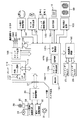
図1には、本発明の第1実施形態であるフラッシュブラケッティング機能を備えた一眼レフレックスカメラの電気的構成を示している。この図において、100はカメラ本体に内蔵された制御手段であるマイクロコンピュータの中央処理装置(以下、MPUと記す)である。このMPU100の動作周波数は、発振回路101で作られた源発振回路をMPU100内の信号により、分周しない、1/2に分周する、1/16に分周するなどして決められる。
【0014】
100bは記憶手段であるEEPROMであり、フィルムカウンタ、FEロック情報、フラッシュブラケッティング情報、その他の撮影情報を記憶可能である。100cはA/D変換器であり、後述するように焦点検出回路103、多分割測光センサ104からの入力されるアナログ信号をA/D変換する。
【0015】
MPU100には、液晶表示回路102,焦点検出回路103,測光回路104,シャッター制御回路105,モータ制御回路106,フィルム走行検知回路107,及びスイッチセンス回路108が接続されている。また、撮影レンズ1内に配置されたレンズ制御回路39とは、図2で示すマウント接点37を介して信号伝達可能に接続されている。更に、外部フラッシュ回路110とは、外部フラッシュ接点111を介して情報伝達可能に接続されている。
【0016】
液晶駆動回路102は、ファインダ視野内の焦点検出領域表示用液晶パネルであるファインダ内LCD15とファインダ視野外のファインダ内LCD20の表示をMPU100からの信号に従って制御する。
【0017】
焦点検出回路103は、MPU100の信号に従い、焦点検出用エリアセンサ6fの蓄積制御と読み出し制御を行って、それぞれの画素情報をMPU100に出力する。MPU100はこの情報をA/D変換し、周知の位相差検出法による焦点検出を行い、検出した焦点検出情報をレンズ制御回路39へ送出してレンズの焦点調節を行わせる。
【0018】
測光回路104は、画面内の各エリアの輝度信号として、測光センサ10からの出力をMPU100に出力する。MPU100は輝度信号をA/D変換し、撮影の露出の調整を行う。また、本実施形態のフラッシュ制御は、撮影時のフラッシュ発光直前にプリ発光を行い、撮影時のフラッシュ発光量を決めてしまう方式を採用しており、測光センサ10によりプリ発光時の測光も行っている。
【0019】
シャッター制御回路105は、MPU100からの信号に従って、マグネットMG−1に通電することによりシャッター先幕を走行させるとともに、マグネットMG−2に通電することによりシャッター後幕を走行させ、露出制御を行う。モータ制御回路106は、MPU100からの信号に従ってモータMを制御することにより、主ミラー2のアップダウン及びシャッターのチャージ、さらにはフィルムの給送制御を行う。
【0020】
フィルム走行検知回路107は、フィルム給送時にフィルムが1駒分巻き上げられたかを検知し、MPU100に信号を送る。
【0021】
SW1は不図示のレリーズボタンの第1ストローク操作(半押し操作)によりONし、測光,AF,動作を開始させるためのスイッチである。SW2はレリーズボタンの第2ストローク操作(全押し操作)でONし、露光動作を開始させるためのスイッチである。
【0022】
連続撮影モード(連写モード)SWは、撮影シーケンスのモードを設定するスイッチであり、連続撮影モードSWがONで連写モードが、OFFで単撮影モード(単写モード)が設定される。 その他不図示のカメラの操作部材の状態を示す信号は、スイッチセンス回路108が検知してMPU100に送られる。
【0023】
また、外部フラッシュ回路110には、フラッシュブラケッティング撮影モードを設定するためのフラッシュブラケッティングモードSWが有り、このスイッチの信号は通信によりMPU100に送られる。
【0024】
図2には、上記一眼レフレックスカメラの光学配置を示している。なお、図1と同一のものは同符号を付している。この図において、1は撮影レンズである。本図では便宜上2枚のレンズ1a、1bで示したが、実際は多数のレンズから構成されている。
【0025】
2は主ミラーであり、観察状態と撮影状態に応じて撮影光路に対して斜設又は退去される。3はサブミラーであり、撮影光路に対して斜設された主ミラー2を透過した光束をカメラボディの下方へ向けて反射する。4はシャッターである。5は感光部材であり、銀塩フィルム、CCD、MOS型等の固体撮像素子、あるいはビディコン等の撮像管により構成される。
【0026】
6は焦点検出装置であり、結像面近傍に配置されたフィールドレンズ6a、反射ミラー6b,6c、2次結像レンズ6d、絞り6e及び複数のCCD等から成るエリアセンサ6f等から構成されて、周知の位相差方式により焦点検出を行う。
【0027】
7は撮影レンズ1の予定結像面に配置されたピント板、8はファインダ光路変更用のペンタプリズムである。9、10は観察画面内の被写体輝度を測定するための結像レンズと測光センサである。結像レンズ9はペンタプリズム8内の反射光路を介して、ピント板7と測光センサ10とを共役に関係付けている。
【0028】
撮影レンズ1に取り入れられた被写体からの光(ファインダー光X1,X2)は、主ミラー2を介してピント板7上に結像し、ピント板7上の像はペンタプリズム8を介して接眼レンズ11(X1)および結像レンズ9(X2)に導かれる。これとともに表示用光X3がハーフミラー12によってファインダー光X1に合成され、これらの合成像が接眼レンズ11を介して観察者の瞳孔18に達し観察される。
【0029】
ここで、表示用光X3について説明する。まずバックライトLED17から発せられた光はフレネルレンズ16に入射し、このフレネルレンズ16によって集光されて、複数の焦点検出領域に対応した表示セグメントが形成されている焦点検出領域表示用液晶パネル15に入射する。焦点検出領域表示用液晶パネル15を透過した光束はミラー14で反射し、投影レンズ13によって集光された後、ハーフミラー12によってファインダー光X1と合成されて接眼レンズ11に導かれる。
【0030】
21はファインダ視野マスクである。また、20はファインダ視野外に撮影情報を表示するためのファインダ内LCDで、図2の照明用LED19(F−LED)によって照明されている。ファインダ内LCD20を通過した光は三角プリズム22によってファインダー内に導かれ、観察者に上記撮影情報を観察可能とする。
【0031】
31は撮影レンズ1内に設けた絞り、32は絞り駆動回路、33はレンズ駆動用モータ、34は駆動ギヤ等から成るレンズ駆動部材である。また、35はフォトカプラであり、レンズ駆動部材34に連動するパルス板36の回転を検知してレンズ焦点調節回路38に伝える。38はレンズ焦点調節回路で、フォトカプラ35からの情報とレンズ制御回路39からのレンズ駆動量の情報に基づいてレンズ駆動用モータ33を所定量駆動させ、撮影レンズ1の合焦レンズ1aを合焦位置に移動させる。レンズ制御回路39は、カメラからの情報に基づいてレンズ焦点調節回路38と絞り駆動回路32の制御を行う。
【0032】
次に、図3〜図5に示すフローチャートを用いて、本実施形態の一眼レフカメラの動作について説明する。なお、本カメラ動作は、請求項1および3に記載の発明に対応するものである。
【0033】
図3において、カメラの動作が開始すると、MPU100は、まずステップ#001にて、MPU内部の初期化を行う。次に、ステップ#002では、フラッシュブラケッティング情報等の撮影データをMPU100の内部にあるEEPROMから読み出す。
【0034】
次にステップ#003において、スイッチセンス回路108と通信を行い、スイッチ状態の検出を行う。
【0035】
次に、ステップ#004において、外部フラッシュが装着されていれているか否かを判別し、装着されているときはステップ#005へ移行し、装着されていなければステップ#010へ移行する。
【0036】
ステップ#005では、外部フラッシュと通信を行い、フラッシュブラケッティングモードの設定情報、充電状態情報等の外部フラッシュ情報を得る。
【0037】
次にステップ#006において、フラッシュブラケッティング撮影モードが設定されているときはステップ#007へ移行し、フラッシュブラケッティング撮影モードが設定されていなければステップ#010へ移行する。
【0038】
ステップ#007では、フラッシュの充電電圧が発光可能電圧より低いか否か(充電完了していないか否か)を判別し、充電完了していないときはステップ#011へ移行し、充電完了しているときはステップ#008へ移行する。
【0039】
ステップ#008では、フラッシュブラケッティング撮影モードにおける撮影シーン数を示すフラグであるFEB_COUNTが≠0か否かを判別し、≠0のときはステップ#010へ移行し、0のときはステップ#009に移行する。
【0040】
ステップ#009では、フラッシュブラケッティングモードにおける1シーン目の撮影であることを示すためにFEB_COUNTに1を設定し、ステップ#011へ移行する。
ステップ#010では、外部フラッシュが装着されていないので、フラッシュ関係の情報をクリアする。なお、このステップ以降は、FEB_COUNT=0のときは、フラッシュブラケッティング撮影モードでないと判断できる。
【0041】
ステップ#011では、スイッチSW1がオフか否かを判別し、オフのときはステップ#019(EEPROM書き込みステップ)へ進み、撮影情報をEEPROMに書き込んでプログラムを終了する。一方、SW1がオンのときはステップ#012へ移行して、撮影準備動作に入る。
【0042】
ステップ#012では、測光回路104からの被写体の輝度情報に基づいてシャッタースピードとレンズの絞り値を演算により算出して露出量を決定する。
【0043】
次に、ステップ#013において焦点検出動作を行う。これは、前述したように焦点検出回路103によって位相差検出法により行われる。
【0044】
さらに、ステップ#014において、MPU100は、上記焦点検出動作により得られた焦点検出状態によりレンズ制御回路39を制御することによって、レンズの焦点調節を行う。そして、次のステップ#015において、ステップ#012により得られたシャッタースピード、絞り値及びステップ#013により得られた焦点検出結果をファインダー内に表示するため、液晶表示回路102と通信を行う。
【0045】
続くステップ#016では、スイッチSW2の状態を調べ、オフであればステップ#018へ移行し、オンであればステップ#017へ移行してフィルムに露光させるためのレリーズ制御を行う。
【0046】
ここで、図4に示すフローチャートによりレリーズ制御を詳細に説明する。レリーズ制御に入ると、まずステップ#201で、外部フラッシュが装着されているか否かを判別し、装着されているときはステップ#202へ移行し、装着されていないときはステップ#206へ移行する。
【0047】
ステップ#202では、充電完了していないか否かを判別し、充電完了していなければステップ#203へ移行し、充電完了しているときはステップ#204へ移行する。
【0048】
ステップ#203では、フラッシュブラケッティング撮影モードが設定されているか否かを判別し、同モードが設定されているときはリターンして、レリーズ動作(撮影動作)を行わずに、つまりはレリーズ動作を禁止して、図3のステップ#108に戻る。一方、フラッシュブラケッティング撮影モードが設定されていないときは、ステップ#206へ移行してレリーズ動作を開始する。
【0049】
また、ステップ#204では、外部フラッシュのプリ発光制御を行い、測光回路104の出力より被写体に当たったプリ発光量ΔFを算出する。更に、フラッシュとの通信によりこの時のプリ発光量を受信し、PRE_LEVELとして記憶する。
【0050】
そして、ステップ#205において、フラッシュ発光量の演算を行う。ここで、図5に示すフローチャートにより、発光量演算の詳細な説明を行う。
【0051】
まず、ステップ#301では、FEB_COUNTが0又は1か否かを判別し、0又は1のときはステップ#302に進み、F_COMP(調光補正量)=20 とし、0又は1以外のときは、ステップ#303へ移行する。
【0052】
ステップ#303では、FEB_COUNTが2か否かを判別し、2のときはステップ#304へ移行して、F_COMP=2-1とし、2より大きいときは、ステップ#305へ移行して、F_COMP=21 とする。すなわち、フラッシュブラケッティングモードでないか又はフラッシュブラケッティング撮影モードの1シーケンスのうち1シーン目のときは調光補正を掛けず、フラッシュブラケッティング撮影モードの1シーケンスのうち2シーン目のときは、調光補正を−1段掛け、フラッシュブラケッティング撮影モードの1シーケンスのうち3シーン目以降のときは、調光補正を+1段掛ける。
【0053】
そして、ステップ#306において、フラッシュのメイン発光量F_OUTを演算し、リターンする。
【0054】
F_OUT=F_COMP×(PRE_LEVEL×EVt÷ΔF)
但し、F_COMP:調光補正量
PRE_LEVEL:フラッシュプリ発光量
EVt:目的の露光量
ΔF:被写体に当たるプリ発光量
なお、本実施形態では、フラッシュ露光量演算や測光演算などをアスペック値で演算する。
【0055】
図4のフローに戻り、ステップ#206では、モータ制御回路106を介してモータMを駆動し、主ミラー2をアップさせる。
【0056】
次にステップ#207において、レンズ制御回路39に絞り値を送り、レンズを指定値に絞り込む。
【0057】
さらに、ステップ#208では、フラッシュ撮影か否かを判別し、フラッシュ撮影ならばステップ#209にて外部フラッシュと通信を行い、フラッシュ発光量及び発光開始を送信する。フラッシュ撮影でなければ、ステップ#210に移行して、シャッター制御回路105により先幕を走らせる。
【0058】
そして、ステップ#211において、設定した露出時間が経過したか否かを判別し、経過していなければループして、経過するまで待つ。
【0059】
設定露出時間が経過したときは、ステップ#212に進み、シャッター制御回路105により後幕を走らせる。
【0060】
次に、ステップ#213において、レンズ制御回路39と通信を行い、絞りを開放にする。
【0061】
次に、ステップ#214において、モータ制御回路106を介してモータMを駆動し、主ミラー2をダウンさせる。
【0062】
次に、ステップ#215において、フラッシュ撮影されたか否かを判別し、フラッシュ撮影されたときはステップ#216へ移行し、非フラッシュ撮影されたときはステップ#220へ移行する。
【0063】
ステップ#216では、FEB_COUNT>0か否かを判別し、FEB_COUNT>0のときはステップ#217へ移行し、そうでなければステップ#220へ移行する。
【0064】
ステップ#217では、FEB_COUNT=FEB_COUNT+1の演算を行い、フラッシュブラケッティングの撮影シーンカウントを1つアップさせる。
【0065】
そして、ステップ#218において、FEB_COUNT>3か否かを判別し、FEB_COUNT>3のときは、ステップ#219に進んでFEB_COUNT=0とし、そうでなければステップ#220へ移行する。すなわち、FEB_COUNTの値は、0〜3までとし、フラッシュブラケッティングは3回の撮影を1シーケンスとする。
【0066】
こうしてフィルム1駒の露光が終了し、ステップ#220でフィルムが装填されていると判別されると、ステップ#221に進んでフィルムを1駒分給送し、ステップ#222へ移行する。フィルムが装填されていないときは、そのままステップ#222へ移行する。
【0067】
ステップ#222では、連写モードが設定されていないか否かを判別し、連写モードが設定されていないときはステップ#223に進んで、スイッチ情報を読み込み、ステップ224へ移行する。一方、連写モードが設定されているときはリターンする。
【0068】
ステップ#224では、レリーズ操作スイッチであるSW2がオンか否かを判別し、オンのときはステップ#223へループし、オフのときはリターンする。以上のようにしてレリーズ制御を終了すると、図3のフローに戻り、ステップ#018において、スイッチSW1がオンか否かを判別する。オンのときはステップ#003に戻り、オフのときはステップ#019に進んで、フラッシュブラケッティング情報等の各種撮影情報をEEPROMに記憶し、プログラムを終了する。
【0069】
(第2実施形態)
次に、本発明の第2実施形態であるカメラのレリーズ制御を図6のフローチャートを用いて説明する。なお、本実施形態は、請求項2に記載の発明に対応するものであり、レリーズ制御以外のカメラ制御については第1実施形態と同じである。
【0070】
レリーズ制御に入ると、まずステップ#201で、外部フラッシュが装着されているか否かを判別し、装着されているときはステップ#202へ移行し、装着されていないときはステップ#206へ移行する。
【0071】
ステップ#202では、充電完了していないか否かを判別し、充電完了していなければステップ#203へ移行し、充電完了しているときはステップ#204へ移行する。
【0072】
ステップ#203では、FEB_COUNT>1か否かを判別し、FEB_COUNT>1のとき(1シーン以上撮影した後であるとき)はレリーズ動作(撮影動作)を行わずに、つまりはレリーズ動作を禁止して、図3のステップ#018に戻る。一方、FEB_COUNT=0のとき(まだ1シーンも撮影していないとき)は、ステップ#206へ移行してレリーズ動作を開始する。
【0073】
また、ステップ#204では、外部フラッシュのプリ発光制御を行い、測光回路104の出力より被写体に当たったプリ発光量ΔFを算出する。更に、フラッシュとの通信によりこの時のプリ発光量を受信し、PRE_LEVELとして記憶する。
【0074】
そして、ステップ#205において、第1実施形態の図5に示したフローチャートに従ってフラッシュ発光量の演算を行い、ステップ#206に移行する。
【0075】
ステップ#206では、モータ制御回路106を介してモータMを駆動し、主ミラー2をアップさせる。
【0076】
次にステップ#207において、レンズ制御回路39に絞り値を送り、レンズを指定値に絞り込む。
【0077】
さらに、ステップ#208では、フラッシュ撮影か否かを判別し、フラッシュ撮影ならばステップ#209にて外部フラッシュと通信を行い、フラッシュ発光量及び発光開始を送信する。フラッシュ撮影でなければ、ステップ#210に移行して、シャッター制御回路105により先幕を走らせる。
【0078】
そして、ステップ#211において、設定した露出時間が経過したか否かを判別し、経過していなければループして、経過するまで待つ。
【0079】
設定露出時間が経過したときは、ステップ#212に進み、シャッター制御回路105により後幕を走らせる。
【0080】
次に、ステップ#213において、レンズ制御回路39と通信を行い、絞りを開放にする。
【0081】
次に、ステップ#214において、モータ制御回路106を介してモータMを駆動し、主ミラー2をダウンさせる。
【0082】
次に、ステップ#215において、フラッシュ撮影されたか否かを判別し、フラッシュ撮影されたときはステップ#216へ移行し、非フラッシュ撮影されたときはステップ#220へ移行する。
【0083】
ステップ#216では、FEB_COUNT>0か否かを判別し、FEB_COUNT>0のときはステップ#217へ移行し、そうでなければステップ#220へ移行する。
【0084】
ステップ#217では、FEB_COUNT=FEB_COUNT+1の演算を行い、フラッシュブラケッティングの撮影シーンカウントを1つアップさせる。
【0085】
そして、ステップ#218において、FEB_COUNT>3か否かを判別し、FEB_COUNT>3のときは、ステップ#219に進んでFEB_COUNT=0とし、そうでなければステップ#220へ移行する。すなわち、FEB_COUNTの値は、0〜3までとし、フラッシュブラケッティングは3回の撮影を1シーケンスとする。
【0086】
こうしてフィルム1駒の露光が終了し、ステップ#220でフィルムが装填されていると判別されると、ステップ#221に進んでフィルムを1駒分給送し、ステップ#222へ移行する。フィルムが装填されていないときは、そのままステップ#222へ移行する。
【0087】
ステップ#222では、連写モードが設定されていないか否かを判別し、連写モードが設定されていないときはステップ#223に進んで、スイッチ情報を読み込み、ステップ224へ移行する。一方、連写モードが設定されているときはリターンする。
【0088】
ステップ#224では、レリーズ操作スイッチであるSW2がオンか否かを判別し、オンのときはステップ#223へループし、オフのときはリターンする。(第3実施形態)
次に、本発明の第3実施形態であるカメラのレリーズ制御を図7のフローチャートを用いて説明する。なお、本実施形態は、請求項4,6,8に記載の発明に対応するものであり、レリーズ制御以外のカメラ制御については第1実施形態と同じである。
【0089】
レリーズ制御に入ると、まずステップ#201で、外部フラッシュが装着されているか否かを判別し、装着されているときはステップ#202へ移行し、装着されていないときはステップ#206へ移行する。
【0090】
ステップ#202では、充電完了していないか否かを判別し、充電完了していなければステップ#206へ移行してレリーズ動作を開始し、充電完了しているときはステップ#204へ移行する。
【0091】
ステップ#204では、外部フラッシュのプリ発光制御を行い、測光回路104の出力より被写体に当たったプリ発光量ΔFを算出する。更に、フラッシュとの通信によりこの時のプリ発光量を受信し、PRE_LEVELとして記憶する。
【0092】
そして、ステップ#205において、第1実施形態の図5に示したフローチャートに従ってフラッシュ発光量の演算を行い、ステップ#206に移行する。
【0093】
ステップ#206では、モータ制御回路106を介してモータMを駆動し、主ミラー2をアップさせる。
【0094】
次にステップ#207において、レンズ制御回路39に絞り値を送り、レンズを指定値に絞り込む。
【0095】
さらに、ステップ#208では、フラッシュ撮影か否かを判別し、フラッシュ撮影ならばステップ#209にて外部フラッシュと通信を行い、フラッシュ発光量及び発光開始を送信する。フラッシュ撮影でなければ、ステップ#210に移行して、シャッター制御回路105により先幕を走らせる。
【0096】
そして、ステップ#211において、設定した露出時間が経過したか否かを判別し、経過していなければループして、経過するまで待つ。
【0097】
設定露出時間が経過したときは、ステップ#212に進み、シャッター制御回路105により後幕を走らせる。
【0098】
次に、ステップ#213において、レンズ制御回路39と通信を行い、絞りを開放にする。
【0099】
次に、ステップ#214において、モータ制御回路106を介してモータMを駆動し、主ミラー2をダウンさせる。
【0100】
次に、ステップ#215において、フラッシュ撮影されたか否かを判別し、フラッシュ撮影されたときはステップ#216へ移行し、非フラッシュ撮影されたときはステップ#220へ移行する。
【0101】
ステップ#216では、FEB_COUNT>0か否かを判別し、FEB_COUNT>0のときはステップ#217へ移行し、そうでなければステップ#220へ移行する。
【0102】
ステップ#217では、FEB_COUNT=FEB_COUNT+1の演算を行い、フラッシュブラケッティングの撮影シーンカウントを1つアップさせる。
【0103】
そして、ステップ#218において、FEB_COUNT>3か否かを判別し、FEB_COUNT>3のときは、ステップ#219に進んでFEB_COUNT=0とし、そうでなければステップ#220へ移行する。すなわち、FEB_COUNTの値は、0〜3までとし、フラッシュブラケッティングは3回の撮影を1シーケンスとする。
【0104】
こうしてフィルム1駒の露光が終了し、ステップ#220でフィルムが装填されていると判別されると、ステップ#221に進んでフィルムを1駒分給送し、ステップ#222へ移行する。フィルムが装填されていないときは、そのままステップ#222へ移行する。
【0105】
ステップ#222では、連写モードが設定されていないか否かを判別し、連写モードが設定されていないときはステップ#223に進んで、スイッチ情報を読み込み、ステップ224へ移行する。ステップ#224では、レリーズ操作スイッチであるSW2がオンか否かを判別し、オンのときはステップ#223へループし、オフのときはステップ#225に進む。一方、ステップ#223にて連写モードが設定されているときはそのままステップ#225に進む。
【0106】
ステップ#225では、フラッシュブラケッティング撮影モードが設定されているか否かを判別し、フラッシュブラケッティング撮影モードが設定されているときはステップ#226へ移行し、そうでなければリターンする。
【0107】
ステップ#226では、撮影シーケンスが連写モードに設定されていないか否かを判別する。連写モードに設定されていないとき(単写モードが設定さけれているとき)はリターンし、連写モードに設定されているときはステップ#227に進んで、外部フラッシュと通信を行い、フラッシュの充電電圧を検知する。
【0108】
そして、ステップ#228において、フラッシュの充電電圧が発光可能電圧より低いか否かを判別する。ここで、充電電圧が発光可能電圧より低いときは、ステップ#227にループする。すなわち、レリーズ動作を禁止して、充電電圧が発光可能電圧に達するまで待つ。
【0109】
一方、充電電圧が発光可能電圧以上のとき(充電完了のとき)はリターンして、連写モードにおける次のレリーズ動作を許容する。
【0110】
このように、本実施形態では、ステップ#225から#228により、フラッシュブラケッティング撮影モードにて連写モードが設定されている場合に、フラッシュの充電電圧が発光可能電圧より低いときはフラッシュの充電完了待ちを行う一方、フラッシュブラケッティング撮影モードにて単写モードが設定されているときは、レリーズ制御プログラムからリターンされるので、次のレリーズ操作で、フラッシュが充電完了していなくても、非フラッシュ撮影が可能となる。
【0111】
なお、ステップ#225を、フラッシュブラケッティング撮影モードに設定されているか否かの判別に代えて、FEB_COUNT>0か否かの判別を行うようにすれば、フラッシュブラケッティング撮影モードでないときだけでなく、フラッシュブラケッティングの1シーケンス終了時も、ステップ#226〜#228を通らなくさせることが可能である。すなわち、フラッシュブラケッティング中のみレリーズ禁止の充電完了待ちを行わせることができる。
【0112】
(第4実施形態)
次に、本発明の第4実施形態であるカメラのレリーズ制御を図8のフローチャートを用いて説明する。なお、本実施形態は、請求項5,7に記載の発明に対応するものであり、レリーズ制御以外のカメラ制御については第1実施形態と同じである。
【0113】
レリーズ制御に入ると、まずステップ#201で、外部フラッシュが装着されているか否かを判別し、装着されているときはステップ#202へ移行し、装着されていないときはステップ#206へ移行する。
【0114】
ステップ#202では、充電完了していないか否かを判別し、充電完了していなければステップ#206へ移行してレリーズ動作を開始し、充電完了しているときはステップ#204へ移行する。
【0115】
ステップ#204では、外部フラッシュのプリ発光制御を行い、測光回路104の出力より被写体に当たったプリ発光量ΔFを算出する。更に、フラッシュとの通信によりこの時のプリ発光量を受信し、PRE_LEVELとして記憶する。
【0116】
そして、ステップ#205において、第1実施形態の図5に示したフローチャートに従ってフラッシュ発光量の演算を行い、ステップ#206に移行する。
【0117】
ステップ#206では、モータ制御回路106を介してモータMを駆動し、主ミラー2をアップさせる。
【0118】
次にステップ#207において、レンズ制御回路39に絞り値を送り、レンズを指定値に絞り込む。
【0119】
さらに、ステップ#208では、フラッシュ撮影か否かを判別し、フラッシュ撮影ならばステップ#209にて外部フラッシュと通信を行い、フラッシュ発光量及び発光開始を送信する。フラッシュ撮影でなければ、ステップ#210に移行して、シャッター制御回路105により先幕を走らせる。
【0120】
そして、ステップ#211において、設定した露出時間が経過したか否かを判別し、経過していなければループして、経過するまで待つ。
【0121】
設定露出時間が経過したときは、ステップ#212に進み、シャッター制御回路105により後幕を走らせる。
【0122】
次に、ステップ#213において、レンズ制御回路39と通信を行い、絞りを開放にする。
【0123】
次に、ステップ#214において、モータ制御回路106を介してモータMを駆動し、主ミラー2をダウンさせる。
【0124】
次に、ステップ#215において、フラッシュ撮影されたか否かを判別し、フラッシュ撮影されたときはステップ#216へ移行し、非フラッシュ撮影されたときはステップ#220へ移行する。
【0125】
ステップ#216では、FEB_COUNT>0か否かを判別し、FEB_COUNT>0のときはステップ#217へ移行し、そうでなければステップ#220へ移行する。
【0126】
ステップ#217では、FEB_COUNT=FEB_COUNT+1の演算を行い、フラッシュブラケッティングの撮影シーンカウントを1つアップさせる。
【0127】
そして、ステップ#218において、FEB_COUNT>3か否かを判別し、FEB_COUNT>3のときは、ステップ#219に進んでFEB_COUNT=0とし、そうでなければステップ#220へ移行する。すなわち、FEB_COUNTの値は、0〜3までとし、フラッシュブラケッティングは3回の撮影を1シーケンスとする。
【0128】
こうしてフィルム1駒の露光が終了し、ステップ#220でフィルムが装填されていると判別されると、ステップ#221に進んでフィルムを1駒分給送し、ステップ#222へ移行する。フィルムが装填されていないときは、そのままステップ#222へ移行する。
【0129】
ステップ#222では、連写モードが設定されていないか否かを判別し、連写モードが設定されていないときはステップ#223に進んで、スイッチ情報を読み込み、ステップ224へ移行する。ステップ#224では、レリーズ操作スイッチであるSW2がオンか否かを判別し、オンのときはステップ#223へループし、オフのときはステップ#225に進む。一方、ステップ#223にて連写モードが設定されているときはそのままステップ#225に進む。
【0130】
ステップ#225では、フラッシュブラケッティング撮影モードが設定されているか否かを判別し、フラッシュブラケッティング撮影モードが設定されているときはステップ#226へ移行し、そうでなければリターンする。
【0131】
ステップ#226では、撮影シーケンスが連写モードに設定されていないか否かを判別する。連写モードに設定されていないとき(単写モードが設定さけれているとき)はリターンし、連写モードに設定されているときはステップ#227に進んで、外部フラッシュと通信を行い、フラッシュの充電電圧を検知する。
【0132】
そして、ステップ#228において、フラッシュの充電電圧が発光可能電圧より低いか否かを判別する。ここで、充電電圧が発光可能電圧より低いときは、ステップ#229に進む。ステップ#229では、スイッチSW2がオンされていないか否かを判別し、オンのときはステップ#227へループし、オフならばリターンする。また、ステップ#228において、フラッシュの充電電圧が発光可能電圧以上のとき(充電完了のとき)はリターンして、連写モードにおける次のレリーズ動作を許容する。
【0133】
このように本実施形態によれば、ステップ#225から#229により、フラッシュブラケッティング撮影モードにて連写モードが設定されている場合に、フラッシュの充電電圧が発光可能電圧より低いときはフラッシュの充電完了待ちを行うが、充完待ちをしている間にスイッチSW2をオフにすれば(レリーズ操作をやめれば)、充電完了待ちを中止してリターンするので、次のレリーズ操作でフラッシュが充電完了していなくても、非フラッシュ撮影が可能となる。
【0134】
なお、ステップ#225を、フラッシュブラケッティング撮影モードに設定されているか否かの判別に代えて、FEB_COUNT>0か否かの判別を行うようにすれば、フラッシュブラケッティング撮影モードでないときだけでなく、フラッシュブラケッティングの1シーケンス終了時も、ステップ#226〜#228を通らなくさせることが可能である。すなわち、フラッシュブラケッティング中のみレリーズ禁止の充電完了待ちを行わせることができる。
【0135】
【発明の効果】
以上説明したように、本発明によれば、フラッシュブラケッティング撮影モード設定状態においてフラッシュ充電電圧が発光可能電圧より低下している間は撮影動作自体が禁止されるため、従来のカメラのようにフラッシュブラケッティング撮影中に非フラッシュ撮影が行われてしまうことを防止でき、フラッシュブラケッティングの1シーケンス中のフラッシュ露光量の連続性を保つことができる。また、撮影動作が禁止されている状態でも、レリーズ操作を解除した後に再度レリーズ操作を行うことにより非フラッシュ撮影が許容されるようにすれば、上記撮影動作の禁止によりシャッターチャンスを逃す恐れをなくすことができる。
【0136】
なお、フラッシュブラケッティング撮影モードでも連続撮影を行うのでなければ、フラッシュ充電電圧が発光可能電圧より低くても非フラッシュ撮影動作が許容され、上記撮影動作の禁止によりシャッターチャンスを逃す恐れをなくすことができる。
【図面の簡単な説明】
【図1】本発明の第1実施形態である一眼レフレックスカメラに内蔵された電気的構成の要部を示すブロック図である。
【図2】上記一眼レフレックスカメラの光学配置を示す図である。
【図3】上記カメラの一連の動作の制御フローチャートである。
【図4】上記カメラのレリーズ動作の制御フローチャートである。
【図5】上記カメラにおけるフラッシュ発光量の演算フローチャートである。
【図6】本発明の第2実施形態であるカメラのレリーズ動作の制御フローチャートである。
【図7】本発明の第3実施形態であるカメラのレリーズ動作の制御フローチャートである。
【図8】本発明の第4実施形態であるカメラのレリーズ動作の制御フローチャートである。
【符号の説明】
100 MPU
FEB_COUNT フラッシュブラケッティング撮影シーンカウント用フラグ
F_OUT フラッシュ(メイン)発光量
F_COMP 調光補正量[0001]
BACKGROUND OF THE INVENTION
The present invention relates to a camera having a so-called flash bracketing function.
[0002]
[Prior art]
The flash bracketing function is a function capable of increasing / decreasing the flash emission amount by an arbitrary amount with respect to a predetermined value (appropriate value) for each flash photography. Conventionally, in cameras with this function, if the flash charging voltage drops below the flashable voltage during flash bracketing shooting, shooting with only external light without using the flash when a release operation is performed ( (Non-flash shooting).
[0003]
[Problems to be solved by the invention]
However, when non-flash shooting is performed during flash bracketing shooting in this way, the continuity of the flash exposure amount is lost during one flash bracketing sequence (for example, three shots are set as one sequence). There is a problem.
[0004]
Accordingly, the present invention provides a camera capable of maintaining the continuity of the flash exposure amount in one flash bracketing sequence even when the flash charging voltage is lower than the light emission possible voltage during flash bracketing photography. The purpose is to provide.
[0005]
Another object of the present invention is to provide a camera capable of avoiding missing a photo opportunity while achieving the above object.
[0008]
The present inventionIn each flash shooting, the flash output isIncrease or decreaseThe flash bracketing shooting mode can be setTo start the exposure operationIn a camera capable of continuous shooting according to the release operation, in flash bracketing shooting modethe aboveAfter a release operation has been performed and at least one scene of flash photography has been performedthe aboveWhen the release operation continues, the flash charge voltage is higher than the flashable voltage.If the flash charging voltage is high, the flash shooting operation is allowed. If the flash charging voltage is lower than the flashable voltage, the flash charge voltage reaches the flashable voltage.Provide control means to prohibit shootingThe control means prohibits the photographing operation, and when the release operation is performed again after the release operation is released, the flash charging voltage is lower than the light emission possible voltage. Allow shooting operation without flash.
[0010]
BookAccording to the present invention, since the shooting operation itself is prohibited while the flash charging voltage is lowered below the light emission enable voltage such as the light emission prohibition voltage during flash bracketing shooting, the flash bracketing is performed like a conventional camera. It is possible to prevent photographing without using a flash during photographing, and it is possible to maintain the continuity of the flash exposure amount in one flash bracketing sequence.
[0011]
Also,Prohibit shooting operationIn the state,the aboveRelease operation is canceledThen release operation is performed again.IfIsWhen the flash charging voltage is lower than the flashable voltageIn addition,Permits shooting without using a flashBecause, So as not to miss the shutter chanceis doing.
[0012]
Also,In a camera capable of selectively setting a continuous shooting mode in which continuous shooting is performed in accordance with the release operation and a single shooting mode in which the shooting operation is terminated for each frame shooting in accordance with the release operation,When the single shooting mode is set in the flash bracketing shooting mode, the flash charging voltage is lower than the flashable voltage.If the conditionIt is desirable to allow the control means to perform a photographing operation without using a flash so as not to miss a photo opportunity.
[0013]
DETAILED DESCRIPTION OF THE INVENTION
(First embodiment)
FIG. 1 shows an electrical configuration of a single-lens reflex camera having a flash bracketing function according to the first embodiment of the present invention. In this figure,
[0014]
[0015]
A liquid
[0016]
The liquid
[0017]
The
[0018]
The
[0019]
In accordance with a signal from the MPU 100, the
[0020]
The film running
[0021]
SW1 is a switch for turning on by a first stroke operation (half-pressing operation) of a release button (not shown) to start photometry, AF, and operation. SW2 is a switch that is turned on by the second stroke operation (full pressing operation) of the release button and starts an exposure operation.
[0022]
The continuous shooting mode (continuous shooting mode) SW is a switch for setting the mode of the shooting sequence. The continuous shooting mode SW is set to ON, the continuous shooting mode is set to OFF, and the single shooting mode (single shooting mode) is set to OFF. Other signals indicating the state of the operation member of the camera (not shown) are detected by the
[0023]
The
[0024]
FIG. 2 shows an optical arrangement of the single-lens reflex camera. In addition, the same thing as FIG. 1 is attached | subjected the same code | symbol. In this figure, 1 is a taking lens. In this figure, the two
[0025]
[0026]
[0027]
Reference numeral 7 denotes a focusing plate disposed on the planned imaging plane of the taking
[0028]
Light from the subject (finder light X1, X2) taken into the photographing
[0029]
Here, the display light X3 will be described. First, the light emitted from the
[0030]
[0031]
[0032]
Next, the operation of the single-lens reflex camera of this embodiment will be described using the flowcharts shown in FIGS. This camera operation corresponds to the inventions described in
[0033]
In FIG. 3, when the operation of the camera starts, the
[0034]
Next, in
[0035]
Next, in
[0036]
In
[0037]
Next, at
[0038]
In
[0039]
In
[0040]
In
In
[0041]
In
[0042]
In
[0043]
Next, a focus detection operation is performed in
[0044]
In
[0045]
In the
[0046]
Here, the release control will be described in detail with reference to the flowchart shown in FIG. When the release control is entered, first, in
[0047]
In
[0048]
In
[0049]
In
[0050]
In
[0051]
First, in
[0052]
In
[0053]
In step # 306, the main flash emission amount F_OUT is calculated and the process returns.
[0054]
F_OUT = F_COMP × (PRE_LEVEL × EVt ÷ ΔF)
However, F_COMP: Dimming correction amount
PRE_LEVEL: Flash pre-emission amount
EVt: Target exposure amount
ΔF: Pre-flash amount hitting the subject
In the present embodiment, the flash exposure amount calculation, the photometry calculation, and the like are calculated using the Aspec value.
[0055]
Returning to the flow of FIG. 4, in
[0056]
Next, in
[0057]
Further, in
[0058]
In
[0059]
When the set exposure time has elapsed, the process proceeds to step # 212 where the
[0060]
Next, in
[0061]
Next, in
[0062]
Next, in
[0063]
In
[0064]
In
[0065]
In
[0066]
When the exposure of one frame of film is completed in this way and it is determined in
[0067]
In
[0068]
In
[0069]
(Second Embodiment)
Next, the release control of the camera according to the second embodiment of the present invention will be described with reference to the flowchart of FIG. The present embodiment corresponds to the invention described in
[0070]
When the release control is entered, first, in
[0071]
In
[0072]
In
[0073]
In
[0074]
In
[0075]
In
[0076]
Next, in
[0077]
Further, in
[0078]
In
[0079]
When the set exposure time has elapsed, the process proceeds to step # 212 where the
[0080]
Next, in
[0081]
Next, in
[0082]
Next, in
[0083]
In
[0084]
In
[0085]
In
[0086]
When the exposure of one frame of film is completed in this way and it is determined in
[0087]
In
[0088]
In
Next, the release control of the camera according to the third embodiment of the present invention will be described with reference to the flowchart of FIG. This embodiment corresponds to the invention described in
[0089]
When the release control is entered, first, in
[0090]
In
[0091]
In
[0092]
In
[0093]
In
[0094]
Next, in
[0095]
Further, in
[0096]
In
[0097]
When the set exposure time has elapsed, the process proceeds to step # 212 where the
[0098]
Next, in
[0099]
Next, in
[0100]
Next, in
[0101]
In
[0102]
In
[0103]
In
[0104]
When the exposure of one frame of film is completed in this way and it is determined in
[0105]
In
[0106]
In
[0107]
In
[0108]
Then, in
[0109]
On the other hand, when the charging voltage is equal to or higher than the light emission possible voltage (when charging is completed), the process returns to allow the next release operation in the continuous shooting mode.
[0110]
As described above, in the present embodiment, when the continuous shooting mode is set in the flash bracketing shooting mode in steps # 225 to # 228, the flash charging is performed when the flash charging voltage is lower than the flashable voltage. While waiting for completion, when the single shooting mode is set in the flash bracketing shooting mode, the release control program returns, so even if the flash is not fully charged in the next release operation, Flash photography is possible.
[0111]
Note that if
[0112]
(Fourth embodiment)
Next, the release control of the camera according to the fourth embodiment of the present invention will be described with reference to the flowchart of FIG. The present embodiment corresponds to the inventions described in claims 5 and 7, and camera control other than the release control is the same as that of the first embodiment.
[0113]
When the release control is entered, first, in
[0114]
In
[0115]
In
[0116]
In
[0117]
In
[0118]
Next, in
[0119]
Further, in
[0120]
In
[0121]
When the set exposure time has elapsed, the process proceeds to step # 212 where the
[0122]
Next, in
[0123]
Next, in
[0124]
Next, in
[0125]
In
[0126]
In
[0127]
In
[0128]
When the exposure of one frame of film is completed in this way and it is determined in
[0129]
In
[0130]
In
[0131]
In
[0132]
Then, in
[0133]
As described above, according to the present embodiment, when the continuous shooting mode is set in the flash bracketing shooting mode in steps # 225 to # 229, when the flash charging voltage is lower than the flashable voltage, the flash Waiting for charging completion, but if switch SW2 is turned off while waiting for charging (if the release operation is stopped), the charging completion wait is canceled and the process returns, so the flash is charged in the next release operation. Even if it is not completed, non-flash photography is possible.
[0134]
Note that if
[0135]
【The invention's effect】
As explained above,The present inventionAccording to the above, since the shooting operation itself is prohibited while the flash charging voltage is lower than the flashable voltage in the flash bracketing shooting mode setting state, the non-flash shooting is performed during flash bracketing shooting like a conventional camera. Can be prevented, and the continuity of the flash exposure amount in one flash bracketing sequence can be maintained.Even if the shooting operation is prohibited, if the non-flash shooting is allowed by performing the release operation again after releasing the release operation, the possibility of missing a photo opportunity due to the prohibition of the shooting operation is eliminated. be able to.
[0136]
Unless continuous shooting is performed even in flash bracketing shooting mode, non-flash shooting is allowed even if the flash charging voltage is lower than the flashable voltage.,There is a risk of missing a photo opportunity by prohibiting the above shooting operationsTo loseCan do.
[Brief description of the drawings]
FIG. 1 is a block diagram showing a main part of an electrical configuration built in a single-lens reflex camera according to a first embodiment of the present invention.
FIG. 2 is a diagram illustrating an optical arrangement of the single-lens reflex camera.
FIG. 3 is a control flowchart of a series of operations of the camera.
FIG. 4 is a control flowchart of the release operation of the camera.
FIG. 5 is a calculation flowchart of flash light emission amount in the camera.
FIG. 6 is a control flowchart of the release operation of the camera according to the second embodiment of the present invention.
FIG. 7 is a control flowchart of a release operation of the camera according to the third embodiment of the present invention.
FIG. 8 is a control flowchart of a release operation of the camera according to the fourth embodiment of the present invention.
[Explanation of symbols]
100 MPU
FEB_COUNT Flash bracketing shooting scene counting flag
F_OUT Flash (main) flash output
F_COMP Dimming correction amount
Claims (2)
前記フラッシュブラケッティング撮影モードにて前記レリーズ操作が行われ、少なくとも1シーンのフラッシュ撮影動作が行われた後に前記レリーズ操作が引き続き行われている場合に、フラッシュ充電電圧が発光可能電圧より高い状態であればフラッシュ撮影動作を許容し、前記フラッシュ充電電圧が前記発光可能電圧より低い状態であれば前記フラッシュ充電電圧が前記発光可能電圧に達するまで撮影動作を禁止する制御手段を有し、
前記制御手段は、前記撮影動作を禁止している場合であって、前記レリーズ操作が解除されてから前記レリーズ操作が再度行われた場合には、前記フラッシュ充電電圧が前記発光可能電圧より低い状態であればフラッシュを使わない撮影動作を許容することを特徴とするカメラ。In a camera that can set a flash bracketing shooting mode that increases or decreases the flash emission amount with respect to a predetermined value for each flash shooting, and can perform continuous shooting according to a release operation for starting an exposure operation ,
Wherein the release operation by flash bracketing photographing mode is performed, when the release operation after the flash photographing operation of at least one scene has been performed is continue to be made, in a state higher than the emission can voltage flash charge voltage if permit flash photography operation, have a control means that the flash charge voltage if the flash charge voltage is lower than that the light emitting voltage prohibits the photographing operation to reach the emission possible voltage,
When the control unit prohibits the photographing operation and the release operation is performed again after the release operation is released, the flash charging voltage is lower than the light emission possible voltage. If so, a camera that allows shooting without using a flash .
前記制御手段は、前記フラッシュブラケッティング撮影モードにて前記単撮影モードが設定されている場合において、前記フラッシュ充電電圧が前記発光可能電圧より低い状態であればフラッシュを使わない撮影動作を許容することを特徴とする請求項1に記載のカメラ。 A camera capable of selectively setting a continuous shooting mode in which continuous shooting is performed in accordance with the release operation and a single shooting mode in which a shooting operation is terminated for each frame shooting in accordance with the release operation;
Said control means permitting the In no event the single shooting mode is set, the flash charging voltage without the flash if lower than the light emitting Voltage photographing operation in the flash bracketing photographing mode The camera according to claim 1, wherein:
Priority Applications (2)
| Application Number | Priority Date | Filing Date | Title |
|---|---|---|---|
| JP08674798A JP3907308B2 (en) | 1998-03-31 | 1998-03-31 | camera |
| US09/273,376 US6047137A (en) | 1998-03-31 | 1999-03-22 | Camera |
Applications Claiming Priority (1)
| Application Number | Priority Date | Filing Date | Title |
|---|---|---|---|
| JP08674798A JP3907308B2 (en) | 1998-03-31 | 1998-03-31 | camera |
Publications (2)
| Publication Number | Publication Date |
|---|---|
| JPH11282064A JPH11282064A (en) | 1999-10-15 |
| JP3907308B2 true JP3907308B2 (en) | 2007-04-18 |
Family
ID=13895381
Family Applications (1)
| Application Number | Title | Priority Date | Filing Date |
|---|---|---|---|
| JP08674798A Expired - Fee Related JP3907308B2 (en) | 1998-03-31 | 1998-03-31 | camera |
Country Status (1)
| Country | Link |
|---|---|
| JP (1) | JP3907308B2 (en) |
Families Citing this family (2)
| Publication number | Priority date | Publication date | Assignee | Title |
|---|---|---|---|---|
| EP2224286B1 (en) * | 2009-02-26 | 2016-12-14 | BlackBerry Limited | Method of driving a flash device and a number of loads powered by a battery and handheld electronic device including the same |
| US8084946B2 (en) | 2009-02-26 | 2011-12-27 | Research In Motion Limited | Method of driving a flash device and a number of loads powered by a battery and handheld electronic device including the same |
-
1998
- 1998-03-31 JP JP08674798A patent/JP3907308B2/en not_active Expired - Fee Related
Also Published As
| Publication number | Publication date |
|---|---|
| JPH11282064A (en) | 1999-10-15 |
Similar Documents
| Publication | Publication Date | Title |
|---|---|---|
| US5038165A (en) | Camera with built-in self-timer | |
| JP3907308B2 (en) | camera | |
| JP4763941B2 (en) | Display control device, control method, program, and recording medium | |
| JP2948919B2 (en) | Multiple exposure camera | |
| JP4474040B2 (en) | Camera and camera system | |
| US6047137A (en) | Camera | |
| JPH10142685A (en) | Silver salt photographic and electronic image pickup camera | |
| JP2001264845A (en) | Camera | |
| JP3947418B2 (en) | camera | |
| JP2005148227A (en) | Camera system and flashing device | |
| JP3471923B2 (en) | camera | |
| JPH11282063A (en) | Camera | |
| JP3617057B2 (en) | Electronic still camera | |
| JP3461220B2 (en) | Automatic control camera | |
| JP2000075364A (en) | Camera system | |
| JP4780877B2 (en) | Electronic camera and control method | |
| JP3415482B2 (en) | Camera for both silver halide photography and electronic imaging | |
| JPH11174542A (en) | Stroboscopic device | |
| JP2006017854A (en) | Imaging apparatus and flash light emitting device | |
| JP2004021205A (en) | Camera | |
| JP2001350171A (en) | Camera | |
| JP2000321486A (en) | Focus detector and automatic focusing camera | |
| JP2006071839A (en) | Camera | |
| JP2004070099A (en) | Focus detecting device and camera | |
| JP3333459B2 (en) | Camera for both silver halide photography and electronic imaging |
Legal Events
| Date | Code | Title | Description |
|---|---|---|---|
| A521 | Written amendment |
Free format text: JAPANESE INTERMEDIATE CODE: A523 Effective date: 20050330 |
|
| A621 | Written request for application examination |
Free format text: JAPANESE INTERMEDIATE CODE: A621 Effective date: 20050330 |
|
| A977 | Report on retrieval |
Free format text: JAPANESE INTERMEDIATE CODE: A971007 Effective date: 20061004 |
|
| A131 | Notification of reasons for refusal |
Free format text: JAPANESE INTERMEDIATE CODE: A131 Effective date: 20061010 |
|
| A521 | Written amendment |
Free format text: JAPANESE INTERMEDIATE CODE: A523 Effective date: 20061129 |
|
| TRDD | Decision of grant or rejection written | ||
| A01 | Written decision to grant a patent or to grant a registration (utility model) |
Free format text: JAPANESE INTERMEDIATE CODE: A01 Effective date: 20070109 |
|
| A61 | First payment of annual fees (during grant procedure) |
Free format text: JAPANESE INTERMEDIATE CODE: A61 Effective date: 20070116 |
|
| R150 | Certificate of patent or registration of utility model |
Free format text: JAPANESE INTERMEDIATE CODE: R150 |
|
| FPAY | Renewal fee payment (event date is renewal date of database) |
Free format text: PAYMENT UNTIL: 20110126 Year of fee payment: 4 |
|
| FPAY | Renewal fee payment (event date is renewal date of database) |
Free format text: PAYMENT UNTIL: 20120126 Year of fee payment: 5 |
|
| FPAY | Renewal fee payment (event date is renewal date of database) |
Free format text: PAYMENT UNTIL: 20130126 Year of fee payment: 6 |
|
| FPAY | Renewal fee payment (event date is renewal date of database) |
Free format text: PAYMENT UNTIL: 20140126 Year of fee payment: 7 |
|
| LAPS | Cancellation because of no payment of annual fees |