JP4313992B2 - Design method for prismatic secondary battery - Google Patents
Design method for prismatic secondary battery Download PDFInfo
- Publication number
- JP4313992B2 JP4313992B2 JP2002204562A JP2002204562A JP4313992B2 JP 4313992 B2 JP4313992 B2 JP 4313992B2 JP 2002204562 A JP2002204562 A JP 2002204562A JP 2002204562 A JP2002204562 A JP 2002204562A JP 4313992 B2 JP4313992 B2 JP 4313992B2
- Authority
- JP
- Japan
- Prior art keywords
- electrode body
- flat
- battery
- secondary battery
- flat electrode
- Prior art date
- Legal status (The legal status is an assumption and is not a legal conclusion. Google has not performed a legal analysis and makes no representation as to the accuracy of the status listed.)
- Expired - Fee Related
Links
Images


Classifications
-
- Y—GENERAL TAGGING OF NEW TECHNOLOGICAL DEVELOPMENTS; GENERAL TAGGING OF CROSS-SECTIONAL TECHNOLOGIES SPANNING OVER SEVERAL SECTIONS OF THE IPC; TECHNICAL SUBJECTS COVERED BY FORMER USPC CROSS-REFERENCE ART COLLECTIONS [XRACs] AND DIGESTS
- Y02—TECHNOLOGIES OR APPLICATIONS FOR MITIGATION OR ADAPTATION AGAINST CLIMATE CHANGE
- Y02E—REDUCTION OF GREENHOUSE GAS [GHG] EMISSIONS, RELATED TO ENERGY GENERATION, TRANSMISSION OR DISTRIBUTION
- Y02E60/00—Enabling technologies; Technologies with a potential or indirect contribution to GHG emissions mitigation
- Y02E60/10—Energy storage using batteries
-
- Y—GENERAL TAGGING OF NEW TECHNOLOGICAL DEVELOPMENTS; GENERAL TAGGING OF CROSS-SECTIONAL TECHNOLOGIES SPANNING OVER SEVERAL SECTIONS OF THE IPC; TECHNICAL SUBJECTS COVERED BY FORMER USPC CROSS-REFERENCE ART COLLECTIONS [XRACs] AND DIGESTS
- Y02—TECHNOLOGIES OR APPLICATIONS FOR MITIGATION OR ADAPTATION AGAINST CLIMATE CHANGE
- Y02P—CLIMATE CHANGE MITIGATION TECHNOLOGIES IN THE PRODUCTION OR PROCESSING OF GOODS
- Y02P70/00—Climate change mitigation technologies in the production process for final industrial or consumer products
- Y02P70/50—Manufacturing or production processes characterised by the final manufactured product
Landscapes
- Secondary Cells (AREA)
- Sealing Battery Cases Or Jackets (AREA)
Description
【0001】
【発明の属する技術分野】
本発明は、偏平な角型二次電池の設計方法に関するものであり、特に、好ましい寸法を選択する方法に関する。
【0002】
【従来の技術】
角型二次電池は、正極シートと絶縁シートと負極シートと絶縁シートの組を多層に積層した偏平電極体を、角型容器内に収容して構成される。一般に、偏平電極体を角型容器に収容して電解液を含浸させると偏平電極体が積層高さ方向に膨張する。また充電すると偏平電極体が膨張する。
角型容器の場合、一対の偏平面の中央部では両者間の距離が広がり易いのに対し、辺ないし角に近い部分では広がりにくい。このために、偏平電極体が膨張すると、角型容器によって、偏平面の中央部では弱く圧縮され、辺に近い部分では強く圧縮されがちである。
圧縮力が弱い部分では電極体の内部抵抗が増加しがちであり、その結果、圧縮力が強い部分に偏って電池反応が進行することがある。電池反応が偏って進行すると、電池性能が短時間で低下しやすい。例えば、充電完了後の電池容量が、充放電サイクルを繰返すことによって急速に低下してしまう。偏平電極体が均一に圧縮されて均一に電池反応が進行すると、充電完了後の電池容量が充放電サイクルを繰返すことによって低下していく速度を遅くすることができるのに対し、不均一に圧縮されると、電池反応が不均一に進行して充電完了後の電池容量が充放電サイクルを繰返すことによって急速に低下してしまう。
偏平電極体の寸法と角型容器の内寸の関係は、偏平電極体の圧縮状態に密接に関係するために電池性能を維持する上で極めて重要であり、正しく選択する必要がある。
【0003】
正極シートと絶縁シートと負極シートと絶縁シートの組を巻回して積層した偏平電極体が多用される。図1に、巻回された偏平電極体10を例示する。巻回された偏平電極体10の場合には、コーナー部(幅H方向の両端に位置する部分)では、シート群が積層高さT方向に向いて伸びており、積層高さT方向に膨張しづらい。一方、電極体の平坦面の中央部(幅H方向の中央付近に位置する部分)では比較的フリーな状態にある。この特性の差が、偏平電極体の圧縮状態を不均一にしやすく、電池性能の低下速度を早めやすい。
【0004】
偏平電極体の圧縮状態の均一化を図る技術が、特開2001−67821号公報に記載されている。この技術では、角型容器に偏平電極体を挿入した後に、角型容器の偏平面を内側へ押込んで凹んだ形状とする。
【0005】
【発明が解決しようとする課題】
特開2001−67821号公報に記載されているように、偏平電極体の偏平面と角型容器の内面との間のクリアランスを調整することによって、偏平電極体の圧縮状態の均一化を図ることができることがわかっていても、そのクリアランスをいくらにすればよいのかがわからない。クリアランスを大きくしすぎると、偏平電極体の圧縮状態の均一化が図られない。クリアランスを小さくしすぎても、偏平電極体の圧縮状態の均一化が図られない。さらには、角型容器が変形してしまうこともある。
現状では、新しい種類の電池を設計するたびに、多数回の実験を繰返して試行錯誤的に最適クリアランスを探索しており、最適クリアランスを探索するまでに多くの工数と時間を費やしている。
電池性能に密接に関係する偏平電極体の偏平面と角型容器の内壁との間の良好なクリアランス(C)の大きさを短時間に探索する技術が必要とされている。
【0006】
【課題を解決するための手段と作用】
本発明では、偏平電極体を角型容器内に収容した角型二次電池の設計に際して、偏平電極体の幅(H)および奥行(W)によって規定される偏平面とその偏平面に対向する角型容器の内壁との間のクリアランス(C)の大きさを短時間で決定できる方法を創作した。
本発明者らの研究によって、角型二次電池の偏平電極体の幅(H)が50〜100mmであり、奥行(W)が100〜150mmであり、その偏平電極体の積層方向に3kgf/cm 2 の押圧力をかけた状態で測定した積層高さ(T)が10〜40mmであり、幅(H)および奥行(W)によって規定される偏平面とその偏平面に対向する角型容器の内壁との間のクリアランス(C)が−2〜+2mmである場合には、電池の種類によって、偏平電極体の幅(H)と、奥行(W)と、積層高さ(T)が種々に変わっても、WHC/Tの値が−5.6≦WHC/T≦46.9となるという条件下で偏平電極体の幅(H)および奥行(W)によって規定される偏平面とその偏平面に対向する角型容器の内壁との間のクリアランス(C)の大きさを選択すると、電池種類によらないで、良好な結果をもたらすクリアランスの大きさを選択できることが判明した。
【0007】
請求項1に係る角型二次電池の設計方法では、偏平電極体の幅(H)と、奥行(W)と、偏平電極体の積層方向に3kgf/cm 2 の押圧力をかけた状態で測定した積層高さ(T)と、その偏平電極体の幅(H)および奥行(W)によって規定される偏平面とその偏平面に対向する角型容器の内壁との間のクリアランス(C)を、WHC/Tの値が−5.6≦WHC/T≦46.9となるという条件下で選択する。即ち、図1(a)と図1(b)に例示するように、設計する角型二次電池に用いる偏平電極体10の幅(H)と奥行(W)と積層高さ(T)を、幅(H)が50〜100mmであり、奥行(W)が100〜150mmであり、その偏平電極体の積層方向に3kgf/cm 2 の押圧力をかけた状態で測定した積層高さ(T)が10〜40mmであり、幅(H)および奥行(W)によって規定される偏平面とその偏平面に対向する角型容器の内壁との間のクリアランス(C)が−2〜+2mmである範囲内で求め、それから計算される{46.9×T/WH}の値よりも小さく、{−5.6×T/WH}よりも大きい範囲内で偏平電極体の幅(H)および奥行(W)によって規定される偏平面とその偏平面に対向する角型容器の内壁との間のクリアランス(C)の大きさを求めると、良好な結果をもたらすクリアランスを選択することができる。
本方法によると、最適クリアランス(C)を探索する範囲が絞り込まれるために、最適クリアランス(C)を探索するための実験数が少なくてすみ、短時間で最適クリアランス(C)を探索することができる。
【0008】
上記の方法によると、最適クリアランス(C)を探索する範囲が明確に絞り込まれるために、最適クリアランス(C)を探索するための実験数が少なくてすみ、短時間で最適クリアランス(C)を探索することができる。
【0009】
【発明の実施の形態】
この発明はまた、下記の形態で好適に実施される。
(形態1) 本発明の角型二次電池がリチウムイオン二次電池である。リチウムイオン二次電池では、電池反応の偏りに起因して電池性能が低下しやすいという問題がある。このため本発明の適用効果が大きい。
【0010】
(形態2) 偏平電極体の幅(H)は50〜100mmの範囲から選択し、奥行(W)は100〜150mmの範囲から選択し、積層高さ(T)は10〜40mmの範囲から選択し、偏平電極体の偏平面と角型容器の内壁との間のクリアランス(C)は−2〜+2mmの範囲から選択される。
この電池は、電池性能(容量等)や各種装置(車両等)への搭載性等の観点から実用性が高い。
【0011】
【実施例】
以下、本発明を具現化した一実施例を説明する。なお下記の記載は例示であり、発明を説明するものでない。
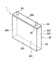
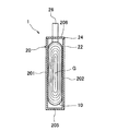
図2は、実施例の設計方法で設計することができる二次電池を例示する斜視図であり、図3はその中央縦断面図である。図示するように、この二次電池1は、正極シートと絶縁シートと負極シートと絶縁シートの組が偏平状に巻回された偏平電極体10と、偏平電極体10を収容する偏平な角型容器20とを備える。
【0012】
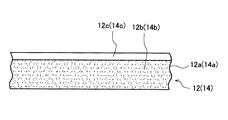
まず、偏平電極体10の構成および作製方法を説明する。偏平電極体10を構成する正極シート12の巻回前の平面図を図4に示す。長尺状アルミニウム箔からなる正極集電体12aの両面に正極活物質を含有するペーストを塗布して、正極集電体12aの両面に正極活物質層12bが形成されている。ここで、正極シート12の一方の長辺には、いずれの面にも正極活物質層12bが形成されていない活物質未塗工部12cが設けられている。
【0013】
負極シート14の構造は正極シート12と同様であるので、この負極シート14についても図4を用いて説明する。図4において括弧内に記された符号は負極シート14に対応するものである。長尺状銅箔からなる負極集電体14aの両面に負極活物質を含有するペーストを塗布して、負極集電体14aの両面に負極活物質層14bが形成されている。負極シート14の一方の長辺には、いずれの面にも負極活物質層14bが形成されていない活物質未塗工部14cが設けられている。
【0014】
なお、偏平電極体10の製造に使用する正極活物質としては、LiMn2O4、LiCoO2、LiNiO2等の従来のリチウムイオン二次電池に用いられる正極活物質の一種または二種以上を特に限定なく使用することができる。負極活物質としては、アモルファスカーボン、グラファイトカーボン等の従来のリチウムイオン二次電池に用いられる負極活物質の一種または二種以上を特に限定なく使用することができる。このような活物質を含有するペーストを調製するにあたっては、従来公知の結着剤、導電化剤、溶剤等を適宜使用することができる。これらペーストの集電体への塗布は、コンマコーター、ダイコーター等を用いて行うことができる。
【0015】
絶縁シート16としては多孔質ポリプロピレン樹脂シートを使用した。絶縁シート16の材質は、ポリプロピレン樹脂の他、ポリエチレン樹脂もしくはポリプロピレン樹脂とポリエチレン樹脂の混合物も用いることができる。この絶縁シート16の平面形状は、図4に示す正極シート12の正極活物質層12b、および負極シート14の負極活物質層14bが形成されている領域よりも幅、長さともに大きな形状とする。
図5に示すように、負極シート14と絶縁シート16と正極シート12と絶縁シート16を重ね合わせる。このとき、負極シート14の負極活性物質14bが塗布されている領域は、正極シート12の正極活性物質12bが塗布されている領域よりも幅、長さともに大きく、絶縁シート16は負極シート14の負極活性物質14bが塗布されている領域よりもさらに大きくなるようにしておく。ここで、正極シート12の活物質未塗工部12cと負極シート14の活物質未塗工部14cとが、絶縁シート16の一方の長辺および他方の長辺からそれぞれはみ出すように、両シート12,14を配置する。次いで、重ね合わせたシート12,16,14,16の組を巻回機等を用いて長辺方向に巻回する。この巻回体を径方向にプレスして、図1(a)に例示した横断面が偏平状の電極体10を作製する。ここで、偏平電極体10の幅(H)は50〜100mm、奥行(W)は100〜150mm、積層高さ(T)は10〜40mm、その電極体10の偏平面と角型容器の内壁との間のクリアランス(C)は−2〜+2mmの範囲で適当に組み合わせる。
なお、積層高さ(T)は、得られた偏平電極体10の厚さ方向に所定の(例えば1〜5kgf/cm2(9.8×104〜4.9×105Pa)、ここでは3kgf/cm2(2.94×105Pa)の)押圧力をかけた状態で測定した値を用いる。したがって、積層高さ(T)の測定時よりも大きな押圧力を偏平電極体10に加えながら角型容器20に収容した場合には、クリアランス(C)がマイナスの値となり得る。
【0016】
図2に示すように、角型容器20はアルミニウム製であって、有底四角筒状の電極体ケース22と、電極体ケース22の上端開口部を封止する蓋24とを備える。この容器20は6つ(3対)の平面部201〜206からなる直方体状である。平面部201と202、平面部203と204、平面部205と206(この平面部206は蓋24により形成されている)とはそれぞれ対向している。
図3に示すように、偏平電極体10は、その巻回中心(巻回軸)Gが横倒しとなるように容器20に収容されている。容器20の有する6つの平面部のうち最も面積の広い一対の平面部(最大平面部)201、202の内壁に、偏平電極体10の積層方向の両面(偏平面)が対面している。
この偏平電極体10には図示しない電解液が含浸されている。電解液としてはジエチルカーボネートとエチレンカーボネートとの7:3(体積比)混合溶媒に1mol/リットルのLiPF6を溶解させたもの等を用いることができる。
偏平電極体10を構成する正極シート12は、活物質未塗工部を利用して、角型容器20から突出する正極端子26に接続されている。負極シート14は、活物質未塗工部を利用して、負極端子28に接続されている。
【0017】
上記構成を有するリチウムイオン二次電池であって、その各部の寸法(H,T,WおよびCのうち一または二以上)が異なる何種類かのものにつき、それらの最大面圧(電池の満充電時において、電極体の偏平面中央付近と容器内壁との間に生じた面圧をいう。)と容量維持率Rとの関係を検討した。その結果、図6に示す特性図が得られた。ここで容量維持率Rとは、初期の充電完了後の電池容量を100%として、充放電を500サイクル繰返した後での充電完了後の電池容量の比率を示すものであって、電池性能の低下速度の目安とすることができる。
【0018】
円筒型に巻回された電極体を円筒容器に収容した電池の場合、偏平巻電極体のコーナー部や平坦面に相当する部分がなく、電極体に加わる圧縮力を均一化しやすい傾向にある。円筒型電極体を用いた電池では、偏平電極体を用いた電池に比べて電池反応の偏りが起こり難い。円筒型電池の場合、充放電を500サイクル繰返した後における容量維持率はほぼ80%程度である。角型電池の場合、500サイクル後の容量維持率をほぼ70%以上(より好ましくは80%以上)とすることができれば、円筒型電池と同等程度に電池反応が均一化されていると言える。
【0019】
この結果によれば、図6に示すように、最大面圧と容量維持率との間には一義的な関係がみられる。すなわち、最大面圧を400gf/cm2(3.92×104Pa)程度以上とすると500サイクル後の容積維持率が70%に達する。最大面圧が400gf/cm2(3.92×104Pa)未満であると、500サイクル後の容積維持率が70%に満たないことがわかる。
【0020】
上記構成を有するリチウムイオン二次電池の寸法を様々に変えて実験した結果を表1に示す。偏平電極体の幅(H)と、奥行(W)と、積層高さ(T)と、偏平電極体の偏平面と角型容器の内壁とのクリアランス(C)は、mmの単位である。本発明者らの研究によって、WHC/Tの値が重要であるとの知見が得られたので、表1には、WHC/Tの値が整理されている。それぞれの電池に対して500回の充放電サイクルを繰返して行い、サイクル試験前の電池容量(満充電後の電池容量)を100とし、サイクル試験後の電池容量(満充電後の電池容量)の比を求めるという方法で、容量維持率(R)を測定した。
【0021】
【表1】
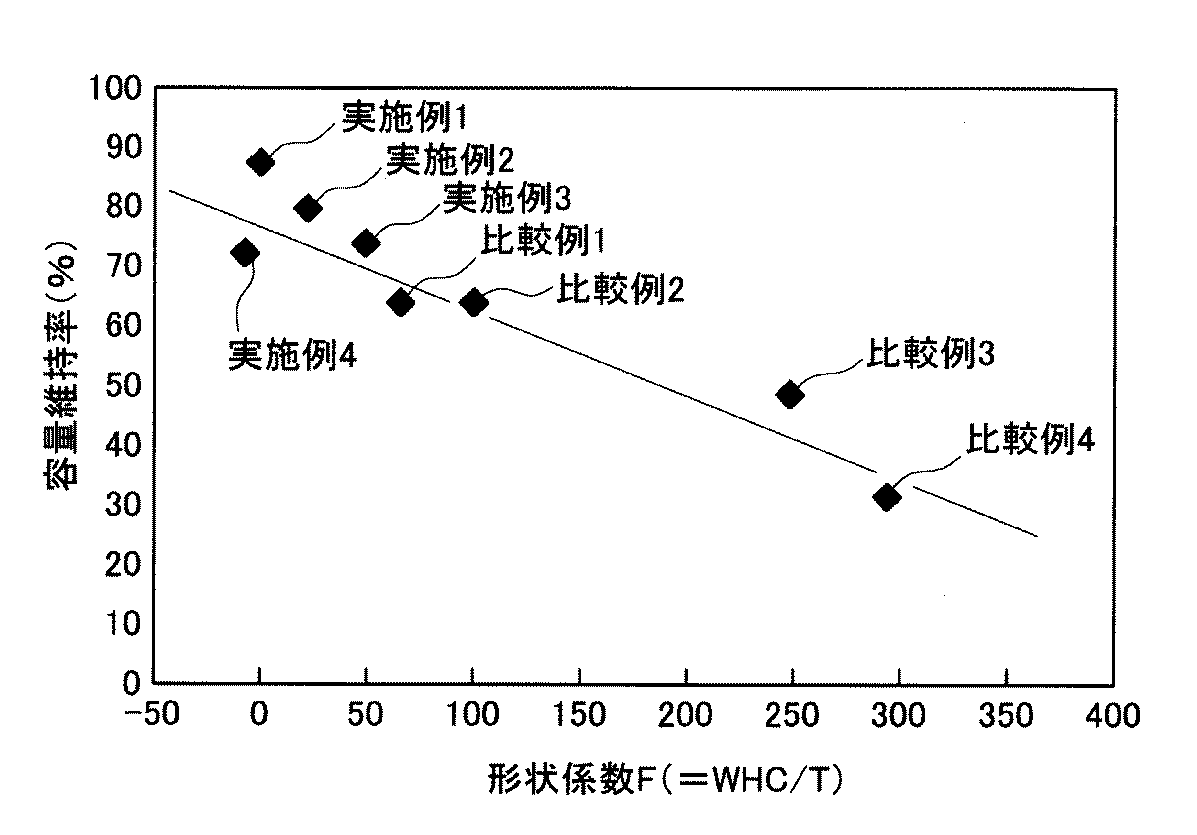
図7には、式(WHC/T)により算出される形状係数(F)の値と、容量維持率(R)の関係がプロットされている。
実施例1〜4では、WHC/Tの値が50以下であり、WHC/Tの値が50以下であれば容量維持率(R)が70%以上となる。実施例1で用いた電池では87%という高い数値が得られた。一般に、容量維持率(R)が70%以上となれば、実用上十分な耐久性を有しているといえる。比較例1〜4では、WHC/Tの値が50以上であり、WHC/Tの値が50以上であれば容量維持率(R)が70%以下にしかならない。
式(WHC/T)により算出される形状係数(F)が50以下であれば、容量維持率(R)が70%以上となり、電池反応が均一化され、電池として優れた特性を有することがわかる。WHC/Tの値を指標とし、これが基準値以下となる条件で各寸法を決定すると、電池性能の低下速度が遅くて耐久性が長い電池を設計できることがわかる。
【0023】
これらの実験例ではリチウムイオン二次電池を用いたが、本発明はニッケル水素電池、ニッケルカドミウム電池等の他の種類の二次電池にも適用することができる。正極および負極の活物質、集電体および端子ならびに絶縁シート等の材質や電解液の組成等は、二次電池の種類に応じて適当に選択される。
【0024】
以上、本発明の具体例を詳細に説明したが、これらは例示にすぎず、特許請求の範囲を限定するものではない。特許請求の範囲に記載の技術には、以上に例示した具体例を様々に変形、変更したものが含まれる。例えば、偏平電極体を、カットされた電極シートを多層に積層して形成することもできる。
また、本明細書または図面に説明した技術要素は、単独であるいは各種の組み合わせによって技術的有用性を発揮するものであり、出願時請求項記載の組み合わせに限定されるものではない。また、本明細書または図面に例示した技術は複数目的を同時に達成するものであり、そのうちの一つの目的を達成すること自体で技術的有用性を持つものである。
【図面の簡単な説明】
【図1】 (a)および(b)はそれぞれ偏平電極体を例示する斜視図である。
【図2】 本実施例に係る二次電池を示す斜視図である。
【図3】 図2の中央縦断面図である。
【図4】 電極体を構成する正極シートを示す平面図である。
【図5】 巻回前の電極体シート配置を示す断面図である。
【図6】 偏平型電極体における最大面圧と容量維持率の関係を示す図である。
【図7】 形状係数Fと容量維持率Rの関係を示す図である。
【符号の説明】
1:二次電池
10:偏平電極体
12:正極シート
14:負極シート
16:絶縁シート
20:容器
201,202:最大平面部(平坦面)
H:偏平電極体の幅
W:偏平電極体の奥行
T:偏平電極体の積層高さ
C:偏平電極体の偏平面と角型容器の内壁との間のクリアランス[0001]
BACKGROUND OF THE INVENTION
The present invention relates to a method for designing a flat prismatic secondary battery, and more particularly to a method for selecting preferred dimensions.
[0002]
[Prior art]
A prismatic secondary battery is configured by accommodating a flat electrode body in which a set of a positive electrode sheet, an insulating sheet, a negative electrode sheet, and an insulating sheet is laminated in a multilayered manner in a rectangular container. Generally, when a flat electrode body is accommodated in a rectangular container and impregnated with an electrolytic solution, the flat electrode body expands in the stacking height direction. Further, when charged, the flat electrode body expands.
In the case of a rectangular container, the distance between the two flat surfaces is likely to increase at the central portion, whereas it is difficult to expand at a portion near the side or corner. For this reason, when the flat electrode body expands, it is apt to be weakly compressed by the rectangular container at the central portion of the flat surface and strongly compressed at the portion close to the side.
In the portion where the compressive force is weak, the internal resistance of the electrode body tends to increase, and as a result, the battery reaction may proceed with a bias toward the portion where the compressive force is strong. If the battery reaction proceeds in a biased manner, the battery performance tends to deteriorate in a short time. For example, the battery capacity after completion of charging is rapidly reduced by repeating the charge / discharge cycle. When the flat electrode body is uniformly compressed and the battery reaction proceeds uniformly, the battery capacity after completion of charging can be slowed down by repeating the charge / discharge cycle, whereas it is compressed unevenly. Then, the battery reaction proceeds non-uniformly, and the battery capacity after completion of charging is rapidly reduced by repeating the charge / discharge cycle.
The relationship between the dimensions of the flat electrode body and the internal dimensions of the rectangular container is extremely important in maintaining battery performance because it is closely related to the compressed state of the flat electrode body, and must be selected correctly.
[0003]
A flat electrode body in which a set of a positive electrode sheet, an insulating sheet, a negative electrode sheet, and an insulating sheet is wound and laminated is often used. FIG. 1 illustrates a wound
[0004]
Japanese Patent Application Laid-Open No. 2001-67821 discloses a technique for making the compressed state of the flat electrode body uniform. In this technique, after the flat electrode body is inserted into the rectangular container, the flat surface of the rectangular container is pushed inward to form a concave shape.
[0005]
[Problems to be solved by the invention]
As described in Japanese Patent Application Laid-Open No. 2001-67821, the compression state of the flat electrode body is made uniform by adjusting the clearance between the flat surface of the flat electrode body and the inner surface of the rectangular container. Even if you know that you can do it, you don't know how much clearance you need. If the clearance is too large, the flat electrode body cannot be uniformly compressed. Even if the clearance is made too small, the flat electrode body cannot be uniformly compressed. Furthermore, the rectangular container may be deformed.
At present, every time a new type of battery is designed, a number of experiments are repeated to search for the optimum clearance by trial and error, and much man-hours and time are spent until the optimum clearance is searched.
There is a need for a technique for searching for a good clearance (C) in a short time between the flat surface of the flat electrode body closely related to the battery performance and the inner wall of the rectangular container.
[0006]
[Means and Actions for Solving the Problems]
In the present invention, when designing a rectangular secondary battery in which a flat electrode body is accommodated in a rectangular container, the flat surface defined by the width (H) and depth (W) of the flat electrode body is opposed to the flat surface. A method has been created in which the size of the clearance (C) between the inner wall of the rectangular container can be determined in a short time.
According to the study by the present inventors, the width (H) of the flat electrode body of the square secondary battery is 50 to 100 mm, the depth (W) is 100 to 150 mm, and 3 kgf / in the stacking direction of the flat electrode body. A square container that has a stacking height (T) of 10 to 40 mm measured with a pressing force of cm 2 and is opposed to the flat plane defined by the width (H) and depth (W). When the clearance (C) between the inner wall and the inner wall is -2 to +2 mm, the width (H), depth (W), and stacking height (T) of the flat electrode body vary depending on the type of battery. The flat surface defined by the width (H) and depth (W) of the flat electrode body under the condition that the value of WHC / T is −5.6 ≦ WHC / T ≦ 46.9 The size of the clearance (C) between the inner wall of the square container facing the eccentric plane It has been found that when selected, the size of the clearance that gives good results can be selected regardless of the battery type.
[0007]
In the method for designing a rectangular secondary battery according to
According to this method, since the range for searching for the optimum clearance (C) is narrowed down, the number of experiments for searching for the optimum clearance (C) can be reduced, and the optimum clearance (C) can be searched for in a short time. it can.
[0008]
According to the above method reporting, to a range for searching the optimum clearance (C) is narrowed clarity, it requires less number of experiments to search for the optimum clearance (C), a short time in an optimum clearance (C) Can be explored.
[0009]
DETAILED DESCRIPTION OF THE INVENTION
The present invention is also preferably implemented in the following forms.
(Embodiment 1) The square secondary battery of the present invention is a lithium ion secondary battery. Lithium ion secondary batteries have a problem in that battery performance tends to deteriorate due to uneven battery reaction. For this reason, the application effect of this invention is large.
[0010]
(Mode 2) The width (H) of the flat electrode body is selected from the range of 50 to 100 mm, the depth (W) is selected from the range of 100 to 150 mm, and the stacking height (T) is selected from the range of 10 to 40 mm. The clearance (C) between the flat surface of the flat electrode body and the inner wall of the rectangular container is selected from the range of −2 to +2 mm.
This battery has high practicality from the viewpoint of battery performance (capacity, etc.) and mountability to various devices (vehicles, etc.).
[0011]
【Example】
An embodiment embodying the present invention will be described below. In addition, the following description is an illustration and does not explain invention.
FIG. 2 is a perspective view illustrating a secondary battery that can be designed by the design method of the embodiment, and FIG. 3 is a central longitudinal sectional view thereof. As shown in the figure, the
[0012]
First, the configuration and manufacturing method of the
[0013]
Since the structure of the
[0014]
In addition, as a positive electrode active material used for manufacture of the
[0015]
A porous polypropylene resin sheet was used as the insulating
As shown in FIG. 5, the
The stacking height (T) is predetermined (for example, 1 to 5 kgf / cm 2 (9.8 × 10 4 to 4.9 × 10 5 Pa)) in the thickness direction of the obtained
[0016]
As shown in FIG. 2, the
As shown in FIG. 3, the
The
The
[0017]
Regarding the lithium ion secondary batteries having the above-described configuration, the maximum surface pressure (battery full capacity of the batteries) of several types having different dimensions (one or more of H, T, W, and C) is different. The relationship between the surface pressure generated between the vicinity of the center of the flat surface of the electrode body and the inner wall of the container during charging) and the capacity retention ratio R were examined. As a result, the characteristic diagram shown in FIG. 6 was obtained. Here, the capacity maintenance ratio R indicates the ratio of the battery capacity after completion of charge after 500 cycles of charge and discharge, assuming that the battery capacity after completion of initial charge is 100%. It can be a measure of the rate of decline.
[0018]
In the case of a battery in which an electrode body wound in a cylindrical shape is accommodated in a cylindrical container, there is no portion corresponding to a corner portion or a flat surface of the flat wound electrode body, and the compressive force applied to the electrode body tends to be uniform. In the battery using the cylindrical electrode body, the battery reaction is less likely to be biased than the battery using the flat electrode body. In the case of a cylindrical battery, the capacity retention rate after 500 cycles of charge / discharge is approximately 80%. In the case of a prismatic battery, if the capacity retention rate after 500 cycles can be made approximately 70% or more (more preferably 80% or more), it can be said that the battery reaction is uniformed to the same extent as that of a cylindrical battery.
[0019]
According to this result, as shown in FIG. 6, there is a unique relationship between the maximum surface pressure and the capacity retention rate. That is, when the maximum surface pressure is about 400 gf / cm 2 (3.92 × 10 4 Pa) or more, the volume retention after 500 cycles reaches 70%. When the maximum surface pressure is less than 400 gf / cm 2 (3.92 × 10 4 Pa), it can be seen that the volume retention after 500 cycles is less than 70%.
[0020]
Table 1 shows the results of experiments conducted with various dimensions of the lithium ion secondary battery having the above configuration. The width (H) of the flat electrode body, the depth (W), the stacking height (T), and the clearance (C) between the flat surface of the flat electrode body and the inner wall of the rectangular container are in units of mm. Since the inventors have found that the value of WHC / T is important, Table 1 summarizes the values of WHC / T. 500 cycles of charge / discharge cycles are repeated for each battery, the battery capacity before the cycle test (battery capacity after full charge) is set to 100, and the battery capacity after the cycle test (battery capacity after full charge) is The capacity retention ratio (R) was measured by a method of determining the ratio.
[0021]
[Table 1]
FIG. 7 plots the relationship between the value of the shape factor (F) calculated by the equation (WHC / T) and the capacity retention rate (R).
In Examples 1 to 4, when the value of WHC / T is 50 or less and the value of WHC / T is 50 or less, the capacity retention ratio (R) is 70% or more. In the battery used in Example 1, a high value of 87% was obtained. Generally, if the capacity retention ratio (R) is 70% or more, it can be said that the battery has sufficient practical durability. In Comparative Examples 1 to 4, when the value of WHC / T is 50 or more and the value of WHC / T is 50 or more, the capacity retention ratio (R) is only 70% or less.
If the shape factor (F) calculated by the formula (WHC / T) is 50 or less, the capacity retention rate (R) is 70% or more, the battery reaction is uniformed, and the battery has excellent characteristics. Recognize. When each dimension is determined under the condition that the value of WHC / T is the reference value or less using the value of WHC / T, it can be seen that a battery having a long battery life and a low durability can be designed.
[0023]
In these experimental examples, lithium ion secondary batteries were used, but the present invention can also be applied to other types of secondary batteries such as nickel metal hydride batteries and nickel cadmium batteries. The materials of the positive and negative electrode active materials, current collectors and terminals, insulating sheets, and the like, the composition of the electrolytic solution, and the like are appropriately selected according to the type of the secondary battery.
[0024]
Specific examples of the present invention have been described in detail above, but these are merely examples and do not limit the scope of the claims. The technology described in the claims includes various modifications and changes of the specific examples illustrated above. For example, the flat electrode body can be formed by laminating cut electrode sheets in multiple layers.
In addition, the technical elements described in the present specification or the drawings exhibit technical usefulness alone or in various combinations, and are not limited to the combinations described in the claims at the time of filing. In addition, the technology illustrated in the present specification or the drawings achieves a plurality of objects at the same time, and has technical utility by achieving one of the objects.
[Brief description of the drawings]
FIGS. 1A and 1B are perspective views illustrating flat electrode bodies, respectively.
FIG. 2 is a perspective view showing a secondary battery according to the present embodiment.
FIG. 3 is a central longitudinal sectional view of FIG. 2;
FIG. 4 is a plan view showing a positive electrode sheet constituting an electrode body.
FIG. 5 is a cross-sectional view showing an arrangement of electrode body sheets before winding.
FIG. 6 is a diagram showing the relationship between the maximum surface pressure and the capacity retention rate in a flat electrode body.
7 is a diagram showing a relationship between a shape factor F and a capacity maintenance rate R. FIG.
[Explanation of symbols]
1: Secondary battery 10: Flat electrode body 12: Positive electrode sheet 14: Negative electrode sheet 16: Insulating sheet 20:
H: Width of flat electrode body W: Depth of flat electrode body T: Stack height of flat electrode body C: Clearance between flat surface of flat electrode body and inner wall of square container
Claims (1)
その角型二次電池の偏平電極体は、幅(H)が50〜100mmであり、
奥行(W)が100〜150mmであり、
その偏平電極体の積層方向に3kgf/cm 2 の押圧力をかけた状態で測定した積層高さ(T)が10〜40mmであり、
幅(H)および奥行(W)によって規定される偏平面とその偏平面に対向する角型容器の内壁との間のクリアランス(C)が−2〜+2mmであり、
その角型二次電池の設計方法は、
その偏平電極体の幅(H)と、奥行(W)と、その偏平電極体の積層方向に3kgf/cm 2 の押圧力をかけた状態で測定した積層高さ(T)と、幅(H)および奥行(W)によって規定される偏平面とその偏平面に対向する角型容器の内壁との間のクリアランス(C)を、WHC/Tの値が−5.6≦WHC/T≦46.9となるという条件下で選択することを特徴とする角型二次電池の設計方法。A method for designing a rectangular secondary battery in which a flat electrode body in which a set of a positive electrode sheet, an insulating sheet, a negative electrode sheet, and an insulating sheet is laminated in multiple layers is housed in a rectangular container ,
The flat electrode body of the rectangular secondary battery has a width (H) of 50 to 100 mm,
Depth (W) is 100-150mm,
The lamination height (T) measured in a state where a pressing force of 3 kgf / cm 2 is applied in the lamination direction of the flat electrode body is 10 to 40 mm,
The clearance (C) between the flat surface defined by the width (H) and the depth (W) and the inner wall of the rectangular container facing the flat surface is −2 to +2 mm ,
The design method of the prismatic secondary battery is
The width (H), depth (W) of the flat electrode body, stacking height (T) measured with a pressing force of 3 kgf / cm 2 in the stacking direction of the flat electrode body, and width (H ) And the depth (W) and the clearance (C) between the inner surface of the rectangular container facing the eccentric plane and the value of WHC / T is −5.6 ≦ WHC / T ≦ 46 .9 , a method for designing a prismatic secondary battery, which is selected under the condition of 9 .
Priority Applications (1)
| Application Number | Priority Date | Filing Date | Title |
|---|---|---|---|
| JP2002204562A JP4313992B2 (en) | 2002-07-12 | 2002-07-12 | Design method for prismatic secondary battery |
Applications Claiming Priority (1)
| Application Number | Priority Date | Filing Date | Title |
|---|---|---|---|
| JP2002204562A JP4313992B2 (en) | 2002-07-12 | 2002-07-12 | Design method for prismatic secondary battery |
Publications (2)
| Publication Number | Publication Date |
|---|---|
| JP2004047332A JP2004047332A (en) | 2004-02-12 |
| JP4313992B2 true JP4313992B2 (en) | 2009-08-12 |
Family
ID=31710128
Family Applications (1)
| Application Number | Title | Priority Date | Filing Date |
|---|---|---|---|
| JP2002204562A Expired - Fee Related JP4313992B2 (en) | 2002-07-12 | 2002-07-12 | Design method for prismatic secondary battery |
Country Status (1)
| Country | Link |
|---|---|
| JP (1) | JP4313992B2 (en) |
Families Citing this family (16)
| Publication number | Priority date | Publication date | Assignee | Title |
|---|---|---|---|---|
| JP5261869B2 (en) * | 2005-10-07 | 2013-08-14 | 株式会社Gsユアサ | Nonaqueous electrolyte secondary battery |
| JP4379432B2 (en) | 2006-05-10 | 2009-12-09 | トヨタ自動車株式会社 | Power output device, vehicle equipped with the same, and secondary battery setting method |
| CA2709117C (en) * | 2007-12-25 | 2016-08-09 | Byd Company Limited | Construction of electrochemical storage cell with conductive block |
| JP4716138B2 (en) * | 2008-01-11 | 2011-07-06 | トヨタ自動車株式会社 | Electrode winding device, deviation detection method between band electrode and band separator, deviation amount measuring method, deviation amount correcting method, and electrode winding method |
| JP4835956B2 (en) | 2008-07-02 | 2011-12-14 | トヨタ自動車株式会社 | battery |
| CN102150313A (en) * | 2009-01-29 | 2011-08-10 | 松下电器产业株式会社 | Nonaqueous electrolyte secondary battery and manufacturing method therefor |
| JPWO2011016183A1 (en) * | 2009-08-07 | 2013-01-10 | パナソニック株式会社 | Nonaqueous electrolyte secondary battery |
| KR101283091B1 (en) * | 2010-12-08 | 2013-07-05 | 도요타지도샤가부시키가이샤 | Lithium ion secondary battery |
| JP5998368B2 (en) * | 2012-12-11 | 2016-09-28 | エス・イー・アイ株式会社 | Method for manufacturing electrochemical device |
| JP6550848B2 (en) * | 2015-03-30 | 2019-07-31 | 三洋電機株式会社 | Prismatic secondary battery |
| JP2017228391A (en) * | 2016-06-21 | 2017-12-28 | 本田技研工業株式会社 | Manufacturing method of square battery, manufacturing method of vehicle, design support method of square battery, square battery, and vehicle |
| CN110190221B (en) * | 2019-05-14 | 2020-09-04 | 宁德时代新能源科技股份有限公司 | Battery module and battery pack |
| WO2021065128A1 (en) * | 2019-09-30 | 2021-04-08 | 三洋電機株式会社 | Method for producing nonaqueous electrolyte secondary battery, and nonaqueous electrolyte secondary battery |
| CN113258121B (en) * | 2021-05-17 | 2022-07-12 | 湖北亿纬动力有限公司 | Method for calculating width of winding type bare cell after hot pressing |
| WO2023074559A1 (en) * | 2021-10-25 | 2023-05-04 | 株式会社Gsユアサ | Power storage element |
| JP2023133242A (en) * | 2022-03-11 | 2023-09-22 | 三洋化成工業株式会社 | Battery module and manufacturing method thereof |
-
2002
- 2002-07-12 JP JP2002204562A patent/JP4313992B2/en not_active Expired - Fee Related
Also Published As
| Publication number | Publication date |
|---|---|
| JP2004047332A (en) | 2004-02-12 |
Similar Documents
| Publication | Publication Date | Title |
|---|---|---|
| US8187738B2 (en) | Spirally-rolled electrodes with separator and the batteries therewith | |
| US8574736B2 (en) | Hybrid-typed electrode assembly of capacitor-battery structure | |
| JP4313992B2 (en) | Design method for prismatic secondary battery | |
| US6767667B1 (en) | Sealed battery | |
| EP1318561A1 (en) | Coin-shaped battery | |
| US11742548B2 (en) | Electrical storage device and electrical storage module | |
| JP3589021B2 (en) | Lithium ion secondary battery | |
| JP2019160587A (en) | Nonaqueous electrolyte secondary battery and battery pack including the same | |
| JP2002050322A (en) | Sealed square flat cell | |
| JP3114646B2 (en) | Secondary battery and manufacturing method thereof | |
| CN110970653A (en) | Nonaqueous electrolyte secondary battery | |
| US20140170471A1 (en) | Electrode plate, layered electrode group, battery, and cylindrical battery | |
| JP3533903B2 (en) | Non-cylindrical battery and method of manufacturing the same | |
| JP4088732B2 (en) | Secondary battery | |
| JP2003257471A (en) | Storage battery element and its manufacturing method | |
| JP2022127181A (en) | Secondary battery and manufacturing method for secondary battery | |
| JP2001291526A (en) | Sealed battery and its manufacturing method | |
| JP3511709B2 (en) | Thin battery | |
| JP3166487B2 (en) | Thin battery | |
| JP2506572Y2 (en) | Lithium ion secondary battery | |
| CN215680755U (en) | Lithium ion battery and vehicle | |
| JP7365562B2 (en) | Wound electrode body for secondary batteries | |
| US11387495B2 (en) | Non-aqueous electrolyte secondary battery | |
| JP2005243274A (en) | Nonaqueous rectangular secondary battery | |
| JPH0251875A (en) | Nonaqueous electrolyte secondary battery |
Legal Events
| Date | Code | Title | Description |
|---|---|---|---|
| A621 | Written request for application examination |
Free format text: JAPANESE INTERMEDIATE CODE: A621 Effective date: 20050308 |
|
| A977 | Report on retrieval |
Free format text: JAPANESE INTERMEDIATE CODE: A971007 Effective date: 20071029 |
|
| A131 | Notification of reasons for refusal |
Free format text: JAPANESE INTERMEDIATE CODE: A131 Effective date: 20080701 |
|
| A521 | Request for written amendment filed |
Free format text: JAPANESE INTERMEDIATE CODE: A523 Effective date: 20080827 |
|
| A521 | Request for written amendment filed |
Free format text: JAPANESE INTERMEDIATE CODE: A523 Effective date: 20080827 |
|
| A02 | Decision of refusal |
Free format text: JAPANESE INTERMEDIATE CODE: A02 Effective date: 20081104 |
|
| A521 | Request for written amendment filed |
Free format text: JAPANESE INTERMEDIATE CODE: A523 Effective date: 20081224 |
|
| A521 | Request for written amendment filed |
Free format text: JAPANESE INTERMEDIATE CODE: A523 Effective date: 20090218 |
|
| A911 | Transfer to examiner for re-examination before appeal (zenchi) |
Free format text: JAPANESE INTERMEDIATE CODE: A911 Effective date: 20090324 |
|
| TRDD | Decision of grant or rejection written | ||
| A01 | Written decision to grant a patent or to grant a registration (utility model) |
Free format text: JAPANESE INTERMEDIATE CODE: A01 Effective date: 20090428 |
|
| A01 | Written decision to grant a patent or to grant a registration (utility model) |
Free format text: JAPANESE INTERMEDIATE CODE: A01 |
|
| A61 | First payment of annual fees (during grant procedure) |
Free format text: JAPANESE INTERMEDIATE CODE: A61 Effective date: 20090518 |
|
| FPAY | Renewal fee payment (event date is renewal date of database) |
Free format text: PAYMENT UNTIL: 20120522 Year of fee payment: 3 |
|
| R151 | Written notification of patent or utility model registration |
Ref document number: 4313992 Country of ref document: JP Free format text: JAPANESE INTERMEDIATE CODE: R151 |
|
| FPAY | Renewal fee payment (event date is renewal date of database) |
Free format text: PAYMENT UNTIL: 20120522 Year of fee payment: 3 |
|
| FPAY | Renewal fee payment (event date is renewal date of database) |
Free format text: PAYMENT UNTIL: 20130522 Year of fee payment: 4 |
|
| R250 | Receipt of annual fees |
Free format text: JAPANESE INTERMEDIATE CODE: R250 |
|
| FPAY | Renewal fee payment (event date is renewal date of database) |
Free format text: PAYMENT UNTIL: 20140522 Year of fee payment: 5 |
|
| R250 | Receipt of annual fees |
Free format text: JAPANESE INTERMEDIATE CODE: R250 |
|
| R250 | Receipt of annual fees |
Free format text: JAPANESE INTERMEDIATE CODE: R250 |
|
| R250 | Receipt of annual fees |
Free format text: JAPANESE INTERMEDIATE CODE: R250 |
|
| R250 | Receipt of annual fees |
Free format text: JAPANESE INTERMEDIATE CODE: R250 |
|
| R250 | Receipt of annual fees |
Free format text: JAPANESE INTERMEDIATE CODE: R250 |
|
| R250 | Receipt of annual fees |
Free format text: JAPANESE INTERMEDIATE CODE: R250 |
|
| LAPS | Cancellation because of no payment of annual fees |