JP4088732B2 - Secondary battery - Google Patents
Secondary battery Download PDFInfo
- Publication number
- JP4088732B2 JP4088732B2 JP35360198A JP35360198A JP4088732B2 JP 4088732 B2 JP4088732 B2 JP 4088732B2 JP 35360198 A JP35360198 A JP 35360198A JP 35360198 A JP35360198 A JP 35360198A JP 4088732 B2 JP4088732 B2 JP 4088732B2
- Authority
- JP
- Japan
- Prior art keywords
- electrode group
- battery
- pair
- thickness
- battery container
- Prior art date
- Legal status (The legal status is an assumption and is not a legal conclusion. Google has not performed a legal analysis and makes no representation as to the accuracy of the status listed.)
- Expired - Fee Related
Links
Images


Classifications
-
- H—ELECTRICITY
- H01—ELECTRIC ELEMENTS
- H01M—PROCESSES OR MEANS, e.g. BATTERIES, FOR THE DIRECT CONVERSION OF CHEMICAL ENERGY INTO ELECTRICAL ENERGY
- H01M50/00—Constructional details or processes of manufacture of the non-active parts of electrochemical cells other than fuel cells, e.g. hybrid cells
- H01M50/10—Primary casings; Jackets or wrappings
- H01M50/14—Primary casings; Jackets or wrappings for protecting against damage caused by external factors
-
- H—ELECTRICITY
- H01—ELECTRIC ELEMENTS
- H01M—PROCESSES OR MEANS, e.g. BATTERIES, FOR THE DIRECT CONVERSION OF CHEMICAL ENERGY INTO ELECTRICAL ENERGY
- H01M50/00—Constructional details or processes of manufacture of the non-active parts of electrochemical cells other than fuel cells, e.g. hybrid cells
- H01M50/10—Primary casings; Jackets or wrappings
- H01M50/102—Primary casings; Jackets or wrappings characterised by their shape or physical structure
- H01M50/107—Primary casings; Jackets or wrappings characterised by their shape or physical structure having curved cross-section, e.g. round or elliptic
-
- Y—GENERAL TAGGING OF NEW TECHNOLOGICAL DEVELOPMENTS; GENERAL TAGGING OF CROSS-SECTIONAL TECHNOLOGIES SPANNING OVER SEVERAL SECTIONS OF THE IPC; TECHNICAL SUBJECTS COVERED BY FORMER USPC CROSS-REFERENCE ART COLLECTIONS [XRACs] AND DIGESTS
- Y02—TECHNOLOGIES OR APPLICATIONS FOR MITIGATION OR ADAPTATION AGAINST CLIMATE CHANGE
- Y02E—REDUCTION OF GREENHOUSE GAS [GHG] EMISSIONS, RELATED TO ENERGY GENERATION, TRANSMISSION OR DISTRIBUTION
- Y02E60/00—Enabling technologies; Technologies with a potential or indirect contribution to GHG emissions mitigation
- Y02E60/10—Energy storage using batteries
-
- Y—GENERAL TAGGING OF NEW TECHNOLOGICAL DEVELOPMENTS; GENERAL TAGGING OF CROSS-SECTIONAL TECHNOLOGIES SPANNING OVER SEVERAL SECTIONS OF THE IPC; TECHNICAL SUBJECTS COVERED BY FORMER USPC CROSS-REFERENCE ART COLLECTIONS [XRACs] AND DIGESTS
- Y02—TECHNOLOGIES OR APPLICATIONS FOR MITIGATION OR ADAPTATION AGAINST CLIMATE CHANGE
- Y02P—CLIMATE CHANGE MITIGATION TECHNOLOGIES IN THE PRODUCTION OR PROCESSING OF GOODS
- Y02P70/00—Climate change mitigation technologies in the production process for final industrial or consumer products
- Y02P70/50—Manufacturing or production processes characterised by the final manufactured product
Landscapes
- Chemical & Material Sciences (AREA)
- Chemical Kinetics & Catalysis (AREA)
- Electrochemistry (AREA)
- General Chemical & Material Sciences (AREA)
- Sealing Battery Cases Or Jackets (AREA)
- Secondary Cells (AREA)
Description
【0001】
【発明の属する技術分野】
本発明は、非真円筒形の二次電池に関する。
【0002】
【従来の技術】
近年、携帯用無線電話装置、携帯用パーソナルコンピュータ、携帯用ビデオカメラ等の電子機器の小型化にともなって、高エネルギー密度を有しかつ軽量性に優れ、さらに充放電が可能な二次電池が実用化されている。特に、リチウム二次電池(リチウムイオン二次電池)は、駆動機器、携帯電子機器、電気自動車等の電源として種々の分野で用いられている。
【0003】
長円筒形のリチウム二次電池では、長円形の横断面図を有する一様な厚みの電池容器内に電極群が収納されている。電極群は、金属箔からなる帯状の正極集電体の表面に正極活物質を保持させた正極シートと、金属箔からなる帯状の負極集電体の表面に炭素材料を保持させた負極シートとを、セパレータを介して、円筒形に巻回または積層し、さらにその円筒形の電極群を押しつぶして長円筒形に成形したものである。電極群を収納した電池容器内には、さらに有機電解液が充填される。このような電池容器の上部開口部には、電池蓋板が溶接により液密に取り付けられる。電池蓋板には正極端子および負極端子が設けられている。
【0004】
【発明が解決しようとする課題】
リチウム二次電池では、充放電サイクルを繰り返すことにより負極および正極で有機電解液が分解し、炭酸ガスを主成分とするガスが発生する。しかしながら、リチウム二次電池では、鉛電池、ニッケルカドミウム電池およびニッケル水素電池等の水溶系二次電池のように負極によるガス吸収が行われない。そのため、発生したガスは電池内に残留し、ガスの発生の進行とともに電池の内圧が増大する。
【0005】
また、リチウム二次電池においては、大電流で充放電を繰り返すことにより温度が上昇する。それにより、電極群が膨張し電池容器の内面を圧迫する。
【0006】
これらの結果、図7(a)に示す一様な厚みを有する長円筒形の電池容器20においては、図7(b)に示すように、平面部に膨れが発生する場合がある。
【0007】
このような電池容器20の平面部が膨れるという課題に対し、電池容器20の厚みを一様に厚くすると膨れは少なくなるが、重量が大幅に増加する。
【0008】
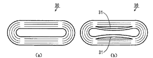
一方、図8(a)に示すように、正常な状態の電極群30においては正極シート、負極シートおよびセパレータが密接して巻回または積層されている。しかしながら、図8(b)に示すように、電極群30の内面が内側に膨らむことにより電極群30内に隙間31が生じる場合がある。隙間31は電極間の隙間であるため、充放電反応が部分的に妨げられる。その結果、電池容量が低下する。
【0009】
このような電極群30における隙間31の発生を防止するため、図9(a)に示すように、電極群30の平面部をテープ32で固定したり、図9(b)に示すように、電極群30の中心の空間に芯として弾性ばね部材33を挿入することが行われている。しかしながら、これらの方法は製造時の工数および部品コストの増大を招くことになる。
【0010】
本発明の目的は、低コスト化を妨げることなくかつ重量の大幅な増加を招くことなく電池容器の膨れが防止された二次電池を提供することである。
【0011】
本発明の他の目的は、低コスト化を妨げることなくかつ重量の大幅な増加を招くことなく電池容器の膨れおよび電極群における隙間の発生が防止された二次電池を提供することである。
【0012】
【課題を解決するための手段および発明の効果】
本発明に係る二次電池は、対向する一対の平面部および一対の平面部の両側をつなぐ一対の半円筒状側面部からなる非真円筒形の電池容器に長円筒形の電極群を収納し、前記電池容器と電池蓋とをレーザー溶接してなる二次電池において、電池容器の各平面部の厚みが各半円筒状側面部の厚みよりも大きいものである。
【0013】
本発明に係る二次電池では、電池容器の変形し易い平面部の厚みが半円筒状側面部の厚みよりも厚くなっているため、電池容器内でのガスの発生または電極群の膨張により電池容器の平面部が圧迫された場合でも、電池容器の膨れが防止される。
【0014】
また、強度の高い一対の半円筒状側面部の厚みは、平面部の厚みに比べて小さくなっているため、電池容器の全体の強度が確保されつつ電池容器の重量が大幅に増加しない。
【0015】
特に、一対の平面部の外面と一対の半円筒状側面部の外面とが面一につながり、一対の平面部の内面が一対の半円筒状側面部の内面よりも内側に膨出していることが好ましい。
【0016】
長円筒形の電極群の両側の曲面部分では、中央部の平坦部分に比べて緊迫度が高くなっている。そのため、電極群の両側の曲面部分では隙間が生じにくいが、電極群の中央部の平坦部分では隙間が生じやすい。そこで、電池容器の平坦部の内面が曲面部の内面より内側に膨出することにより、電極群の中央部の平坦部分が電池容器の平面部により内側に押圧され、電極群の中央部の平坦部分の緊迫度が高くなる。それにより、電極群の両側の曲面部分および中央部の平坦部分において緊迫度が均一化される。その結果、電極群における隙間の発生が防止される。
【0017】
この場合、電極群の中央部の平坦部分の緊迫度を高めるために追加の部品および追加の工程が必要ないので、低コスト化が妨げられない。
【0018】
さらに、一対の半円筒状側面部の内面の半径Rおよび一対の平面部の内面間の距離Aが、
1.58<A/R<2
になる関係を満足することが好ましい。
【0019】
この場合、十分な電池容量を確保しつつ、電池容器の膨れおよび電極群における隙間の発生を防止することができる。
【0020】
また、各半円筒状側面部の厚みCに対する各平面部の厚みBの比B/Cが、
1.0<B/C<6.0
なる関係を満足することが好ましい。
【0021】
この場合も、十分な電池容量を確保しつつ、電池容器の膨れおよび電極群における隙間の発生を防止することができる。
【0022】
【発明の実施の形態】
以下、本発明に係る二次電池の一例としてリチウム二次電池について説明する。
【0023】
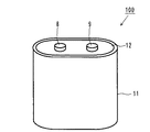
図1は長円筒形のリチウム二次電池の外観斜視図である。図1に示すように、リチウム二次電池100の電池容器11の上部開口部に、電池蓋板12がレーザー溶接により液密に取り付けられている。電池蓋板12には正極端子8および負極端子9が設けられている。
【0024】
図2は図1の電池容器の横断面図である。なお、図2において電池容器内部の詳細な構成を省略している。
【0025】
図2に示すように、電池容器11は、対向する一対の平面部11a、およびそれらの平面部11aの両側をつなぐ一対の半円筒部11bからなる。平面部11aの厚みBは半円筒部11bの厚みCより厚く形成される。
【0026】
このように、電池容器11の変形しやすい平面部11aの厚みBが半円筒部11bの厚みCよりも厚くなっているため、電池容器11内でのガスの発生または電極群の膨張により電池ケース11の平面部11aが圧迫された場合でも、電池容器11の膨れが防止される。
【0027】
リチウム二次電池100の電池容器11内には電極群および有機電解液が収納されている。電極群は、例えば以下のようにして作製する。
【0028】
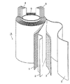
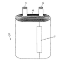
図3は電極群の分解斜視図であり、図4は電極群の斜視図である。図3に示すように、まず正極シート1と負極シート3とを、セパレータ2を介して、巻芯6を中心として渦巻き状に巻回し、円筒形の電極群10を作製する。なお、正極シート1には正極リード端子4が溶接されており、負極シート3には負極リード端子5が溶接されている。
【0029】
正極シート1は、アルミニウム基板(アルミニウム箔)からなる正極集電体の片面または両面に、正極活物質となるリチウムコバルト複合酸化物(LiCoO2 )を導電剤とともに結着剤を用いて保持させたものである。
【0030】
負極シート3は、銅基板(銅箔)からなる負極集電体の片面または両面に、負極炭素材料としての黒鉛を結着剤を用いて保持させたものである。セパレータ2は、ポリエチレン性の微多孔膜により形成される。
【0031】
次に、図3に示すように円筒形の電極群10の外周部をテープ7で固定した後押しつぶし、長円形の横断面を有する電極群10に成形する。
【0032】
以上のようにして作製した電極群10を、長円筒形の横断面を有する図2の電池容器11に収納する。さらに、電池容器11内に有機電解液を充填した後、電池容器11の上部開口部に、レーザー溶接により電池蓋板12を取り付ける。電池蓋板12の正極端子8および負極端子9に、電極群10の正極リード端子4および負極リード端子5をそれぞれ接続する。
【0033】
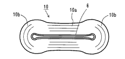
図5は電池容器に収納された状態の電極群の横断面図である。
図5に示すように、電極群10は中央部の平坦部分10aおよびその両側の曲面部分10bからなる。図2の電池容器11の平面部11aおよび曲面部11bの形状に対して、電極群10の中央部の平坦部分10aは両側の曲面部分10bに対して内側に凹入している。これは、電極群10の平坦部分10aが電池容器11の平面部11aにより押圧されたからである。
【0034】
このように、電極群10の平坦部分10aが電池容器11の平面部11aにより押圧されるため、電極群10の平坦部分10aの緊迫度が高くなる。それにより、電極群10の平坦部分10aおよび曲面部分10bにおいて緊迫度が均一化される。その結果、電極群10における隙間の発生が防止される。これにより、充放電反応が電極群10の全体において均一に行われ、電池特性が改善される。
【0035】
さらに、電極群10内の隙間の発生を防止するために従来用いていたテープや弾性ばね部材が不要となるため、工程数の削減およびコストの低減が可能になる。
【0036】
さらに、電極群10の曲面部分10bは押圧されないため、曲面部分10bの中心部の圧迫が少なくなる。そのため、曲面部分10bにおいて、電極10が折れたり、活物質が脱落したりすることがなくなる。
【0037】
【実施例】
ここで、図2の電池容器11を用いたリチウム二次電池において電池容器11の平面部11aの厚みBを変えて性能試験を行った。
【0038】
各々のリチウム二次電池の幅w130mm、厚みdは50mm、高さは210mmである。電池容器11の材質には、アルミニウムとマンガンとの合金(A3003)を用いた。
【0039】
電池容器11の半円筒部11bの厚みCは1.0mm、半円筒部11bの内面の半径Rは48mm、平面部11aの幅Dは65mmである。
【0040】
また、各々のリチウム二次電池の電池容器11内には、図3および図5に示す電極群10が収納されており、さらに有機電解液が充填されている。電極群10は、正極活物質としてLiCoO2 を含み、負極活物質として黒鉛を含む。また、有機電解液は、1MのLiPF6 を含むエチレンカーボネートおよびジエチルカーボネートの混合液であり、エチレンカーボネートおよびジエチルカーボネートの体積比は1:1である。
【0041】
性能試験では、各々のリチウム二次電池について、電圧4.1Vまで定電流20Aで充電を行った後、電圧2.7Vまで定電流20Aで放電するサイクルを100回繰り返し、サイクル試験前後の電池容量および厚みを測定した。温度は25℃である。各条件での試験数は、3個ずつであり、平均値を求めた。
【0042】
性能試験の結果を表1に示す。
【0043】
【表1】
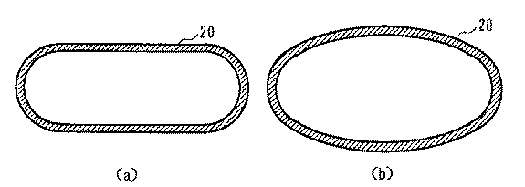
表1中のAおよびBは、図2の平面部11aの内面間の距離Aおよび平面部11bの厚みBにそれぞれ対応している。さらに、T値は式(1)から得られる値であり、電池容器11の内部容量と強度の関係を示すパラメータである。
【0045】
T=A/R ・・・ (1)
条件1では、T値が2(B/C=1.0)であり電池容器11の平面部11aの厚みBと半円筒部11bの厚みCとが同一である。そのため、電池容器11の強度が弱く、100サイクル充放電後の電池容器11の厚みdが55mmと5mm膨らんでいる。T値が小さくなるほど、平面部11aの厚みBが厚くなり強度が向上する。そのため、条件1〜6の結果からわかるように、100サイクル充放電後の電池容器11の厚みdの変化も小さくなる。
【0046】
また、T値が小さくなると、平面部11aの内面間の距離Aが小さくなり、電池容器11内の容積が低下する。このため、電池容器11内に収納できる電極群10の体積が低下し初期電池容量が低下する。
【0047】
条件4に示すようにT値が1.75(B/C=4.0)の場合、初期電池容量は110Ahであり、条件1〜3と比較してほとんど低下していない。これは、条件1の場合に電極群10の中心に約6mmあった空間が少しずつ狭くなることにより条件2〜4においても条件1と同一の体積の電極群10を電池容器11内に収納できるからである。すなわち、T値が1.75以上であれば、電極群10の中心の空間が減少するのみで、電極群10の体積は変わらない。したがって、初期電池容量の低下がほとんど生じない。
【0048】
また、100サイクル充放電後の電池容量は、T値が1.92(B/C=2.0)の条件2からT値が1.67(B/C=5.0)の条件5の範囲で高くなっている。T値が1.92を越えると電池容量が低下するのは、電池容器11が膨れるために電極群10の電極間に隙間が生じて内部抵抗が高くなったためであると考えられる。また、T値が1.58(B/C=6.0)未満では初期電池容量が小さいために100サイクル充放電後の電池容量も小さくなる。
【0049】
上記結果から、1.58<T<2の範囲において、電池容器11の膨れがほとんど生じず、かつ十分な電池容量が得られることがわかる。
【0050】
図6(a),(b)は側面部が複数の平面を組み合わせて構成された参考図、図6(c)は側面部が平面と曲面とを組み合わせて構成された参考図である。
【図面の簡単な説明】
【図1】 本発明の一実施例における長円筒形のリチウム二次電池の外観斜視図である。
【図2】 図1の電池容器の横断面図である。
【図3】 電極群の分解斜視図である。
【図4】 電極群の斜視図である。
【図5】 電池容器に収納された状態の電極群の横断面図である。
【図6】 参考図である。
【図7】 電池容器の変形を説明するための横断面図である。
【図8】 電極群に生ずる隙間を説明するための平面図である。
【図9】 図8の電極群に生ずる隙間の防止策を説明するための平面図である。
【符号の説明】
10 電極群
10a 平坦部分
10b 曲面部分
11 電池容器
11a 平面部
11b 半円筒部
A 内面間の距離
R 内面半径[0001]
BACKGROUND OF THE INVENTION
The present invention relates to a non-true cylindrical secondary battery.
[0002]
[Prior art]
In recent years, with the downsizing of electronic devices such as portable radiotelephone devices, portable personal computers, portable video cameras, etc., secondary batteries having high energy density, excellent light weight, and capable of charging / discharging have become available. It has been put into practical use. In particular, lithium secondary batteries (lithium ion secondary batteries) are used in various fields as power sources for driving devices, portable electronic devices, electric vehicles and the like.
[0003]
In a long cylindrical lithium secondary battery, an electrode group is housed in a battery container having a uniform thickness and having an elliptical cross-sectional view. The electrode group includes a positive electrode sheet in which a positive electrode active material is held on the surface of a strip-shaped positive electrode current collector made of metal foil, and a negative electrode sheet in which a carbon material is held on the surface of a strip-shaped negative electrode current collector made of metal foil Is wound or laminated into a cylindrical shape through a separator, and the cylindrical electrode group is further crushed to be formed into a long cylindrical shape. The battery container containing the electrode group is further filled with an organic electrolyte. A battery cover plate is liquid-tightly attached to the upper opening of such a battery container by welding. The battery cover plate is provided with a positive terminal and a negative terminal.
[0004]
[Problems to be solved by the invention]
In a lithium secondary battery, the organic electrolyte is decomposed at the negative electrode and the positive electrode by repeating charge and discharge cycles, and a gas containing carbon dioxide as a main component is generated. However, in a lithium secondary battery, gas absorption by a negative electrode is not performed unlike water-soluble secondary batteries such as a lead battery, a nickel cadmium battery, and a nickel metal hydride battery. Therefore, the generated gas remains in the battery, and the internal pressure of the battery increases with the progress of gas generation.
[0005]
Moreover, in a lithium secondary battery, temperature rises by repeating charging / discharging with a large current. Thereby, the electrode group expands and presses the inner surface of the battery container.
[0006]
As a result, in the long
[0007]
In response to such a problem that the flat portion of the
[0008]
On the other hand, as shown in FIG. 8A, in the
[0009]
In order to prevent the occurrence of the
[0010]
An object of the present invention is to provide a secondary battery in which swelling of a battery container is prevented without hindering cost reduction and without causing a significant increase in weight.
[0011]
Another object of the present invention is to provide a secondary battery in which swelling of a battery container and generation of a gap in an electrode group are prevented without hindering cost reduction and without causing a significant increase in weight.
[0012]
[Means for Solving the Problems and Effects of the Invention]
The secondary battery according to the present invention has a long cylindrical electrode group housed in a non-cylindrical battery container comprising a pair of opposed flat portions and a pair of semi-cylindrical side portions connecting both sides of the pair of flat portions. In the secondary battery obtained by laser welding the battery container and the battery lid, the thickness of each flat part of the battery container is larger than the thickness of each semi-cylindrical side part .
[0013]
In the secondary battery according to the present invention, since the thickness of the flat portion of the battery container that is easily deformed is thicker than the thickness of the semi-cylindrical side surface part, Even when the flat portion of the container is pressed, the battery container is prevented from swelling.
[0014]
Moreover, since the thickness of a pair of semi-cylindrical side parts with high strength is smaller than the thickness of the flat part, the weight of the battery container does not increase significantly while ensuring the overall strength of the battery container.
[0015]
In particular, the outer surfaces of the pair of plane portions and the outer surfaces of the pair of semicylindrical side portions are connected to each other, and the inner surfaces of the pair of plane portions bulge inward from the inner surfaces of the pair of semicylindrical side portions. Is preferred.
[0016]
The degree of tightness is higher in the curved surface portions on both sides of the long cylindrical electrode group than in the flat portion in the central portion. For this reason, a gap is unlikely to be generated at the curved surface portions on both sides of the electrode group, but a gap is likely to be generated at a flat portion at the center of the electrode group. Therefore, when the inner surface of the flat part of the battery container bulges inward from the inner surface of the curved surface part, the flat part of the central part of the electrode group is pressed inward by the flat part of the battery container, and the flat part of the central part of the electrode group is flat. The tension of the part becomes high. Thereby, the degree of tightness is made uniform in the curved surface portions on both sides of the electrode group and the flat portion in the central portion. As a result, the generation of gaps in the electrode group is prevented.
[0017]
In this case, since no additional parts and additional steps are required to increase the tightness of the flat portion at the center of the electrode group, cost reduction is not hindered.
[0018]
Further, the radius R between the inner surfaces of the pair of semi-cylindrical side portions and the distance A between the inner surfaces of the pair of plane portions are:
1.58 <A / R <2
It is preferable to satisfy the relationship
[0019]
In this case, it is possible to prevent swelling of the battery container and generation of a gap in the electrode group while securing a sufficient battery capacity.
[0020]
Further, the ratio B / C of the thickness B of each flat surface portion to the thickness C of each semicylindrical side surface portion is:
1.0 <B / C <6.0
It is preferable to satisfy the following relationship.
[0021]
Also in this case, it is possible to prevent swelling of the battery container and generation of a gap in the electrode group while securing a sufficient battery capacity.
[0022]
DETAILED DESCRIPTION OF THE INVENTION
Hereinafter, a lithium secondary battery will be described as an example of the secondary battery according to the present invention.
[0023]
FIG. 1 is an external perspective view of a long cylindrical lithium secondary battery. As shown in FIG. 1, a
[0024]
FIG. 2 is a cross-sectional view of the battery case of FIG. In FIG. 2, the detailed configuration inside the battery container is omitted.
[0025]
As shown in FIG. 2, the
[0026]
Thus, since the thickness B of the easily deformable
[0027]
An electrode group and an organic electrolyte are accommodated in the
[0028]
FIG. 3 is an exploded perspective view of the electrode group, and FIG. 4 is a perspective view of the electrode group. As shown in FIG. 3, first, the
[0029]
In the
[0030]
The
[0031]
Next, as shown in FIG. 3, after fixing the outer peripheral part of the
[0032]
The
[0033]
FIG. 5 is a cross-sectional view of the electrode group stored in the battery container.
As shown in FIG. 5, the
[0034]
Thus, since the
[0035]
Furthermore, since the tape and the elastic spring member conventionally used for preventing the gap in the
[0036]
Furthermore, since the
[0037]
【Example】
Here, in the lithium secondary battery using the
[0038]
Each lithium secondary battery has a width w of 130 mm, a thickness d of 50 mm, and a height of 210 mm. As the material of the
[0039]
The thickness C of the
[0040]
Moreover, the
[0041]
In the performance test, each lithium secondary battery was charged with a constant current of 20 A up to a voltage of 4.1 V and then discharged with a constant current of 20 A up to a voltage of 2.7 V. The battery capacity before and after the cycle test was repeated 100 times. And the thickness was measured. The temperature is 25 ° C. The number of tests under each condition was three, and the average value was obtained.
[0042]
The results of the performance test are shown in Table 1.
[0043]
[Table 1]
A and B in Table 1 correspond to the distance A between the inner surfaces of the
[0045]
T = A / R (1)
Under
[0046]
Moreover, when T value becomes small, the distance A between the inner surfaces of the
[0047]
As shown in
[0048]
In addition, the battery capacity after 100 cycles of charge / discharge ranges from
[0049]
From the above results, it can be seen that in the range of 1.58 <T <2, the
[0050]
FIG 6 (a), (b) the reference view side portion is constituted by combining a plurality of planes, FIG. 6 (c) is a reference diagram side portion is configured by combining a flat surface and a curved surface.
[Brief description of the drawings]
FIG. 1 is an external perspective view of a long cylindrical lithium secondary battery according to an embodiment of the present invention.
FIG. 2 is a cross-sectional view of the battery container of FIG.
FIG. 3 is an exploded perspective view of an electrode group.
FIG. 4 is a perspective view of an electrode group.
FIG. 5 is a cross-sectional view of an electrode group in a state of being housed in a battery container.
FIG. 6 is a reference diagram .
FIG. 7 is a cross-sectional view for explaining a deformation of the battery container.
FIG. 8 is a plan view for explaining a gap generated in an electrode group.
9 is a plan view for explaining a measure for preventing a gap generated in the electrode group of FIG. 8. FIG.
[Explanation of symbols]
DESCRIPTION OF
Claims (4)
1.58<A/R<2
なる関係を満足することを特徴とする請求項1または2記載の二次電池。The radius R of the inner surfaces of the pair of semi-cylindrical side portions and the distance A between the inner surfaces of the pair of plane portions are:
1.58 <A / R <2
The secondary battery according to claim 1, wherein the following relationship is satisfied.
なる関係を満足することを特徴とする請求項1または2記載の二次電池。The ratio B / C of the thickness B of each flat surface portion to the thickness C of each semicylindrical side surface portion is 1.0 <B / C <6.0.
The secondary battery according to claim 1, wherein the following relationship is satisfied.
Priority Applications (1)
| Application Number | Priority Date | Filing Date | Title |
|---|---|---|---|
| JP35360198A JP4088732B2 (en) | 1998-12-11 | 1998-12-11 | Secondary battery |
Applications Claiming Priority (1)
| Application Number | Priority Date | Filing Date | Title |
|---|---|---|---|
| JP35360198A JP4088732B2 (en) | 1998-12-11 | 1998-12-11 | Secondary battery |
Publications (3)
| Publication Number | Publication Date |
|---|---|
| JP2000182573A JP2000182573A (en) | 2000-06-30 |
| JP2000182573A5 JP2000182573A5 (en) | 2006-01-05 |
| JP4088732B2 true JP4088732B2 (en) | 2008-05-21 |
Family
ID=18431948
Family Applications (1)
| Application Number | Title | Priority Date | Filing Date |
|---|---|---|---|
| JP35360198A Expired - Fee Related JP4088732B2 (en) | 1998-12-11 | 1998-12-11 | Secondary battery |
Country Status (1)
| Country | Link |
|---|---|
| JP (1) | JP4088732B2 (en) |
Families Citing this family (10)
| Publication number | Priority date | Publication date | Assignee | Title |
|---|---|---|---|---|
| US6946221B2 (en) | 2000-12-26 | 2005-09-20 | Matsushita Electric Industrial Co., Ltd. | Square battery container, method of manufacturing the container, and square battery using the container |
| JP3749127B2 (en) * | 2001-01-15 | 2006-02-22 | 三洋電機株式会社 | Sealed battery and method of manufacturing sealed battery |
| JP4963793B2 (en) * | 2005-03-02 | 2012-06-27 | 三洋電機株式会社 | Nonaqueous electrolyte secondary battery |
| KR100731461B1 (en) * | 2005-11-29 | 2007-06-21 | 삼성에스디아이 주식회사 | Lithium secondary battery |
| KR100898677B1 (en) | 2007-03-07 | 2009-05-22 | 삼성에스디아이 주식회사 | Square Lithium Ion Battery |
| JP2011165565A (en) * | 2010-02-12 | 2011-08-25 | Sumitomo Electric Ind Ltd | Molten salt battery |
| CN102576910B (en) * | 2010-03-26 | 2016-03-02 | 丰田自动车株式会社 | Lithium rechargeable battery, vehicle and battery-mounted device |
| JP5409696B2 (en) * | 2011-04-28 | 2014-02-05 | 三菱重工業株式会社 | battery |
| JP2014010916A (en) * | 2012-06-27 | 2014-01-20 | Sharp Corp | Secondary battery |
| JP6748401B2 (en) | 2014-08-18 | 2020-09-02 | 株式会社Gsユアサ | Storage element |
-
1998
- 1998-12-11 JP JP35360198A patent/JP4088732B2/en not_active Expired - Fee Related
Also Published As
| Publication number | Publication date |
|---|---|
| JP2000182573A (en) | 2000-06-30 |
Similar Documents
| Publication | Publication Date | Title |
|---|---|---|
| KR100614381B1 (en) | Lithium ion secondary battery | |
| US6387567B1 (en) | Secondary battery | |
| US8129048B2 (en) | Method for producing rectangular flat secondary battery | |
| US20120276429A1 (en) | Spirally-rolled electrodes with separator and the batteries therewith | |
| CN102356496B (en) | Secondary battery | |
| EP2302717A1 (en) | Electrode assembly for a rechargeable battery | |
| KR20040022716A (en) | Cylindrical type lithium secondary battery and the fabrication method of the same | |
| WO2002043166A1 (en) | Square battery | |
| JP4313992B2 (en) | Design method for prismatic secondary battery | |
| CN108376758A (en) | The manufacturing method of current collection reed and secondary cell including the current collection reed | |
| CN115552684A (en) | secondary battery | |
| JPH11273709A (en) | Battery | |
| JP4088732B2 (en) | Secondary battery | |
| JP4515405B2 (en) | Cylindrical lithium secondary battery and manufacturing method thereof | |
| JP3114646B2 (en) | Secondary battery and manufacturing method thereof | |
| JPH10199493A (en) | Rechargeable battery | |
| JP2002050322A (en) | Sealed rectangular flat battery | |
| JPH08148184A (en) | Non-aqueous electrolyte secondary battery | |
| JPH11339853A (en) | Manufacturing method of prismatic nonaqueous electrolyte secondary battery and prismatic nonaqueous electrolyte secondary battery manufactured by the manufacturing method | |
| KR100601536B1 (en) | Lithium ion secondary battery | |
| US7754376B2 (en) | Cylindrical lithium secondary battery and method of fabricating the same | |
| JP2001176455A (en) | Cylindrical secondary battery | |
| JP2006080066A (en) | Lithium ion secondary battery | |
| JP3399801B2 (en) | Organic electrolyte secondary battery | |
| KR100601561B1 (en) | Wound electrode assembly and cylindrical lithium secondary battery having same |
Legal Events
| Date | Code | Title | Description |
|---|---|---|---|
| A521 | Request for written amendment filed |
Free format text: JAPANESE INTERMEDIATE CODE: A523 Effective date: 20051111 |
|
| A621 | Written request for application examination |
Free format text: JAPANESE INTERMEDIATE CODE: A621 Effective date: 20051111 |
|
| A711 | Notification of change in applicant |
Free format text: JAPANESE INTERMEDIATE CODE: A712 Effective date: 20051213 |
|
| A977 | Report on retrieval |
Free format text: JAPANESE INTERMEDIATE CODE: A971007 Effective date: 20080121 |
|
| TRDD | Decision of grant or rejection written | ||
| A01 | Written decision to grant a patent or to grant a registration (utility model) |
Free format text: JAPANESE INTERMEDIATE CODE: A01 Effective date: 20080130 |
|
| A61 | First payment of annual fees (during grant procedure) |
Free format text: JAPANESE INTERMEDIATE CODE: A61 Effective date: 20080212 |
|
| R150 | Certificate of patent or registration of utility model |
Free format text: JAPANESE INTERMEDIATE CODE: R150 |
|
| FPAY | Renewal fee payment (event date is renewal date of database) |
Free format text: PAYMENT UNTIL: 20110307 Year of fee payment: 3 |
|
| FPAY | Renewal fee payment (event date is renewal date of database) |
Free format text: PAYMENT UNTIL: 20110307 Year of fee payment: 3 |
|
| S111 | Request for change of ownership or part of ownership |
Free format text: JAPANESE INTERMEDIATE CODE: R313111 |
|
| FPAY | Renewal fee payment (event date is renewal date of database) |
Free format text: PAYMENT UNTIL: 20110307 Year of fee payment: 3 |
|
| R360 | Written notification for declining of transfer of rights |
Free format text: JAPANESE INTERMEDIATE CODE: R360 |
|
| FPAY | Renewal fee payment (event date is renewal date of database) |
Free format text: PAYMENT UNTIL: 20110307 Year of fee payment: 3 |
|
| R360 | Written notification for declining of transfer of rights |
Free format text: JAPANESE INTERMEDIATE CODE: R360 |
|
| R371 | Transfer withdrawn |
Free format text: JAPANESE INTERMEDIATE CODE: R371 |
|
| S111 | Request for change of ownership or part of ownership |
Free format text: JAPANESE INTERMEDIATE CODE: R313111 |
|
| FPAY | Renewal fee payment (event date is renewal date of database) |
Free format text: PAYMENT UNTIL: 20110307 Year of fee payment: 3 |
|
| R350 | Written notification of registration of transfer |
Free format text: JAPANESE INTERMEDIATE CODE: R350 |
|
| FPAY | Renewal fee payment (event date is renewal date of database) |
Free format text: PAYMENT UNTIL: 20120307 Year of fee payment: 4 |
|
| FPAY | Renewal fee payment (event date is renewal date of database) |
Free format text: PAYMENT UNTIL: 20120307 Year of fee payment: 4 |
|
| FPAY | Renewal fee payment (event date is renewal date of database) |
Free format text: PAYMENT UNTIL: 20130307 Year of fee payment: 5 |
|
| FPAY | Renewal fee payment (event date is renewal date of database) |
Free format text: PAYMENT UNTIL: 20130307 Year of fee payment: 5 |
|
| FPAY | Renewal fee payment (event date is renewal date of database) |
Free format text: PAYMENT UNTIL: 20140307 Year of fee payment: 6 |
|
| LAPS | Cancellation because of no payment of annual fees |