JP4312026B2 - Support side block - Google Patents
Support side block Download PDFInfo
- Publication number
- JP4312026B2 JP4312026B2 JP2003364330A JP2003364330A JP4312026B2 JP 4312026 B2 JP4312026 B2 JP 4312026B2 JP 2003364330 A JP2003364330 A JP 2003364330A JP 2003364330 A JP2003364330 A JP 2003364330A JP 4312026 B2 JP4312026 B2 JP 4312026B2
- Authority
- JP
- Japan
- Prior art keywords
- side block
- support side
- earthquake
- block
- bearing
- Prior art date
- Legal status (The legal status is an assumption and is not a legal conclusion. Google has not performed a legal analysis and makes no representation as to the accuracy of the status listed.)
- Expired - Lifetime
Links
- 238000005452 bending Methods 0.000 claims description 8
- 238000006073 displacement reaction Methods 0.000 description 11
- 229910000831 Steel Inorganic materials 0.000 description 8
- 239000010959 steel Substances 0.000 description 8
- 238000003780 insertion Methods 0.000 description 4
- 230000037431 insertion Effects 0.000 description 4
- 238000010521 absorption reaction Methods 0.000 description 2
- 230000007423 decrease Effects 0.000 description 2
- 230000002093 peripheral effect Effects 0.000 description 2
- 229910001208 Crucible steel Inorganic materials 0.000 description 1
- 230000015556 catabolic process Effects 0.000 description 1
- 230000003247 decreasing effect Effects 0.000 description 1
- 230000000694 effects Effects 0.000 description 1
- 238000002955 isolation Methods 0.000 description 1
- 238000010030 laminating Methods 0.000 description 1
- 230000001105 regulatory effect Effects 0.000 description 1
- 230000000717 retained effect Effects 0.000 description 1
- 230000009466 transformation Effects 0.000 description 1
- 238000003466 welding Methods 0.000 description 1
Images


Description
本発明は、免震支承の技術分野に属し、詳しくは、主として橋梁用のゴム支承に併設して用いられる支承サイドブロックに関するものである。 The present invention belongs to the technical field of seismic isolation bearings, and particularly relates to a bearing side block that is mainly used in combination with a rubber bearing for a bridge.
通常、橋梁に用いられるゴム支承は、道路橋示方書で示すレベル1地震動までは地震時水平力を橋軸方向に分散させる一方、橋軸直角方向のゴム支承の変位を支承サイドブロックで規制することによって橋桁間の道路伸縮装置の破損等を防止している。 Normally, rubber bearings used for bridges disperse the horizontal force during the earthquake in the direction of the bridge axis up to level 1 ground motion shown in the road bridge specifications, while regulating the displacement of the rubber bearing in the direction perpendicular to the bridge axis with the bearing side block. This prevents damage to the road telescopic device between the bridge girders.
ところが、大規模地震動の地震時水平力(道路橋示方書で示すレベル2地震動の地震時水平力)が作用した場合でも、支承サイドブロックのプロテクト機能が解除されなければ、橋梁等の上部構造物の地震時慣性力が下部構造物にそのまま伝達されて下部構造物が破壊されることになる。 However, even if the horizontal force at the time of large-scale ground motion (level 2 ground motion at the level 2 ground motion shown in the road bridge specifications) is applied, if the protection function of the support side block is not released, the superstructure such as the bridge The inertial force at the time of earthquake is transmitted to the lower structure as it is, and the lower structure is destroyed.
したがって、中小規模地震時の地震時水平力(同書で示すレベル1地震動の地震時水平力)を越え、かつ、橋脚等の下部構造物の保有水平耐力を越えない範囲の地震時水平力によってプロテクト機能が解除される支承サイドブロックが求められる。 Therefore, it is protected by the horizontal force at the time of earthquake that exceeds the horizontal force at the time of earthquake during the small and medium-scale earthquake (the horizontal force at the time of the level 1 earthquake motion shown in the same book) and does not exceed the horizontal strength of the substructure such as bridge piers. A support side block whose function is to be released is required.
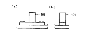
そこで、従来、図8〜図11に示すような支承サイドブロックが提案されている。図8は特別な加工を施さずに曲げ強度設計を行った支承サイドブロック101であり、図9はノッチ102aによって断面縮小部を形成した曲げ強度設計のノッチ型支承サイドブロック102であり、図10は貫通孔103aによって断面縮小部を設けた曲げ強度設計の貫通孔型支承サイドブロック103である。また、図11は支承サイドブロックを設置するセットボルト104aをせん断破壊させるせん断強度設計の支承サイドブロック104である。
背景技術で説明した従来の支承サイドブロックは、ブロック本体の上部を押圧する水平荷重が設計強度に達するといきなり破断する訳ではない。すなわち、想定地震時水平力で降伏が始まりそこから荷重が立ち上がって破断に至るため、設計強度以上の大きな荷重に達してから破断する。そして、支承サイドブロックの破断はこのような大きな荷重が掛かった状態から急激に起きる。このように、プロテクト機能を解除する破断は急激に起きるため、支承サイドブロックが破断した時の衝撃力が上部構造物及び下部構造物に伝わり、この衝撃力によって構造物が損傷する恐れがある。 The conventional support side block described in the background art does not suddenly break when the horizontal load that presses the upper portion of the block body reaches the design strength. That is, since the yield starts with the horizontal force at the time of the assumed earthquake and the load rises and breaks, it breaks after reaching a load larger than the design strength. The breakage of the support side block suddenly occurs from the state where such a large load is applied. As described above, since the break for releasing the protection function occurs abruptly, the impact force when the support side block breaks is transmitted to the upper structure and the lower structure, and the structure may be damaged by the impact force.
本発明は、このような問題点に鑑みてなされたものであり、その目的とするところは、プロテクト機能を解除する破断が急激に起きないようにし、しかも破断時に大きなエネルギー吸収をもつ支承サイドブロックを提供することにある。 The present invention has been made in view of such problems, and the object of the present invention is to prevent the breakage that releases the protection function from occurring suddenly, and to support the side block that has a large energy absorption at the time of the breakage. Is to provide.
本発明の支承サイドブロックは、上部構造物と下部構造物との接合部に設置したゴム支承の両側に配設され、常時はゴム支承が橋軸方向と直交する方向に変形することによる上部構造物の橋軸直角方向の移動を規制するとともに、大規模地震動の際には想定地震時水平力によってプロテクト機能が解除される一体ものの支承サイドブロックであって、地震発生時にゴム支承の上沓により上部が押されるブロック本体と、該ブロック本体の下部左右からそれぞれねじり破断により最終的に分断される接続部位を介して側方に延設され、ブロック本体を下部構造物に立設させる取付部とからなり、下部構造物の保有水平耐力を越えない想定地震時水平力による曲げモーメントの作用により接続部位がねじり破断を開始するように当該接続部位の上下方向断面積を設計したことを特徴とする。 The bearing side block of the present invention is disposed on both sides of the rubber bearing installed at the joint between the upper structure and the lower structure, and the upper structure is formed by constantly deforming the rubber bearing in a direction perpendicular to the bridge axis direction. thereby restricting the movement of the bridge axis perpendicular of the object, the time of large-scale earthquake motion a bearing side blocks although integral Protected functions may be released by the horizontal force at the time assumed earthquake, the shoes on the rubber bearing in the event of an earthquake A block body whose upper part is pushed , and a mounting part which extends laterally from the left and right sides of the lower part of the block body through a connection part that is finally divided by torsional breakage, and causes the block body to stand on the lower structure. from now, on of the connection part so as to initiate the action by breaking the connection site torsional bending moment due to assume earthquake horizontal force held not to exceed the lateral strength of the substructure Wherein the designed direction cross-sectional area.
そして、ブロック本体の上部がゴム支承側に突き出た形状であることが好ましく、またブロック本体の底面が取付部の底面より高くなっていることが好ましい。 And it is preferable that the upper part of a block main body protrudes to the rubber bearing side, and it is preferable that the bottom face of a block main body is higher than the bottom face of an attachment part.
本発明の支承サイドブロックは、上部構造物と下部構造物との接合部に設置したゴム支承の両側に配設され、常時はゴム支承が橋軸方向と直交する方向に変形することによる上部構造物の橋軸直角方向の移動を規制するとともに、大規模地震動の際には想定地震時水平力によってプロテクト機能が解除される一体ものの支承サイドブロックであって、地震発生時にゴム支承の上沓により上部が押されるブロック本体と、該ブロック本体の下部左右からそれぞれねじり破断により最終的に分断される接続部位を介して側方に延設され、ブロック本体を下部構造物に立設させる取付部とからなり、下部構造物の保有水平耐力を越えない想定地震時水平力による曲げモーメントの作用により接続部位がねじり破断を開始するように当該接続部位の上下方向断面積を設計した構成をしているので、降伏が始まってからの荷重の立ち上がりが少なく、接続部位のねじり破断に従って徐々に荷重が低減し、その時の水平変位が大きいため、破断進行時に大きなエネルギー吸収があると同時に、衝撃がなくゴム支承のばねへと水平力が移ることから、急激な破断により衝撃を生じて構造物に損傷を与えるような事態を回避することができる。 The bearing side block of the present invention is disposed on both sides of the rubber bearing installed at the joint between the upper structure and the lower structure, and the upper structure is formed by constantly deforming the rubber bearing in a direction perpendicular to the bridge axis direction. It is an integrated support side block that regulates the movement of objects in the direction perpendicular to the bridge axis and the protection function is canceled by horizontal force during an earthquake when large-scale earthquake motion occurs. A block body whose upper part is pushed , and a mounting part which extends laterally from the left and right sides of the lower part of the block body through a connection part that is finally divided by torsional breakage, and causes the block body to stand on the lower structure. from now, on of the connection part so as to initiate the action by breaking the connection site torsional bending moment due to assume earthquake horizontal force held not to exceed the lateral strength of the substructure Since the structure was designed direction cross-sectional area, breakdown less rise of the load from the beginning, gradually reduce loads in accordance with the torsional breakage of the connection sites, since a large horizontal displacement at that time, large at break progression At the same time as there is energy absorption, there is no impact and the horizontal force moves to the spring of the rubber bearing, so that it is possible to avoid a situation in which an impact is caused by a sudden break and damages the structure.
以下、本発明を実施するための最良の形態を図面に基づいて説明する。 Hereinafter, the best mode for carrying out the present invention will be described with reference to the drawings.
図1は本発明に係る支承サイドブロックをゴム支承の両側に設置した状態をそのゴム支承の一部を破断した状態で示す斜視図、図2は図1を矢印方向から見た状態に対応する側面図、図3は支承サイドブロックを取付状態で示す正面図、図4は支承サイドブロックを取付状態で示す側面図である。 FIG. 1 is a perspective view showing a state in which a support side block according to the present invention is installed on both sides of a rubber support in a state in which a part of the rubber support is broken, and FIG. 2 corresponds to a state in which FIG. 3 is a front view showing the support side block in the mounted state, and FIG. 4 is a side view showing the support side block in the mounted state.
図1及び図2に示すように、支承サイドブロック10は積層ゴム支承20(ゴム支承の一例)の両側に配設されており、常時は積層ゴム支承20が橋軸方向(矢印A方向)と直交する方向に変形することによる上部構造物Saの橋軸直角方向の移動を規制するとともに、大規模地震動の際には想定地震時水平力によってプロテクト機能が解除されるように構成されている。
As shown in FIGS. 1 and 2, the bearing
積層ゴム支承20は、上鋼板21と下鋼板22との間にゴム層23と中間鋼板24とを交互に積層してなるゴム支承本体25と、その上下部にボルトにより固定される上沓26及び下沓27とを備えている。また、上部構造物Saが橋梁における鋼桁の場合には下部フランジにソールプレート28が固定され、下部構造物Sbである橋脚にボルト又は溶接又はアンカーボルトによって下沓27が固定されている。また、ゴム支承本体25と上沓26及び下沓27との間で水平力を伝達するためのせん断キー29,30が設けられている。なお、上部構造物SaがRC桁やPC桁等の場合には、それらに応じた手段によって上部構造物Saに積層ゴム支承20が固定される。
The laminated rubber bearing 20 includes a rubber bearing
支承サイドブロック10は、鋳鋼(例えばSCW480)や鋼材(例えばSM490)などから形成される一体もので、ブロック本体11と該ブロック本体11の下部左右からそれぞれ接続部位12を介して側方に延設された取付部13とからなる。そして、下部構造物Bの保有水平耐力を越えない想定地震時水平力による曲げモーメントの作用により接続部位12がねじり破断を開始するように接続部位12の上下方向断面積を設計している。図示の例では、接続部位12の上下方向の断面を取付部13の上下方向の断面より小さくすることでこれに対応している。また、ブロック本体11の上部を傾斜面を介して積層ゴム支承側に突き出た形状とし、さらにブロック本体11の底面を取付部13の底面より高くしている。
The
支承サイドブロック10の取付部13にはセットボルト14の挿通孔13aが設けられるとともに、積層ゴム支承20の下沓27にはボルト孔が設けられており、セットボルト14を挿通孔13aに挿通してボルト孔に螺合することにより、支承サイドブロック10が積層ゴム支承20の両側に固定されてブロック本体11が立設されている。また、積層ゴム支承20の下沓27には橋軸方向の両サイド付近に2本の浅い溝27aが設けられており、支承サイドブロック10はその取付部13がこの溝27aに嵌まった状態で取り付けられている。
An
地震が発生すると、積層ゴム支承20が弾性変形を起こし、その上沓26が支承サイドブロック10におけるブロック本体11の上部を押すことになる。このように支承サイドブロック10に地震時水平力が作用すると、曲げモーメントによりブロック本体11の外側に圧縮応力が、内側に引張応力がそれぞれ作用する。そして、地震時水平力が道路橋示方書で示すレベル1地震動の地震時水平力を越えると、支承サイドブロック10の接続部位12がねじり破断を開始して図5に示す変形部Nのところでねじり変形を起こし、さらに大きな水平力が加わると、図6に示す如くブロック本体11が取付部13に対して倒れ、一旦倒れだすと徐々に倒れて最終的に変形部Nがねじり破断により分断される。この場合、ブロック本体11の上部が傾斜面を介して積層ゴム支承側に突き出た形状になっているので、ねじり変形が進むにつれても、上沓26によりブロック本体11の上部をスムースに押すことができる。また、ブロック本体11の底面を取付部13の底面より高くしているので、ねじり変形によりブロック本体11の底部が下沓27に当たることがない。
When an earthquake occurs, the laminated rubber bearing 20 is elastically deformed, and the
支承サイドブロック10の接続部位12で起こるねじり破断は、外周部ほど変形量が大きく、ねじり中心ほど変形量が小さい。すなわち、ねじり変形が始まると、まず外周部が破断しその破断が中心部に移行する。このため、破断に抵抗する面積は徐々に減少し、破断を起こさせる力は急激に減少しないで徐々に減少する。また、破断に至るまでのねじりによる変形量も大きくなる。
The torsional break that occurs at the
図7は積層ゴム支承及び支承サイドブロックに作用する水平力Fと水平変位δの理想的な関係を示すグラフである。なお、図中、F軸上のf1 は支承サイドブロックの降伏荷重、f2 は下部構造物の保有水平耐力を示す。 FIG. 7 is a graph showing an ideal relationship between the horizontal force F acting on the laminated rubber bearing and the bearing side block and the horizontal displacement δ. In the figure, f 1 on the F-axis indicates the yield load of the bearing side block, and f 2 indicates the retained horizontal strength of the lower structure.
この図7において、Xは積層ゴム支承20の変位曲線であり、水平力Fが大きくなるにつれて水平変位δも徐々に大きくなる。Yは支承サイドブロック10の変位曲線であり、水平力Fがf1 になるとねじり変形による降伏を開始し、少し立ち上がってから徐々に荷重が低減し、完全に破断して荷重が0になるまで大きく水平方向に変位する。Zは両者を合わせた変位曲線であり、支承サイドブロック10が破断した後、水平力に大きな変化を生じることなくXに移行する。したがって、積層ゴム支承20と支承サイドブロック10に作用する水平力Fと水平変位δとがこのような理想的な関係となるように支承サイドブロック10における接続部位12の上下方向断面積を設計することにより、支承サイドブロック10の破断が急激に起きないようにすることができる。また、支承サイドブロック10の変位曲線Yとδ軸で囲まれる面積が大きいので、その分減衰も大きくなる。
In FIG. 7, X is a displacement curve of the laminated rubber bearing 20, and the horizontal displacement δ gradually increases as the horizontal force F increases. Y is a displacement curve of the bearing
以上、本発明の実施の形態について詳細に説明してきたが、本発明による支承サイドブロックは、上記実施の形態に何ら限定されるものではなく、本発明の趣旨を逸脱しない範囲において種々の変更が可能であることは当然のことである。 As mentioned above, although embodiment of this invention was described in detail, the support side block by this invention is not limited to the said embodiment at all, In the range which does not deviate from the meaning of this invention, various changes are possible. It is natural that it is possible.
例えば、上記の例では、支承サイドブロック10における接続部位12の上部は取付部13の上面より下がっているが、取付部13の上面と面一でも構わない。
For example, in the above example, the upper portion of the
また、上記の例では、積層ゴム支承20の下沓27に支承サイドブロック10の取付部13を嵌め込むための溝27aを設けているが、この溝27aを省略してセットボルト14による固定をしっかりとするようにしてもよい。
In the above example, the
Sa 上部構造物
Sb 下部構造物
10 支承サイドブロック
11 ブロック本体
12 接続部位
13 取付部
13a 挿通孔
14 セットボルト
20 積層ゴム支承
21 上鋼板
22 下鋼板
23 ゴム挿
24 中間鋼板
25 ゴム支承本体
26 上沓
27 下沓
27a 溝
28 ソールプレート
29,30 せん断キー
y1 支承サイドブロックの降伏荷重
y2 下部構造物の保有水平耐力
Sa Upper structure
Claims (3)
Priority Applications (1)
| Application Number | Priority Date | Filing Date | Title |
|---|---|---|---|
| JP2003364330A JP4312026B2 (en) | 2003-10-24 | 2003-10-24 | Support side block |
Applications Claiming Priority (1)
| Application Number | Priority Date | Filing Date | Title |
|---|---|---|---|
| JP2003364330A JP4312026B2 (en) | 2003-10-24 | 2003-10-24 | Support side block |
Publications (2)
| Publication Number | Publication Date |
|---|---|
| JP2005127031A JP2005127031A (en) | 2005-05-19 |
| JP4312026B2 true JP4312026B2 (en) | 2009-08-12 |
Family
ID=34643341
Family Applications (1)
| Application Number | Title | Priority Date | Filing Date |
|---|---|---|---|
| JP2003364330A Expired - Lifetime JP4312026B2 (en) | 2003-10-24 | 2003-10-24 | Support side block |
Country Status (1)
| Country | Link |
|---|---|
| JP (1) | JP4312026B2 (en) |
Families Citing this family (4)
| Publication number | Priority date | Publication date | Assignee | Title |
|---|---|---|---|---|
| JP2007297792A (en) * | 2006-04-28 | 2007-11-15 | Kawaguchi Metal Industries Co Ltd | Locking structure of side block in bridge bearing |
| JP2008133644A (en) * | 2006-11-28 | 2008-06-12 | Kawaguchi Metal Industries Co Ltd | Fixed bearing structure for bridge |
| JP6162457B2 (en) * | 2012-04-04 | 2017-07-12 | 株式会社Ihi | Displacement limiting device |
| JP7116644B2 (en) * | 2018-09-12 | 2022-08-10 | Jr東日本コンサルタンツ株式会社 | Seismic reinforcement method and bridge |
-
2003
- 2003-10-24 JP JP2003364330A patent/JP4312026B2/en not_active Expired - Lifetime
Also Published As
| Publication number | Publication date |
|---|---|
| JP2005127031A (en) | 2005-05-19 |
Similar Documents
| Publication | Publication Date | Title |
|---|---|---|
| KR100635098B1 (en) | Girder bridge protection device using sacrifice means | |
| JP2007239306A (en) | Method of mounting base isolation damper | |
| JP4312026B2 (en) | Support side block | |
| JP3158798U (en) | Integrated device for falling bridge prevention structure and displacement limiting structure | |
| JP4274557B2 (en) | Horizontal load elastic support device | |
| JP4383963B2 (en) | Bolt break type buffer stopper device and bridge seismic isolation device | |
| CN111364506A (en) | Self-resetting anti-seismic energy-consumption split column | |
| JP6936114B2 (en) | Seismic isolation structure damper mechanism, seismic isolation structure damper mechanism layout structure, seismic isolation structure trigger mechanism, seismic isolation structure trigger mechanism layout structure, seismic isolation structure sliding bearing mechanism, and building | |
| JP2020153063A (en) | Bearing structure with damage control function for bridge | |
| JP6352845B2 (en) | V brace fulcrum structure | |
| JP3800476B2 (en) | Earthquake resistant building | |
| JP2019031827A (en) | Function separation type shock absorber and bridge provided with function separation type shock absorber | |
| JP4547979B2 (en) | Vibration control pillar | |
| JP4581729B2 (en) | Calculation method of shear stress of reinforced concrete beam, design method of reinforced concrete beam, reinforced concrete beam | |
| JPH09302621A (en) | Low noise type base isolation stacked rubber bearing | |
| JP2009068295A (en) | Elevated structure | |
| CN218345934U (en) | Variable-rigidity limiting anti-beam-falling device | |
| JP4456726B2 (en) | Seismic isolation structure | |
| KR100964299B1 (en) | Lead Rubber Bearing | |
| US20240020431A1 (en) | Connection design method for lateral resisting system of self-centering steel frame | |
| JP6850626B2 (en) | Tsunami bearing bridge support device that exceeds the setting | |
| JP7231940B2 (en) | Rubber bearings for bridges | |
| JP4588909B2 (en) | Anti-vibration control structure | |
| JP3960491B2 (en) | Shock absorber | |
| JPH10266128A (en) | Bridge pier structure of highway bridge |
Legal Events
| Date | Code | Title | Description |
|---|---|---|---|
| A621 | Written request for application examination |
Free format text: JAPANESE INTERMEDIATE CODE: A621 Effective date: 20060828 |
|
| A977 | Report on retrieval |
Free format text: JAPANESE INTERMEDIATE CODE: A971007 Effective date: 20090210 |
|
| A131 | Notification of reasons for refusal |
Free format text: JAPANESE INTERMEDIATE CODE: A131 Effective date: 20090407 |
|
| A521 | Request for written amendment filed |
Free format text: JAPANESE INTERMEDIATE CODE: A523 Effective date: 20090409 |
|
| TRDD | Decision of grant or rejection written | ||
| A01 | Written decision to grant a patent or to grant a registration (utility model) |
Free format text: JAPANESE INTERMEDIATE CODE: A01 Effective date: 20090501 |
|
| A01 | Written decision to grant a patent or to grant a registration (utility model) |
Free format text: JAPANESE INTERMEDIATE CODE: A01 |
|
| A61 | First payment of annual fees (during grant procedure) |
Free format text: JAPANESE INTERMEDIATE CODE: A61 Effective date: 20090512 |
|
| FPAY | Renewal fee payment (event date is renewal date of database) |
Free format text: PAYMENT UNTIL: 20120522 Year of fee payment: 3 |
|
| R150 | Certificate of patent or registration of utility model |
Ref document number: 4312026 Country of ref document: JP Free format text: JAPANESE INTERMEDIATE CODE: R150 Free format text: JAPANESE INTERMEDIATE CODE: R150 |
|
| FPAY | Renewal fee payment (event date is renewal date of database) |
Free format text: PAYMENT UNTIL: 20120522 Year of fee payment: 3 |
|
| S111 | Request for change of ownership or part of ownership |
Free format text: JAPANESE INTERMEDIATE CODE: R313111 |
|
| FPAY | Renewal fee payment (event date is renewal date of database) |
Free format text: PAYMENT UNTIL: 20120522 Year of fee payment: 3 |
|
| R350 | Written notification of registration of transfer |
Free format text: JAPANESE INTERMEDIATE CODE: R350 |
|
| FPAY | Renewal fee payment (event date is renewal date of database) |
Free format text: PAYMENT UNTIL: 20150522 Year of fee payment: 6 |
|
| R250 | Receipt of annual fees |
Free format text: JAPANESE INTERMEDIATE CODE: R250 |
|
| R250 | Receipt of annual fees |
Free format text: JAPANESE INTERMEDIATE CODE: R250 |
|
| R250 | Receipt of annual fees |
Free format text: JAPANESE INTERMEDIATE CODE: R250 |
|
| R250 | Receipt of annual fees |
Free format text: JAPANESE INTERMEDIATE CODE: R250 |
|
| R250 | Receipt of annual fees |
Free format text: JAPANESE INTERMEDIATE CODE: R250 |
|
| R250 | Receipt of annual fees |
Free format text: JAPANESE INTERMEDIATE CODE: R250 |
|
| R250 | Receipt of annual fees |
Free format text: JAPANESE INTERMEDIATE CODE: R250 |
|
| R250 | Receipt of annual fees |
Free format text: JAPANESE INTERMEDIATE CODE: R250 |
|
| R250 | Receipt of annual fees |
Free format text: JAPANESE INTERMEDIATE CODE: R250 |
|
| EXPY | Cancellation because of completion of term |