JP4310198B2 - Image forming apparatus - Google Patents
Image forming apparatus Download PDFInfo
- Publication number
- JP4310198B2 JP4310198B2 JP2004006883A JP2004006883A JP4310198B2 JP 4310198 B2 JP4310198 B2 JP 4310198B2 JP 2004006883 A JP2004006883 A JP 2004006883A JP 2004006883 A JP2004006883 A JP 2004006883A JP 4310198 B2 JP4310198 B2 JP 4310198B2
- Authority
- JP
- Japan
- Prior art keywords
- toner
- developer
- image forming
- environment
- forming apparatus
- Prior art date
- Legal status (The legal status is an assumption and is not a legal conclusion. Google has not performed a legal analysis and makes no representation as to the accuracy of the status listed.)
- Expired - Fee Related
Links
Images


Classifications
-
- G—PHYSICS
- G03—PHOTOGRAPHY; CINEMATOGRAPHY; ANALOGOUS TECHNIQUES USING WAVES OTHER THAN OPTICAL WAVES; ELECTROGRAPHY; HOLOGRAPHY
- G03G—ELECTROGRAPHY; ELECTROPHOTOGRAPHY; MAGNETOGRAPHY
- G03G15/00—Apparatus for electrographic processes using a charge pattern
- G03G15/06—Apparatus for electrographic processes using a charge pattern for developing
- G03G15/08—Apparatus for electrographic processes using a charge pattern for developing using a solid developer, e.g. powder developer
- G03G15/0822—Arrangements for preparing, mixing, supplying or dispensing developer
- G03G15/0844—Arrangements for purging used developer from the developing unit
Description
本発明は、一般には、電子写真方式又は静電記録方式により像担持体に静電潜像を形成し、この静電潜像を現像装置に収容した現像剤にて顕像化する画像形成装置に関し、特に非画像形成時に現像剤を電子写真感光体に転移させる動作を行う画像形成装置に関する。 The present invention generally forms an electrostatic latent image on an image carrier by an electrophotographic method or an electrostatic recording method, and visualizes the electrostatic latent image with a developer contained in a developing device. In particular, the present invention relates to an image forming apparatus that performs an operation of transferring a developer to an electrophotographic photosensitive member during non-image formation.
従来の画像形成装置、例えば電子写真方式による画像形成装置においては、ドラム状の電子写真感光体(感光ドラム)表面を帯電装置によって一様に帯電し、帯電された感光ドラム表面を露光装置によって露光して静電潜像を形成し、この静電潜像を現像装置で現像して現像剤(トナー)像を形成し、このトナー像を転写装置によって用紙などの転写材に転写して、定着装置によりトナー像を転写材上に永久固着画像として定着して出力する画像形成工程が実施されている。画像形成工程において、トナー像転写後に感光ドラム表面に残留したトナーは、クリーニング装置によってクリーニングされ、次の画像形成動作に備える。 In a conventional image forming apparatus, for example, an electrophotographic image forming apparatus, the surface of a drum-shaped electrophotographic photosensitive member (photosensitive drum) is uniformly charged by a charging device, and the charged photosensitive drum surface is exposed by an exposure device. Then, an electrostatic latent image is formed, and the electrostatic latent image is developed by a developing device to form a developer (toner) image. The toner image is transferred to a transfer material such as paper by a transfer device, and then fixed. An image forming process for fixing and outputting a toner image as a permanently fixed image on a transfer material by an apparatus is performed. In the image forming process, the toner remaining on the surface of the photosensitive drum after the transfer of the toner image is cleaned by a cleaning device to prepare for the next image forming operation.
このような画像形成装置が実施する画像形成工程のうち現像工程において、現像装置が単位時間に現像できる面積が少ないものを用いる場合、即ち画像の面積率が低い場合等には、長時間の現像駆動が行われるが、その際に、トナーの劣化現象が生じる。例えば、現像に共されているトナーは形状が不規則になったり、粒径の分布に偏りを生じたりし、トナーの流動性向上及びトナーの摩擦帯電性を安定させるために添加されているシリカ等の外添剤がトナー表面に埋め込まれてしまい、帯電能力が低下し、又、現像性が低下する。そして、トナーの現像性低下に伴う濃度低下やトナーの摩擦帯電能力の低下に伴うかぶりが発生するという問題が生じる。 Of the image forming processes carried out by such an image forming apparatus, in the developing process, when a developing apparatus having a small area that can be developed per unit time is used, that is, when the area ratio of the image is low, etc. Driving is performed, but at this time, a toner deterioration phenomenon occurs. For example, the toner used for development becomes irregular in shape or has an uneven particle size distribution, and is added to improve toner fluidity and stabilize toner triboelectric chargeability. Such an external additive is embedded in the toner surface, the charging ability is lowered, and the developability is also lowered. Further, there arises a problem that fogging occurs due to a decrease in density associated with a decrease in toner developability and a decrease in frictional charging ability of the toner.
又、従来公知の一成分現像装置においては、上記理由で長時間の現像駆動が行われた場合、現像装置に備えられた周面にトナーを担持して回転して感光ドラムへとトナーを搬送する現像剤担持体上の未現像トナーが現像剤担持体上のトナー層厚を規制する現像ブレードで何回も摩擦されるために上記不具合に加え、現像ブレードへのトナー固着が発生するという問題もある。 Also, in the conventional one-component developing device, when the development driving is performed for a long time for the above reason, the toner is carried on the peripheral surface provided in the developing device and rotated to convey the toner to the photosensitive drum. In addition to the above problems, unfixed toner on the developer carrying member is rubbed many times by the developing blade that regulates the toner layer thickness on the developer carrying member, and toner sticking to the developing blade occurs. There is also.
このような問題に対しては種々の提案がなされている。 Various proposals have been made for such problems.
例えば、トナー劣化に起因する濃度低下やかぶり対策、又現像ブレードへのトナー固着対策として、特許文献1に開示の画像形成装置は、検知手段により検知された現像剤の消費量に関係する特定の検出値に基づいて、現像剤保持体上の現像剤を像担持体上の非画像形成領域で強制的に消費し、適宜現像剤保持体から除去することにより、現像剤保持体への静電吸着力が極端に強くなることが無く、安定した画像を形成するようにしている。
For example, the image forming apparatus disclosed in
又、特許文献2に開示の現像装置は、黒画素カウンタと枚数カウンタに基づいて1枚平均の黒字面積率を算出し、黒字面積率が所定の値に達するようにページ間において像書き込みさせることで、トナー規制手段へのトナー固着を防止し、かつ地肌汚れ等の異常画像を防止するようにしている。
Further, the developing device disclosed in
又、特許文献3に開示の画像形成装置では、用紙への画像形成を行う頻度に応じた所定のタイミングで強制現像して、現像ローラに付着している劣化トナーを定期的に除去することによりカブリ現象を緩和し、印字品質の低下を防止するようにしている。
Further, the image forming apparatus disclosed in
そして、トナーの形状や状態変化や外添剤のトナーへの埋没等のトナー劣化対策として、トナー補給を好適に行う方法があり、特許文献4に開示の画像形成装置では、現像剤収容部内のトナー消費及び補給がない状態で、現像剤の撹拌が所定時間以上行われるときに、トナー強制消費とともに現像剤収容部内にトナーを強制補給することで、現像剤の撹拌摩擦による劣化を抑制するようにしている。
As a countermeasure against toner deterioration such as a change in the shape and state of the toner and the embedding of an external additive in the toner, there is a method of suitably supplying toner. In the image forming apparatus disclosed in
又、特許文献5に開示の画像形成装置では、入力された画像データにより1枚ごとの画像比率を計算し、画像比率が所定値以下の場合には、感光体ドラムに対してトナー消費を行うとともに相当量のトナー補給も行うことで、トナー消費量が少ない画像を連続出力した場合でも、濃度低下等の画質の劣化を防止するようにしている。
In the image forming apparatus disclosed in
更に、現像時間が長時間になるのを回避する対策もあり、特許文献6に開示の画像形成装置では、現像装置の駆動時間をカウントし、駆動時間に応じて非画像部において強制書き込みを実施するようにしたので、潜像における画像面積比率が低い場合でも、現像剤エンドまでの現像駆動時間をねらいの時間以内にすることが可能となり、新たに現像剤を現像装置内に補給した後での地肌汚れを防止している。このように非画像形成時に所定のタイミングにおいて、強制的にトナーを現像装置から感光ドラムに対してトナーを転移させることによって現像装置内の劣化したトナーを消費することで現像装置内のトナーを初期化する。
Furthermore, there is a measure to avoid a long development time. In the image forming apparatus disclosed in
そして感光ドラム上に転移させたトナーは特許文献3や特許文献4に開示されているようにクリーニング装置によって感光ドラム上から掻き落とされクリーニングされる。
The toner transferred onto the photosensitive drum is scraped off from the photosensitive drum and cleaned by a cleaning device as disclosed in
このような、現像装置内の劣化したトナーを消費することで現像装置内のトナーを初期化させる方法は好適に実施されているが、現像装置から感光ドラムに対して強制的に転移させるトナー量の決定方法としては、効果的に初期化させるためには、現像装置内で劣化したトナー量に相当させることが好ましく、具体的には、現像剤担持体の1周分相当以上とすることが良い。更に、現像剤担持体に当接しトナーを現像剤担持体に搬送・供給するトナー供給部材を兼ね備えた現像装置においては、現像剤担持体の1周分又はトナー供給部材の1周分の多い方の部材の1周分相当以上とすることが良い。 Such a method for initializing the toner in the developing device by consuming the deteriorated toner in the developing device is suitably implemented, but the amount of toner to be forcibly transferred from the developing device to the photosensitive drum As a determination method, it is preferable to correspond to the amount of toner deteriorated in the developing device in order to effectively initialize, and specifically, it is equivalent to one or more times of the developer carrier. good. Further, in a developing device that also has a toner supply member that abuts the developer carrier and conveys and supplies toner to the developer carrier, the larger of one developer carrier or one toner supply member It is preferable to make it equal to or more than one round of the member.
しかしながら、上記構成の画像形成装置においては、効果的に現像装置内の劣化トナーを現像装置から感光ドラムに対して強制的に転移させるためには、相当量のトナーを転移させる必要があり、前記したように現像装置内に設けられた各部材の1周分以上に相当するトナー量を転移させる必要があった。 However, in the image forming apparatus having the above configuration, in order to effectively transfer the deteriorated toner in the developing device from the developing device to the photosensitive drum, it is necessary to transfer a considerable amount of toner. As described above, it is necessary to transfer the toner amount corresponding to one or more rounds of each member provided in the developing device.
そして、この制御は非画像形成時に実施されるため、感光ドラムに転移したトナーは転写材等に転写されることなくクリーニング装置に回収される。クリーニング装置に回収されるトナー量は、画像形成時においては転写材に転写されずに感光ドラム上に残ったトナー量(転写残トナー)に比較し、強制的に感光ドラム上に転移させたトナー量は非常に多くなるため、クリーニング装置への負荷が増えてしまうが、いわゆる常温常湿環境、例えば温度が15℃〜25℃、湿度が30%RH〜60%RHの環境においてクリーニング不良が発生することはなかった。 Since this control is performed at the time of non-image formation, the toner transferred to the photosensitive drum is collected by the cleaning device without being transferred to a transfer material or the like. The amount of toner collected by the cleaning device is forcibly transferred to the photosensitive drum compared with the amount of toner remaining on the photosensitive drum (transfer residual toner) that is not transferred to the transfer material during image formation. Although the amount increases, the load on the cleaning device increases. However, defective cleaning occurs in a so-called room temperature and normal humidity environment, for example, a temperature of 15 ° C. to 25 ° C. and a humidity of 30% RH to 60% RH. I never did.
しかしながら、クリーニング装置として従来公知のウレタンゴム、シリコーンゴム等の弾性体ブレードから構成されるクリーニングブレードを用いたクリーニング装置の場合、低温環境又は低湿環境下においては、弾性体の反発弾性率が低下してしまい、クリーニングブレード当接部での感光ドラム駆動によるわずかな位置変動に対して追従して当接できなくなりクリーニング不良が一層悪化してしまうという問題があった。
本発明の目的は、非画像形成時に、現像装置から像担持体に転移させて、劣化トナーを現像装置から吐き出す画像形成装置において、低温又は低湿環境下におけるクリーニング不良の発生を防止し、トナー劣化に伴うかぶりや濃度低下のない良好な画質を得ることができる画像形成装置を提供することである。 An object of the present invention is to prevent occurrence of poor cleaning in a low-temperature or low-humidity environment in an image forming apparatus that transfers a deteriorated toner from a developing apparatus by transferring from a developing apparatus to an image carrier during non-image formation. It is an object of the present invention to provide an image forming apparatus capable of obtaining a good image quality without fogging and density reduction accompanying the above.
上記目的は本発明に係る画像形成装置にて達成される。要約すれば、本発明は、像担持体と、
該像担持体表面を露光することによって静電潜像を形成する露光装置と、
現像剤を収容して前記静電潜像を現像する現像装置と、
クリーニングブレードによって前記像担持体上の現像剤を除去するクリーニング装置と、
画像形成装置内部の温度と湿度を検知する環境検知手段と、
非画像形成時に、所定のタイミングにて、前記露光装置により前記像担持体を露光し、形成された潜像部分に前記現像装置により所定量の現像剤を転移させるよう構成され、1回の前記現像装置からの前記像担持体への現像剤転移量を前記環境検知手段の検知結果に応じて決定する現像剤転移制御手段と、
を有する画像形成装置において、
前記現像剤転移量は、
所定温度を超えかつ所定湿度以下の環境の時の方が、前記所定温度を超えかつ前記所定湿度を超えた環境の時のよりも少なく、
前記所定温度未満の環境の時の方が、前記所定温度を超えかつ前記所定湿度以下の環境の時よりも少ない、
ことを特徴とする画像形成装置を提供する。
The above object is achieved by the image forming apparatus according to the present invention. In summary, the present invention comprises an image carrier,
An exposure device that forms an electrostatic latent image by exposing the surface of the image carrier;
A developing device that contains a developer and develops the electrostatic latent image ;
A cleaning device for removing the developer on the image carrier by a cleaning blade;
Environmental detection means for detecting the temperature and humidity inside the image forming apparatus;
During non-image formation, at a predetermined timing, the image bearing member is exposed by the exposure device, it is configured to transfer a predetermined amount of the developer by the developing device formed latent image portion, one of the Developer transfer control means for determining a developer transfer amount from the developing device to the image carrier according to a detection result of the environment detection means ;
In an image forming apparatus having
The developer transfer amount is
When the environment is above the predetermined temperature and below the predetermined humidity, it is less than the environment above the predetermined temperature and above the predetermined humidity.
When the environment is less than the predetermined temperature, the environment is less than when the environment is above the predetermined temperature and below the predetermined humidity.
An image forming apparatus is provided.
本発明の一実施態様によると、前記現像装置は、現像剤を周面に担持して回転し、前記像担持体へと現像剤を搬送する現像剤担持体を備え、前記現像剤転移制御手段は、前記所定温度を超えかつ前記所定湿度を超えた環境における前記現像剤転移量を、前記現像剤担持体の1周分にて担持される相当量より多くするか、又は、前記現像装置は、現像剤を周面に担持して回転し、前記像担持体へと現像剤を搬送する現像剤担持体と、該現像剤担持体に当接して、現像剤を前記現像剤担持体へ供給する現像剤供給部材と、を備え、前記現像剤転移制御手段は、前記所定温度を超えかつ前記所定湿度を超えた環境における前記現像剤転移量を、前記現像剤担持体又は前記現像剤供給部材の1周分にて担持される相当量より多くする。 According to an embodiment of the present invention, the developing device includes a developer carrier that carries a developer on a peripheral surface thereof, rotates, and conveys the developer to the image carrier, and the developer transfer control unit. , the exceeds the predetermined temperature and the developer transferred amount at environment exceeds the predetermined humidity, the developer carrier of the multi-camphor Luke than equivalent amount carried by one turn, or the developing device Comprises a developer carried on a peripheral surface and rotated to convey the developer to the image carrier, and a developer carrier in contact with the developer carrier, and the developer to the developer carrier. A developer supply member for supplying the developer transfer control means, wherein the developer transfer control means determines the developer transfer amount in an environment that exceeds the predetermined temperature and exceeds the predetermined humidity as the developer carrier or the developer supply. multi than equivalent amount carried in one round of the member Ru camphor.
本発明の他の実施態様によると、前記現像剤転移制御手段は、前記露光装置による前記像担持体における露光面積を変更させることによって、前記現像剤転移量を制御するか、又は、前記現像装置は前記現像剤担持体に現像電圧を印加する現像高圧電源を備え、前記現像剤転移制御手段は、前記現像高圧電源による前記現像電圧を変更することで、前記現像剤転移量を制御する。 According to another embodiment of the present invention, the developer transfer control means controls the developer transfer amount by changing an exposure area of the image carrier by the exposure device, or the developing device. is provided with a development high-voltage power supply for applying a developing voltage to said developer carrying member, said developer transition control means, by changing the developing voltage by the development high-voltage power supply, for controlling the developer transfer amount.
本発明の他の実施態様によると、前記現像剤転移制御手段は、前記所定温度未満の環境においては、前記露光装置による露光は行わないモードを実行するか、又は、前記現像剤転移制御手段は、前記所定温度未満の環境においては、前記露光装置による露光は行わずかつ現像装置の駆動を停止するモードを実行する。 According to another embodiment of the present invention, the developer transfer control means executes a mode in which exposure by the exposure apparatus is not performed in an environment below the predetermined temperature, or the developer transfer control means In an environment below the predetermined temperature, a mode is executed in which exposure by the exposure apparatus is not performed and driving of the developing apparatus is stopped.
本発明の他の実施態様によると、前記所定のタイミングは、前記画像形成装置で画像形成を行った回数又は前記現像装置の稼働時間により決定される。 According to another embodiment of the present invention, the predetermined timing, the also number of times of image formation in the image forming apparatus is determined by the operation time of the developing device.
本発明の画像形成装置は、1回の現像装置からの像担持体への現像剤転移量は、所定温度を超えかつ所定湿度以下の環境の時の方が、前記所定温度を超えかつ前記所定湿度を超えた環境の時のよりも少なく、前記所定温度未満の環境の時の方が、前記所定温度を超えかつ前記所定湿度以下の環境の時よりも少ない、構成とされるので、画像形成装置内部の環境に応じて、強制的に像担持体に対して転移させる劣化トナー量が変更され、それによって、現像性を損なうことなく、クリーニングブレードの良好なクリーニング性を維持することが可能となった。 In the image forming apparatus of the present invention, the amount of developer transferred from the developing device to the image carrier once exceeds the predetermined temperature and exceeds the predetermined temperature in an environment of a predetermined humidity or lower. Since the configuration is such that it is less when the environment is less than the predetermined temperature and less than the predetermined temperature than when the environment is above the predetermined temperature and less than the predetermined temperature and below the predetermined humidity. The amount of deteriorated toner that is forcibly transferred to the image carrier is changed according to the environment inside the apparatus , and it is thereby possible to maintain good cleaning performance of the cleaning blade without impairing developability. became.
以下、本発明に係る画像形成装置を図面に則して更に詳しく説明する。 The image forming apparatus according to the present invention will be described below in more detail with reference to the drawings.
実施例1
本発明に係る画像形成装置の実施例1を図1〜図4によって詳しく説明する。本実施例の画像形成装置は、ホストコンピュータからの画像情報を受け取り、画像出力するプリンタであり像担持体である感光ドラム、現像剤(トナー)等の消耗品をプロセスカートリッジとして、本体から着脱し交換可能に設けた画像形成装置である。
Example 1
図1は、本実施例で用いた画像形成装置の概略構成図である。図1に示すように、本実施例の画像形成装置においては、ユーザの所望の画像を形成する通常画像形成工程において、像担持体である感光ドラム2は矢印A方向に回転駆動され、帯電工程にて帯電ローラにて構成される一次帯電器3によって均一に帯電される。本実施例では感光ドラム2の周速度を94.2mm/secとし、一次帯電器3で均一帯電された感光ドラム2の暗部表面電位Vdを本実施例ではVd=−500Vとした。
FIG. 1 is a schematic configuration diagram of an image forming apparatus used in this embodiment. As shown in FIG. 1, in the image forming apparatus of this embodiment, in a normal image forming process for forming a user's desired image, the
そして、潜像形成工程、本実施例は電子写真方式であるので、露光工程にて、露光装置であるレーザ、ポリゴンミラー、レンズ系を含むスキャナユニット1から画像信号に応じて変調されたレーザ光Lがスキャン出力され、このレーザ光Lは折り返しミラー11で反射して感光ドラム2上に照射される。−500Vに一様帯電されている感光ドラム2表面において、レーザ光Lが照射された露光部にて帯電電位が変更されて静電潜像が形成され、本実施例ではこの明部表面電位VlをVl=−100Vとした。
Since the latent image forming step, which is an electrophotographic method in this embodiment, the laser beam modulated in accordance with the image signal from the
感光ドラム2表面に形成された静電潜像は、現像工程にて、矢印B方向に回転駆動される現像装置4に設けられた現像剤担持体である現像ローラ42によって、担持、搬送されたトナー41を、不図示の現像高圧電源から印加された現像電圧(現像バイアス)により感光ドラム2表面の静電潜像部分に移動させることで、現像し感光ドラム2上に現像剤像(トナー像)として顕像化される。本実施例では、現像バイアス電圧VdcをVdc=−300Vとし負帯電性のトナー41を反転現像することで感光ドラム2上にトナー41による顕画像を形成した。
The electrostatic latent image formed on the surface of the
一方、カセット71内に収納された転写材7は、給紙ローラ72によって感光ドラム2での潜像の形成と同期してレジストローラ73まで供給される。そして、この転写材7は、転写工程にて、レジストローラ73によって、感光ドラム2上に形成された潜像の先端と同期して、転写ローラとして構成される転写帯電器6に搬送され、転写帯電器6によって感光ドラム2表面に形成されているトナー像が該転写材7に転写される。本実施例では転写帯電器6に不図示の転写高圧電源から転写バイアス電圧VtrとしてVtr=1000Vを印加し転写工程を行った。
On the other hand, the
トナー像を転写された転写材7は、定着工程にて、定着器8によってトナー像を永久定着された後、最後に装置外部に排出される。
The
尚、感光ドラム2上に残留した現像剤(トナー)は弾性ブレードにて構成されるクリーニング部材(クリーニングブレード)51を用いたクリーニング装置5によって除去される。クリーニングブレード51は弾性ブレード先端が感光ドラム2の回転方向Aに対しカウンタ方向となるように配置される。
The developer (toner) remaining on the
ここで、本実施例に用いたクリーニングブレード51の断面図を図2に示す。金属板金を材料として形成されたホルダー51aにウレタンゴム等のゴム弾性体を材料として形成された弾性ブレード51bを接着させ、クリーニングブレード51とした。弾性ブレード51bとしては、本実施例で用いたウレタンゴムの他シリコーンゴム、ニトリルゴム、クロロプレンゴム等の弾性体を用いることも可能である。
Here, FIG. 2 shows a sectional view of the
つまり、本実施例の画像形成装置にて、長時間現像による現像装置4内の劣化トナーが引き起こす問題への対策として、非画像形成時に現像装置4から感光ドラム2に対して強制的に転移させ、現像装置4内の劣化したトナーを消費することで現像装置4内のトナーを初期化させる現像剤転移制御手段を設けた場合、従来例にて生じたような、クリーニング不良が発生しやすい構成のクリーニングブレード51を使用している。
That is, in the image forming apparatus of this embodiment, as a countermeasure against the problem caused by the deteriorated toner in the developing
そこで、本発明にては、画像形成装置内部の環境に応じて強制的に感光ドラム2に対して転移させる劣化トナー量を変更することで、現像性を損なうことなく、クリーニングブレード51の良好なクリーニング性を維持することができるようにした。
Therefore, in the present invention, by changing the amount of deteriorated toner that is forcibly transferred to the
即ち、本発明の画像形成装置は環境に応じた制御を実行するために、環境検知手段が設けられているが、環境検知手段(環境検知センサ)12は、画像形成装置内部の温度や湿度を計測するために、装置本体内部に備えられ、本実施例ではクリーニング装置5近傍に配置した。
That is, the image forming apparatus of the present invention is provided with environment detecting means for executing control according to the environment, but the environment detecting means (environment detecting sensor) 12 controls the temperature and humidity inside the image forming apparatus. In order to perform measurement, it is provided inside the apparatus main body, and in the present embodiment, it is disposed in the vicinity of the
又、本実施例では、感光ドラム2、帯電ローラ3、現像装置4、クリーニング装置5を一括してユニット化して、プロセスカートリッジ10を構成しており、これらの構成要素はカートリッジ10内で所定の相互配置関係を持って組み付けられており、カートリッジ10は画像形成装置本体内の所定部に対して所定の要領で挿入装着され、又、反対に装置本体から抜き外しできるようになっているので、メンテナンス性がある。
In this embodiment, the
ここで、本実施例の特徴部分である、非画像形成時に、現像装置4から感光ドラム2に対して強制的に転移させ、現像装置4内の劣化したトナーを消費して新しいトナーを補給可能とすることで現像装置4内のトナーを初期化させる制御について説明する。
Here, at the time of non-image formation, which is a characteristic part of the present embodiment, it is possible to forcibly transfer from the developing
まず、図3を用いて、本実施例の現像装置4を説明する。図3は本実施例の現像装置4であり、トナー容器40内に収納された現像剤(トナー)41と、トナー41を外周面に担持し、感光ドラム2と形成される現像領域に搬送する現像ローラ42と、トナー41を現像ローラ42に搬送及び塗布する現像剤供給部材であるトナー供給ローラ43と、トナー供給ローラ43により塗布されたトナー41を現像ローラ42上に適切な量で担持されるようトナー量を規制する層厚規制部材である現像ブレード44と、現像領域から現像ローラ42回転方向下流側で現像ローラ42に接触し現像装置4内部からのトナー漏れを防止する吹き出し防止シート45と、現像領域にて現像工程を行うために現像ローラ42に接続され、画像形成装置本体内部に備えられた現像高圧電源46にて現像装置4は構成されている。
First, the developing
現像ローラ42は、アルミニウム、その合金、ステンレス等の金属の円筒体42aの周囲に、基層とその上の表層とで構成される弾性層42bを設けて構成されており、本実施例では外径16mmとした。弾性層42bの基層はシリコーンゴム、ポリウレタンゴム、NBR等のゴムで構成され、表層はエーテルウレタンやナイロン等から構成されている。もちろんこれらに限定されるものではなく、基層にスポンジ等の発泡体を用い、表層にゴム弾性層を形成した構造も可能である。又、本実施例において、現像ローラ42は、弾性層42bとしてポリウレタンゴムを用い、周速度141mm/secで矢印B方向に回転駆動される。
The developing
現像ブレード44は、金属薄板としてのバネ弾性を有する厚さ0.1mmのリン青銅板に、厚さ1mmのポリアミドエラストマー弾性部材を接着し、もしくは射出成形して形成され、弾性部材面を現像ローラ42の表面に対して所定の線圧で当接している。金属薄板により現像ローラ42に対する現像ブレード44の圧接力を維持し、ポリアミドエラストマーにより負帯電性のトナー41に対する帯電性を持たせ、且つ、現像ローラ42上に所定厚のトナー層を形成するものである。本実施例では、現像ブレード44通過後の現像ローラ42に担持されるトナー量が0.4mg/cm2となるように現像ブレード44を設定した。金属薄板は現像ブレード44の圧接力を維持するものであれば特に限定されず、又、弾性部材もトナーの帯電性を考慮して選択可能である。又、使用されるトナー41や現像ローラ42の組合わせによってはステンレス薄板、リン青銅薄板等のバネ弾性を有する金属薄板をそのまま用いてトナー41を介して現像ローラ42に当接する構成の現像ブレード44を用いても構わない。
The developing
トナー供給ローラ43は、スポンジ構造や芯金上にレーヨン、ナイロンなどの繊維を植毛したファーブラシ構造のものが、現像ローラ42に対するトナーの搬送・塗布および現像残りのトナーの剥ぎ取りの点から好ましく、本実施例では、金属芯金43a上にウレタンフォーム43bを設け、直径16mmの弾性ローラとして用いた。この弾性ローラで構成されるトナー供給ローラ43は、現像ローラ42に所定の侵入量で当接して、現像ローラ42と同一方向(矢印C方向)で周速度113mm/secで回転駆動され、その駆動タイミングは、現像ローラ42と同期しながら駆動・停止される。本実施例では、トナー供給ローラ43の現像ローラ42に対する侵入量を1.5mmとした。
The
次に、現像装置4内のトナーを初期化させるために、現像装置4から感光ドラム2に対して強制的に転移させる構成を、本実施例の画像形成装置の概略関係図である図4を用いて説明する。
Next, in order to initialize the toner in the developing
非画像形成時に、所定タイミングにて現像装置4から感光ドラム2へとトナー41を転移させる現像剤転移制御は、画像形成装置の動作全体を制御する制御手段21が、現像剤転移制御手段として主に行う。制御手段21は、スキャナユニット1、現像装置4、転写帯電器6などに接続しており、不図示のホストコンピュータ等から入力された画像情報に基づいて、転写材7に画像形成を行うための制御を行うものである。
In the developer transfer control for transferring the
ここで、上記に説明したような、帯電工程、潜像形成工程、現像工程、転写工程、定着工程を含む、上記のユーザの所望の通常の画像を形成する画像形成工程がなされるモードを通常画像形成モードと称す。 Here, the mode in which the image forming process for forming the normal image desired by the user is performed, including the charging process, the latent image forming process, the developing process, the transfer process, and the fixing process, as described above, is usually performed. This is referred to as an image forming mode.
制御手段21には、画像形成回数つまり印刷枚数をカウントする枚数カウンタ20が接続される。枚数カウンタ20は、通常画像形成モードで画像出力した転写材の枚数をカウントするものである。制御手段21は、枚数カウンタ20の値を読み込み、所定枚数に達すると現像装置4から感光ドラム2に対して強制的にトナーを転移させる動作を実施させる。この動作を強制モードとする。
Connected to the control means 21 is a
本実施例では100枚毎に強制モードを実施させた。そして強制モードを実行するたびに枚数カウンタ20のカウント値をリセットして、通常画像形成モード実行枚数を再び積算する構成としている。
In this embodiment, the forced mode is performed every 100 sheets. Each time the forced mode is executed, the count value of the
強制モードの具体的な動作を説明すると、まず、制御手段21では通常画像形成モードを一時中断し、転写材7の搬送を停止させ、つまり、非画像形成時の状態として、スキャナユニット1から主走査方向全域でかつ副走査方向に所定幅の露光を実施し、ホストコンピュータ等から入力された画像情報とは異なる潜像を形成する。
The specific operation in the forced mode will be described. First, the
尚、このような画像形成装置において、レーザービームが走査される方向つまり転写材搬送方向と交差する方向を主走査方向、感光ドラム2や転写帯電器6が移動する方向を副走査方向と称す。
In such an image forming apparatus, the direction in which the laser beam is scanned, that is, the direction intersecting the transfer material conveyance direction is referred to as the main scanning direction, and the direction in which the
次に、現像装置4には現像バイアス電圧が印加され現像装置4内のトナー41が、感光ドラム2上に形成されたホストコンピュータ等から入力された画像情報とは異なる潜像に転移され、現像装置4内のトナーは初期化される。
Next, a developing bias voltage is applied to the developing
次に、感光ドラム2に転移したトナー41は感光ドラム2の回転に伴ってクリーニング装置5に回収されるが、この際、転写帯電器6を転写材7を介さずにトナー41が通過するので転写帯電器6の汚れを防止するため転写バイアス電圧VtrをVtr=0Vに設定した。ここまでの動作を、100枚に1回行う。この動作が強制モードである。
Next, the
本実施例では、強制モードにおける潜像形成において、スキャナユニット1の主走査方向全域の走査幅を216mmとした。又、強制モードにおけるスキャナユニット1の副走査方向の露光幅は、現像ローラ42又はトナー供給ローラ43の1周分相当以上とすることが好適であり、本実施例では、現像ローラ42の1周分は33.4mmで、トナー供給ローラ43の1周分は41.8mmであるので、副走査方向の露光幅としては41.8mm以上に設定することで現像ローラ42も1周以上に相当し、両部材42、43同時に外周面に担持しているトナーを強制的に転移することが可能となる。
In this embodiment, in the latent image formation in the forced mode, the scanning width of the
そして、本実施例においては、制御手段21には、環境検知センサ12が接続され、画像形成装置内部の環境を検知している。本実施例では、環境検知センサ12は、クリーニング装置5の近辺に設けられ、上記に説明したように、画像形成装置内部の温度を検知しており、制御手段21は画像形成装置内部の温度が所定値を超えているか否かを常に判断しており、所定値以下の場合、画像形成100枚ごとの強制モードを禁止する構成とした。
In this embodiment, the
即ち、環境センサ12は、画像形成装置内部の温度が所定温度以上である第1の環境か、所定温度以下である第2の環境か、を判断する。
That is, the
具体的には、クリーニングブレード51の反発弾性率が低下する低温環境の10℃を閾値とし、装置内部が10℃以下の場合は強制モードを実行しない、つまり現像装置4からトナー41が感光ドラム2へと転移しない構成とした。
Specifically, 10 ° C. in a low temperature environment where the rebound resilience of the
これは、クリーニング装置5に回収されるトナーが、通常画像形成モードにおいては転写残りトナーであり、その単位面積あたりのトナー量が少ないのに対して、強制モードにおけるトナー量は転写工程を経ないので、転写残りトナーよりもはるかに多い量となり、反発弾性率が低下する低温環境ではクリーニング不良を招く頻度が増すことを防止するためである。
This is because the toner collected by the
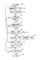
図5に、本実施例における強制モードを実行するフローチャートを示し、以下説明する。 FIG. 5 shows a flowchart for executing the forced mode in this embodiment, which will be described below.
プリント動作開始(S0)すると通常画像形成モードを実行し(S1)、枚数カウンタ20の値Pに1を足し値Pを更新する(S2)。
When the printing operation starts (S0), the normal image forming mode is executed (S1), and 1 is added to the value P of the
続いて、制御手段21で、枚数カウンタ20の値Pが所定枚数Pfix以上か否かを判断し(S3)、Pfix未満である場合は次なるプリント要求の有無を判断し(S4)、要求がある場合は画像形成モードを実行する(S1)。本実施例ではPfix=100枚に設定した。プリント要求が無い場合はプリントを終了する(S5)。
Subsequently, the control means 21 determines whether or not the value P of the
制御手段21で枚数カウンタ20の値Pが所定枚数Pfix以上か否かを判断し(S3)、Pfix以上の場合、つまり本実施例では100枚以上の場合、制御手段21は引き続き環境検知センサ12で検知した装置内温度Tが所定温度Tfixを超えているか否かを判断する(S6)。本実施例ではTfix=10℃に設定した。
The control means 21 determines whether or not the value P of the
環境検知センサ12で検知した装置内温度Tが所定温度Tfixを超えている場合は、前記した強制モードを実行し(S7)、枚数カウンタ20の値PをリセットP=0とする(S8)。
When the internal temperature T detected by the
続いて、プリント要求の有無を判断し(S4)、要求がある場合は通常画像形成モードを実行する(S1)。 Subsequently, the presence / absence of a print request is determined (S4). If there is a request, the normal image forming mode is executed (S1).
環境検知センサ12で検知した装置内温度Tが所定温度Tfix以下の場合は、強制モードを実行せず、そのままプリント要求の有無を確認する(S4)。
If the in-apparatus temperature T detected by the
S6にて、装置内温度Tが所定温度Tfix以下の場合は強制モードを実行しないが、枚数カウンタ20の値Pは装置内温度Tが所定温度Tfix以下でも通常画像形成モードを実行するたびに加算され続ける。
In S6, the forced mode is not executed when the apparatus temperature T is equal to or lower than the predetermined temperature Tfix, but the value P of the
このように枚数カウンタがPfix以上で、装置内温度Tが所定温度Tfixを超えた場合にのみ、強制モードが実行される構成とした。 As described above, the forced mode is executed only when the sheet counter is equal to or greater than Pfix and the apparatus internal temperature T exceeds the predetermined temperature Tfix.
つまり、環境検知センサ12によって検知された画像形成装置内の温度が所定値より高い場合には、印刷枚数100枚毎に強制モードを実施し、低い場合は、印刷枚数100枚毎のタイミングにおいても、強制モードを中止するような制御をすることにより、クリーニングブレード51の反発弾性率が温度低下によって低下した時には、強制モードにて発生する大量のトナーをクリーニングする必要が無くなるので、感光ドラム2のクリーニング不良を防止した。
That is, when the temperature in the image forming apparatus detected by the
上記、本実施例の画像形成装置にて、5℃〜20℃の範囲で変化する冬季のオフィス環境下で、数日かけて約5000枚の画像形成を実施したが、一度もクリーニング不良を招くことなく且つ濃度低下やかぶり等の画像不良の無い良好な画像が得られ続けた。 In the image forming apparatus according to the present embodiment, about 5000 sheets of images were formed over several days in a winter office environment changing in the range of 5 ° C. to 20 ° C. Good images without image defects such as density reduction and fogging were continuously obtained.
以上説明したように、本実施例では、(1)画像形成装置内部の温度が所定温度よりも高い場合(第1の環境)は、現像装置から非画像形成時における強制的に感光ドラムに転移させるトナー量(現像剤転移量)を、現像剤担持体又は現像剤供給部材上の1周分以上として、且つ(2)画像形成装置内部の温度が所定温度よりも低くなった場合(第2の環境)は、感光ドラムに対して劣化トナーを転移する動作を行わないので、現像装置内のトナー劣化に伴うかぶりや濃度低下のない良好な画質を得られるとともに、クリーニングブレードの良好なクリーニング性を維持することの両立が可能となった。 As described above, in this embodiment, (1) when the temperature inside the image forming apparatus is higher than the predetermined temperature (first environment), the developing device is forcibly transferred to the photosensitive drum during non-image formation. The amount of toner to be transferred (developer transfer amount) is set to be equal to or greater than one turn on the developer carrier or developer supply member, and (2) the temperature inside the image forming apparatus is lower than a predetermined temperature (second) Environment) does not perform the operation of transferring the deteriorated toner to the photosensitive drum, so that it is possible to obtain good image quality without fogging and density reduction due to toner deterioration in the developing device, and good cleaning performance of the cleaning blade. It has become possible to maintain both.
尚、本実施例においては、クリーニングブレード51の反発弾性率が低下する低温環境の10℃を閾値とし、強制モードの実行する、若しくは禁止する構成で説明したが、使用するクリーニングブレードの特性に応じて温度閾値Tfixを適宜可変しても良い。
In the present embodiment, the configuration has been described in which the forced mode is executed or prohibited with a threshold of 10 ° C. in a low-temperature environment where the rebound resilience of the
又、本実施例では100枚の所定枚数画像形成ごとに強制モードを実行する構成で説明したが、所定枚数Pfixはこの値に限る必要はなく、現像装置構成ならびに使用するトナー耐久性に応じて適宜可変しても良い。また通常画像形成モードを実行した現像装置の稼働時間を積算し所定稼働時間ごとに強制モードを実行する構成としても良い。 In this embodiment, the forced mode is executed every time a predetermined number of 100 images are formed. However, the predetermined number Pfix need not be limited to this value, and depends on the configuration of the developing device and the durability of the toner used. It may be varied as appropriate. Alternatively, the operation time of the developing device that has executed the normal image forming mode may be integrated and the forced mode may be executed every predetermined operation time.
又、本実施例では強制モード時のスキャナユニット1副走査方向の露光幅をトナー供給ローラ43の1周分相当に設定したが、使用する現像ローラ42の直径及び周速度、並びに使用するトナー供給ローラ43の直径及び周速度に応じてスキャナユニット1の副走査方向の露光幅を適宜変更してもよい。しかし、トナー転移量を、現像ローラや現像剤供給ローラ等の部材の1周分相当量以上とすることで。現像装置の初期化は達成され、本実施例同様のかぶりや濃度低下のない良好な画質が維持できる。
In this embodiment, the exposure width in the scanning direction of the
ここで、上記に説明したように、現像ローラ42表面に担持するトナー層厚は現像ブレード44によって規制されているので一定であるので、現像ローラ42の1周分にて担持できるトナー量も一定となる。従って、本明細書では、トナー転移量が現像ローラ42の周長によって規定でき、又、現像ローラ42に従動しているトナー供給ローラ43の周長によっても規定できる。
Here, as described above, since the thickness of the toner layer carried on the surface of the developing
実施例2
強制モードにおいて、実施例1では、装置本体内の温度が所定値以下の低温低湿環境の時に、強制モードを中止する動作を行ったが、本実施例では、所定温度以下の場合の低温強制モードと、所定湿度以下の場合の低湿強制モードと、の2種類の強制モードを実行するようにしたことを特徴とする。
Example 2
In the forced mode, in the first embodiment, the operation for canceling the forced mode is performed when the temperature in the apparatus main body is a low temperature and low humidity environment where the temperature in the apparatus main body is a predetermined value or less. And a low-humidity forced mode when the humidity is below a predetermined humidity, and two forced modes are executed.
尚、実施例1で説明した画像形成装置ならびにプロセスカートリッジの基本構成は同一であり、同じ部材は同一の符号を付し詳細な説明を割愛する。
The basic configurations of the image forming apparatus and the process cartridge described in
クリーニング装置5は、感光ドラム2上のトナー41を回収する装置であり、又、一般にトナーは雰囲気の湿度に応じて帯電特性が変化する性質を持っていることが知られている。トナー41は主に現像装置4の現像ブレード44を通過する際に現像ローラ42の駆動に伴う摺擦によって摩擦帯電電荷を与えられる。この摩擦帯電電荷は雰囲気の湿度によって大きく変化し、湿度が低い場合は摩擦帯電電荷は多くなるとともに与えられた電荷が気中に放電しないため、高電荷状態で長時間保持される。そして、摩擦帯電電荷の大きいトナーはクーロン力が大きいため、感光ドラム2への付着力も強くなるので、低湿環境下のトナーは、クリーニングブレード51をわずかながらすり抜けてしまう場合があった。
The
つまり、低湿環境下では、トナーのクリーニングブレード51からのすり抜けが発生し、感光ドラム2のクリーニング不良が発生した。
That is, in a low humidity environment, toner slipped out from the
従って、本実施例では、実施例1にて説明した現像剤転移制御において、強制モードを実行しなかった低温環境下にては、強制モードを中止せずに内容を変更して、低温強制モードが実行されるようにした。そして、低温環境下では、更に、環境センサ12によって、湿度が所定値以下かどうかを検知して、所定値以上では100枚毎の強制モードを実施し、所定値以下の時は、やはり強制モードの内容を変更して低湿強制モードを実施した。そして、これらの低温強制モード、低湿強制モードにおいては、強制モードにおけるトナー転移量を減らす動作が行われるようにした。以下にその構成を図4ならびに図6を用いて説明する。
Therefore, in this embodiment, in the developer transfer control described in the first embodiment, in the low temperature environment where the forced mode is not executed, the content is changed without stopping the forced mode, and the low temperature forced mode is set. Was made to run. In a low temperature environment, the
ここで、実施例1に説明した強制モードと同様の、低温低湿環境でない場合に、100枚毎に実行される非画像形成時における現像装置4から感光ドラム2へのトナーの吐き出しを行う強制モードを、第1の強制モードと称す。
Here, the forced mode for discharging toner from the developing
第1の環境として低温低湿環境でない場合、つまり環境検知センサ12によって検知される温度が所定温度以下でなく且つ湿度が所定湿度以下でない場合は、本実施例では、第1の強制モードとして、実施例1と同様に、制御手段21が、それに接続された枚数カウンタ20の値を読み込み、所定枚数、ここでは100枚毎に強制的にトナーを転移させて、枚数カウンタ20のカウント値をリセットして通常画像形成モード実行枚数を再び積算する動作が行われる。
When the first environment is not a low-temperature and low-humidity environment, that is, when the temperature detected by the
この第1の強制モードの具体的な動作としては、通常画像形成モードを一次中断し、転写材7の搬送を停止させ、つまり非画像形成時の状態として、スキャナユニット1から主走査方向全域で且つ副走査方向に所定幅、ここでは41.8mmの露光を実施し、ホストコンピュータ等から入力された画像情報とは異なる潜像を形成する。この潜像に従って現像装置4によって現像バイアス電圧VdcとしてVdc=−300Vが印加され現像装置4内のトナー41が感光ドラム2に転移され現像装置4内のトナーは初期化される。そして、感光ドラム2に転移したトナー41は感光ドラム2の回転に伴ってクリーニング装置5に回収される。つまり、環境センサ12により、画像形成装置内部の温度又は湿度が所定値を超えているか否かを常に判断し、環境が低温低湿環境でない場合は、実施例1にて図4、図5を用いて説明した強制モードと同様の第1の強制モードを実行する。
As a specific operation of the first forced mode, the normal image forming mode is temporarily interrupted, the conveyance of the
そして、本実施例にては、温度又は湿度が所定値以下の場合は、画像形成100枚ごとの第1の強制モードを変更して、低温強制モード又は低湿強制モードを実行する。 In this embodiment, when the temperature or humidity is equal to or lower than a predetermined value, the first forced mode for every 100 sheets of image formation is changed, and the low temperature forced mode or the low humidity forced mode is executed.
そして、低温強制モードとは、具体的にはクリーニングブレード51の反発弾性率が低下する低温環境の10℃を閾値とし、装置内部が10℃以下の場合に、トナーが感光ドラム2に対してトナー41が転移しないように、スキャナユニット1からの露光を停止させる動作が行われるものとした。このとき現像バイアス等の他の条件は、第1の強制モードと同様に行われる。
The low temperature forced mode is specifically the low temperature environment where the rebound resilience of the
低温環境にて低温強制モードによって、クリーニング装置5に回収されるトナーが、通常画像形成モードにおいては転写残りトナーであり、その単位面積あたりのトナー量が少ないのに対して、強制モードにおけるトナー量は転写工程を経ないので転写残りトナーよりもはるかに多い量となり、反発弾性率が低下する低温環境ではクリーニング不良を招く頻度が増すことを防止できる。実施例1では、強制モードそのものを停止したが、本実施例では、低温強制モードを実行し、この低温強制モードでは感光ドラム2へ転移するトナー量はほとんど無い状態となった。
The toner collected by the
そして、低湿強制モードとは、具体的にはクリーニングブレード51の摩擦帯電電荷が大きくなる低湿環境の30%RHを閾値とし、装置内部が30%RH以下の場合に、画像形成100枚ごとの強制モードにおける現像バイアス電圧Vdcを変更させて、感光ドラム2への転移量を少なくするようにした。本実施例ではVdc=−150Vとした。
The low-humidity forced mode specifically refers to a low-humidity environment where the triboelectric charge of the
これは、低湿化におけるトナーの摩擦帯電電荷の増大によるクリーニングブレード51からのすり抜けへの対策のためであり、反転現像方法を用いている本実施例においては現像バイアス電圧Vdcを第1の強制モードのVdc=−300Vに対し低湿強制モードの現像バイアス電圧VdcをVdc=−150Vとすることで、明部表面電位Vlの電位Vl=−100Vに対する電位差を小さくし、第1の強制モードに比べ、感光ドラム2に転移させるトナー量を少なくするためである。このとき現像バイアス等の他の条件は、第1の強制モードと同様に行われる。
This is to prevent slipping from the
この低湿強制モードにて、トナーがクリーニングブレード51をすり抜けてしまう頻度を大幅に減らすことができた。
In this low humidity forced mode, the frequency with which the toner slips through the
この際、転写帯電器6を転写材7を介さずにトナー41が通過するので、第1の強制モードと同様に転写帯電器6の汚れを防止するため転写バイアス電圧VtrをVtr=0Vに設定した。
At this time, since the
図6に本実施例のフローチャートを示し、以下説明する。 FIG. 6 shows a flowchart of this embodiment, which will be described below.
プリント動作開始(S0)すると通常画像形成モードを実行し(S1)、枚数カウンタ20の値Pに1を足し値Pを更新する(S2)。
When the printing operation starts (S0), the normal image forming mode is executed (S1), and 1 is added to the value P of the
続いて、制御手段21で枚数カウンタ20の値Pが所定枚数Pfix以上か否かを判断し(S3)、Pfix未満である場合は次なるプリント要求の有無を判断し(S8)、要求がある場合は通常画像形成モードを実行する(S1)。本実施例ではPfix=100枚に設定した。
Subsequently, the control means 21 determines whether or not the value P of the
プリント要求が無い場合はプリントを終了する(S9)。 If there is no print request, the printing is terminated (S9).
制御手段21で枚数カウンタ20の値Pが所定枚数Pfix以上か否かを判断し(S3)、Pfix以上の場合、本実施例では100枚以上の場合、制御手段21は引き続き環境検知センサ12で検知した装置内温度Tが所定温度Tfixを超えているか否かを判断する(S4)。本実施例ではTfix=10℃に設定した。
The control means 21 determines whether or not the value P of the
環境検知センサ12で検知した装置内温度Tが所定温度Tfixを超えている場合は、引き続き、制御手段21は環境検知センサ12で検知した装置内湿度Hが所定温度Hfixを超えているか否かを判断する(S5)。本実施例ではHfix=30%RHに設定した。
When the internal temperature T detected by the
環境検知センサ12で検知した装置内湿度Hが所定湿度Hfixを超えている場合は、前記した第1の強制モードを実行し(S6)、枚数カウンタ20の値PをリセットP=0とする(S7)。
When the internal humidity H detected by the
続いて、プリント要求の有無を判断し(S8)、要求がある場合は通常画像形成モードを実行する(S1)。 Subsequently, the presence / absence of a print request is determined (S8). If there is a request, the normal image forming mode is executed (S1).
ここで、制御手段21が、環境検知センサ12で検知した装置内温度Tが所定温度Tfixを超えているか否かを判断し(S4)、装置内温度Tが所定温度Tfix以下の場合は、低温強制モードに移行し、具体的にはスキャナユニット1の露光を行わずに、現像バイアス電圧VdcをVdc=−300Vした状態で現像装置4を駆動させ、感光ドラム2にトナーが転移しない状態のまま強制モード動作をあたかも実施したかのような動作をする(S10)。
Here, the control means 21 determines whether or not the in-apparatus temperature T detected by the
その後枚数カウンタの値Pに変化を加えずに、プリント要求の有無を確認する(S8)。 Thereafter, the presence or absence of a print request is confirmed without changing the value P of the number counter (S8).
このようにすることで装置内温度Tが所定温度Tfix以下の場合は低温強制モードに移行し、感光ドラム2へのトナー転移は実際には行われない。
In this way, when the apparatus internal temperature T is equal to or lower than the predetermined temperature Tfix, the mode is shifted to the low temperature forced mode, and toner transfer to the
しかし、枚数カウンタ20の値Pは装置内温度Tが所定温度Tfix以下でも通常画像形成モードを実行するたびに加算され続ける。
However, the value P of the
このように、装置内温度Tが所定温度Tfixを超えた場合は第1の強制モードが実行され、所定温度Tfixより低い場合は、低温モードを実行する。 Thus, the first forced mode is executed when the in-device temperature T exceeds the predetermined temperature Tfix, and the low temperature mode is executed when it is lower than the predetermined temperature Tfix.
又、制御手段21が環境検知センサ12で検知した装置内湿度Hが所定湿度Hfixを超えているか否かを判断して(S5)、装置内湿度Hが所定湿度Hfix以下の場合は、低湿強制モードに移行し、具体的には現像バイアス電圧VdcをVdc=−150Vに変更し、感光ドラム2へのトナー転移量が少なくなるようにする(S11)。その後、枚数カウンタ20の値PをリセットP=0とする(S12)。続いて、プリント要求の有無を判断し(S8)、要求がある場合は通常画像形成モードを実行する(S1)。
Further, it is determined whether or not the internal humidity H detected by the
上記、本実施例の画像形成装置にて、温度5℃〜20℃、湿度20%RH〜50%RHの範囲で変化する冬季のオフィス環境下で、数日かけて約5000枚の画像形成を実施したが、一度もクリーニング不良を招くことなく且つ濃度低下やかぶり等の画像不良の無い良好な画像が得られ続けた。 With the image forming apparatus of the present embodiment, about 5000 images can be formed over several days in a winter office environment where the temperature changes in the range of 5 ° C. to 20 ° C. and humidity of 20% RH to 50% RH. Although it was carried out, a good image without image defects such as density reduction and fogging was continuously obtained without causing any cleaning failure.
以上説明したように、(1)画像形成装置内部の温度又は湿度が所定温度よりも高い場合(第1の環境)は、第1の強制モードを実行させ、所定枚数毎に強制的に感光ドラムに転移させる劣化トナー量を、現像剤担持体又は現像剤供給部材上の1周分相当量としつつ、又、(2)画像形成装置内部の温度が所定温度よりも低くなった場合(第2の環境)は、低温強制モードを実行し、強制的に感光ドラムに対して転移させるトナー量を少なくさせるかトナーが全く転移しないようにし、又、(3)画像形成装置内部の湿度が所定湿度よりも低くなった場合(第2の環境)は、同様に、強制的に感光ドラムに対して転移させるトナー量を減らす動作を実施することで、現像装置内のトナー劣化に伴うかぶりや濃度低下のない良好な画質を得られるとともに、クリーニングブレードの良好なクリーニング性を維持することの両立が可能となった。 As described above, (1) when the temperature or humidity inside the image forming apparatus is higher than the predetermined temperature (first environment), the first forced mode is executed, and the photosensitive drum is forcibly executed every predetermined number of sheets. (2) When the temperature inside the image forming apparatus becomes lower than a predetermined temperature while the amount of the deteriorated toner to be transferred to is set to an amount equivalent to one rotation on the developer carrier or developer supply member (second (3) The low temperature forced mode is executed to reduce the amount of toner to be forcibly transferred to the photosensitive drum or to prevent the toner from transferring at all, and (3) the humidity inside the image forming apparatus is a predetermined humidity. In the same manner, the operation of forcibly reducing the amount of toner transferred to the photosensitive drum is carried out to reduce fog and density due to toner deterioration in the developing device. Good image quality without Together, it became possible to achieve both maintaining good cleaning performance of the cleaning blade.
更には、第1の強制モード、低温強制モード、低湿強制モードにおいて、機械的な装置動作状態を全て同じとし、スキャナユニット1の露光/非露光ならびに現像バイアス電圧設定のみの相違とした構成としたことで、本体制御シーケンス情報を多数持つ必要もなくなるため、制御用ICの小容量化に貢献でき、コストを抑えられる等のメリットも有す。
Furthermore, in the first forced mode, the low temperature forced mode, and the low humidity forced mode, the mechanical apparatus operating state is all the same, and only the exposure / non-exposure of the
尚、本実施例における温度及び湿度の閾値は、これに限らず、適宜決定する。 Note that the threshold values of temperature and humidity in the present embodiment are not limited to this and are appropriately determined.
又、低温強制モードにて、現像バイアスを変更してもよく、低湿強制モードにて、露光装置を停止してもよく、両者の動作を逆にしてもよい。つまり、第1の強制モードより現像装置4から感光ドラム2へと転移する転移現像剤量が少なければその動作は適宜選択する。
Further, the developing bias may be changed in the low temperature forced mode, the exposure apparatus may be stopped in the low humidity forced mode, and the operations of both may be reversed. That is, if the amount of transfer developer transferred from the developing
実施例3
本実施例は、上記実施例2の効果を、他の態様で実現することを特徴としている。
Example 3
The present embodiment is characterized in that the effect of the second embodiment is realized in another manner.
尚、実施例1及び実施例2で説明した画像形成装置ならびにプロセスカートリッジと同じ部材は同一の符号を付し詳細な説明を割愛する。 The same members as those in the image forming apparatus and the process cartridge described in the first and second embodiments are denoted by the same reference numerals, and detailed description thereof is omitted.
以下に本実施例の構成を図7ならびに図8を用いて説明する。 The configuration of this embodiment will be described below with reference to FIGS.
本実施例では、実施例2同様に、環境検知センサ12によって検知された温度が10℃以下か若しくは湿度が30%RH以下の場合に、第1の強制モードを変更し、露光を停止したり、現像バイアスを変更したりする低温強制モード、低湿強制モードを実行する。
In this embodiment, as in the second embodiment, when the temperature detected by the
即ち、制御手段21には環境検知センサ12が接続され画像形成装置内部の環境を検知している。本実施例では環境検知センサ12は画像形成装置内部の温度及び湿度を検知しており、制御手段21は画像形成装置内部の温度又は湿度が所定値を超えているか否かを常に判断しており、所定値以下の場合、画像形成100枚ごとに行われる強制モードを変更する構成とした。
In other words, the
具体的には、クリーニングブレード51の反発弾性率が低下する低温環境の10℃を閾値とし、装置内部が10℃以下の場合は、所定枚数、100枚毎の強制モードのタイミングになっても、感光ドラム2に対してトナー41が転移しないようにスキャナユニット1からの露光を止める。そして、本実施例の特徴としては、図7に示されるように、制御手段21が、現像駆動手段である現像モータ47の駆動回路に接続され、低温強制モードにて、更に、現像装置4に駆動を入力する現像モータ47の駆動を停止させる。このようにして、本実施例の低温強制モードでは感光ドラム2へ転移するトナー量が無い状態とし、さらに現像装置4の駆動を停止しトナーの劣化を抑制した。
Specifically, the threshold is 10 ° C. in a low-temperature environment where the rebound resilience of the
つまり、低温強制モードにて、実施例2では、露光を停止するのみだったが、本実施例では、更に、現像装置4の駆動を停止させた。
That is, in the low-temperature forced mode, only the exposure is stopped in the second embodiment, but the driving of the developing
画像形成装置内部の湿度が所定値以下の場合は、実施例2と同様に、画像形成100枚毎の第1の強制モードにおける現像バイアス電圧Vdcを変更し、感光ドラム2へのトナー転移量を少なくする低湿強制モードを実行した。本実施例ではVdc=−150Vとした。低湿強制モードでは、前記のように低湿化ではトナーの摩擦帯電電荷が大きくなるが、トナーはクーロン力が大きいため、感光ドラム2への付着力も強くなるので、クリーニングブレード51をわずかながらすり抜けてしまうという問題が生じるため、この問題への対策として、反転現像方法を用いている本実施例においては現像バイアス電圧Vdcを第1の強制モードのVdc=−300Vに対し、低湿強制モードの現像バイアス電圧VdcをVdc=−150Vとすることで、明部表面電位Vlの電位Vl=−100Vに対する電位差を小さくし、第1の強制モードに比べ感光ドラム2に転移させるトナー量を少なくするものとした。こうすることで、トナーがクリーニングブレード51をすり抜けてしまう頻度を大幅に減らすことができる。この際、転写帯電器6を転写材7を介さずにトナー41が通過するので転写帯電器6の汚れを防止するため転写バイアス電圧VtrをVtr=0Vに設定した。
When the humidity inside the image forming apparatus is equal to or lower than the predetermined value, the developing bias voltage Vdc in the first forced mode for every 100 sheets of image forming is changed to change the toner transfer amount to the
図8に本実施例のフローチャートを示し、以下説明する。 FIG. 8 shows a flowchart of this embodiment, which will be described below.
プリント動作開始(S0)すると画像形成モードを実行(S1)し、枚数カウンタ20の値Pに1を足し値Pを更新する(S2)。
When the printing operation starts (S0), the image forming mode is executed (S1), and 1 is added to the value P of the
続いて、制御手段21で枚数カウンタ20の値Pが所定枚数Pfix以上か否かを判断し(S3)、Pfix未満である場合は次なるプリント要求の有無を判断し(S8)、要求がある場合は通常画像形成モードを実行する(S1)。本実施例ではPfix=100枚に設定した。
Subsequently, the control means 21 determines whether or not the value P of the
プリント要求が無い場合はプリントを終了する(S9)。 If there is no print request, the printing is terminated (S9).
制御手段21で枚数カウンタ20の値Pが所定枚数Pfix以上か否かを判断し(S3)、Pfix以上の場合、本実施例では100枚以上の場合、制御手段21は引き続き環境検知センサ12で検知した装置内温度Tが所定温度Tfixを超えているか否かを判断する(S4)。本実施例ではTfix=10℃に設定した。
The control means 21 determines whether or not the value P of the
環境検知センサ12で検知した装置内温度Tが所定温度Tfixを超えている場合は、引き続き、制御手段21は環境検知センサ12で検知した装置内湿度Hが所定湿度Hfixを超えているか否かを判断する(S5)。本実施例ではHfix=30%RHに設定した。
When the internal temperature T detected by the
環境検知センサ12で検知した装置内湿度Hが所定湿度Hfixを超えている場合は、前記した第1の強制モードを実行し(S6)、枚数カウンタ20の値PをリセットP=0とする(S7)。
When the internal humidity H detected by the
続いて、プリント要求の有無を判断し(S8)、要求がある場合は通常画像形成モードを実行する(S1)。 Subsequently, the presence / absence of a print request is determined (S8). If there is a request, the normal image forming mode is executed (S1).
ここで制御手段21が環境検知センサ12で検知した装置内温度Tが所定温度Tfixを超えているか否かを判断し(S4)、装置内温度Tが所定温度Tfix以下の場合は、低温強制モードに移行し、具体的にはスキャナユニット1の露光を行わずに、現像バイアス電圧VdcをVdc=−300Vにした状態で、且つ現像モータ47の駆動を停止し、現像装置4を非稼動とさせ、感光ドラム2にトナーが転移しない状態のまま強制モード動作をあたかも実施したかのような動作をするものである(S10)。
Here, it is determined whether or not the internal temperature T detected by the
その後枚数カウンタの値Pに変化を加えずに、プリント要求の有無を確認する(S4)。 Thereafter, the presence / absence of a print request is confirmed without changing the value P of the number counter (S4).
このようにすることで装置内温度Tが所定温度Tfix以下の場合は、低温強制モードに移行し、感光ドラム2へのトナー転移は実際には行わないのだが、枚数カウンタ20の値Pは装置内温度Tが所定温度Tfix以下でも、通常画像形成モードを実行するたびに加算され続ける。つまり、装置内温度Tが所定温度Tfixを超えた場合は第1の強制モードが実行される構成とした。
In this way, when the apparatus internal temperature T is equal to or lower than the predetermined temperature Tfix, the low temperature forced mode is entered and the toner transfer to the
又、制御手段21が環境検知センサ12で検知した装置内湿度Hが所定湿度Hfixを超えているか否かを判断し(S5)、装置内湿度Hが所定湿度Hfix以下の場合は、低湿強制モードに移行し、具体的には現像バイアス電圧VdcをVdc=−150Vにし、感光ドラム2へのトナー転移量が少なくなる状態で強制モードを実施する(S11)。
Further, the control means 21 determines whether or not the internal humidity H detected by the
その後、枚数カウンタ20の値PをリセットP=0とする(S12)。続いて、プリント要求の有無を判断し(S8)、要求がある場合は通常画像形成モードを実行する(S1)。
Thereafter, the value P of the
上記、本実施例の画像形成装置にて、温度2℃〜15℃、湿度20%RH〜45%RHの範囲で変化する冬季のプレハブ等の簡易住居環境下で、数日かけて約5000枚の画像形成を実施したが、一度もクリーニング不良を招くことなく且つ濃度低下やかぶり等の画像不良の無い良好な画像が得られ続けた。 In the image forming apparatus of the present embodiment, about 5000 sheets over a few days in a simple residential environment such as a prefab in winter that changes in a temperature range of 2 ° C. to 15 ° C. and a humidity range of 20% RH to 45% RH. However, it was possible to obtain a good image without causing any defective cleaning such as a decrease in density or fogging.
尚、本実施例における温度及び湿度の閾値は、これに限らず、適宜決定する。 Note that the threshold values of temperature and humidity in the present embodiment are not limited to this and are appropriately determined.
以上説明したように、(1)画像形成装置内部の温度が所定温度よりも高い場合(第1の環境)は、第1の強制モードを実行させ、所定枚数毎に強制的に感光ドラム2に対して転移させる劣化トナー量を、現像ローラ42又はトナー供給ローラ43上の1周分相当量としつつ、又、(2)画像形成装置内部の温度が所定温度よりも低くなった場合(第2の環境)は、低温強制モードを実行し、強制的に感光ドラム2に対して現像装置4の稼動を停止し、トナー41が全く転移しないようにし、又、(3)画像形成装置内部の湿度が所定湿度よりも低くなった場合(第2の環境)は、強制的に感光ドラム2に対して転移させる劣化トナー量を減らす動作を実施することで、現像装置4内のトナー劣化に伴うかぶりや濃度低下のない良好な画質を得られることに加え、本実施例のように、低温環境下が比較的長い時間にあっても現像装置4の稼動を停止することで、トナーの劣化が余計に進行することを防止しつつ、クリーニングブレード51の良好なクリーニング性を維持することの両立が可能となった。
As described above, (1) when the temperature inside the image forming apparatus is higher than the predetermined temperature (first environment), the first forced mode is executed, and the
尚、現像モータ47の駆動を停止する制御は、低湿強制モードにて行ってもよい。
The control for stopping the driving of the developing
実施例4
本実施例においても、画像形成装置内部の環境変化に応じて強制的に感光ドラムに対して転移させる劣化トナー量を変更することで、現像性を損なうことなく、クリーニングブレードの良好なクリーニング性を維持させる。しかし、低温低湿環境において、強制モードを実行しないと、現像装置から感光ドラムに転移する劣化トナー量が少なくなるので、現像装置内に劣化トナーが蓄積していく。そこで、本実施例の特徴としては、強制モードにおける露光時間をカウントし、この露光時間に対応するように、非画像形成時に、現像装置から、低温低湿環境にて転移させなかった分のトナーを露光部に移動させることで、現像装置内の劣化トナーを消費させるものである。
Example 4
Also in this embodiment, by changing the amount of deteriorated toner that is forcibly transferred to the photosensitive drum according to the environmental change in the image forming apparatus, it is possible to improve the cleaning performance of the cleaning blade without impairing the developability. Let it be maintained. However, if the forced mode is not executed in a low-temperature and low-humidity environment, the amount of deteriorated toner transferred from the developing device to the photosensitive drum decreases, and therefore deteriorated toner accumulates in the developing device. Therefore, as a feature of the present embodiment, the exposure time in the forced mode is counted, and the toner that is not transferred from the developing device in the low-temperature and low-humidity environment is formed during non-image formation so as to correspond to the exposure time. By moving to the exposure unit, the deteriorated toner in the developing device is consumed.
本実施例の特徴を詳しく説明する。尚、実施例1で説明した画像形成装置ならびにプロセスカートリッジの基本構成は同一であり、同じ部材は同一の符号を付し詳細な説明を割愛する。
The features of this embodiment will be described in detail. The basic configurations of the image forming apparatus and the process cartridge described in
本実施例における現像装置4内のトナー41を初期化させるために、ここでも、図9に示すように、実施例1同様に、制御手段21は、露光装置1、現像装置4、転写帯電器6などに接続しており、不図示のホストコンピュータ等から入力された画像情報に基づいて転写材7に画像形成を行うための制御を行うものである。
In order to initialize the
制御手段21には枚数カウンタ20が接続され、枚数カウンタ20は通常画像形成モードで画像出力した転写材の枚数をカウントするものである。制御手段21は枚数カウンタ20の値を読み込み、所定枚数に達すると現像装置4から感光ドラム2に対して強制的にトナーを転移させる強制モードを実行する。本実施例では、100枚毎に強制モードを実施させた。
A
そして強制モードを実行するたびに枚数カウンタ20のカウント値をリセットして通常画像形成モード実行枚数を再び積算する構成としている。
Each time the forced mode is executed, the count value of the
強制モードの具体的な動作を説明すると、制御手段21では通常画像形成モードを一次中断し、転写材7の搬送を停止させ、露光装置1から主走査方向全域に渡り副走査方向に所定幅の露光を実施し、ホストコンピュータ等から入力された画像情報とは異なる潜像を形成する。
The specific operation of the forced mode will be described. The
そして、現像装置4には、現像バイアス電圧が印加され、現像装置4内のトナー41が強制モードにおいて感光ドラム2表面に形成された上記通常画像とは別の潜像に転移され、現像装置内4のトナーは初期化される。
Then, a developing bias voltage is applied to the developing
強制モードによって、感光ドラム2に転移したトナー41は、感光ドラム2の回転に伴ってクリーニング装置5に回収されるが、この際、転写帯電器6を転写材7を介さずにトナー41が通過するので転写帯電器6の汚れを防止するため転写バイアス電圧VtrをVtr=0Vに設定した。
In the forced mode, the
ここまでは、実施例1の強制モードや実施例2、3の第1の強制モードと同様であるが、本実施例では、図9に示すように、制御手段21には強制モード実行中の露光時間をカウントする露光タイマー19が接続され、強制モードにおける露光時間を基準とした不足露光時間が記録される。本実施例にて実行される、露光タイマー19を用いた、上記に説明した強制モードを第2の強制モードと称す。
Up to this point, it is the same as the forced mode of the first embodiment and the first forced mode of the second and third embodiments, but in this embodiment, as shown in FIG. An
ここで、第2の強制モード実行中の露光時間とは、第2の強制モード実行中に感光ドラム2を実際にレーザ照射している時間で規定する。つまり、露光タイマー19がカウントする露光時間は、第2の強制モードにおいて、現像装置4内のトナー41が感光ドラム2に転移した量に対応する。
Here, the exposure time during execution of the second forced mode is defined by the time during which the
具体的には、露光タイマー19では、画像形成装置内部において環境が変化せず、ずっと所定よりも温度湿度が高い値にあり、印刷枚数によるタイミングで即ち100枚毎に確実に強制モードが実行されている状態を基準とする。即ち、強制モードが確実に100枚毎に実施されて、露光時間が消費されると0となり、低温低湿環境に環境が変化した場合等で、強制モードが中止されたり、露光面積が減ったりすると、その分の露光時間がカウントされる。尚、ここでは、感光ドラムは一定速度で回転しており、主走査方向の幅は一定であるので、露光時間とは、副走査方向を操作する時間となり、露光面積は露光時間と同義となる。
Specifically, in the
又、第2の強制モードにおける露光装置1の副走査方向の露光幅は、現像ローラ42又はトナー供給ローラ43の1周分相当以上とすることが良い。
Further, the exposure width in the sub-scanning direction of the
なぜなら、本実施例では現像ローラ42の1周分は33.4mmで、トナー供給ローラ43の1周分は41.8mmであるので、副走査方向の露光幅としてはトナー供給ローラ43の1.5周分相当の62.7mmに設定することで、現像ローラ42も1周以上相当し、両部材同時に外周面のトナーを強制的に転移することが可能となるからである。
This is because, in this embodiment, one rotation of the developing
この場合、強制モード実行中の露光時間は0.6秒となる。従って本実施例では上述した露光タイマー19の基準露光時間は0.6秒とする。このことで、供給ローラ54と現像ローラ42との両方のローラ42と43の1周分にて担持される量の現像剤を静電潜像に吐き出すことができる。
In this case, the exposure time during execution of the forced mode is 0.6 seconds. Therefore, in this embodiment, the reference exposure time of the above-described
ここで、上記に説明したように、現像ローラ42表面に担持するトナー層厚は現像ブレード44によって規制されているので一定であるので、現像ローラ42の1周分にて担持できるトナー量も一定となる。従って、本明細書では、トナー転移量が現像ローラ42の周長によって規定でき、又、現像ローラ42に従動しているトナー供給ローラ43の周長によっても規定できる。
Here, as described above, since the thickness of the toner layer carried on the surface of the developing
一方、制御手段21には、環境検知センサ12も接続され、画像形成装置内部の環境を検知している。本実施例では環境検知センサ12は画像形成装置内部の温度を検知しており、制御手段21は画像形成装置内部の温度が所定値を超えているか否かを常に判断しており、所定値以下の場合、画像形成100枚ごとの強制モードを禁止する構成とした。
On the other hand, the
具体的には、クリーニングブレード51の反発弾性率が低下する低温環境の10℃を閾値として装置内部が10℃以下の場合は、強制モードを実行しない構成とした。これは、クリーニング装置5に回収されるトナーが、通常画像形成モードにおいては転写残りトナーでありその単位面積あたりのトナー量が少ないのに対して、第2の強制モードにおけるトナー量は転写工程を経ないので転写残りトナーよりもはるかに多い量となり、反発弾性率が低下する低温環境ではクリーニング不良を招く頻度が増すことを防止するためである。
Specifically, the forced mode is not executed when the inside of the apparatus is 10 ° C. or lower with a threshold of 10 ° C. in a low temperature environment where the impact resilience of the
本実施例では、このように画像形成100枚毎の強制モードが禁止された場合は、露光タイマー19の値は画像形成100枚毎に0.6秒ずつ加算される。つまり、低温低湿環境が続く等で、第2の強制モードが実行されないと露光タイマーのカウント数が蓄積されることとなる。
In this embodiment, when the forced mode for every 100 image formations is prohibited as described above, the value of the
又、第2の強制モードが100枚毎に実行されないと、その分現像装置4内の劣化トナー量が増加するので、一回の第2の強制モードにて、現像装置4から感光ドラム2へ転移するトナー量が増加する。しかし、第2の強制モードにおけるトナー転移1回当たりに感光ドラム2に転移させるトナー量が、供給ローラ43の1〜1.5周相当量の場合は、クリーニング不良の発生は見られなかった。
If the second forced mode is not executed every 100 sheets, the amount of deteriorated toner in the developing
しかし、上述したトナー転移量を供給ローラ43の2周相当量以上とすると、ゴムの反発弾性率が徐々に低下し始める温度(本実施例では15℃付近に相当)では、クリーニングブレード51に負担がかかり、わずかながらクリーニング不良の発生が見られた。尚、使用するクリーニングブレード51の特性に応じて温度閾値Tfixを適宜可変しても良い。
However, if the toner transfer amount is equal to or greater than the two-round equivalent of the
そこで、クリーニング不良を回避するため、本実施例では第2の強制モードにおけるトナー転移量をトナー供給ローラ43の2周分相当量までとした。
Therefore, in order to avoid a cleaning failure, in this embodiment, the toner transfer amount in the second forced mode is set to an amount corresponding to two rotations of the
そして、画像形成装置内の温度が所定値(ここでは10℃)以上且つ露光タイマー19の値が0の場合は、上述した第2強制モードを実行するが、露光タイマー19の値が0を超えていた場合は、露光タイマー19の値が0になるまで、1回当たりに強制転移するトナー量を第2の強制モードよりも多くする構成とした。このように、1回当たりに強制転移させるトナー量を第2の強制モードよりも多くするモードを復帰強制モードと称す。
When the temperature in the image forming apparatus is equal to or higher than a predetermined value (here, 10 ° C.) and the value of the
具体的には、画像形成装置内の温度が10℃以上且つ露光タイマー19の値が0を超えていた場合は、1回あたりの強制転移を、第2の強制モードでは、トナー供給ローラ43の1.5周分であるところを、トナー供給ローラ43の2周分相当の83.6mmとする構成とした。
Specifically, when the temperature in the image forming apparatus is 10 ° C. or more and the value of the
これは、第2の強制モードでトナーの転移量が減少してしまうことにより現像装置4内のトナー劣化が進行してしまうことを防止するためである。
This is to prevent the toner deterioration in the developing
本実施例では、復帰強制モードでの強制トナー転移の1回毎に前記露光タイマー19の値は0.2秒ずつ減算され、露光タイマー19の値が0になるまで復帰強制モードは継続される。
In this embodiment, the value of the
このように露光時間をカウントすることによって、低温低湿環境が続いて、第2の強制モードが100枚ごとに実行できなくとも、実行されたと同量のトナー41を、復帰強制モードにて感光ドラム2に転移させることが可能となる。
By counting the exposure time in this way, even if the low-temperature and low-humidity environment continues and the second forced mode cannot be executed every 100 sheets, the same amount of
図10に、本実施例のフローチャートを示し、以下説明する。 FIG. 10 shows a flowchart of this embodiment, which will be described below.
プリント動作開始(S0)すると通常画像形成モードを実行(S1)し、枚数カウンタ20の値Pに1を足し値Pを更新する(S2)。
When the printing operation starts (S0), the normal image forming mode is executed (S1), and 1 is added to the value P of the
続いて、制御手段21で枚数カウンタ20の値Pが所定枚数Pfix以上か否かを判断し(S3)、Pfix未満である場合は次なるプリント要求の有無を判断し(S9)、要求がある場合は通常画像形成モードを実行する(S1)。本実施例ではPfix=100枚に設定した。
Subsequently, the control means 21 determines whether or not the value P of the
プリント要求が無い場合はプリントを終了する(S10)。 If there is no print request, printing is terminated (S10).
制御手段21で、枚数カウンタ20の値Pが所定枚数Pfix以上か否かを判断し(S3)、Pfix以上の場合、本実施例では100枚以上の場合、制御手段21は引き続き環境検知センサ12で検知した装置内温度Tが所定温度Tfixを超えているか否かを判断する(S4)。本実施例ではTfix=10℃に設定した。
The control means 21 determines whether or not the value P of the
環境検知センサ12で検知した装置内温度Tが所定温度Tfixを超えている場合は、引き続き制御手段21で露光タイマー19の値tが0か否かを判断する(S5)。
If the in-apparatus temperature T detected by the
露光タイマー19の値t>0の場合、復帰強制モードを実行し(S11)、又、露光タイマー19の値t=0の場合は、第2の強制モードを実行し(S6)、露光タイマー19の値を更新した(S7)後に、枚数カウンタ20の値Pをリセットし、P=0とする(S8)。
When the value t of the
尚、本実施例では、復帰強制モードにおける露光時間を、トナー供給ローラ43の2周分の0.8秒、又、第2の強制モードにおける露光時間を、トナー供給ローラ43の1.5周分の0.6秒に設定した。
In this embodiment, the exposure time in the return forced mode is 0.8 seconds corresponding to two rotations of the
続いて、プリント要求の有無を判断し(S9)、要求がある場合は通常画像形成モードを実行する(S1)。 Subsequently, the presence / absence of a print request is determined (S9). If there is a request, the normal image forming mode is executed (S1).
環境検知センサ12で検知した装置内温度Tが所定温度Tfix以下の場合は、強制モードを実行せず、そのまま露光タイマー19の値tを更新し、プリント要求の有無を確認する(S9)。
If the in-apparatus temperature T detected by the
装置内温度Tが所定温度Tfix以下の場合は、強制モードを実行しないが、枚数カウンタ20の値Pは、装置内温度Tが所定温度Tfix以下でも通常画像形成モードを実行するたびに加算され続ける。つまり、装置内温度Tが所定温度Tfixを超えた場合に第2の強制モードが実行される構成とした。
When the apparatus internal temperature T is equal to or lower than the predetermined temperature Tfix, the forced mode is not executed, but the value P of the
上記、本実施例の画像形成装置にて、5℃〜20℃の範囲で変化する冬季のオフィス環境下で、数日かけて約5000枚の画像形成を実施したが、一度もクリーニング不良を招くことなく、且つ濃度低下やかぶり等の画像不良の無い良好な画像が得られ続けた。 In the image forming apparatus according to the present embodiment, about 5000 sheets of images were formed over several days in a winter office environment changing in the range of 5 ° C. to 20 ° C. Thus, good images without image defects such as density reduction and fogging were continuously obtained.
更に、画像形成装置内の温度が所定温度よりも高く、かつ強制モードにおける感光ドラム2の露光時間が第2の強制モードを続けた場合に対して不足している場合、強制的に感光ドラム2に対して転移させる劣化トナーを、トナー供給ローラ43の2周分相当量とし不足分を補った。
Further, when the temperature in the image forming apparatus is higher than the predetermined temperature and the exposure time of the
それに対して、第2の強制モードでの感光ドラム2の露光時間が、通常画像形成モードを続けた場合に対して不足していない場合は、不足している時より、強制的に感光ドラム2に対して転移させる劣化トナー量を下げて、供給ローラ43の1.5周分相当量とすることで、現像装置4内のトナー劣化に伴うかぶりや濃度低下のない良好な画質を得られるとともに、クリーニングブレード51の良好なクリーニング性を維持することの両立が可能となった。
On the other hand, if the exposure time of the
つまり、画像形成装置内部の温度が所定温度よりも低くなった場合は、強制的に感光ドラム2に対して劣化トナーを転移させなくする。更に、強制モードにおける露光時間をカウントして、低温低湿環境が続いても、非画像形成時に実行されていない強制モードにおける量のトナーを感光ドラム2に転移させ、確実に劣化トナーを消費することができた。
That is, when the temperature inside the image forming apparatus becomes lower than the predetermined temperature, the deteriorated toner is not forcibly transferred to the
又、本実施例では100枚の所定枚数画像形成毎に第2の強制モードを実行したが、所定枚数Pfixはこの値に限る必要はなく、現像装置4構成ならびに使用するトナー耐久性に応じて適宜可変しても良い。
In this embodiment, the second forced mode is executed every time 100 predetermined number of images are formed. However, the predetermined number Pfix need not be limited to this value, and depends on the configuration of the developing
又、通常画像形成モードを実行した現像装置4の稼働時間を積算し、所定稼働時間毎に強制モードを実行する構成としても良い。
Alternatively, the operation time of the developing
又、本実施例では、第2の強制モード時の露光装置1の副走査方向の露光幅をトナー供給ローラ43の1.5周分相当に設定したが、使用する現像ローラ42の直径及び周速度、並びに使用するトナー供給ローラ43の直径及び周速度に応じて露光装置1の副走査方向の露光幅を適宜可変してもよく、トナー転移量をそれら部材の1周分相当量以上とすればよく現像装置の初期化は達成され、かぶりや濃度低下のない良好な画質が維持できる。
In this embodiment, the exposure width in the sub-scanning direction of the
又、本実施例では復帰強制モード時の露光装置1の副走査方向の露光幅をトナー供給ローラ43の2周分相当に設定したが、クリーニングブレード51の反発弾性率が必要十分な値を示し、クリーニング性を十分に確保できる高温環境では、復帰強制モード時の露光装置1の露光時間を露光タイマー19の値が0になるまで延長してもよい。
In this embodiment, the exposure width in the sub-scanning direction of the
以上説明したように、本実施例においては、(1)画像形成装置内部の温度が所定温度よりも高い場合(第1の環境)は、強制的に感光ドラムに対して転移させる劣化トナー量を現像剤担持体又は現像剤供給部材上の1周分相当量としつつ、(2)画像形成装置内部の温度が所定温度よりも低くなった場合(第2の環境)は、強制的に感光ドラムに対して劣化トナーを転移させなくすることで、現像装置内のトナー劣化に伴うかぶりや濃度低下のない良好な画質を得られるとともに、クリーニングブレードの良好なクリーニング性を維持することの両立が可能となったことに加え、更に、(3)露光時間をカウントし、低温環境の後には、現像装置から感光ドラムに転移するトナー量を増加させることで、確実に現像装置内の劣化トナーを消費することができた。 As described above, in this embodiment, (1) when the temperature inside the image forming apparatus is higher than the predetermined temperature (first environment), the amount of deteriorated toner to be forcibly transferred to the photosensitive drum is set. (2) When the temperature inside the image forming apparatus is lower than a predetermined temperature (second environment) while the amount corresponding to one rotation on the developer carrier or developer supply member is set (second environment), the photosensitive drum is forcibly By eliminating the transfer of deteriorated toner, it is possible to obtain good image quality without fogging and density reduction due to toner deterioration in the developing device and to maintain good cleaning performance of the cleaning blade. (3) Counting the exposure time and, after a low temperature environment, increasing the amount of toner transferred from the developing device to the photosensitive drum, thereby reliably removing the deteriorated toner in the developing device. I was able to.
ここで、実施例1〜4において、クリーニングブレード51の反発弾性率が低下する低温環境10℃を閾値としたが、この値は本実施例の構成から環境検知センサ12を取り除いた画像形成装置において、10℃から20℃まで5℃刻みの温度環境において第2の強制モードにおけるトナー転移1回当たりに感光ドラム2に転移させるトナー量を供給ローラ43の1周分相当量から2.5周分相当量まで0.5周刻みに振って5000枚の画像形成を実施して、クリーニング不良の発生状況を調査した、表1に示す実験結果に基づいて適応したものである。
Here, in Examples 1 to 4, the

実施例5
本実施例では、前記画像形成装置内の温度が所定値以下だった場合、温度に応じて感光ドラム上に強制転移させるトナー量を2段階で減少させる。
Example 5
In this embodiment, when the temperature in the image forming apparatus is equal to or lower than a predetermined value, the amount of toner forcibly transferred onto the photosensitive drum is decreased in two steps according to the temperature.
尚、実施例1で説明した画像形成装置ならびにプロセスカートリッジと同じ部材は同一の符号を付し詳細な説明を割愛する。 The same members as those in the image forming apparatus and the process cartridge described in the first embodiment are denoted by the same reference numerals, and detailed description thereof is omitted.
ここでも、図9に示すように、制御手段21には、第2の強制モード実行中の露光時間をカウントする露光タイマー19が接続され、第2の強制モードにおける露光時間を基準とした不足露光時間が記録される。第2の強制モード実行中の露光時間とは、第2の強制モード実行中に感光ドラム2を実際にレーザ照射している時間で規定する。
Here, as shown in FIG. 9, the control means 21 is connected to an
そして、第2の強制モードにおいて、露光装置1から主走査方向全域に渡り副走査方向に所定幅の露光を実施し、ホストコンピュータ等から入力された画像情報とは異なる潜像を形成する。これを、現像装置4には現像バイアス電圧が印加され現像装置4内のトナー41が感光ドラム2に転移され、現像装置4内のトナーは初期化される。
In the second forced mode, exposure of a predetermined width is performed in the sub-scanning direction over the entire main scanning direction from the
第2の強制モードによって感光ドラム2に転移したトナー41は、感光ドラム2の回転に伴ってクリーニング装置5に回収されるが、この際、転写帯電器6を転写材7を介さずにトナー41が通過するので転写帯電器6の汚れを防止するため転写バイアス電圧VtrをVtr=0Vに設定した。
The
ここでも、第2の強制モードにおける露光装置1の副走査方向の露光幅は、両部材同時に外周面のトナーを強制的に転移することを可能とするため、現像ローラ42(33.4mm)又はトナー供給ローラ43の1周分(41.8mm)相当以上とすることが良い。本実施例では、トナー供給ローラ43の1.5周分である62.7mmとした。
Again, the sub-scanning direction of the exposure width of the
この場合、強制モード実行中の露光時間は0.6秒となる。従って、本実施例では上述した露光タイマー19の基準露光時間は0.6秒となる。
In this case, the exposure time during execution of the forced mode is 0.6 seconds. Therefore, in this embodiment, the reference exposure time of the
そして、制御手段21には環境検知センサ12も接続され、画像形成装置内部の環境を検知している。本実施例では、環境検知センサ12は画像形成装置内部の温度を検知しており、制御手段21は、画像形成装置内部の温度が所定値を超えているか否かを常に判断している。
The
ここで、本実施例では、画像形成装置内部の温度が所定値以下の場合、画像形成100枚ごとの強制モードを禁止するか、又は、1回当たりに強制転移するトナー量を第2の強制モードよりも少なくするか、の2種類の強制モードを設けた。 Here, in this embodiment, when the temperature inside the image forming apparatus is equal to or lower than a predetermined value, the forced mode for every 100 sheets of image forming is prohibited, or the toner amount to be forcibly transferred per time is set to the second forced amount. There are two types of forced modes: less than the mode.
具体的には、クリーニングブレード51の反発弾性率が低下する低温環境の15℃と、反発弾性率が顕著に低下してしまう10℃を閾値として、つまり2つの閾値を設け、装置内部の温度が、高い方の閾値である15℃以下の場合は、1回当たりの強制転移を、第2の強制モードにおけるトナー供給ローラ43の1.5周分の62.7mmから1周分相当の41.8mmに減少させ、又、低い方の閾値である10℃以下の場合は、第2の強制モードを実行せずに、露光タイマー19によって露光時間をカウントする構成とした。
Specifically, 15 ° C., which is a low temperature environment in which the impact resilience of the
これは、クリーニング装置5に回収されるトナーが、通常画像形成モードにおいては転写残りトナーであり、その単位面積あたりのトナー量が少ないのに対して、第2の強制モードにおけるトナー量は転写工程を経ないので転写残りトナーよりもはるかに多い量となり、反発弾性率が低下する低温環境ではクリーニング不良を招く頻度が増すことを防止するためである。
This is because the toner collected by the
以下、このように1回当たりに強制転移させるトナー量を第2の強制モードよりも少なくするモードを抑制強制モードと称す。本実施例では抑制強制モードでの強制トナー転移1回毎に前記露光タイマー19の値は0.2秒ずつ増算され、画像形成100枚毎の第2の強制モードが禁止された場合は、露光タイマー19の値は画像形成100枚毎に0.6秒ずつ加算される。
Hereinafter, a mode in which the amount of toner to be forcibly transferred per time is smaller than that in the second forced mode is referred to as a suppression forced mode. In this embodiment, the value of the
そして、画像形成装置内の温度が所定値以上且つ露光タイマー19の値が0の場合は上述した第2の強制モードを実行する。
When the temperature in the image forming apparatus is equal to or higher than the predetermined value and the value of the
そして、露光タイマーの値が0を超えていた場合は露光タイマーの値が0になるまで1回当たりに強制転移するトナー量を第2の強制モードよりも多くする復帰強制モードを実行した。 When the value of the exposure timer exceeds 0, the return forced mode is executed in which the amount of toner that is forcibly transferred per time is larger than that in the second forced mode until the value of the exposure timer becomes 0.
具体的には、復帰強制モードにおいては、画像形成装置内の温度が15℃以上かつ露光タイマーの値が0を超えていた場合は1回あたりの強制転移をトナー供給ローラ43の2周分相当の83.6mmとする。
Specifically, in the return forcing mode, when the temperature in the image forming apparatus is 15 ° C. or higher and the value of the exposure timer exceeds 0, the forced transfer per time corresponds to two rotations of the
これは抑制強制モードや強制モードが中止されることでトナーの転移量が減少してしまうことにより現像装置内のトナー劣化が進行してしまうことを防止するためである。このように、復帰強制モードでは、1回当たりに強制転移させるトナー量を第2の強制モードよりも多くする。 This is to prevent the toner deterioration in the developing device from proceeding due to the toner transfer amount being reduced due to the suppression forced mode or forced mode being stopped. As described above, in the return forcing mode, the amount of toner to be forcibly transferred per time is larger than that in the second forcing mode.
つまり、本実施例では、100枚ごとにトナーを現像装置から感光ドラムへと転移させる第2の強制モードを実行し、低温環境においては、閾値を2つ設け、閾値に応じて、強制モードを中止したり、抑制強制モードを実行し、その分の露光時間をカウントした。そして、露光時間のカウント数が多くなると、復帰強制モードにて、トナーを多く感光ドラム2へと転移させた。
That is, in this embodiment, the second forced mode for transferring the toner from the developing device to the photosensitive drum is executed every 100 sheets. In the low temperature environment, two threshold values are provided, and the forced mode is set according to the threshold values. Canceled or executed forced suppression mode, and counted the exposure time. When the exposure time count increased, a large amount of toner was transferred to the
尚、低温低湿環境ではない場合に、トナー転移1回当たりに感光ドラム2に転移させるトナー量が供給ローラ43の1〜1.5周相当量の場合はクリーニング不良の発生は見られなかったが、上述したトナー転移量を供給ローラ43の2周相当量以上とするとゴムの反発弾性率が徐々に低下し始める温度、本実施例では15℃付近に相当では、クリーニングブレード51に負担がかかり、わずかながらクリーニング不良の発生が見られたので、復帰強制モードにおいても、トナー転移量を、トナー供給ローラ43の2周分相当量までとした。
Incidentally, when the toner amount transferred to the
図11に本実施例のフローチャートを示し、以下説明する。プリント動作開始(S0)すると通常画像形成モードを実行(S1)し、枚数カウンタ20の値Pに1を足し値Pを更新する(S2)。続いて、制御手段21で枚数カウンタ20の値Pが所定枚数Pfix以上か否かを判断し(S3)、Pfix未満である場合は、次なるプリント要求の有無を判断し(S9)、要求がある場合は通常画像形成モードを実行する(S1)。本実施例ではPfix=100枚に設定した。
FIG. 11 shows a flowchart of this embodiment, which will be described below. When the printing operation starts (S0), the normal image forming mode is executed (S1), and 1 is added to the value P of the
プリント要求が無い場合はプリントを終了する(S10)。 If there is no print request, printing is terminated (S10).
制御手段21で枚数カウンタ20の値Pが所定枚数Pfix以上か否かを判断し(S3)、Pfix以上の場合、本実施例では100枚以上の場合、制御手段21は引き続き環境検知センサ12で検知した装置内温度Tが所定温度Tfix1を超えているか否かを判断する(S4)。本実施例ではTfix1=15℃に設定した。
The control means 21 determines whether or not the value P of the
環境検知センサ12で検知した装置内温度Tが所定温度Tfix1を超えている場合は、引き続き制御手段21で露光タイマー19の値tが0か否かを判断する(S5)。
If the in-apparatus temperature T detected by the
露光タイマー19の値t>0の場合、復帰強制モードを実行し(S13)、露光タイマー19の値t=0の場合は第2の強制モードを実行し(S6)、露光タイマーの値を更新した(S7)後に枚数カウンタ20の値PをリセットしP=0とする(S8)。
When the
ここで、本実施例では復帰強制モードにおける露光時間をトナー供給ローラ43の2周分の0.9秒、第2の強制モードにおける露光時間をトナー供給ローラ43の1.5周分の0.6秒に設定した。
Here, in this embodiment, the exposure time in the return forced mode is 0.9 seconds corresponding to two rotations of the
続いて、プリント要求の有無を判断し(S9)、要求がある場合は通常画像形成モードを実行する(S1)。環境検知センサ12で検知した装置内温度Tが所定温度Tfix1以下の場合は、引き続き装置内温度Tが第2の所定温度Tfix2を越えているか否かを判断する(S11)。本実施例ではTfix2=10℃とした。
Subsequently, the presence / absence of a print request is determined (S9). If there is a request, the normal image forming mode is executed (S1). When the internal temperature T detected by the
装置内温度TがTfix2を越えている場合は、抑制強制モードを実行し(S12)、露光タイマー19の値を更新した(S7)後に枚数カウンタ20の値PをリセットしP=0とする(S8)。本実施例では抑制強制モードにおける露光時間をトナー供給ローラ43の1周分の0.4秒に設定した。
When the apparatus temperature T exceeds Tfix2, the forced suppression mode is executed (S12), the value of the
続いて、プリント要求の有無を判断し(S9)、要求がある場合は通常画像形成モードを実行する(S1)。装置内温度TがTfix2以下の場合は強制モードを実行せずそのまま露光タイマー19の値tを更新し、プリント要求の有無を確認する(S9)。
Subsequently, the presence / absence of a print request is determined (S9). If there is a request, the normal image forming mode is executed (S1). When the apparatus internal temperature T is equal to or lower than Tfix2, the value t of the
装置内温度Tが所定温度Tfix2以下の場合は強制モードを実行しないのだが、枚数カウンタ20の値Pは装置内温度Tが所定温度Tfix2以下でも通常画像形成モードを実行するたびに加算され続けるので、装置内温度Tが所定温度Tfix2を超えた場合は強制モードが実行される構成とした。
The forced mode is not executed when the apparatus temperature T is equal to or lower than the predetermined temperature Tfix2. However, the value P of the
上記、本実施例の画像形成装置にて、5℃〜20℃の範囲で変化する冬季のオフィス環境下で、数日かけて約5000枚の画像形成を実施したが、一度もクリーニング不良を招くことなく且つ濃度低下やかぶり等の画像不良の無い良好な画像が得られ続けた。 In the image forming apparatus according to the present embodiment, about 5000 sheets of images were formed over several days in a winter office environment changing in the range of 5 ° C. to 20 ° C. Good images without image defects such as density reduction and fogging were continuously obtained.
以上説明したように、(1)画像形成装置内部の温度が第一の所定温度よりも低くなった場合(第2の環境)は強制的に感光ドラムに対して転移させる劣化トナーを減少させ、(2)第1の所定温度より低い第2の所定温度よりも低くなった場合(第2の環境)は、強制的に感光ドラムに対して、劣化トナーを転移させなくする。又、(3)画像形成装置内の温度が所定温度よりも高く(第1の環境)、且つ、強制モードにおける感光ドラムの露光時間が、第1の環境における非画像形成時における現像装置からの像担持体への現像剤への転移を続けた場合の露光時間に対して不足している場合、強制的に感光ドラムに対して転移させるトナーを増加して不足分を補い、(4)画像形成装置内の温度が所定温度よりも高く(第1の環境)、且つ、強制モードにおける感光ドラムの露光時間が、第1の環境における非画像形成時における現像装置からの感光ドラムへの現像剤への転移を続けた場合の露光時間に対して不足していない場合、所定枚数毎に強制的に感光ドラムに対して転移させる劣化トナーを供給ローラ43の1.5周分相当量とすることで、現像装置内のトナー劣化に伴うかぶりや濃度低下のない良好な画質を得られるとともに、クリーニングブレードの良好なクリーニング性を維持することの両立が可能となった。
As described above, (1) when the temperature inside the image forming apparatus is lower than the first predetermined temperature (second environment), the amount of deteriorated toner that is forcibly transferred to the photosensitive drum is reduced, (2) When the temperature is lower than the second predetermined temperature lower than the first predetermined temperature (second environment), the deteriorated toner is not forced to be transferred to the photosensitive drum. (3) The temperature in the image forming apparatus is higher than the predetermined temperature (first environment), and the exposure time of the photosensitive drum in the forced mode is from the developing device during non-image formation in the first environment. If the exposure time when the transfer to the image carrier is continued is insufficient, the toner forcibly transferred to the photosensitive drum is increased to compensate for the shortage. (4) Image The temperature in the forming apparatus is higher than a predetermined temperature (first environment), and the exposure time of the photosensitive drum in the forced mode is the developer from the developing device to the photosensitive drum during non-image formation in the first environment. If there is no shortage of the exposure time when the transfer to is continued, the amount of deteriorated toner forcibly transferred to the photosensitive drum every predetermined number of sheets is equivalent to 1.5 rotations of the
又、本実施例では100枚の所定枚数画像形成ごとに強制モードを実行する構成で説明したが、所定枚数Pfixはこの値に限る必要はなく、現像装置構成ならびに使用するトナー耐久性に応じて適宜可変しても良い。通常画像形成モードを実行した現像装置の稼働時間を積算し所定稼働時間ごとに強制モードを実行する構成としても良い。 In this embodiment, the forced mode is executed every time a predetermined number of 100 images are formed. However, the predetermined number Pfix need not be limited to this value, and depends on the configuration of the developing device and the durability of the toner used. It may be varied as appropriate. A configuration may be adopted in which the operating time of the developing device that has executed the normal image forming mode is integrated and the forced mode is executed every predetermined operating time.
又、本実施例では第2の強制モード時の露光装置1の副走査方向の露光幅をトナー供給ローラ43の1.5周分相当に設定したが、使用する現像ローラ42の直径及び周速度、並びに使用するトナー供給ローラ43の直径及び周速度に応じて露光装置1の副走査方向の露光幅を適宜可変してもよく、トナー転移量をそれら部材の1周分相当量以上とすればよく、現像装置の初期化は達成され、かぶりや濃度低下のない良好な画質が維持できる。
In this embodiment, the exposure width in the sub-scanning direction of the
尚、本実施例においては実施例に用いたクリーニングブレード51の反発弾性率が低下する低温環境15℃を第1の閾値、反発弾性率が顕著に低下する10℃を第2の閾値としたが、これらの値は、本実施例の構成から環境検知センサ12を取り除いた画像形成装置において7.5℃から17.5℃まで2.5℃刻みの温度環境において、第2の強制モードにおけるトナー転移1回当たりに感光ドラム2に転移させるトナー量を、供給ローラ43の1周分相当量から2.5周分相当量まで0.5周刻みに振って、5000枚の画像形成を実施して、クリーニング不良の発生状況を調査した、表2に示す実験結果に基づいて適応したものである。尚、使用するクリーニングブレードの特性に応じて温度閾値Tfix1及びTfix2を適宜可変しても良い。
In this embodiment, the low temperature environment 15 ° C. at which the rebound resilience of the
実施例6
本実施例においても、実施例5と同様の第2の強制モード、復帰強制モード、抑制強制モードを含む強制モードを実行するが、実施例5と異なるのは、強制モード1回あたりの転移トナー量規定の閾値として湿度を用いたことである。
Example 6
Also in this embodiment, the forced mode including the second forced mode, the return forced mode, and the suppression forced mode similar to those in the fifth embodiment is executed. However, the difference from the fifth embodiment is that the transfer toner per forced mode is changed. Humidity was used as the threshold value for defining the amount.
本実施例における画像形成装置、ならびにプロセスカートリッジと同じ部材は同一の符号を付し詳細な説明を割愛する。 The same members as those of the image forming apparatus and the process cartridge in the present embodiment are denoted by the same reference numerals, and detailed description thereof is omitted.
上記に説明した、トナー41の摩擦帯電電荷の雰囲気の湿度による変化によって、湿度が低い場合の摩擦帯電電荷の増大による、低湿環境下のトナーのクリーニングブレード51のすり抜け対策として、本実施例では低湿環境下での強制モードでのトナー転移量を減らすことを目的とし、以下にその構成を、図9ならびに図12を用いて説明する。
As a countermeasure against slipping of the
ここでも、図9に示すように、制御手段21には第2の強制モード実行中の露光時間をカウントする露光タイマー19が接続され、第2の強制モードにおける露光時間を基準とした不足露光時間が記録される。そして、第2の強制モード実行中の露光時間とは、第2の強制モード実行中に感光ドラム2を実際にレーザー照射している時間で規定する。
Also here, as shown in FIG. 9, the control means 21 is connected to an
そして、第2の強制モードにおいて、露光装置1から主走査方向全域に渡り副走査方向に所定幅の露光を実施し、ホストコンピュータ等から入力された画像情報とは異なる潜像を形成する。これを、現像装置4には現像バイアス電圧が印加され現像装置4内のトナー41が感光ドラム2に転移され、現像装置4内のトナーは初期化される。
In the second forced mode, exposure of a predetermined width is performed in the sub-scanning direction over the entire main scanning direction from the
強制モードによって、感光ドラム2に転移したトナー41は感光ドラム2の回転に伴ってクリーニング装置5に回収されるが、この際、転写帯電器6を転写材7を介さずにトナー41が通過するので転写帯電器6の汚れを防止するため転写バイアス電圧VtrをVtr=0Vに設定した。
In the forced mode, the
ここでも、第2の強制モードにおける露光装置1の副走査方向の露光幅は、両部材同時に外周面のトナーを強制的に転移することを可能とするため、現像ローラ42(33.4mm)又はトナー供給ローラ43の1周分(41.8mm)相当以上とすることが良い。
Again, the sub-scanning direction of the exposure width of the
この場合、強制モード実行中の露光時間は0.6秒となる。従って、本実施例では上述した露光タイマー19の基準露光時間は0.6秒となる。
In this case, the exposure time during execution of the forced mode is 0.6 seconds. Therefore, in this embodiment, the reference exposure time of the
本実施例でも、制御手段21には環境検知センサ12が接続され、画像形成装置内部の環境を検知しているが、本実施例では、環境検知センサ12は画像形成装置内部の湿度を検知しており、画像形成装置内部の湿度が所定値を超えているか否かを常に判断している。
Also in this embodiment, the
つまり、実施例5では温度だったのに対し、本実施例では画像形成装置内部の湿度が所定値以下の場合、画像形成100枚ごとの強制モードを禁止するか、又は、1回当たりに強制転移するトナー量を第2の強制モードよりも少なくするか、の2段階の強制モードを設けた。 That is, while the temperature is the temperature in the fifth embodiment, in this embodiment, when the humidity inside the image forming apparatus is equal to or lower than a predetermined value, the forced mode for every 100 sheets of image formation is prohibited or forced per time. A two-stage forced mode is provided, in which the amount of toner to be transferred is less than in the second forced mode.
具体的には、装置内湿度がトナーの摩擦帯電電荷が大きくなる低湿環境の30%RHと、トナーの摩擦帯電電荷が顕著に大きくなる10%RHを閾値として、つまり2つの閾値を設け、装置内部が、高い方の閾値である30%RH以下の場合は、1回当たりのトナー41の強制転移量を、第2の強制モードではトナー供給ローラ43の1.5周分だったのを引き下げて、トナー供給ローラ43の1周分相当の41.8mmとし、又、低い方の閾値である10%RH以下の場合は強制モードを実行しない構成とした。
Specifically, 30% RH in a low-humidity environment where the internal humidity of the apparatus increases the triboelectric charge of the toner and 10% RH where the triboelectric charge of the toner significantly increases are set as threshold values, that is, two threshold values are provided. If the inside is 30% RH or less, which is the higher threshold value, the forced transfer amount of the
これも、実施例5同様の理由で、低湿下でのトナーの摩擦帯電電荷が増大によるクリーニングブレード51からのトナー41のすり抜けを防止するためである。このように、低湿下で現像装置4からのトナー41の転移量を少なくさせることで、低湿環境下でのクリーニング不良頻度を減少させる。
This is also to prevent the
このように1回当たりに強制転移させるトナー量を、第2の強制モードよりも少なくするモードを、実施例5の温度閾値を用いた時と同様に、抑制強制モードと称す。 The mode in which the amount of toner to be forcibly transferred per time is smaller than that in the second forced mode is referred to as a suppression forced mode, as in the case of using the temperature threshold value of the fifth embodiment.
抑制強制モードを実行すると、第2の強制モードよりも現像装置4から吐き出すトナーが少なくなり、又、強制モードを禁止してしまうと、現像装置4内に劣化トナーが蓄積してしまう虞があるので、ここでも、露光タイマー19に用い、低湿環境下で第2の強制モードが中止された分の時間をカウントしている。
When the suppression forced mode is executed , less toner is discharged from the developing
本実施例では、抑制強制モードでの強制トナー転移1回毎に前記露光タイマー19の値は0.2秒ずつ増算され、画像形成100枚毎の強制モードが禁止された場合は、露光タイマー19の値は画像形成100枚毎に0.6秒ずつ加算される。
In this embodiment, the value of the
このように、本実施例の画像形成装置では、画像形成装置内の湿度が所定値以上かつ露光タイマー19の値が0の場合は、上述した第2の強制モードを実行する。露光タイマー19の値が0を超えていた場合は、露光タイマー19の値が0になるまで、1回当たりに強制転移するトナー量を、第2の強制モードよりも多くする復帰強制モードを実行した。
As described above, in the image forming apparatus of this embodiment, when the humidity in the image forming apparatus is equal to or higher than the predetermined value and the value of the
具体的には、画像形成装置内の湿度が30%RH以上かつ露光タイマーの値が0を超えていた場合は、1回あたりのトナー41の強制転移量を、第2の強制モードでは、トナー供給ローラの1.5周分だったのを、トナー供給ローラ43の2周分相当の83.6mmとする構成とした。
Specifically, when the humidity in the image forming apparatus is 30% RH or more and the value of the exposure timer exceeds 0, the forced transfer amount of the
この復帰強制モードを実行することによって、抑制強制モードでトナーの転移量が減少してしまうことにより現像装置内のトナー劣化が進行してしまうことを防止する。 By executing the return forcing mode, it is possible to prevent the toner deterioration in the developing device from proceeding due to a decrease in the amount of toner transfer in the suppression forcing mode.
尚、低温低湿環境ではない場合に、トナー転移1回当たりに感光ドラム2に転移させるトナー量が供給ローラ43の1〜1.5周相当量の場合はクリーニング不良の発生は見られなかったが、上述したトナー転移量を供給ローラ43の2周相当量以上とするとゴムの反発弾性率が徐々に低下し始める温度、本実施例では15℃付近に相当では、クリーニングブレード51に負担がかかり、わずかながらクリーニング不良の発生が見られたので、復帰強制モードにおいても、トナー転移量を、トナー供給ローラ43の2周分相当量までとした。
Incidentally, when the toner amount transferred to the
図12に本実施例のフローチャートを示し、以下説明する。 FIG. 12 shows a flowchart of this embodiment, which will be described below.
プリント動作開始(S0)すると通常画像形成モードを実行(S1)し、枚数カウンタ20の値Pに1を足し値Pを更新する(S2)。
When the printing operation starts (S0), the normal image forming mode is executed (S1), and 1 is added to the value P of the
続いて、制御手段21で枚数カウンタ20の値Pが所定枚数Pfix以上か否かを判断し(S3)、Pfix未満である場合は次なるプリント要求の有無を判断し(S9)、要求がある場合は通常画像形成モードを実行する(S1)。本実施例ではPfix=100枚に設定した。
Subsequently, the control means 21 determines whether or not the value P of the
プリント要求が無い場合はプリントを終了する(S10)。制御手段21で枚数カウンタ20の値Pが所定枚数Pfix以上か否かを判断し(S3)、Pfix以上の場合、本実施例では100枚以上の場合、制御手段21は引き続き環境検知センサ12で検知した装置内湿度Hが所定湿度Hfix1を超えているか否かを判断する(S4)。本実施例ではHfix1=30%RHに設定した。
If there is no print request, printing is terminated (S10). The control means 21 determines whether or not the value P of the
環境検知センサ12で検知した装置内湿度Hが所定湿度Hfix1を超えている場合は引き続き制御手段21で露光タイマー19の値tが0か否かを判断する(S5)。
If the internal humidity H detected by the
露光タイマー19の値t>0の場合、復帰強制モードを実行(S13)、露光タイマー19の値t=0の場合は第2の強制モードを実行し(S6)、露光タイマーの値を更新した(S7)後に枚数カウンタ20の値PをリセットしP=0とする(S8)。本実施例では復帰強制モードにおける露光時間をトナー供給ローラ43の3周分の1.1秒、第2の強制モードにおける露光時間をトナー供給ローラ43の1.5周分の0.6秒に設定した。
When the value of the
続いて、プリント要求の有無を判断し(S9)、要求がある場合は通常画像形成モードを実行する(S1)。環境検知センサ12で検知した装置内湿度Hが所定湿度Hfix1以下の場合は、引き続き装置内湿度Hが第2の所定湿度Hfix2を越えているか否かを判断する(S11)。本実施例ではHfix2=10%RHとした。
Subsequently, the presence / absence of a print request is determined (S9). If there is a request, the normal image forming mode is executed (S1). If the internal humidity H detected by the
装置内湿度Hが所定湿度Hfix2を越えている場合は抑制強制モードを実行し(S12)、露光タイマー19の値を更新した(S7)後に枚数カウンタ20の値PをリセットしP=0とする(S8)。本実施例では抑制強制モードにおける露光時間をトナー供給ローラ43の1周分の0.4秒に設定した。
When the apparatus internal humidity H exceeds the predetermined humidity Hfix2, the forced suppression mode is executed (S12), the value of the
続いて、プリント要求の有無を判断し(S9)、要求がある場合は通常画像形成モードを実行する(S1)。 Subsequently, the presence / absence of a print request is determined (S9). If there is a request, the normal image forming mode is executed (S1).
所定湿度HがHfix2以下の場合は強制モードを実行せずそのまま露光タイマー19の値tを更新し(S7)、プリント要求の有無を確認する(S9)。
If the predetermined humidity H is Hfix2 or less, the forced mode is not executed and the value t of the
装置内湿度Hが所定湿度Hfix2以下の場合は強制モードを実行しないが、枚数カウンタ20の値Pは装置内湿度Hが所定湿度Hfix2以下でも通常画像形成モードを実行するたびに加算され続けるので、装置内湿度Hが所定湿度Hfix2を超えた場合は強制モードが実行される構成とした。
The forced mode is not executed when the internal humidity H is equal to or lower than the predetermined humidity Hfix2, but the value P of the
上記、本実施例の画像形成装置にて、湿度20%RH〜50%RHの範囲で変化する冬季のオフィス環境下で、数日かけて約5000枚の画像形成を実施したが、一度もクリーニング不良を招くことなく且つ濃度低下やかぶり等の画像不良の無い良好な画像が得られ続けた。 In the image forming apparatus of the present embodiment, about 5000 sheets of images were formed over several days in a winter office environment where the humidity ranged from 20% RH to 50% RH. Good images without image defects such as density reduction and fogging were continuously obtained without causing defects.
以上説明したように、本実施例の画像形成装置では、(1)画像形成装置内部の湿度が第一の所定湿度よりも低くなった場合(第2の環境)は強制的に感光ドラムに対して転移させる劣化トナーを減少させ、(2)第1の所定湿度より低い第二の所定湿度よりも低くなった場合(第2の環境)は、強制的に感光ドラムに対して、劣化トナーを転移させなくする。又、(3)画像形成装置内の湿度が所定湿度よりも高く(第1の環境)、且つ、強制モードにおける感光ドラムの露光時間が、第1の環境における非画像形成時における現像装置からの像担持体への現像剤への転移を続けた場合の露光時間に対して不足している場合、強制的に感光ドラムに対して転移させるトナーを増加して不足分を補い、(4)画像形成装置内の湿度が所定湿度よりも高く(第1の環境)、且つ、強制モードにおける感光ドラムの露光時間が、第1の環境における非画像形成時における現像装置からの像担持体への現像剤への転移を続けた場合の露光時間に対して不足していない場合、所定枚数毎に強制的に感光ドラムに対して転移させる劣化トナーを供給ローラ43の1.5周分相当量とすることで、現像装置内のトナー劣化に伴うかぶりや濃度低下のない良好な画質を得られるとともに、クリーニングブレードの良好なクリーニング性を維持することの両立が可能となった。
As described above, in the image forming apparatus according to the present embodiment, (1) when the humidity inside the image forming apparatus is lower than the first predetermined humidity (second environment), the image forming apparatus is forcibly applied to the photosensitive drum. (2) When the toner becomes lower than the second predetermined humidity lower than the first predetermined humidity (second environment), the deteriorated toner is forcibly applied to the photosensitive drum. Avoid metastasis. (3) The humidity in the image forming apparatus is higher than the predetermined humidity (first environment), and the exposure time of the photosensitive drum in the forced mode is from the developing device during non-image formation in the first environment. If the exposure time when the transfer to the image carrier is continued is insufficient, the toner forcibly transferred to the photosensitive drum is increased to compensate for the shortage. (4) Image The humidity in the forming apparatus is higher than the predetermined humidity (first environment), and the exposure time of the photosensitive drum in the forced mode is the development from the developing device to the image carrier during non-image formation in the first environment. If the exposure time when the transfer to the agent is continued is not insufficient, the deteriorated toner forcibly transferred to the photosensitive drum every predetermined number of sheets is set to an amount corresponding to 1.5 laps of the
尚、本実施例においては、トナーの摩擦帯電電荷が大きくなる低湿環境の30%RHと、トナーの摩擦帯電電荷が顕著に大きくなる10%RHを閾値とした。これらの値は本実施例の構成から環境検知センサ12を取り除いた画像形成装置で温度25℃環境で5%RH、10%RH以後10%RH刻みに40%RHまでの湿度環境において第2の強制モードにおけるトナー転移1回当たりに感光ドラム2に転移させるトナー量を供給ローラ43の1周分相当量から2.5周分相当量まで0.5周刻みに振って5000枚の画像形成を実施し、クリーニング不良の発生状況を調査した表3に示す実験結果に基づいて適応したものである。よって、使用するクリーニングブレードの特性に応じて湿度閾値Hfix1及びHfix2を適宜可変しても良い。
In this embodiment, the threshold values are 30% RH in a low humidity environment where the frictional charge of the toner is increased and 10% RH where the frictional charge of the toner is significantly increased. These values are the values obtained in the image forming apparatus in which the
尚、低温又は低湿環境において、実施例5、及び実施例6にて、実施した強制モードを2段階にする制御は、露光タイマーを使用しない、実施例1、2、3においても適用できる。 In the low temperature or low humidity environment, the control in which the forced mode performed in the fifth and sixth embodiments is performed in two steps can be applied to the first, second, and third embodiments that do not use the exposure timer.
尚、実施例1〜6において、現像装置に現像剤担持体及び現像剤供給部材が備えられているものを使用したが、現像装置の構成は特に限定されず、例えば、現像剤供給部材が設置されていない構成のものでも、本発明は適用できる。現像剤供給部材が設置されていないものについては、強制モードによる現像剤転移量は、現像剤担持体の1周分となる。 In Examples 1 to 6, the developing device provided with the developer carrier and the developer supplying member was used, but the configuration of the developing device is not particularly limited. For example, the developer supplying member is installed. The present invention can be applied to a configuration that is not provided. For those in which the developer supply member is not installed, the developer transfer amount in the forced mode is one turn of the developer carrier.
ここで、以上に説明した画像形成装置の構成部品の寸法、材質、形状、及びその相対位置などは、特に特定的な記載がない限りは、この発明の範囲をそれらのみに限定する趣旨のものではない。 Here, the dimensions, materials, shapes, and relative positions of the components of the image forming apparatus described above are intended to limit the scope of the present invention only to those unless otherwise specified. is not.
1 レーザスキャナユニット(露光装置)
2 感光ドラム(像担持体)
4 現像装置
5 クリーニング装置
6 転写帯電器
12 環境センサ(環境検知手段)
19 露光タイマー
20 枚数カウンタ
21 制御手段(現像剤転移制御手段)
41 トナー(現像剤)
42 現像ローラ(現像剤担持体)
43 トナー供給ローラ43(現像剤供給部材)
44 現像ブレード(規制部材)
46 現像高圧電源
47 現像モータ(現像駆動手段)
51 クリーニングブレード(クリーニング部材)
1 Laser scanner unit (exposure device)
2 Photosensitive drum (image carrier)
4 Developing
19
41 Toner (Developer)
42 Developing roller (developer carrier)
43 Toner supply roller 43 (developer supply member)
44 Development blade (regulator)
46 Development high
51 Cleaning blade (cleaning member)
Claims (8)
該像担持体表面を露光することによって静電潜像を形成する露光装置と、
現像剤を収容して前記静電潜像を現像する現像装置と、
クリーニングブレードによって前記像担持体上の現像剤を除去するクリーニング装置と、
画像形成装置内部の温度と湿度を検知する環境検知手段と、
非画像形成時に、所定のタイミングにて、前記露光装置により前記像担持体を露光し、形成された潜像部分に前記現像装置により所定量の現像剤を転移させるよう構成され、1回の前記現像装置からの前記像担持体への現像剤転移量を前記環境検知手段の検知結果に応じて決定する現像剤転移制御手段と、
を有する画像形成装置において、
前記現像剤転移量は、
所定温度を超えかつ所定湿度以下の環境の時の方が、前記所定温度を超えかつ前記所定湿度を超えた環境の時のよりも少なく、
前記所定温度未満の環境の時の方が、前記所定温度を超えかつ前記所定湿度以下の環境の時よりも少ない、
ことを特徴とする画像形成装置。 An image carrier;
An exposure device that forms an electrostatic latent image by exposing the surface of the image carrier;
A developing device that contains a developer and develops the electrostatic latent image ;
A cleaning device for removing the developer on the image carrier by a cleaning blade;
Environmental detection means for detecting the temperature and humidity inside the image forming apparatus;
During non-image formation, at a predetermined timing, the image bearing member is exposed by the exposure device, it is configured to transfer a predetermined amount of the developer by the developing device formed latent image portion, one of the Developer transfer control means for determining a developer transfer amount from the developing device to the image carrier according to a detection result of the environment detection means ;
In an image forming apparatus having
The developer transfer amount is
When the environment is above the predetermined temperature and below the predetermined humidity, it is less than the environment above the predetermined temperature and above the predetermined humidity.
When the environment is less than the predetermined temperature, the environment is less than when the environment is above the predetermined temperature and below the predetermined humidity.
An image forming apparatus.
前記現像剤転移制御手段は、前記所定温度を超えかつ前記所定湿度を超えた環境における前記現像剤転移量を、前記現像剤担持体の1周分にて担持される相当量より多くすることを特徴とする請求項1の画像形成装置。 The developing device includes a developer carrying body that carries a developer on a peripheral surface, rotates, and conveys the developer to the image carrying body,
The developer transfer control means, said exceeds the predetermined temperature and the developer transfer amount in said environment exceeds a predetermined humidity, the multi-camphor Rukoto than equivalent amount carried by one rotation of said developer carrying member The image forming apparatus according to claim 1.
前記現像剤転移制御手段は、前記所定温度を超えかつ前記所定湿度を超えた環境における前記現像剤転移量を、前記現像剤担持体又は前記現像剤供給部材の1周分にて担持される相当量より多くすることを特徴とする請求項1の画像形成装置。 The developing device rotates with a developer carried on a peripheral surface thereof, a developer carrying body that conveys the developer to the image carrying body, abuts against the developer carrying body, and the developer is brought into contact with the developer carrying body. A developer supply member for supplying to the carrier,
The developer transfer control means corresponds to carrying the developer transfer amount in an environment exceeding the predetermined temperature and exceeding the predetermined humidity by one rotation of the developer carrier or the developer supply member. the image forming apparatus according to claim 1, wherein the multi than the amount camphor Rukoto.
Priority Applications (2)
| Application Number | Priority Date | Filing Date | Title |
|---|---|---|---|
| JP2004006883A JP4310198B2 (en) | 2004-01-14 | 2004-01-14 | Image forming apparatus |
| US11/033,735 US7272331B2 (en) | 2004-01-14 | 2005-01-13 | Image forming apparatus |
Applications Claiming Priority (1)
| Application Number | Priority Date | Filing Date | Title |
|---|---|---|---|
| JP2004006883A JP4310198B2 (en) | 2004-01-14 | 2004-01-14 | Image forming apparatus |
Publications (3)
| Publication Number | Publication Date |
|---|---|
| JP2005202044A JP2005202044A (en) | 2005-07-28 |
| JP2005202044A5 JP2005202044A5 (en) | 2007-03-01 |
| JP4310198B2 true JP4310198B2 (en) | 2009-08-05 |
Family
ID=34820722
Family Applications (1)
| Application Number | Title | Priority Date | Filing Date |
|---|---|---|---|
| JP2004006883A Expired - Fee Related JP4310198B2 (en) | 2004-01-14 | 2004-01-14 | Image forming apparatus |
Country Status (2)
| Country | Link |
|---|---|
| US (1) | US7272331B2 (en) |
| JP (1) | JP4310198B2 (en) |
Families Citing this family (14)
| Publication number | Priority date | Publication date | Assignee | Title |
|---|---|---|---|---|
| JP4967570B2 (en) * | 2006-09-27 | 2012-07-04 | コニカミノルタビジネステクノロジーズ株式会社 | Image forming apparatus |
| JP4786514B2 (en) * | 2006-12-12 | 2011-10-05 | シャープ株式会社 | Development device |
| JP4598045B2 (en) * | 2007-11-13 | 2010-12-15 | 株式会社沖データ | Image forming apparatus and image forming apparatus cleaning method |
| US7970298B2 (en) * | 2008-05-13 | 2011-06-28 | Canon Kabushiki Kaisha | Image forming apparatus with a control for preventing a reduction in accuracy of detecting a toner image |
| JP5219614B2 (en) * | 2008-05-13 | 2013-06-26 | キヤノン株式会社 | Image forming apparatus |
| JP5348544B2 (en) * | 2009-05-29 | 2013-11-20 | 株式会社リコー | Image forming apparatus |
| JP5321261B2 (en) * | 2009-06-11 | 2013-10-23 | 富士ゼロックス株式会社 | Image forming apparatus |
| JP4906895B2 (en) * | 2009-08-26 | 2012-03-28 | キヤノン株式会社 | Image forming apparatus |
| JP5822460B2 (en) * | 2009-12-21 | 2015-11-24 | キヤノン株式会社 | Image forming apparatus |
| KR20130005471A (en) * | 2011-07-06 | 2013-01-16 | 삼성전자주식회사 | Image forming apparatus and control method thereof |
| CN103151461A (en) * | 2013-02-27 | 2013-06-12 | 京东方科技集团股份有限公司 | Organic thin film transistor, preparation method and preparation device thereof |
| JP5920731B2 (en) * | 2013-08-30 | 2016-05-18 | 京セラドキュメントソリューションズ株式会社 | Image forming apparatus |
| JP2016206599A (en) * | 2015-04-28 | 2016-12-08 | キヤノン株式会社 | Image forming apparatus |
| JP6729109B2 (en) * | 2016-07-13 | 2020-07-22 | コニカミノルタ株式会社 | Electrophotographic image forming apparatus and electrophotographic image forming method |
Family Cites Families (18)
| Publication number | Priority date | Publication date | Assignee | Title |
|---|---|---|---|---|
| JPS61240269A (en) * | 1985-04-17 | 1986-10-25 | Toshiba Corp | Image forming device |
| US4772916A (en) * | 1986-07-16 | 1988-09-20 | Canon Kabushiki Kaisha | Multi-color image forming apparatus |
| US4801980A (en) * | 1986-10-29 | 1989-01-31 | Konica Corporation | Toner density control apparatus |
| JPS63158572A (en) * | 1986-12-23 | 1988-07-01 | Konica Corp | Copying device suppressing fatigue recovery of photosensitive body |
| JP2622990B2 (en) * | 1988-07-13 | 1997-06-25 | キヤノン株式会社 | Image forming device |
| JPH0244388A (en) * | 1988-08-05 | 1990-02-14 | Canon Inc | Image forming device |
| JPH0463367A (en) * | 1990-07-03 | 1992-02-28 | Toshiba Corp | Image forming device |
| JPH07287495A (en) * | 1994-04-14 | 1995-10-31 | Fuji Xerox Co Ltd | Image forming device |
| JP3389354B2 (en) | 1994-10-07 | 2003-03-24 | 株式会社リコー | Developing device |
| JPH08314253A (en) | 1995-05-18 | 1996-11-29 | Ricoh Co Ltd | Method and device for forming image |
| JPH0934243A (en) | 1995-07-18 | 1997-02-07 | Canon Inc | Image forming device |
| JPH10133531A (en) * | 1996-10-31 | 1998-05-22 | Tec Corp | Image forming device |
| US6421508B2 (en) * | 1998-08-31 | 2002-07-16 | Canon Kabushiki Kaisha | System for preventing retransfer of a toner image between an intermediate transfer member and an image bearing member |
| US6694108B2 (en) * | 1998-10-30 | 2004-02-17 | Canon Kabushiki Kaisha | System for managing temperature in an image forming apparatus by controlling printing speed |
| JP2000181216A (en) | 1998-12-11 | 2000-06-30 | Ricoh Co Ltd | Image forming device |
| JP3985126B2 (en) * | 2000-06-23 | 2007-10-03 | 富士ゼロックス株式会社 | Image forming apparatus |
| JP4157671B2 (en) * | 2000-06-30 | 2008-10-01 | 京セラ株式会社 | Method and apparatus for cleaning image carrier for electrophotographic apparatus |
| US7085506B2 (en) * | 2003-02-28 | 2006-08-01 | Xerox Corporation | Method for controlling the state of developer material |
-
2004
- 2004-01-14 JP JP2004006883A patent/JP4310198B2/en not_active Expired - Fee Related
-
2005
- 2005-01-13 US US11/033,735 patent/US7272331B2/en not_active Expired - Fee Related
Also Published As
| Publication number | Publication date |
|---|---|
| JP2005202044A (en) | 2005-07-28 |
| US7272331B2 (en) | 2007-09-18 |
| US20050185975A1 (en) | 2005-08-25 |
Similar Documents
| Publication | Publication Date | Title |
|---|---|---|
| US7272331B2 (en) | Image forming apparatus | |
| US8428477B2 (en) | Image forming apparatus | |
| EP2955584A1 (en) | Image forming apparatus | |
| JP2012233994A (en) | Image forming apparatus | |
| US10520852B2 (en) | Image forming apparatus | |
| JP2010122468A (en) | Image forming apparatus | |
| US9110433B2 (en) | Image forming apparatus | |
| JP5121216B2 (en) | Image forming apparatus | |
| JP2004191737A (en) | Image forming apparatus | |
| JP2011191524A (en) | Imaging device, process cartridge and image forming apparatus | |
| JP5381230B2 (en) | Two-component developing device, process cartridge, and image forming apparatus | |
| JP2005189452A (en) | Image forming apparatus, cartridge, and storage medium | |
| JP2009204735A (en) | Image forming apparatus | |
| JP5232612B2 (en) | Image forming apparatus | |
| JP6679255B2 (en) | Image forming device | |
| JP2020139986A (en) | Image formation apparatus | |
| JP2000181221A (en) | Image forming device | |
| US11675288B2 (en) | Image forming apparatus | |
| JP2002323803A (en) | Image forming device | |
| EP4300202A1 (en) | Image-forming apparatus | |
| JP7208023B2 (en) | image forming device | |
| JP7166811B2 (en) | image forming device | |
| JP6465063B2 (en) | Image forming apparatus | |
| JP6465062B2 (en) | Image forming apparatus | |
| JP2000155447A (en) | Image forming device |
Legal Events
| Date | Code | Title | Description |
|---|---|---|---|
| A521 | Written amendment |
Free format text: JAPANESE INTERMEDIATE CODE: A523 Effective date: 20070111 |
|
| A621 | Written request for application examination |
Free format text: JAPANESE INTERMEDIATE CODE: A621 Effective date: 20070111 |
|
| A977 | Report on retrieval |
Free format text: JAPANESE INTERMEDIATE CODE: A971007 Effective date: 20081201 |
|
| A131 | Notification of reasons for refusal |
Free format text: JAPANESE INTERMEDIATE CODE: A131 Effective date: 20090106 |
|
| A521 | Written amendment |
Free format text: JAPANESE INTERMEDIATE CODE: A523 Effective date: 20090306 |
|
| TRDD | Decision of grant or rejection written | ||
| A01 | Written decision to grant a patent or to grant a registration (utility model) |
Free format text: JAPANESE INTERMEDIATE CODE: A01 Effective date: 20090428 |
|
| A01 | Written decision to grant a patent or to grant a registration (utility model) |
Free format text: JAPANESE INTERMEDIATE CODE: A01 |
|
| A61 | First payment of annual fees (during grant procedure) |
Free format text: JAPANESE INTERMEDIATE CODE: A61 Effective date: 20090511 |
|
| R150 | Certificate of patent or registration of utility model |
Free format text: JAPANESE INTERMEDIATE CODE: R150 |
|
| FPAY | Renewal fee payment (event date is renewal date of database) |
Free format text: PAYMENT UNTIL: 20120515 Year of fee payment: 3 |
|
| FPAY | Renewal fee payment (event date is renewal date of database) |
Free format text: PAYMENT UNTIL: 20120515 Year of fee payment: 3 |
|
| FPAY | Renewal fee payment (event date is renewal date of database) |
Free format text: PAYMENT UNTIL: 20130515 Year of fee payment: 4 |
|
| FPAY | Renewal fee payment (event date is renewal date of database) |
Free format text: PAYMENT UNTIL: 20140515 Year of fee payment: 5 |
|
| LAPS | Cancellation because of no payment of annual fees |