JP7166811B2 - image forming device - Google Patents

image forming device Download PDF

Info

Publication number
JP7166811B2
JP7166811B2 JP2018126700A JP2018126700A JP7166811B2 JP 7166811 B2 JP7166811 B2 JP 7166811B2 JP 2018126700 A JP2018126700 A JP 2018126700A JP 2018126700 A JP2018126700 A JP 2018126700A JP 7166811 B2 JP7166811 B2 JP 7166811B2
Authority
JP
Japan
Prior art keywords
cartridge
image
intermediate transfer
toner
developing means
Prior art date
Legal status (The legal status is an assumption and is not a legal conclusion. Google has not performed a legal analysis and makes no representation as to the accuracy of the status listed.)
Active
Application number
JP2018126700A
Other languages
Japanese (ja)
Other versions
JP2020008613A5 (en
JP2020008613A (en
Inventor
浩行 関
Current Assignee (The listed assignees may be inaccurate. Google has not performed a legal analysis and makes no representation or warranty as to the accuracy of the list.)
Canon Inc
Original Assignee
Canon Inc
Priority date (The priority date is an assumption and is not a legal conclusion. Google has not performed a legal analysis and makes no representation as to the accuracy of the date listed.)
Filing date
Publication date
Application filed by Canon Inc filed Critical Canon Inc
Priority to JP2018126700A priority Critical patent/JP7166811B2/en
Publication of JP2020008613A publication Critical patent/JP2020008613A/en
Publication of JP2020008613A5 publication Critical patent/JP2020008613A5/ja
Application granted granted Critical
Publication of JP7166811B2 publication Critical patent/JP7166811B2/en
Active legal-status Critical Current
Anticipated expiration legal-status Critical

Links

Images

Description

本発明は、レーザープリンタ、複写機等の電子写真方式を用いる画像形成装置に関する。 The present invention relates to an electrophotographic image forming apparatus such as a laser printer and a copying machine.

電子写真方式を用いた画像形成装置は、一般的に、像担持体としてのドラム状の感光体(以下、感光ドラムと称する)や、画像に対応したトナー像を感光ドラムに形成するためのプロセス手段を有している。また、従来からこのような画像形成装置においては、感光ドラム及びトナー像を形成するためのプロセス手段を一体的にカートリッジ化して、画像形成装置に対して着脱可能とするプロセスカートリッジ方式が採用されている。 An electrophotographic image forming apparatus generally includes a drum-shaped photoreceptor (hereinafter referred to as a photoreceptor drum) as an image carrier and a process for forming a toner image corresponding to an image on the photoreceptor drum. have the means. Conventionally, such an image forming apparatus employs a process cartridge system in which a photosensitive drum and a process means for forming a toner image are integrated into a cartridge and detachable from the image forming apparatus. there is

通常、プロセスカートリッジ方式を採用した画像形成装置においては、新品のプロセスカートリッジ(以下、単にカートリッジと称する)を画像形成装置に装着した場合に、画像形成を行うための準備動作が実行される。この準備動作としては、例えば、トナーの漏れ防止を目的として現像手段に設けられる封止部材(シール部材)を除去する動作などがあげられる。特許文献1には、新品のカートリッジが画像形成装置本体に挿入された際に、該当カートリッジを駆動する駆動源からの駆動力を受けて回転する回転部材によって、現像手段に設けられたシール部材を除去する構成が開示されている。 Generally, in an image forming apparatus adopting the process cartridge system, a preparatory operation for forming an image is executed when a new process cartridge (hereinafter simply referred to as cartridge) is installed in the image forming apparatus. The preparatory operation includes, for example, an operation of removing a sealing member (sealing member) provided in the developing means for the purpose of preventing toner leakage. In Patent Document 1, when a new cartridge is inserted into the main body of the image forming apparatus, a seal member provided in developing means is removed by a rotating member that rotates by receiving a driving force from a driving source that drives the cartridge. A stripping arrangement is disclosed.

また、近年、各色の感光ドラムから中間転写体に順次トナー像を転写し、さらに中間転写体から紙やOHPシート等転写材に一括してトナー像を転写する中間転写方式を用いたカラーの画像形成装置においても、プロセスカートリッジ方式が採用されている。特許文献2には、カートリッジの一部の部材を駆動させる駆動源と、中間転写体を駆動させる駆動源とを共通化させた中間転写方式の画像形成装置の構成が開示されている。 In recent years, color images have been produced using an intermediate transfer system in which toner images are sequentially transferred from photosensitive drums of each color to an intermediate transfer body, and then the toner images are collectively transferred from the intermediate transfer body to a transfer material such as paper or an OHP sheet. The forming apparatus also adopts the process cartridge system. Japanese Unexamined Patent Application Publication No. 2002-100000 discloses a configuration of an intermediate transfer type image forming apparatus in which a drive source for driving some members of a cartridge and a drive source for driving an intermediate transfer body are shared.

ここで、中間転写方式の画像形成装置では、中間転写体から転写材にトナー像を二次転写した後に中間転写体に残留したトナー(以下、転写残トナーと称する)を除去する必要がある。転写残トナーを除去するクリーニング方式としては、中間転写ベルトに当接する当接部材としてのクリーニングブレードによって転写残トナーを掻き取ってクリーニング容器に回収する、所謂ブレードクリーニング方式が広く用いられている。 Here, in the intermediate transfer type image forming apparatus, it is necessary to remove toner remaining on the intermediate transfer body after the toner image is secondarily transferred from the intermediate transfer body to the transfer material (hereinafter referred to as transfer residual toner). As a cleaning method for removing the transfer residual toner, a so-called blade cleaning method is widely used in which the transfer residual toner is scraped off by a cleaning blade as a contact member that contacts the intermediate transfer belt and collected in a cleaning container.

特開2016-184143号公報JP 2016-184143 A 特開2015-22189号公報JP 2015-22189 A

特許文献2の構成においては、中間転写体と駆動源が共通であるカートリッジを交換した場合に、カートリッジの準備動作の実行に伴って中間転写体も回転駆動されてしまう。この時、準備動作が完了するまでは、中間転写体とクリーニングブレードとが当接する位置にトナーなどの潤滑剤が供給されない状態で中間転写体が回転し続ける。すると、中間転写体とクリーニングブレードとが当接する位置において大きな摩擦力が生じ、その結果、クリーニングブレードの先端が変形してしまうおそれがある。 In the configuration disclosed in Japanese Patent Application Laid-Open No. 2002-200000, when the cartridge sharing the drive source with the intermediate transfer member is replaced, the intermediate transfer member is also rotationally driven as the preparatory operation of the cartridge is performed. At this time, until the preparatory operation is completed, the intermediate transfer body continues to rotate in a state in which lubricant such as toner is not supplied to the position where the intermediate transfer body and the cleaning blade abut. Then, a large frictional force is generated at the position where the intermediate transfer member and the cleaning blade contact each other, and as a result, the tip of the cleaning blade may be deformed.

そこで、本発明は、カートリッジの一部の部材を駆動させる駆動源と、中間転写体を駆動させる駆動源とを共通化させた画像形成装置において、中間転写体に当接する当接部材の先端の変形を抑制することを目的とする。 Accordingly, the present invention provides an image forming apparatus in which a drive source for driving some members of a cartridge and a drive source for driving an intermediate transfer body are shared, and the tip of the contact member that contacts the intermediate transfer body is The purpose is to suppress deformation.

本発明は、装置本体と、第1の像担持体にトナー像を形成するための第1の現像手段を有する第1のカートリッジと、前記第1の像担持体とは異なる色のトナー像を担持する第2の像担持体にトナー像を形成するための第2の現像手段を有する第2のカートリッジと、前記第1の像担持体及び前記第2の像担持体と当接可能な中間転写体と、前記中間転写体に当接して当接部を形成し、前記中間転写体に残留したトナーを回収する当接部材と、
前記中間転写体を回転駆動させる第1駆動源と、前記第1駆動源とは異なる第2駆動源であって、前記第2のカートリッジに駆動力を伝達する前記第2駆動源と、前記第1駆動源によって前記中間転写体を回転させ、前記第2駆動源から前記第2のカートリッジに駆動力を伝達することにより、前記第2の像担持体を介して前記第2の現像手段から前記当接部にトナーを供給するための供給動作を実行可能に制御する制御部と、を有し、前記第1のカートリッジが前記装置本体に対して着脱可能な画像形成装置において、前記制御部は、新品の前記第1のカートリッジを前記装置本体に挿入した場合に、前記第2の像担持体を前記中間転写体に当接させた状態で前記供給動作を実行するように制御することを特徴とする。
The present invention comprises an apparatus main body, a first cartridge having a first developing means for forming a toner image on a first image carrier, and a toner image of a color different from that of the first image carrier. a second cartridge having a second developing means for forming a toner image on a second image carrier; and an intermediate contactable with the first image carrier and the second image carrier. a transfer member; a contact member that contacts the intermediate transfer member to form a contact portion and collects toner remaining on the intermediate transfer member;
a first driving source for rotationally driving the intermediate transfer member; a second driving source different from the first driving source, the second driving source for transmitting a driving force to the second cartridge; 1 driving source rotates the intermediate transfer member, and the second driving source transmits the driving force to the second cartridge, thereby transferring the image from the second developing means through the second image bearing member to the and a controller for controlling a supply operation for supplying toner to a contact portion, wherein the first cartridge is attachable to and detachable from the apparatus main body, wherein the controller comprises: wherein, when a new first cartridge is inserted into the apparatus main body, the supply operation is performed while the second image bearing member is in contact with the intermediate transfer member. and

本発明によれば、カートリッジの一部の部材を駆動させる駆動源と、中間転写体を駆動させる駆動源とを共通化させた画像形成装置において、中間転写体に当接する当接部材の先端の変形を抑制することができる。 According to the present invention, in an image forming apparatus in which a drive source for driving a part of the members of the cartridge and a drive source for driving the intermediate transfer body are shared, the leading edge of the contact member that contacts the intermediate transfer body is Deformation can be suppressed.

実施例1における画像形成装置の構成を説明する概略断面図である。1 is a schematic cross-sectional view for explaining the configuration of an image forming apparatus according to Embodiment 1; FIG. 実施例1におけるベルトクリーニング手段の構成を説明する模式図である。FIG. 2 is a schematic diagram for explaining the configuration of a belt cleaning unit in Example 1; 実施例1における駆動構成を説明する模式図である。FIG. 2 is a schematic diagram illustrating a driving configuration in Example 1; 実施例1におけるカートリッジの構成を説明する模式図である。FIG. 2 is a schematic diagram illustrating the configuration of a cartridge in Example 1; 実施例1における新品のカートリッジが装着された場合に実行される準備動作を説明するフローチャートである。7 is a flow chart for explaining a preparatory operation that is executed when a new cartridge is installed in the first embodiment; 実施例1における各準備動作について説明するフローチャートである。4 is a flowchart for explaining each preparatory operation in the first embodiment; 実施例1における第1の準備動作時の各ステップの所要時間を説明するタイミングチャートである。4 is a timing chart illustrating the time required for each step during the first preparatory operation in Example 1. FIG. 比較例1における準備動作を説明するフローチャートである。9 is a flowchart for explaining preparatory operations in Comparative Example 1; 実施例1において中間転写体を空回転させた場合の、経過時間と中間転写体の駆動トルクとの関係を説明するグラフである。5 is a graph illustrating the relationship between the elapsed time and the driving torque of the intermediate transfer body when the intermediate transfer body is idly rotated in Example 1; 変形例の画像形成装置の構成を説明する概略断面図である。and FIG. 11 is a schematic cross-sectional view for explaining the configuration of an image forming apparatus of a modified example. 実施例2における駆動構成を説明する模式図である。FIG. 10 is a schematic diagram for explaining a driving configuration in Example 2;

以下、図面を参照して、本発明の好適な実施例を例示的に詳しく説明する。ただし、以下の実施例に記載されている構成部品の寸法、材質、形状、それらの相対配置などは、本発明が適用される装置の構成や各種条件により適宜変更されるべきものである。従って、特に特定的な記載がない限りは、本発明の範囲を限定する趣旨のものではない。 Preferred embodiments of the present invention will be exemplarily described in detail below with reference to the drawings. However, the dimensions, materials, shapes, and relative positions of components described in the following examples should be appropriately changed according to the configuration of the apparatus to which the present invention is applied and various conditions. Accordingly, it is not intended to limit the scope of the invention unless specifically stated.

(実施例1)
[画像形成装置の構成]
図1は、本実施例に係る画像形成装置100の概略構成を示す模式的な断面図である。本実施例の画像形成装置100は、電子写真方式を用いてフルカラー画像の形成が可能な中間転写方式を採用した、タンデム型のレーザービームプリンターである。
(Example 1)
[Configuration of Image Forming Apparatus]
FIG. 1 is a schematic cross-sectional view showing a schematic configuration of an image forming apparatus 100 according to this embodiment. The image forming apparatus 100 of this embodiment is a tandem-type laser beam printer that employs an intermediate transfer method capable of forming a full-color image using an electrophotographic method.

画像形成装置100は、一列に配置された4つの画像形成部a、b、c、dを有し、各画像形成部a~dは、それぞれイエロー(Y)マゼンタ(M)、シアン(C)、ブラック(Bk)の各色の画像を形成する。 The image forming apparatus 100 has four image forming units a, b, c, and d arranged in a line. , black (Bk).

画像形成部aは、像担持体としてドラム型(円筒形)の感光体(以下、感光ドラム1aと称する)、帯電手段としての帯電ローラ2a、感光ドラム1aに残留したトナーを回収するドラムクリーニング手段3a、及び現像手段4a、を有する。本実施例の画像形成装置100において、これらの1a~4aの各手段は一体型のプロセスカートリッジ9a(以下、カートリッジ9aと称する)を構成し、画像形成装置100の本体に対して着脱可能である。 The image forming portion a includes a drum-shaped (cylindrical) photosensitive member (hereinafter referred to as a photosensitive drum 1a) as an image carrier, a charging roller 2a as charging means, and a drum cleaning means for collecting toner remaining on the photosensitive drum 1a. 3a, and developing means 4a. In the image forming apparatus 100 of the present embodiment, each means 1a to 4a constitutes an integrated process cartridge 9a (hereinafter referred to as cartridge 9a), which is detachable from the main body of the image forming apparatus 100. .

現像手段4aは、現像剤担持体としての現像ローラ41aと、現像剤としての非磁性一成分トナーを収容する現像容器42aと、現像ローラ41aにトナーを供給する供給ローラ43aと、現像剤規制手段としての現像ブレード44aと、を有する。図1に示す露光手段12aは、レーザー光を多面鏡によって走査させるスキャナユニットで構成され、画像信号に基づいて変調された走査ビームを感光ドラム1aに照射することで、感光ドラム1aに静電潜像を形成する。 The developing means 4a includes a developing roller 41a as a developer bearing member, a developing container 42a containing non-magnetic one-component toner as a developer, a supply roller 43a for supplying toner to the developing roller 41a, and a developer regulating means. and a developing blade 44a as. The exposure means 12a shown in FIG. 1 is composed of a scanner unit that scans laser light with a polygonal mirror, and irradiates the photosensitive drum 1a with a scanning beam modulated based on an image signal, thereby exposing the photosensitive drum 1a to an electrostatic latent image. form an image.

なお、以下の説明において、各画像形成部a~dの構成及び動作は、使用するトナーの色が異なることを除けば、実質的に同じである。したがって、以下、特に区別を要しない場合は、いずれかの色用の要素であることを示す符号の末尾a、b、c、dは省略して、当該要素について統括的に説明する。 In the following description, the configurations and operations of the image forming units a to d are substantially the same except that the colors of toners used are different. Therefore, hereinafter, the elements will be generally described by omitting the suffixes a, b, c, and d indicating that they are elements for one of the colors unless they are particularly distinguished.

各画像形成部a~dと対向する位置には、各感光ドラム1a、1b、1c、1dの全てと当接可能であって、移動可能な中間転写体としての無端状ベルトで構成された中間転写ベルト13が配置されている。中間転写ベルト13は、二次転写対向ローラ24(以下、単に対向ローラ24と称する)、駆動ローラ14、張架ローラ15の3本のローラにより張架されている。そして、駆動ローラ14が回転駆動されることによって、中間転写ベルト13は、図中矢印R2方向で示されるベルト搬送方向に移動(回転)する。なお、中間転写ベルト13の幅方向とは、図示矢印R2方向で示される中間転写ベルト13の移動方向と直交する方向であり、図1における奥行き方向のことである。 At a position facing the image forming units a to d, an intermediate belt composed of an endless belt serving as a movable intermediate transfer member that can contact all of the photosensitive drums 1a, 1b, 1c, and 1d. A transfer belt 13 is arranged. The intermediate transfer belt 13 is stretched by three rollers, a secondary transfer counter roller 24 (hereinafter simply referred to as the counter roller 24 ), a drive roller 14 and a tension roller 15 . By rotating the drive roller 14, the intermediate transfer belt 13 moves (rotates) in the belt conveying direction indicated by the arrow R2 in the figure. The width direction of the intermediate transfer belt 13 is the direction orthogonal to the moving direction of the intermediate transfer belt 13 indicated by the arrow R2 in the drawing, and is the depth direction in FIG.

中間転写ベルト13を介して、感光ドラム1と対向する位置には、一次転写部材としての一次転写ローラ10が配置されている。一次転写ローラ10は、中間転写ベルト13を介して感光ドラム1に対して所定の圧力で付勢されており、中間転写ベルト13と感光ドラム1とが接触する一次転写部(一次転写ニップ)N1を形成している。感光ドラム1に対する一次転写ローラ10の付勢状態を解除することにより、中間転写ベルト13と感光ドラム1とを離間させて一次転写部N1を解消することが可能である。本実施例の画像形成装置100においては、画像形成を行わない非画像形成時に一次転写ローラ10の付勢状態を解除することによって、中間転写ベルト13と感光ドラム1とを離間させている。 A primary transfer roller 10 as a primary transfer member is arranged at a position facing the photosensitive drum 1 with the intermediate transfer belt 13 interposed therebetween. The primary transfer roller 10 is urged with a predetermined pressure against the photosensitive drum 1 via the intermediate transfer belt 13, and a primary transfer portion (primary transfer nip) N1 where the intermediate transfer belt 13 and the photosensitive drum 1 are in contact with each other. forming By canceling the urging state of the primary transfer roller 10 against the photosensitive drum 1, the intermediate transfer belt 13 and the photosensitive drum 1 can be separated to eliminate the primary transfer portion N1. In the image forming apparatus 100 of this embodiment, the intermediate transfer belt 13 and the photosensitive drum 1 are separated from each other by canceling the biasing state of the primary transfer roller 10 during non-image formation.

また、本実施例の画像形成装置100は、画像形成部a~dの全てを用いて画像形成を行うフルカラーモードと、黒色(Bk)のトナー像を形成することが可能な画像形成部のみを用いて画像形成を行うモノカラーモードと、を選択して実行することが可能である。フルカラーモードを実行する場合、全ての一次転写ローラ10を感光ドラム1に向けて付勢することによって、感光ドラム1a、1b、1c、1dの全てを中間転写ベルト13に当接させる。一方で、モノカラーモードを実行する場合は、一次転写ローラ10a、10b、10cの付勢力を解除し、一次転写ローラ10dのみを感光ドラム1dに向けて付勢する。即ち、モノカラーモードを実行する場合においては、黒色のトナー像を担持する感光ドラム1dのみを中間転写ベルト13に当接させて画像形成を行う。 Further, the image forming apparatus 100 of this embodiment has a full-color mode in which image formation is performed using all of the image forming units a to d, and only an image forming unit capable of forming a black (Bk) toner image. It is possible to select and execute a mono-color mode in which an image is formed using When executing the full-color mode, all of the photosensitive drums 1a, 1b, 1c, and 1d are brought into contact with the intermediate transfer belt 13 by urging all the primary transfer rollers 10 toward the photosensitive drums 1. FIG. On the other hand, when executing the monochrome mode, the urging forces of the primary transfer rollers 10a, 10b, and 10c are released, and only the primary transfer roller 10d is urged toward the photosensitive drum 1d. That is, when the mono-color mode is executed, only the photosensitive drum 1d carrying a black toner image is brought into contact with the intermediate transfer belt 13 to form an image.

中間転写ベルト13の外周面側において、対向ローラ24と対向する位置には、二次転写部材としての二次転写ローラ25が配置されている。二次転写ローラ25は、中間転写ベルト13を介して対向ローラ24に対して所定の圧力で付勢されており、中間転写ベルト13と二次転写ローラ25とが接触する二次転写部(二次転写ニップ)N2を形成している。 A secondary transfer roller 25 as a secondary transfer member is arranged at a position facing the opposing roller 24 on the outer peripheral surface side of the intermediate transfer belt 13 . The secondary transfer roller 25 is urged with a predetermined pressure against the opposing roller 24 via the intermediate transfer belt 13, and the secondary transfer portion (second transfer portion) where the intermediate transfer belt 13 and the secondary transfer roller 25 are in contact A second transfer nip) N2 is formed.

なお、本実施例では、一次転写ローラ10a~10dは、外径5mmのニッケルメッキ鋼棒の芯金に、外径14mmとなるよう発泡性弾性体を被覆して構成されており、10Ωの抵抗を有するものを用いた。本実施例の画像形成装置100の構成において良好な画像形成を行うためには、一次転写ローラ10の抵抗は、10~10Ωの範囲に設定されていることが望ましい。 In this embodiment, the primary transfer rollers 10a to 10d are constructed by covering a nickel-plated steel rod with an outer diameter of 5 mm with a foamed elastic material so as to have an outer diameter of 14 mm. of resistance was used. In order to perform good image formation in the configuration of the image forming apparatus 100 of this embodiment, it is desirable that the resistance of the primary transfer roller 10 is set in the range of 10 3 to 10 7 Ω.

また、本実施例では、二次転写ローラ25は、外径8mmのニッケルメッキ鋼棒の芯金に、外径16mmとなるよう発泡性弾性体を被覆して構成されており、10Ωの抵抗を有するものを用いた。本実施例の画像形成装置100の構成において良好な画像形成を行うためには、二次転写ローラ25の抵抗は、10~10Ωの範囲に設定されていることが好ましい。 Further, in this embodiment, the secondary transfer roller 25 is configured by covering a nickel-plated steel bar core with an outer diameter of 8 mm with a foam elastic body so as to have an outer diameter of 16 mm. A material having resistance was used. In order to perform good image formation in the configuration of the image forming apparatus 100 of this embodiment, the resistance of the secondary transfer roller 25 is preferably set within the range of 10 7 to 10 9 Ω.

駆動ローラ14は、アルミニウム芯金にカーボンを導電剤として分散した抵抗10Ω、肉厚0.085mmのシリコーンゴムを被覆した外径26.3mmのものを用いた。張架ローラ15は、外径24mmのアルミニウムの金属棒を用いており、片側の端部を49Nずつ付勢されることで、総圧98Nのテンションを中間転写ベルト13に付与している。二次転写ローラ25の対向に位置する対向ローラ24は、アルミニウム芯金にカーボンを導電剤として分散した抵抗10Ω、肉厚1.0mmのEPDMゴムを被覆した外径18mmのものを用いた。 The driving roller 14 used was an aluminum core bar coated with silicone rubber having a resistance of 10 5 Ω and a thickness of 0.085 mm, in which carbon was dispersed as a conductive agent, and had an outer diameter of 26.3 mm. The tension roller 15 uses an aluminum metal rod with an outer diameter of 24 mm, and imparts a total tension of 98 N to the intermediate transfer belt 13 by applying 49 N to each end of one side. The opposing roller 24 positioned opposite the secondary transfer roller 25 was an aluminum cored bar with a resistance of 10 5 Ω in which carbon was dispersed as a conductive agent and coated with EPDM rubber having a thickness of 1.0 mm and an outer diameter of 18 mm. .

中間転写ベルト13は、厚さ73μm、体積抵抗率1010Ω・cmのポリイミドを基材として構成されたものを用いた。本実施例における中間転写ベルト13の体積抵抗率は、Hiresta・UP MCP-HT450(三菱化学社製)を用いて、室温25℃、湿度50%の環境下において、印加電圧50Vで測定した場合に、1010Ω・cmであった。なお、本実施例の画像形成装置100の構成において良好な画像形成を行うためには、中間転写ベルト13の体積抵抗率は、10~1012Ω・cmの範囲に設定されていることが好ましい。 The intermediate transfer belt 13 is made of a polyimide base material having a thickness of 73 μm and a volume resistivity of 10 10 Ω·cm. The volume resistivity of the intermediate transfer belt 13 in this example was measured using a Hiresta UP MCP-HT450 (manufactured by Mitsubishi Chemical Corporation) under an environment of room temperature of 25° C. and humidity of 50% at an applied voltage of 50 V. , 10 10 Ω·cm. In order to perform good image formation in the configuration of the image forming apparatus 100 of this embodiment, the volume resistivity of the intermediate transfer belt 13 should be set in the range of 10 9 to 10 12 Ω·cm. preferable.

[画像形成動作]
図1に示される制御基板101は、画像形成装置100の制御を行うための電気回路が搭載された制御基板であり、制御手段としてのCPU102が搭載されている。制御基板101は、ホスト機器(不図示)などから送信された信号を受信することで、予めプログラムされた動作を行うことが可能であり、CPU102が各種手段を制御することで画像形成動作が実行される。本実施例におけるCPU102は、転写材Pの搬送に関する駆動源や中間転写ベルト13、及びカートリッジ9a~9dの駆動源等の制御、画像形成に関する制御、更には故障検知に関する制御など、画像形成装置の動作を一括して制御している。
[Image forming operation]
A control board 101 shown in FIG. 1 is a control board on which an electric circuit for controlling the image forming apparatus 100 is mounted, and a CPU 102 as a control means is mounted. The control board 101 can perform preprogrammed operations by receiving signals transmitted from a host device (not shown) or the like, and image forming operations are executed by the CPU 102 controlling various means. be done. The CPU 102 in this embodiment controls the drive source for conveying the transfer material P, the intermediate transfer belt 13, the drive source for the cartridges 9a to 9d, and the like, the image formation control, and the failure detection control. It controls all operations collectively.

画像形成動作が開始されると、各感光ドラム1、中間転写ベルト13は、所定のプロセススピードで、それぞれ図中矢印R1、R2方向に回転を始める。回転する感光ドラム1の表面は、帯電ローラ2により所定の極性(本実施例では負極性)に略一様に帯電させられる。このとき帯電ローラ2には、不図示の帯電電源から所定の帯電電圧が印加される。その後、感光ドラム1は、各画像形成部に対応した画像情報に応じて露光手段12によって露光されることにより、感光ドラム1の表面に、画像情報に従った静電潜像が形成される。 When the image forming operation is started, the photosensitive drums 1 and the intermediate transfer belt 13 start rotating in directions indicated by arrows R1 and R2 in the drawing at predetermined process speeds. The surface of the rotating photosensitive drum 1 is substantially uniformly charged to a predetermined polarity (negative polarity in this embodiment) by the charging roller 2 . At this time, a predetermined charging voltage is applied to the charging roller 2 from a charging power source (not shown). After that, the photosensitive drum 1 is exposed by the exposure means 12 according to the image information corresponding to each image forming section, thereby forming an electrostatic latent image on the surface of the photosensitive drum 1 according to the image information.

現像ローラ41は、供給ローラ43によって供給されたトナーであって現像剤塗布ブレード42によってトナーの正規の帯電極性(本実施例においては負極性)に帯電されたトナーを担持し、不図示の現像電源から所定の現像電圧を印加される。これにより、感光ドラム1に形成された潜像が、感光ドラム1と現像ローラ41との対向部(現像部)において負極性のトナーによって可視化され、感光ドラム1にトナー像が形成される。 The developing roller 41 carries the toner supplied by the supply roller 43 and charged to the regular charging polarity (negative polarity in this embodiment) by the developer coating blade 42, and develops (not shown). A predetermined developing voltage is applied from the power supply. As a result, the latent image formed on the photosensitive drum 1 is visualized by the negative toner in the opposing portion (developing portion) between the photosensitive drum 1 and the developing roller 41 , and a toner image is formed on the photosensitive drum 1 .

次に、感光ドラム1に形成されたトナー像は、一次転写部N1において、一次転写ローラ10の作用により、回転駆動されている中間転写ベルト13に転写(一次転写)される。このとき、一次転写ローラ10には、一次転写電源22から、トナーの正規の帯電極性とは逆極性(本実施例では正極性)の一次転写電圧が印加される。例えば、フルカラー画像の形成時には、各画像形成部Sにおいて各感光ドラム1に静電潜像が形成され、これが現像されて各色のトナー像となる。そして、各画像形成部Sの各感光ドラム1に形成された各色のトナー像が、各一次転写部N1a、N1b、N1c、N1dにおいて中間転写ベルト13に順次に重ね合わせるように転写され、中間転写ベルト13に4色のトナー像が形成される。 Next, the toner image formed on the photosensitive drum 1 is transferred (primarily transferred) onto the intermediate transfer belt 13 which is driven to rotate by the action of the primary transfer roller 10 at the primary transfer portion N1. At this time, a primary transfer voltage having a polarity opposite to the normal charging polarity of the toner (positive polarity in this embodiment) is applied to the primary transfer roller 10 from the primary transfer power supply 22 . For example, when forming a full-color image, an electrostatic latent image is formed on each photosensitive drum 1 in each image forming station S, and this is developed into a toner image of each color. Then, the toner images of respective colors formed on the respective photosensitive drums 1 of the respective image forming units S are transferred onto the intermediate transfer belt 13 at the respective primary transfer units N1a, N1b, N1c and N1d so as to be superimposed one on the other. Four-color toner images are formed on the belt 13 .

また、収容部としての給紙カセット50に積載されている記録用紙などの転写材Pは、不図示の供給ローラ、及び、不図示の搬送ローラによりレジストローラ51まで搬送される。転写材Pは、レジストローラ51によって、中間転写ベルト13上のトナー像に同期し、中間転写ベルト13と二次転写ローラ25とで形成される二次転写部N2へ搬送される。そして、中間転写ベルト13上に担持された4色の多重トナー像が、二次転写部N2において、二次転写ローラ25の作用により、転写材Pに一括して転写される。このとき、二次転写ローラ25には、二次転写電源26からトナーの正規の帯電極性とは逆極性(本実施例では正極性)の二次転写電圧が印加される。 A transfer material P such as recording paper stacked in a paper feed cassette 50 as a storage unit is transported to a registration roller 51 by a supply roller (not shown) and a transport roller (not shown). The transfer material P is synchronized with the toner image on the intermediate transfer belt 13 by the registration roller 51 and is conveyed to the secondary transfer portion N2 formed by the intermediate transfer belt 13 and the secondary transfer roller 25 . Then, the four-color multiple toner images carried on the intermediate transfer belt 13 are collectively transferred onto the transfer material P by the action of the secondary transfer roller 25 at the secondary transfer portion N2. At this time, a secondary transfer voltage having a polarity (in this embodiment, a positive polarity) opposite to the normal charging polarity of the toner is applied to the secondary transfer roller 25 from the secondary transfer power supply 26 .

その後、トナー像が転写された転写材Pは、定着手段19に搬送される。転写材Pに二次転写されたトナー像は、定着手段19の定着ローラと加圧ローラとで挟持されて搬送される過程で加圧及び加熱されることで転写材Pに定着され、その後、排紙ローラ対52によって画像形成装置100の装置本体の外部に排出される。 Thereafter, the transfer material P onto which the toner image has been transferred is conveyed to fixing means 19 . The toner image that has been secondarily transferred onto the transfer material P is fixed onto the transfer material P by being pressed and heated in the process of being sandwiched between the fixing roller and pressure roller of the fixing means 19 and conveyed. The sheet is discharged to the outside of the image forming apparatus 100 by the sheet discharging roller pair 52 .

なお、一次転写後に感光ドラム1に残留したトナーは、ドラムクリーニング手段3に設けられ、感光ドラム1に当接するクリーニングブレード31によって感光ドラム1の表面から除去される。また、二次転写部N2を通過した後に中間転写ベルト13に残った転写残トナーは、中間転写ベルト13を介して張架ローラ15に対向して設けられたベルトクリーニング手段20によって、中間転写ベルト13の表面から除去される。後に詳細に説明するが、中間転写ベルト13の移動方向に関して二次転写部N2よりも下流側に配置されるベルトクリーニング手段20は、張架ローラ15に対向する位置で中間転写ベルト13の外周面に当接するクリーニングブレード29(当接部材)を有する。 Toner remaining on the photosensitive drum 1 after the primary transfer is removed from the surface of the photosensitive drum 1 by a cleaning blade 31 provided in the drum cleaning means 3 and brought into contact with the photosensitive drum 1 . In addition, residual toner remaining on the intermediate transfer belt 13 after passing through the secondary transfer portion N2 is removed by belt cleaning means 20 provided facing the tension roller 15 with the intermediate transfer belt 13 interposed therebetween. 13 are removed from the surface. As will be described later in detail, the belt cleaning means 20 arranged downstream of the secondary transfer portion N2 with respect to the movement direction of the intermediate transfer belt 13 cleans the outer peripheral surface of the intermediate transfer belt 13 at a position facing the tension roller 15. It has a cleaning blade 29 (abutting member) that abuts on.

[ベルトクリーニング手段20]
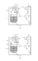
図2(a)は、後述するクリーニングブレード29が弾性変形していない場合のクリーニングブレード29の取り付け位置を説明した仮想断面図であり、図2(b)は、ベルトクリーニング手段20の構成を説明する概略断面図である。
[Belt cleaning means 20]
FIG. 2(a) is a virtual cross-sectional view for explaining the mounting position of the cleaning blade 29 when the cleaning blade 29 is not elastically deformed, and FIG. 2(b) is for explaining the structure of the belt cleaning means 20. FIG. It is a schematic cross-sectional view.

ベルトクリーニング手段20は、クリーニング容器27と、クリーニング容器27内に設けられたクリーニング作用部28と、を有する。クリーニング容器27は、中間転写ベルト13等を有する中間転写ユニット(不図示)の枠体の一部として構成されている。クリーニング作用部28は、クリーニング部材(当接部材)としてのクリーニングブレード29と、クリーニングブレード29を支持する支持部材30と、を有する。クリーニングブレード29は、弾性材料であるウレタンゴム(ポリウレタン)から構成される弾性ブレードであり、亜鉛メッキ鋼板を材料とする板金で形成された支持部材30に接着された状態で支持されている。 The belt cleaning means 20 has a cleaning container 27 and a cleaning acting portion 28 provided in the cleaning container 27 . The cleaning container 27 is configured as part of a frame of an intermediate transfer unit (not shown) having the intermediate transfer belt 13 and the like. The cleaning action portion 28 has a cleaning blade 29 as a cleaning member (contact member) and a support member 30 that supports the cleaning blade 29 . The cleaning blade 29 is an elastic blade made of urethane rubber (polyurethane), which is an elastic material.

クリーニングブレード29は、中間転写ベルト13の移動方向(以下、ベルト搬送方向と称する)と交差する中間転写ベルト13の幅方向(クリーニングブレード29の長手方向)に関して長い板状部材である。また、クリーニングブレード29は、短手方向に関して、自由端側の端部29aを中間転写ベルト13に対して当接されており、固定端側の端部29bを支持部材30に対して接着された状態で固定されている。このクリーニングブレード29の長手方向の長さは240mmであり、厚さは2.0mmであり、クリーニングブレード29の硬度はJIS K 6253規格で77°である。 The cleaning blade 29 is a plate-like member elongated in the width direction of the intermediate transfer belt 13 (longitudinal direction of the cleaning blade 29) intersecting the moving direction of the intermediate transfer belt 13 (hereinafter referred to as belt conveying direction). The cleaning blade 29 has a free end 29a in contact with the intermediate transfer belt 13 and a fixed end 29b bonded to the support member 30 in the lateral direction. status is fixed. The length of the cleaning blade 29 in the longitudinal direction is 240 mm, the thickness is 2.0 mm, and the hardness of the cleaning blade 29 is 77° according to the JIS K 6253 standard.

クリーニング作用部28は、中間転写ベルト13の表面に対して揺動可能に構成されている。すなわち、支持部材30は、クリーニング容器27に固定された揺動軸32を介して、中間転写ベルト13の表面に対して揺動可能に支持されている。クリーニング容器27内に設けられた付勢手段として加圧バネ34によって支持部材30が加圧されることで、揺動軸32を中心としてクリーニング作用部28が可動し、クリーニングブレード29が中間転写ベルト13に付勢(押圧)される。 The cleaning action portion 28 is configured to be swingable with respect to the surface of the intermediate transfer belt 13 . That is, the support member 30 is supported to be swingable with respect to the surface of the intermediate transfer belt 13 via a swing shaft 32 fixed to the cleaning container 27 . The support member 30 is pressurized by a pressure spring 34 as a biasing means provided in the cleaning container 27, so that the cleaning action portion 28 moves about the swing shaft 32, and the cleaning blade 29 moves toward the intermediate transfer belt. 13 is biased (pressed).

クリーニングブレード29に対向して、中間転写ベルト13の内周側には、張架ローラ15が配置されている。クリーニングブレード29は、張架ローラ15に対向する位置で、ベルト搬送方向に対してカウンター方向で中間転写ベルト13の表面に当接されている。すなわち、クリーニングブレード29は、その短手方向における自由端側の端部29aがベルト搬送方向に関する上流側を向くようにして、中間転写ベルト13の表面に当接されている。これにより、図2(b)に示すように、クリーニングブレード29と中間転写ベルト13との間にブレードニップ部33(当接部)が形成されている。クリーニングブレード29は、ブレードニップ部33において、移動する中間転写ベルト13の表面から転写残トナーを掻き取り、クリーニング容器27に回収する。 A tension roller 15 is arranged on the inner peripheral side of the intermediate transfer belt 13 so as to face the cleaning blade 29 . The cleaning blade 29 is in contact with the surface of the intermediate transfer belt 13 in the counter direction with respect to the belt conveying direction at a position facing the tension roller 15 . That is, the cleaning blade 29 is brought into contact with the surface of the intermediate transfer belt 13 so that the free end portion 29a in the width direction of the cleaning blade 29 faces the upstream side in the belt conveying direction. Thereby, as shown in FIG. 2B, a blade nip portion 33 (contact portion) is formed between the cleaning blade 29 and the intermediate transfer belt 13 . The cleaning blade 29 scrapes off transfer residual toner from the surface of the moving intermediate transfer belt 13 at the blade nip portion 33 and collects it in the cleaning container 27 .

本実施例では、クリーニングブレード29の取り付け位置は、次のように設定されている。図2(a)に示すように、設定角θが22°、侵入量δが1.45mm、当接圧が5.5N/mmである。ここで、設定角θは、中間転写ベルト13とクリーニングブレード29(より詳細にはその自由端側の端面)との交点における張架ローラ15の接線と、クリーニングブレード29(より詳細にはその厚さ方向に略直交する一方の表面)とがなす角度である。また、侵入量δは、クリーニングブレード29が張架ローラ15に対して重なる厚さ方向の長さである。また、当接圧は、ブレードニップ部33におけるクリーニングブレード29からの押圧力(長手方向における線圧)で定義され、フィルム式加圧力測定システム(商品名:PINCH,ニッタ社製)を用いて測定される。このように設定することで、高温高湿環境(室温30℃、湿度80%)でのクリーニングブレード29の捲れやスリップ音を抑制でき、良好なクリーニング性能を得ることができる。また、このように設定することで、低温低湿環境(室温15℃、湿度10%)でのクリーニング不良を抑制して、良好なクリーニング性能を得ることができる。 In this embodiment, the mounting position of the cleaning blade 29 is set as follows. As shown in FIG. 2(a), the set angle θ is 22°, the penetration amount δ is 1.45 mm, and the contact pressure is 5.5 N/mm. Here, the set angle .theta. one surface that is substantially perpendicular to the vertical direction). The penetration amount δ is the length of the cleaning blade 29 overlapping the tension roller 15 in the thickness direction. The contact pressure is defined by the pressing force (linear pressure in the longitudinal direction) from the cleaning blade 29 at the blade nip portion 33, and is measured using a film-type pressure measuring system (trade name: PINCH, manufactured by Nitta Co., Ltd.). be done. By setting in this way, it is possible to suppress curling and slip noise of the cleaning blade 29 in a high-temperature and high-humidity environment (room temperature 30° C., humidity 80%), and obtain good cleaning performance. In addition, by setting in this way, poor cleaning can be suppressed in a low-temperature and low-humidity environment (room temperature 15° C., humidity 10%), and good cleaning performance can be obtained.

また、中間転写ベルト13及びクリーニングブレード29が新品時の場合、ブレードニップ部33にはトナーが存在しておらず摩擦抵抗が大きくなる傾向にある。この摩擦抵抗が大きくなると、カウンター方向で中間転写ベルト13に対して当接しているクリーニングブレード29が、ベルト搬送方向に沿って当接した状態になってしまう現象(捲れ)や、スリップ音などの異音が発生するおそれがある。捲れが発生した場合、クリーニングブレード29によって中間転写ベルト13に残留したトナーをせき止めることが困難になることで、クリーニング不良が発生してしまうおそれがある。 Further, when the intermediate transfer belt 13 and the cleaning blade 29 are new, there is no toner in the blade nip portion 33 and the frictional resistance tends to increase. When this frictional resistance increases, the cleaning blade 29, which is in contact with the intermediate transfer belt 13 in the counter direction, is brought into contact with the intermediate transfer belt 13 in the belt conveying direction (curling), and slip noise occurs. Abnormal noise may occur. When curling occurs, it becomes difficult for the cleaning blade 29 to dam up the toner remaining on the intermediate transfer belt 13, which may result in defective cleaning.

そこで、本実施例の画像形成装置100は、画像形成を行う前の新品のクリーニングブレード29の端部29aに初期潤滑剤としてフッ化黒鉛(セフボンCMA:セントラル硝子社製)を塗布する構成としている。即ち、中間転写ベルト13及びクリーニングブレード29が新品の時は、フッ化黒鉛が潤滑剤としての機能を果たし、画像形成が開始された後においては、各現像手段4から供給されたトナーが潤滑剤としての機能を果たす。これにより、ブレードニップ部33において摩擦抵抗が大きくなることを抑制し、クリーニングブレード29の捲れや異音の発生を抑制できる。 Therefore, the image forming apparatus 100 of this embodiment is configured to apply graphite fluoride (Cefbon CMA: manufactured by Central Glass Co., Ltd.) as an initial lubricant to the end portion 29a of the new cleaning blade 29 before image formation. . That is, when the intermediate transfer belt 13 and the cleaning blade 29 are new, graphite fluoride functions as a lubricant, and after image formation is started, the toner supplied from each developing means 4 acts as a lubricant. function as As a result, it is possible to suppress an increase in frictional resistance at the blade nip portion 33, thereby suppressing curling of the cleaning blade 29 and generation of abnormal noise.

なお、中間転写ベルト13の材料などに応じて適宜選定されるものであるが、クリーニングブレード29のゴム硬度は、JIS K 6253規格で70°以上、且つ80°以下の範囲が好ましい。ゴム硬度が上記範囲よりも低いと、使用によるクリーニングブレード29の端部29aの摩耗量が増加して、耐久性が低下することがあり、上記範囲よりも高いと弾性力が減少して、中間転写ベルト13との摩擦により欠けなどが発生することがある。 The rubber hardness of the cleaning blade 29 is preferably in the range of 70° or more and 80° or less according to the JIS K 6253 standard, although it is appropriately selected according to the material of the intermediate transfer belt 13 and the like. If the rubber hardness is lower than the above range, the wear amount of the end portion 29a of the cleaning blade 29 increases due to use, and durability may decrease. Chipping or the like may occur due to friction with the transfer belt 13 .

また、中間転写ベルト13の材料などに応じて適宜選定されるものであるが、クリーニングブレード29の当接圧は、4.0N/mm以上、7.0N/mm以下の範囲が好ましい。当接圧が上記範囲よりも小さいと、良好なクリーニング性能が得られないことがあり、上記範囲よりも大きいと中間転写ベルト13を回転駆動するための負荷が大きくなりすぎることがある。 The contact pressure of the cleaning blade 29 is preferably in the range of 4.0 N/mm or more and 7.0 N/mm or less. If the contact pressure is smaller than the above range, good cleaning performance may not be obtained, and if it is larger than the above range, the load for rotating the intermediate transfer belt 13 may become too large.

[画像形成装置の駆動構成]
図3は、本実施例における、各感光ドラム1及び中間転写ベルト13の駆動構成を説明する模式図である。図3に示すように、本実施例においては、第1駆動源としてのモータM1によって、カートリッジ9dに駆動力を伝達して感光ドラム1dを回転駆動させ、且つ、中間転写ベルト13を回転駆動させている。また、第2駆動源としてのモータM2によって、各カートリッジ9a~9cに駆動力を伝達して感光ドラム1a~1cを回転駆動させている。この構成により、感光ドラム1a~1dと中間転写ベルト13とをそれぞれ別々のモータで駆動する構成に比べて、モータの個数を5個から2個に削減することが可能となる。
[Driving Configuration of Image Forming Apparatus]
FIG. 3 is a schematic diagram for explaining the drive configuration of each photosensitive drum 1 and intermediate transfer belt 13 in this embodiment. As shown in FIG. 3, in this embodiment, a driving force is transmitted to the cartridge 9d by a motor M1 as a first driving source to rotate the photosensitive drum 1d and to rotate the intermediate transfer belt 13. ing. A motor M2 as a second drive source transmits driving force to each of the cartridges 9a to 9c to rotationally drive the photosensitive drums 1a to 1c. With this configuration, the number of motors can be reduced from five to two compared to a configuration in which the photosensitive drums 1a to 1d and the intermediate transfer belt 13 are driven by separate motors.

また、本実施例においては、感光ドラム1dの回転軸に固定された不図示のギアと、現像ローラ41dの回転軸に固定された不図示のギアと、を連結することにより、モータM1からの駆動力を現像手段4dに伝達する構成としている。即ち、感光ドラム1dが回転駆動されることで、現像手段4dにおいて、現像ローラ41d、供給ローラ43d、そして後に説明する撹拌部材11dがそれぞれ回転する。 Further, in this embodiment, by connecting a gear (not shown) fixed to the rotation shaft of the photosensitive drum 1d and a gear (not shown) fixed to the rotation shaft of the developing roller 41d, The driving force is transmitted to the developing means 4d. That is, when the photosensitive drum 1d is driven to rotate, the developing roller 41d, the supply roller 43d, and the stirring member 11d, which will be described later, rotate in the developing means 4d.

[カートリッジ9]
次に、本実施例におけるカートリッジ9a~9dの構成について、カートリッジ9aを用いて説明する。図4(a)は、カートリッジ9dを長手方向(回転軸線方向)から見た概略断面図である。図4(b)は、カートリッジ9aの新品時における、長手方向(回転軸線方向)から見た概略断面図である。
[Cartridge 9]
Next, the configuration of the cartridges 9a to 9d in this embodiment will be described using the cartridge 9a. FIG. 4(a) is a schematic cross-sectional view of the cartridge 9d viewed from the longitudinal direction (rotational axis direction). FIG. 4(b) is a schematic cross-sectional view of the cartridge 9a when it is new, viewed from the longitudinal direction (rotational axis direction).

図4(a)に示すように、現像手段4aは、現像ローラ41a、供給ローラ43a、現像ブレード44a、開口45a、トナーを収容する収容室46a、トナー収容室の上部に設けられ、現像ローラ41aと供給ローラ43aを格納する現像室47a、を有する。本実施例においては、トナーは、正規の極性として負極性に帯電し、粒径が7μmである非磁性球形トナーを用いた。またトナーの表面には、トナー外添剤として粒径20nmのシリカ粒子(外添粒子)が添加されている。 As shown in FIG. 4A, the developing means 4a includes a developing roller 41a, a supply roller 43a, a developing blade 44a, an opening 45a, a storage chamber 46a for storing toner, and a toner storage chamber provided above the developing roller 41a. and a developing chamber 47a in which the supply roller 43a is housed. In this embodiment, the toner used is a non-magnetic spherical toner which is negatively charged as a normal polarity and has a particle size of 7 μm. Silica particles (external additive particles) having a particle size of 20 nm are added to the surface of the toner as a toner external additive.

現像ブレード44aは現像ローラ41aの回転方向(図示矢印R4方向)に対してカウンター方向に当接しており、供給ローラ43aによって供給されたトナーのコート量規制及び電荷付与を行っている。現像ブレード44aは薄い板状部材からなり、薄板のバネ弾性を利用して当接圧力を形成し、その表面がトナー及び現像ローラ41aに接触当接される。本実施例では、現像ブレード44aとして、厚さ0.1mmの板バネ状のSUS製の薄板に半導電性樹脂をコーティングしたものを用いた。また、現像ブレード44aは、薄板のバネ弾性を利用して当接圧力を形成することで、現像ブレード44aの表面を現像ローラ41aに担持されたトナーに接触させる構成とした。 The developing blade 44a is in contact with the developing roller 41a in a direction counter to the direction of rotation of the developing roller 41a (direction of arrow R4 in the figure), and controls the coating amount of the toner supplied by the supply roller 43a and applies charge. The developing blade 44a is made of a thin plate-like member, and uses the spring elasticity of the thin plate to form contact pressure, and the surface of the developing blade 44a is brought into contact with the toner and the developing roller 41a. In this embodiment, as the developing blade 44a, a 0.1 mm-thick leaf-spring-shaped SUS thin plate coated with a semi-conductive resin is used. Further, the development blade 44a is configured to contact the surface of the development blade 44a with the toner carried by the development roller 41a by forming contact pressure using the spring elasticity of the thin plate.

現像ブレード44aには、現像ブレード電源81から所定の電圧が印加される。これにより、トナーは現像ブレード44aと現像ローラ41a間の放電、及び現像ブレード44aと現像ローラ41aとの摺擦による摩擦帯電によって、マイナス電荷を付与されると同時に層厚を規制される。なお、本実施例においては、画像形成中では現像ローラ41aの電位に対する現像ブレード44aの電位差がΔV=-100Vとなるように、現像ブレード電源81から出力する電圧を制御している。 A predetermined voltage is applied from a developing blade power supply 81 to the developing blade 44a. As a result, the toner is negatively charged and its layer thickness is regulated by the discharge between the developing blade 44a and the developing roller 41a and the triboelectrification caused by the friction between the developing blade 44a and the developing roller 41a. In this embodiment, the voltage output from the developing blade power supply 81 is controlled so that the potential difference of the developing blade 44a with respect to the potential of the developing roller 41a is ΔV=-100V during image formation.

なお、現像ローラ41aは新品時に初期潤滑剤として、粒径が2μmのシリコーン粒子(トスパール120:モメンティブ・パフォーマンス・マテリアル社製)が塗布されている。これにより、新品時に現像ローラ41aと現像ブレード44aとの間に発生する摩擦力を低減させて、現像ブレード44aの変形(捲れ)の発生を抑制することができる。画像形成が実行された以降においては、現像ローラ41aと現像ブレード44aとの間にトナーが介在することで摩擦力を一定以下に保つことができる。したがって、新品時に現像ローラ41aに塗布されたシリコーン粒子は、新品のカートリッジ9aが画像形成装置100の装置本体に装着されたあとに実行される、画像形成の準備動作時に現像ローラ41aから除去される。なお、本実施例においては、初期塗布剤としてシリコーン粒子を用いたが、これに限らず、潤滑性、耐環境性を有するものであれば、新品時に現像ローラ41aにトナーを塗布する構成としてもよい。 When the developing roller 41a is new, silicone particles (Tospearl 120, manufactured by Momentive Performance Materials Co., Ltd.) having a particle size of 2 μm are applied as an initial lubricant to the developing roller 41a. As a result, it is possible to reduce the frictional force generated between the developing roller 41a and the developing blade 44a when the developing roller 41a is new, thereby suppressing the occurrence of deformation (curling) of the developing blade 44a. After the image formation is performed, the toner intervenes between the developing roller 41a and the developing blade 44a, so that the frictional force can be kept below a certain level. Therefore, the silicone particles applied to the developing roller 41a when new are removed from the developing roller 41a during the preparatory operation for image formation, which is executed after the new cartridge 9a is installed in the main body of the image forming apparatus 100. . In this embodiment, silicone particles are used as the initial coating agent, but the present invention is not limited to this, as long as it has lubricity and environmental resistance, the toner may be applied to the developing roller 41a when the roller is new. good.

供給ローラ43aは、現像ローラ41aの周面上に所定のニップ部を形成して配設されており、図示矢印R5方向に回転する。供給ローラ43aは導電性芯金の外周に発泡体を形成した弾性スポンジローラである。供給ローラ43aと現像ローラ41aは所定の侵入量を持って接触し、接触部Ndを形成している。本実施例においては、現像ローラ41a、供給ローラ43aは、共に外径φ20であり、供給ローラ43aの現像ローラ41aへの侵入量を1.5mmに設定した。 The supply roller 43a is disposed on the peripheral surface of the developing roller 41a so as to form a predetermined nip portion, and rotates in the illustrated arrow R5 direction. The supply roller 43a is an elastic sponge roller in which a foam is formed on the outer periphery of a conductive core. The supply roller 43a and the development roller 41a are in contact with each other with a predetermined penetration amount to form a contact portion Nd. In this embodiment, the developing roller 41a and the supply roller 43a both have an outer diameter of φ20, and the penetration amount of the supply roller 43a into the developing roller 41a is set to 1.5 mm.

また、供給ローラ43aと現像ローラ41aは接触部Ndにおいて互いに逆方向に移動するよう回転している。この動作により、供給ローラ43aによる現像ローラ41aへのトナー供給及び現像残として残った現像ローラ41a上のトナーの剥ぎ取りを行っている。この時、供給ローラ43aに対して現像ローラ41aとの電位差を調整することにより、現像ローラ41aへのトナー供給量を調整することが出来る。本実施例では、供給ローラ43aの電位に対して現像ローラ41aの電位がΔV=+50Vとなるように、供給ローラ電源82から供給ローラ43aに対して印加する電圧(直流電圧)の値を設定している。 Further, the supply roller 43a and the development roller 41a rotate so as to move in opposite directions at the contact portion Nd. By this operation, the toner is supplied to the developing roller 41a by the supply roller 43a, and the toner remaining on the developing roller 41a as development residue is stripped off. At this time, the amount of toner supplied to the developing roller 41a can be adjusted by adjusting the potential difference between the supply roller 43a and the developing roller 41a. In this embodiment, the value of the voltage (DC voltage) applied from the supply roller power supply 82 to the supply roller 43a is set so that the potential of the developing roller 41a becomes ΔV=+50 V with respect to the potential of the supply roller 43a. ing.

収容室46a内には撹拌部材11a(除去部材)が設けられている。撹拌部材11aは、収容室46a内に収納されたトナーを攪拌すると共に、供給ローラ43aの上部に向けて、開口45aから図中矢印G方向にトナーを搬送する。 A stirring member 11a (removing member) is provided in the storage chamber 46a. The agitating member 11a agitates the toner stored in the storage chamber 46a and conveys the toner from the opening 45a toward the upper portion of the supply roller 43a in the direction of arrow G in the drawing.

現像ローラ41aと感光ドラム1aとが当接する位置(以下、現像部Ngと称する)において、現像ローラ41aと感光ドラム1aは、互いの表面が同一方向に移動するように、それぞれ回転駆動される。画像形成時においては、現像ローラ電源80から現像ローラ41aに感光ドラム1aの帯電極性(本実施例では負極性)と同極性の直流電圧が印加される。これにより、現像部Ngにおいて、現像ローラ41aに担持された負極性に帯電したトナーが感光ドラム1aの静電潜像部に移動し、静電潜像を現像してトナー像を形成する。 At a position where the developing roller 41a and the photosensitive drum 1a contact each other (hereinafter referred to as a developing portion Ng), the developing roller 41a and the photosensitive drum 1a are rotationally driven so that their surfaces move in the same direction. During image formation, a DC voltage having the same polarity as the charging polarity (negative polarity in this embodiment) of the photosensitive drum 1a is applied from the developing roller power source 80 to the developing roller 41a. As a result, in the developing portion Ng, the negatively charged toner carried on the developing roller 41a moves to the electrostatic latent image portion of the photosensitive drum 1a, and develops the electrostatic latent image to form a toner image.

<封止部材の開封動作>
図4(b)に示すように、カートリッジ9aが新品の時においては、現像ローラ41aと供給ローラ43aが設けられた現像室47aと、トナーを収容する収容室46aと、が封止部材48aにより区分されている。これは、ユーザーがカートリッジの使用を開始するまでの間に、収容室46aからトナーが漏れることを抑制するためである。
<Opening operation of sealing member>
As shown in FIG. 4B, when the cartridge 9a is new, the developing chamber 47a in which the developing roller 41a and the supply roller 43a are provided, and the storage chamber 46a for storing the toner are separated by the sealing member 48a. are divided. This is to prevent the toner from leaking from the housing chamber 46a until the user starts using the cartridge.

図4(b)に示すように、封止部材48aの一端部は開口45aを封止するように、開口45aの周縁部に剥離可能に固定される。他端部は、撹拌部材11aの一端に固定される。ユーザーが新品のカートリッジ9aの使用を開始すると、モータM2からの駆動力を受けることで、収容室46aに設けられる撹拌部材11aが図4中における時計方向に回転する。この撹拌部材11aの回転により、封止部材48aは開口45aの周縁部から剥離され、開口45aが開封される。そして、時計方向に回転する撹拌部材11aにより収容室46aから現像室47aへトナーを搬送することが可能となる。なお、封止部材48aの固定方法は、本実施例ではヒートシール方式を用いたが、これに限らず、他に、超音波溶着や両面テープ等の固定方法を用いても良い。 As shown in FIG. 4B, one end of the sealing member 48a is detachably fixed to the periphery of the opening 45a so as to seal the opening 45a. The other end is fixed to one end of the stirring member 11a. When the user starts using the new cartridge 9a, the stirring member 11a provided in the storage chamber 46a rotates clockwise in FIG. 4 by receiving the driving force from the motor M2. Due to this rotation of the stirring member 11a, the sealing member 48a is peeled off from the periphery of the opening 45a, and the opening 45a is unsealed. Then, the toner can be conveyed from the storage chamber 46a to the developing chamber 47a by the stirring member 11a that rotates clockwise. In this embodiment, the heat sealing method is used to fix the sealing member 48a, but it is not limited to this, and other fixing methods such as ultrasonic welding and double-sided tape may be used.

[カートリッジの準備動作]
本実施例では、画像形成装置100の装置本体に装着されたカートリッジが新品か否かを、各カートリッジ9に具備された不揮発性の記憶手段(以下、メモリと称す)の検知結果から判断する。図1に示すように、各カートリッジ9には、メモリと、メモリへの情報の読み書きを制御するための伝達部とが一体化された基板91が設けられている。また、画像形成装置100の本体には、各カートリッジ9の伝達部からの情報をCPU102に設けられる記憶部に伝達する伝達部(不図示)が設けられている。
[Cartridge preparation operation]
In this embodiment, whether or not the cartridges mounted in the main body of the image forming apparatus 100 are new is determined from the detection results of non-volatile storage means (hereinafter referred to as memory) provided in each cartridge 9 . As shown in FIG. 1, each cartridge 9 is provided with a substrate 91 integrating a memory and a transmission section for controlling reading and writing of information to and from the memory. Further, the main body of the image forming apparatus 100 is provided with a transmission section (not shown) for transmitting information from the transmission section of each cartridge 9 to a storage section provided in the CPU 102 .

本実施例においては、カートリッジが画像形成装置100に装着されると、各カートリッジ9側の基板91と画像形成装置100側の伝達部とが対面して接触した状態になる。これにより、制御基板101に設けられるCPU102と、各カートリッジ9のメモリが電気的に接続された状態となり、CPU102によって、メモリに記録された情報の読み込みやメモリに対する情報の書込みを実行することが可能となる。 In this embodiment, when the cartridges are attached to the image forming apparatus 100, the board 91 on the side of each cartridge 9 and the transmission section on the side of the image forming apparatus 100 face each other and come into contact with each other. As a result, the CPU 102 provided on the control board 101 and the memory of each cartridge 9 are electrically connected, and the CPU 102 can read information recorded in the memory and write information to the memory. becomes.

なお、メモリとしては、通常の半導体による電子的なメモリが特に制限なく使用することができる。また、本実施例においては、カートリッジが画像形成装置100に装着された場合に、各カートリッジ9側の基板91と画像形成装置100側の伝達部とが対面して接触した状態になる構成について説明した。しかし、これに限らず、カートリッジが画像形成装置100に装着された場合に、各カートリッジ9側の基板91と画像形成装置100側の伝達部とを接触させず、近距離通信などを用いてCPU102によるメモリへの情報の読み書きを実行してもよい。 As the memory, an electronic memory made of ordinary semiconductors can be used without particular limitation. Also, in this embodiment, when the cartridges are installed in the image forming apparatus 100, the substrate 91 on the side of each cartridge 9 and the transmission section on the side of the image forming apparatus 100 face each other and are in contact with each other. did. However, the present invention is not limited to this, and when the cartridges are attached to the image forming apparatus 100, the substrate 91 on the side of each cartridge 9 and the transmission section on the side of the image forming apparatus 100 are not brought into contact with each other, and the CPU 102 is controlled by short-distance communication or the like. may read and write information to memory.

本実施例の画像形成装置100においては、装置本体に新品のカートリッジが装着された場合に、新品のカートリッジの現像手段4における封止部材48の除去動作を含む画像形成動作を行うための準備動作が実行される。図5は、画像形成装置100の装置本体に新品のカートリッジが装着された場合に実行される制御を説明するフローチャートである。 In the image forming apparatus 100 of this embodiment, when a new cartridge is installed in the main body of the apparatus, a preparatory operation for performing an image forming operation including an operation of removing the sealing member 48 in the developing means 4 of the new cartridge. is executed. FIG. 5 is a flowchart for explaining control executed when a new cartridge is installed in the main body of image forming apparatus 100 .

図5に示すように、まず、制御手段としてのCPU102は、各カートリッジ9のメモリの情報を読み込み、中間転写ベルト13と共通の駆動源であるモータM1によって駆動されるカートリッジ9dが新品か否かを検知する(ステップS1)。カートリッジ9dが新品であると検知された場合は、次にモータM2によって駆動されるカートリッジ9a~9cのうちいずれかのカートリッジが新品か否かを検知する(ステップS2)。なお、ステップS1でカートリッジ9dが新品でないと検知された場合であっても、ステップS2と同様の検知をステップS3で行う。 As shown in FIG. 5, first, the CPU 102 as a control means reads the information in the memory of each cartridge 9 and determines whether or not the cartridge 9d driven by the motor M1, which is a drive source common to the intermediate transfer belt 13, is new. is detected (step S1). If the cartridge 9d is detected to be new, then it is detected whether or not any one of the cartridges 9a to 9c driven by the motor M2 is new (step S2). Note that even if it is detected in step S1 that the cartridge 9d is not new, the same detection as in step S2 is performed in step S3.

ステップS2でカートリッジ9a~9cのうちいずれかのカートリッジが新品であると検知された場合は、第1の準備動作を実行する(ステップS4)。一方、ステップS2でカートリッジ9a~9cのいずれのカートリッジも新品ではないと検知された場合は、第2の準備動作を実行する(ステップS5)。また、ステップS3でカートリッジ9a~9cのうちいずれかのカートリッジが新品であると検知された場合は、第3の準備動作を実行する(ステップS6)。そして、各ステップS4~S6における準備動作が実行された後に、CPU102は、画像形成装置100が画像形成可能な状態であると判断する(ステップS8)。 If any one of the cartridges 9a to 9c is detected to be new in step S2, a first preparatory operation is executed (step S4). On the other hand, if it is detected in step S2 that none of the cartridges 9a to 9c are new, a second preparatory operation is executed (step S5). Further, when any one of the cartridges 9a to 9c is detected to be new in step S3, a third preparatory operation is executed (step S6). After the preparatory operations in steps S4 to S6 are executed, CPU 102 determines that image forming apparatus 100 is ready for image formation (step S8).

なお、ステップS3でカートリッジ9a~9cのいずれのカートリッジも新品ではないと検知された場合は、CPU102は、全てのカートリッジ9a~9dが新品でないと判断する。そして、画像形成を行うための前述の第1~第3のいずれの準備動作も実行せず、ステップ8へと進む。図5に示すように、本実施例においては、いずれのカートリッジ9が装着されたかで、CPU102によって実行される準備動作が異なる。以下、図6(a)~(c)を用いて、第1~第3の準備動作について詳細に述べる。 If none of the cartridges 9a to 9c are found to be new in step S3, the CPU 102 determines that none of the cartridges 9a to 9d are new. Then, the process proceeds to step 8 without executing any of the first to third preparatory operations for image formation. As shown in FIG. 5, in this embodiment, the preparatory operation executed by the CPU 102 differs depending on which cartridge 9 is loaded. The first to third preparatory operations will be described in detail below with reference to FIGS. 6(a) to 6(c).

<第1の準備動作>
図6(a)は、第1の準備動作のフローを説明するフローチャートである。第1の準備動作は、カートリッジ9dが新品で、かつ、カートリッジ9a~9cのうち少なくとも1つ以上のカートリッジが新品であることをCPU102が検知した場合に実行される準備動作である。
<First preparation operation>
FIG. 6A is a flowchart for explaining the flow of the first preparatory operation. The first preparatory operation is executed when the CPU 102 detects that the cartridge 9d is new and at least one of the cartridges 9a to 9c is new.

図6(a)に示すように、まず、CPU102は、ステップS101において、カートリッジ9a~9cの各種部材に駆動を伝達するモータM2の駆動を開始する。この時、各感光ドラム1a~1dは中間転写ベルト13に対して離間させている。そして、ステップS102において、カートリッジ9a~9cの各種部材(帯電ローラ2a~2c、現像ローラ41a~41c、供給ローラ43a~43c、現像ブレード44a~44c)への電圧印加を開始する。本実施例では、帯電ローラ2a~2cに-1000V、現像ローラ41a~41cに-300V、供給ローラ43a~43cに-350V、現像ブレード44a~44cに-450Vの所定の電圧をそれぞれ印加した。 As shown in FIG. 6A, first, in step S101, the CPU 102 starts driving the motor M2 that transmits driving force to various members of the cartridges 9a to 9c. At this time, the photosensitive drums 1a to 1d are separated from the intermediate transfer belt 13. As shown in FIG. Then, in step S102, voltage application to various members of the cartridges 9a to 9c (charging rollers 2a to 2c, developing rollers 41a to 41c, supply rollers 43a to 43c, developing blades 44a to 44c) is started. In this embodiment, a predetermined voltage of -1000 V was applied to the charging rollers 2a to 2c, -300 V to the developing rollers 41a to 41c, -350 V to the supply rollers 43a to 43c, and -450 V to the developing blades 44a to 44c.

その後、ステップS103において、新品のカートリッジにおける画像形成を行う準備動作が完了するまでの間、前述の所定の電圧を印加した状態で、カートリッジ9a~9cの各種部材を回転駆動させる。ここで、新品のカートリッジにおける画像形成を行う準備動作とは、封止部材48の剥離と、現像室47へのトナーの供給と、供給ローラ43から現像ローラ41へのトナーの供給の動作を指す。 After that, in step S103, various members of the cartridges 9a to 9c are rotationally driven while the predetermined voltage is applied until the preparatory operation for image formation in the new cartridge is completed. Here, the preparatory operation for image formation in a new cartridge refers to the operation of peeling off the sealing member 48, supplying toner to the developing chamber 47, and supplying toner from the supply roller 43 to the developing roller 41. .

ステップ104においては、現像ローラ41a~41cから感光ドラム1a~1cに設けられたクリーニングブレード31a~31cに対して、潤滑剤としてのトナーを供給する。トナーの供給を行う場合、CPU102は、まず、露光手段12a~12cからの走査ビームにより、帯電ローラ2a~2cによって帯電された感光ドラム1a~1cの表面に静電潜像を形成する。この時、感光ドラム1の回転方向(図1における矢印R1方向)に関して現像ローラ41の1周分の長さであって、感光ドラム1の長手方向に関して画像を形成可能な最大幅の静電潜像を形成する。その後、この静電潜像を現像ローラ41a~41cに担持されたトナーによって現像し、感光ドラム1a~1cにドラム供給用トナー像を形成する。なお、本実施例におけるクリーニングブレード31a~31cへのトナーの供給動作では、前述のドラム供給用トナー像を一定間隔ごとに計40回形成する。これらのドラム供給用トナー像は、感光ドラム1の回転に伴ってクリーニングブレード31に到達し、クリーニングブレード31と感光ドラム1とが当接する位置において潤滑剤として機能する。 In step 104, toner as a lubricant is supplied from the developing rollers 41a to 41c to the cleaning blades 31a to 31c provided on the photosensitive drums 1a to 1c. When supplying toner, the CPU 102 first forms electrostatic latent images on the surfaces of the photosensitive drums 1a to 1c charged by the charging rollers 2a to 2c by scanning beams from the exposure means 12a to 12c. At this time, the maximum width of the electrostatic latent image that can form an image in the longitudinal direction of the photosensitive drum 1, which is the length of one rotation of the developing roller 41 in the direction of rotation of the photosensitive drum 1 (the direction of arrow R1 in FIG. 1). form an image. After that, the electrostatic latent image is developed with the toner carried on the developing rollers 41a to 41c to form the toner image for drum supply on the photosensitive drums 1a to 1c. In the operation of supplying toner to the cleaning blades 31a to 31c in this embodiment, the toner image for drum supply is formed 40 times in total at regular intervals. These drum-supply toner images reach the cleaning blade 31 as the photosensitive drum 1 rotates, and function as a lubricant at the position where the cleaning blade 31 and the photosensitive drum 1 contact each other.

続いて、ステップS105において、感光ドラム1a~1dと中間転写ベルト13とを当接させ、ステップS106において、カートリッジ9dの各種部材及び中間転写ベルト13に駆動を伝達するモータM1の駆動を開始する。 Subsequently, in step S105, the photosensitive drums 1a to 1d and the intermediate transfer belt 13 are brought into contact with each other, and in step S106, driving of the motor M1 for transmitting drive to various members of the cartridge 9d and the intermediate transfer belt 13 is started.

そして、ステップS107において、カートリッジ9dの各種部材(帯電ローラ2d、現像ローラ41d、供給ローラ43d、現像ブレード44d)への電圧印加を開始する。本実施例では、帯電ローラ2dに-1000V、現像ローラ41dに-300V、供給ローラ43dに-350V、現像ブレード44dに-450Vの所定の電圧をそれぞれ印加した。 Then, in step S107, voltage application to various members of the cartridge 9d (charging roller 2d, developing roller 41d, supply roller 43d, developing blade 44d) is started. In this embodiment, a predetermined voltage of −1000 V was applied to the charging roller 2d, −300 V to the developing roller 41d, −350 V to the supply roller 43d, and −450 V to the developing blade 44d.

その後、ステップS108において、新品のカートリッジ9dにおける画像形成を行う準備動作が完了するまでの間、前述の所定の電圧を印加した状態で、カートリッジ9dの各種部材を回転駆動させる。ここで、新品のカートリッジ9dにおける画像形成を行う準備動作とは、封止部材48dの剥離と、現像室47dへのトナーの供給と、供給ローラ43dから現像ローラ41dへのトナーの供給の動作を指す。なお、ステップS108においては、カートリッジ9dにおける前述の準備動作の実行とともに、カートリッジ9a~9cから中間転写ベルト13にトナーを供給する。 After that, in step S108, various members of the cartridge 9d are rotated while the predetermined voltage is applied until the preparatory operation for image formation in the new cartridge 9d is completed. Here, the preparatory operation for image formation in the new cartridge 9d includes the operations of peeling off the sealing member 48d, supplying toner to the developing chamber 47d, and supplying toner from the supply roller 43d to the developing roller 41d. Point. In step S108, toner is supplied from the cartridges 9a to 9c to the intermediate transfer belt 13 along with the execution of the above-described preparatory operation in the cartridge 9d.

カートリッジ9a~9cから中間転写ベルト13にトナーを供給する動作は、以下のようにして行われる。まず、各感光ドラム1a~1cに、感光ドラム1の回転方向(図1における矢印R1方向)に関して現像ローラ41の2周分の長さであって、感光ドラム1の長手方向に関して画像を形成可能な最大幅のハーフトーン画像の静電潜像を形成する。その後、この静電潜像を、現像手段4a~4cの現像ローラ41a~41cに担持されたトナーによって現像し、感光ドラム1a~1cにベルト供給用トナー像を形成する。そして、各感光ドラム1a~1cに形成されたベルト供給用トナー像を各一次転写部N1a~N1cにおいて中間転写ベルト13に転写する。これらのベルト供給用トナー像は、中間転写ベルト13の移動に伴ってベルトクリーニング手段20に到達し、中間転写ベルト13とクリーニングブレード29とが当接するブレードニップ部33に供給され、潤滑剤として機能する。 The operation of supplying toner from the cartridges 9a to 9c to the intermediate transfer belt 13 is performed as follows. First, on each of the photosensitive drums 1a to 1c, an image can be formed in the longitudinal direction of the photosensitive drum 1 with a length corresponding to two turns of the developing roller 41 in the rotational direction of the photosensitive drum 1 (direction of arrow R1 in FIG. 1). forming an electrostatic latent image of a full width halftone image. After that, the electrostatic latent image is developed with the toner carried on the developing rollers 41a-41c of the developing means 4a-4c to form the toner image for belt supply on the photosensitive drums 1a-1c. Then, the toner images for belt supply formed on the photosensitive drums 1a to 1c are transferred to the intermediate transfer belt 13 at the primary transfer portions N1a to N1c. These belt-supplied toner images reach the belt cleaning means 20 as the intermediate transfer belt 13 moves, are supplied to the blade nip portion 33 where the intermediate transfer belt 13 and the cleaning blade 29 contact, and function as a lubricant. do.

その後、ステップS109において、感光ドラム1a~1dと中間転写ベルト13とを離間させた後に、ステップS110において、感光ドラム1dのクリーニングブレード31dにトナーを供給する。クリーニングブレード31dへのトナーの供給動作は、ステップS104でカートリッジ9a~9cにおいて実施したのと同様に、感光ドラム1dにドラム供給用トナー像を形成することによって実行される。これらのドラム供給用トナー像は、感光ドラム1dの回転に伴ってクリーニングブレード31dに到達し、クリーニングブレード31dと感光ドラム1dとが当接する位置において潤滑剤として機能する。 After that, in step S109, after the photosensitive drums 1a to 1d and the intermediate transfer belt 13 are separated, in step S110, toner is supplied to the cleaning blade 31d of the photosensitive drum 1d. The operation of supplying toner to the cleaning blade 31d is performed by forming a toner image for drum supply on the photosensitive drum 1d in the same manner as in step S104 for the cartridges 9a to 9c. These drum-supply toner images reach the cleaning blade 31d as the photosensitive drum 1d rotates, and function as a lubricant at the position where the cleaning blade 31d and the photosensitive drum 1d contact each other.

そして、ステップS110において、カートリッジ9a~9dの各種部材(帯電ローラ2a~2d、現像ローラ41a~41d、供給ローラ43a~43d、現像ブレード44a~44d)への電圧印加を停止する。その後、ステップS112において、モータM1とモータM2の駆動を停止し、第1の準備動作が完了する。 Then, in step S110, voltage application to various members of the cartridges 9a-9d (charging rollers 2a-2d, developing rollers 41a-41d, supply rollers 43a-43d, developing blades 44a-44d) is stopped. After that, in step S112, the driving of the motors M1 and M2 is stopped, and the first preparatory operation is completed.

なお、本実施例においては、ステップS103とステップS104でカートリッジ9a~9cすべてに関して各種動作を実行する構成について説明したが、これらの動作は、新品のカートリッジのみで実行されても良い。例えば、CPU102によって、カートリッジ9aのみが新品であると判断された場合、ステップS103及びステップS104の動作をカートリッジ9aのみにおいて実行する構成としても良く、カートリッジ9a~9cを連動させて実行する構成としても良い。 In the present embodiment, steps S103 and S104 have been described with respect to all the cartridges 9a to 9c, but these operations may be executed only for new cartridges. For example, when the CPU 102 determines that only the cartridge 9a is new, the operations of steps S103 and S104 may be executed only in the cartridge 9a, or may be executed in conjunction with the cartridges 9a to 9c. good.

また、本実施例においては、ステップS108において、カートリッジ9a~9cすべてに関してベルト供給用トナー像を形成する構成について説明したが、これに限らない。ブレードニップ部33に所定のトナーを供給することが可能であれば、カートリッジ9a~9cのいずれか1つ若しくは2つにおいて、ベルト供給用トナー像を形成する構成としても良い。 Further, in this embodiment, in step S108, the configuration for forming the belt-supply toner image for all the cartridges 9a to 9c has been described, but the present invention is not limited to this. If a predetermined toner can be supplied to the blade nip portion 33, the toner image for belt supply may be formed in one or two of the cartridges 9a to 9c.

<第2の準備動作>
図6(b)は、第2の準備動作のフローを説明するフローチャートである。第2の準備動作は、カートリッジ9dは新品だが、カートリッジ9a~9cは新品ではないことをCPU102が検知した場合に実行される準備動作である。
<Second preparatory operation>
FIG. 6B is a flowchart for explaining the flow of the second preparatory operation. The second preparatory operation is executed when the CPU 102 detects that the cartridge 9d is new but the cartridges 9a to 9c are not new.

図6(b)に示すように、まず、CPU102は、ステップS201において感光ドラム1a~1dと中間転写ベルト13とを当接させる。そして、ステップS202において、カートリッジ9dの各種部材及び中間転写ベルト13に駆動を伝達するモータM1と、カートリッジ9a~9cの各種部材に駆動を伝達するモータM2の駆動を開始する。 As shown in FIG. 6B, first, the CPU 102 brings the photosensitive drums 1a to 1d and the intermediate transfer belt 13 into contact with each other in step S201. Then, in step S202, the motor M1 for transmitting drive to various members of the cartridge 9d and the intermediate transfer belt 13 and the motor M2 for transmitting drive to various members of the cartridges 9a to 9c are started to be driven.

続いて、ステップS203において、カートリッジ9a~9dの各種部材(帯電ローラ2a~2d、現像ローラ41a~41d、供給ローラ43a~43d、現像ブレード44a~44d)への電圧印加を開始する。本実施例では、帯電ローラ2a~2dに-1000V、現像ローラ41a~41dに-300V、供給ローラ43a~43dに-350V、現像ブレード44a~44dに-450Vの所定の電圧をそれぞれ印加した。 Subsequently, in step S203, voltage application to various members of the cartridges 9a to 9d (charging rollers 2a to 2d, developing rollers 41a to 41d, supply rollers 43a to 43d, developing blades 44a to 44d) is started. In this embodiment, a predetermined voltage of -1000 V was applied to the charging rollers 2a to 2d, -300 V to the developing rollers 41a to 41d, -350 V to the supply rollers 43a to 43d, and -450 V to the developing blades 44a to 44d.

その後、ステップS204において、新品のカートリッジ9dにおける画像形成を行う準備動作が完了するまでの間、前述の所定の電圧を印加した状態で、カートリッジ9dの各種部材を回転駆動させる。ここで、新品のカートリッジ9dにおける画像形成を行う準備動作とは、封止部材48dの剥離と、現像室47dへのトナーの供給と、供給ローラ43dから現像ローラ41dへのトナーの供給の動作を指す。なお、ステップS204においては、カートリッジ9dにおける前述の準備動作の実行とともに、カートリッジ9a~9cから中間転写ベルト13にトナーを供給する。 After that, in step S204, various members of the cartridge 9d are rotated while the predetermined voltage is applied until the preparatory operation for image formation in the new cartridge 9d is completed. Here, the preparatory operation for image formation in the new cartridge 9d includes the operations of peeling off the sealing member 48d, supplying toner to the developing chamber 47d, and supplying toner from the supply roller 43d to the developing roller 41d. Point. In step S204, toner is supplied from the cartridges 9a to 9c to the intermediate transfer belt 13 along with the execution of the preparatory operation in the cartridge 9d.

カートリッジ9a~9cから中間転写ベルト13にトナーを供給する動作は、以下のようにして行われる。まず、各感光ドラム1a~1cに、感光ドラム1の回転方向(図1における矢印R1方向)に関して現像ローラ41の2周分の長さであって、感光ドラム1の長手方向に関して画像を形成可能な最大幅のハーフトーン画像の静電潜像を形成する。その後、この静電潜像を、現像手段4a~4cの現像ローラ41a~41cに担持されたトナーによって現像し、感光ドラム1a~1cにベルト供給用トナー像を形成する。そして、各感光ドラム1a~1cに形成されたベルト供給用トナー像を各一次転写部N1a~N1cにおいて中間転写ベルト13に転写する。これらのベルト供給用トナー像は、中間転写ベルト13の移動に伴ってベルトクリーニング手段20に到達し、中間転写ベルト13とクリーニングブレード29とが当接するブレードニップ部33に供給され、潤滑剤として機能する。 The operation of supplying toner from the cartridges 9a to 9c to the intermediate transfer belt 13 is performed as follows. First, on each of the photosensitive drums 1a to 1c, an image can be formed in the longitudinal direction of the photosensitive drum 1 with a length corresponding to two turns of the developing roller 41 in the rotational direction of the photosensitive drum 1 (direction of arrow R1 in FIG. 1). forming an electrostatic latent image of a full width halftone image. After that, the electrostatic latent image is developed with the toner carried on the developing rollers 41a-41c of the developing means 4a-4c to form the toner image for belt supply on the photosensitive drums 1a-1c. Then, the toner images for belt supply formed on the photosensitive drums 1a to 1c are transferred to the intermediate transfer belt 13 at the primary transfer portions N1a to N1c. These belt-supplied toner images reach the belt cleaning means 20 as the intermediate transfer belt 13 moves, are supplied to the blade nip portion 33 where the intermediate transfer belt 13 and the cleaning blade 29 contact, and function as a lubricant. do.

その後、ステップS205において、感光ドラム1a~1dと中間転写ベルト13とを離間させた後に、ステップS206において、感光ドラム1dのクリーニングブレード31dにトナーを供給する。クリーニングブレード31dへのトナーの供給動作を実行する場合、CPU102は、まず、露光手段12dからの走査ビームにより、帯電ローラ2dによって帯電された感光ドラム1dの表面に静電潜像を形成する。この時、感光ドラム1dの回転方向(図1における矢印R1方向)に関して現像ローラ41dの1周分の長さであって、感光ドラム1dの長手方向に関して画像を形成可能な最大幅の静電潜像を形成する。その後、この静電潜像を現像ローラ41dに担持されたトナーによって現像し、感光ドラム1dにドラム供給用トナー像を形成する。なお、本実施例におけるクリーニングブレード31dへのトナーの供給動作では、前述のドラム供給用トナー像を一定間隔ごとに計40回形成する。これらのドラム供給用トナー像は、感光ドラム1の回転に伴ってクリーニングブレード31dに到達し、クリーニングブレード31dと感光ドラム1とが当接する位置において潤滑剤として機能する。 After that, in step S205, the photosensitive drums 1a to 1d are separated from the intermediate transfer belt 13, and in step S206, toner is supplied to the cleaning blade 31d of the photosensitive drum 1d. When executing the operation of supplying toner to the cleaning blade 31d, the CPU 102 first forms an electrostatic latent image on the surface of the photosensitive drum 1d charged by the charging roller 2d with the scanning beam from the exposure means 12d. At this time, the maximum width of the electrostatic latent that can form an image in the longitudinal direction of the photosensitive drum 1d, which is the length of one rotation of the developing roller 41d in the rotational direction of the photosensitive drum 1d (direction of arrow R1 in FIG. 1). form an image. After that, the electrostatic latent image is developed with toner carried on the developing roller 41d to form a toner image for drum supply on the photosensitive drum 1d. In the operation of supplying toner to the cleaning blade 31d in this embodiment, the toner image for drum supply is formed 40 times in total at regular intervals. These drum-supply toner images reach the cleaning blade 31d as the photosensitive drum 1 rotates, and function as a lubricant at the position where the cleaning blade 31d and the photosensitive drum 1 contact each other.

そして、ステップS207において、カートリッジ9a~9dの各種部材(帯電ローラ2a~2d、現像ローラ41a~41d、供給ローラ43a~43d、現像ブレード44a~44d)への電圧印加を停止する。その後、ステップS208において、モータM1とモータM2の駆動を停止し、第2の準備動作を終了する。 Then, in step S207, voltage application to various members of the cartridges 9a-9d (charging rollers 2a-2d, developing rollers 41a-41d, supply rollers 43a-43d, developing blades 44a-44d) is stopped. After that, in step S208, the driving of the motors M1 and M2 is stopped, and the second preparatory operation ends.

なお、本実施例においては、ステップS204において、カートリッジ9a~9cすべてに関してベルト供給用トナー像を形成する構成について説明したが、これに限らない。ブレードニップ部33に所定のトナーを供給することが可能であれば、カートリッジ9a~9cのいずれか1つ若しくは2つにおいて、ベルト供給用トナー像を形成する構成としても良い。 In this embodiment, in step S204, the configuration for forming the belt-supply toner image for all the cartridges 9a to 9c has been described, but the present invention is not limited to this. If a predetermined toner can be supplied to the blade nip portion 33, the toner image for belt supply may be formed in one or two of the cartridges 9a to 9c.

<第3の準備動作>
図6(c)は、第3の準備動作のフローを説明するフローチャートである。第3の準備動作は、カートリッジ9dは新品ではないが、カートリッジ9a~9cのうち少なくとも1つ以上のカートリッジが新品であることをCPU102が検知した場合に実行される準備動作である。
<Third preparatory operation>
FIG. 6(c) is a flowchart for explaining the flow of the third preparatory operation. The third preparatory operation is performed when the CPU 102 detects that at least one of the cartridges 9a to 9c is new, although the cartridge 9d is not new.

図6(c)に示すように、まず、CPU102は、ステップS301において、カートリッジ9a~9cの各種部材に駆動を伝達するモータM2の駆動を開始する。この時、各感光ドラム1a~1dは中間転写ベルト13に対して離間させている。そして、ステップS302において、カートリッジ9a~9cの各種部材(帯電ローラ2a~2c、現像ローラ41a~41c、供給ローラ43a~43c、現像ブレード44a~44c)への電圧印加を開始する。本実施例では、帯電ローラ2a~2cに-1000V、現像ローラ41a~41cに-300V、供給ローラ43a~43cに-350V、現像ブレード44a~44cに-450Vの所定の電圧をそれぞれ印加した。 As shown in FIG. 6(c), first, in step S301, the CPU 102 starts driving the motor M2 that transmits drive to various members of the cartridges 9a to 9c. At this time, the photosensitive drums 1a to 1d are separated from the intermediate transfer belt 13. As shown in FIG. Then, in step S302, voltage application to various members of the cartridges 9a to 9c (charging rollers 2a to 2c, developing rollers 41a to 41c, supply rollers 43a to 43c, and developing blades 44a to 44c) is started. In this embodiment, a predetermined voltage of -1000 V was applied to the charging rollers 2a to 2c, -300 V to the developing rollers 41a to 41c, -350 V to the supply rollers 43a to 43c, and -450 V to the developing blades 44a to 44c.

その後、ステップS303において、新品のカートリッジにおける画像形成を行う準備動作が完了するまでの間、前述の所定の電圧を印加した状態で、カートリッジ9a~9cの各種部材を回転駆動させる。ここで、新品のカートリッジにおける画像形成を行う準備動作とは、封止部材48の剥離と、現像室47へのトナーの供給と、供給ローラ43から現像ローラ41へのトナーの供給の動作を指す。 After that, in step S303, various members of the cartridges 9a to 9c are rotationally driven while the predetermined voltage is applied until the preparatory operation for image formation in the new cartridge is completed. Here, the preparatory operation for image formation in a new cartridge refers to the operation of peeling off the sealing member 48, supplying toner to the developing chamber 47, and supplying toner from the supply roller 43 to the developing roller 41. .

ステップ304においては、現像ローラ41a~41cから感光ドラム1a~1cに設けられたクリーニングブレード31a~31cに対して、潤滑剤としてのトナーを供給する。トナーの供給を行う場合、CPU102は、まず、露光手段12a~12cからの走査ビームにより、帯電ローラ2a~2cによって帯電された感光ドラム1a~1cの表面に静電潜像を形成する。この時、感光ドラム1の回転方向(図1における矢印R1方向)に関して現像ローラ41の1周分の長さであって、感光ドラム1の長手方向に関して画像を形成可能な最大幅の静電潜像を形成する。その後、この静電潜像を現像ローラ41a~41cに担持されたトナーによって現像し、感光ドラム1a~1cにドラム供給用トナー像を形成する。なお、本実施例におけるクリーニングブレード31a~31cへのトナーの供給動作では、前述のドラム供給用トナー像を一定間隔ごとに計40回形成する。これらのドラム供給用トナー像は、感光ドラム1の回転に伴ってクリーニングブレード31に到達し、クリーニングブレード31と感光ドラム1とが当接する位置において潤滑剤として機能する。 In step 304, toner as a lubricant is supplied from the developing rollers 41a to 41c to the cleaning blades 31a to 31c provided on the photosensitive drums 1a to 1c. When supplying toner, the CPU 102 first forms electrostatic latent images on the surfaces of the photosensitive drums 1a to 1c charged by the charging rollers 2a to 2c by scanning beams from the exposure means 12a to 12c. At this time, the maximum width of the electrostatic latent image that can form an image in the longitudinal direction of the photosensitive drum 1, which is the length of one rotation of the developing roller 41 in the direction of rotation of the photosensitive drum 1 (the direction of arrow R1 in FIG. 1). form an image. After that, the electrostatic latent image is developed with the toner carried on the developing rollers 41a to 41c to form the toner image for drum supply on the photosensitive drums 1a to 1c. In the operation of supplying toner to the cleaning blades 31a to 31c in this embodiment, the toner image for drum supply is formed 40 times in total at regular intervals. These drum-supply toner images reach the cleaning blade 31 as the photosensitive drum 1 rotates, and function as a lubricant at the position where the cleaning blade 31 and the photosensitive drum 1 contact each other.

そして、ステップS305において、カートリッジ9a~9cの各種部材(帯電ローラ2a~2c、現像ローラ41a~41c、供給ローラ43a~43c、現像ブレード44a~44c)への電圧印加を停止する。その後、ステップS306において、モータM2の駆動を停止し、第3の準備動作を終了する。 Then, in step S305, voltage application to various members of the cartridges 9a-9c (charging rollers 2a-2c, developing rollers 41a-41c, supply rollers 43a-43c, developing blades 44a-44c) is stopped. After that, in step S306, the driving of the motor M2 is stopped, and the third preparatory operation ends.

なお、本実施例においては、ステップS303とステップS304でカートリッジ9a~9cすべてに関して各種動作を実行する構成について説明したが、これらの動作は、新品のカートリッジのみで実行されても良い。例えば、CPU102によって、カートリッジ9aのみが新品であると判断された場合、ステップS303及びステップS304の動作をカートリッジ9aのみにおいて実行する構成としても良く、カートリッジ9a~9cを連動させて実行する構成としても良い。 In this embodiment, steps S303 and S304 have explained the configuration in which various operations are performed with respect to all the cartridges 9a to 9c, but these operations may be performed only with new cartridges. For example, when the CPU 102 determines that only the cartridge 9a is new, the operations of steps S303 and S304 may be executed only in the cartridge 9a, or may be executed in conjunction with the cartridges 9a to 9c. good.

[クリーニングブレード29の変形の抑制]
図7は、本実施例の第1の準備動作における、各ステップに要する時間を説明するタイミングチャートである。
[Suppression of Deformation of Cleaning Blade 29]
FIG. 7 is a timing chart explaining the time required for each step in the first preparatory operation of this embodiment.

図7に示すように、最も時間が長いステップはステップS104、およびステップS110の感光ドラム1に当接されたクリーニングブレード31にトナーを供給する動作である。これは、本実施例においては、先に説明したドラム供給用トナー像を一定間隔ごとに計40回形成し、現像手段4からドラムクリーニング手段3にトナーを供給しているためである。以下、ステップS104、およびステップS110において、このような動作を実行する理由について説明する。 As shown in FIG. 7, the step that takes the longest time is the operation of supplying toner to the cleaning blade 31 in contact with the photosensitive drum 1 in step S104 and step S110. This is because, in this embodiment, the toner image for drum supply described above is formed 40 times in total at regular intervals, and the toner is supplied from the developing means 4 to the drum cleaning means 3 . The reason for executing such operations in steps S104 and S110 will be described below.

本実施例においては、現像ローラ41は新品時に初期潤滑剤として、粒径が2μmのシリコーン粒子(トスパール120:モメンティブ・パフォーマンス・マテリアル社製)が塗布されている。初期塗布剤が現像ローラ41に残存し続けると、現像ローラ41のトナーの保持量や帯電量が不安定になるおそれがある。このため、本実施例においては、感光ドラム1のクリーニングブレード31にトナーを供給する動作を実行する際に、ドラム供給用トナー像の形成とともに現像ローラ41に塗布された初期塗布剤の吐出しを実行している。 In this embodiment, the developing roller 41 is coated with silicone particles (Tospearl 120, manufactured by Momentive Performance Materials Co., Ltd.) having a particle size of 2 μm as an initial lubricant when the developing roller 41 is new. If the initial coating agent continues to remain on the developing roller 41, the amount of toner held by the developing roller 41 and the amount of charge may become unstable. For this reason, in the present embodiment, when the toner is supplied to the cleaning blade 31 of the photosensitive drum 1, the initial coating agent applied to the developing roller 41 is discharged together with the formation of the toner image for drum supply. Running.

また、本実施例の第1の準備動作のステップS104及びステップS110においては、更に、現像ローラ41に担持されるトナーの保持量と帯電量を安定化させるために、一定量のトナー吐出しを行っている。新品のカートリッジ9において、初期に収容室46から現像ローラ41に供給されるトナーは、小粒径で高帯電量の静電的に移動しやすいトナーであることが多い。これらのトナーが現像ローラ41上に存在すると、現像ローラ41に担持されたトナーは、粒径や帯電量のばらつきが大きくなることで一次転写性、二次転写性が不安的になるおそれがある。そのため、本実施例においては、現像ローラ41に供給される初期のトナーを、一定量感光ドラム1へ吐き出す動作を実行している。 Further, in steps S104 and S110 of the first preparation operation of the present embodiment, a constant amount of toner is discharged in order to stabilize the amount of toner held and the amount of charge carried by the developing roller 41. Is going. In the new cartridge 9, the toner initially supplied from the storage chamber 46 to the developing roller 41 is often toner that has a small particle diameter, a high charge amount, and is easily electrostatically moved. When these toners are present on the developing roller 41, the toner carried on the developing roller 41 may have unstable primary transfer properties and secondary transfer properties due to large variations in particle size and charge amount. . Therefore, in this embodiment, the operation of ejecting a predetermined amount of the initial toner supplied to the developing roller 41 onto the photosensitive drum 1 is executed.

ステップS104およびS110に次いで時間が長いステップはステップS103である。これは封止部材48を剥離した後に、トナーを収容室46から現像室47へ所定量搬送する必要があり、撹拌部材11を一定回数以上、回転させる必要があるためである。本実施例では、ステップS104およびステップS110の所要時間は60秒(s)、ステップS103の所要時間は9秒(s)である。 Step S103 takes the second longest time after steps S104 and S110. This is because it is necessary to convey a predetermined amount of toner from the storage chamber 46 to the developing chamber 47 after the sealing member 48 is peeled off, and it is necessary to rotate the stirring member 11 a predetermined number of times or more. In this embodiment, the time required for steps S104 and S110 is 60 seconds (s), and the time required for step S103 is 9 seconds (s).

画像形成装置100に新品のカートリッジ9dが装着され、カートリッジ9dにおいて画像形成を行うための準備動作を実行する必要がある場合、中間転写ベルト13にトナーが存在しない状態で中間転写ベルト13を回転駆動させる状態が生じる可能性がある。これは、モータM1によってカートリッジ9dにおいて各種部材を回転駆動させた場合、中間転写ベルト13も回転駆動されるためである。この時、中間転写ベルト13にトナーが存在しない状態で中間転写ベルト13が長時間回転駆動されると、ブレードニップ部33にトナーなどの潤滑剤が供給されない状態で中間転写ベルト13が長時間回転し続けることになる。その結果、ブレードニップ部33において大きな摩擦力が生じ、クリーニングブレード29の先端の変形(捲れ)が発生してしまうおそれがある。 When a new cartridge 9d is installed in the image forming apparatus 100 and it is necessary to perform a preparatory operation for forming an image in the cartridge 9d, the intermediate transfer belt 13 is rotationally driven while no toner exists on the intermediate transfer belt 13. A situation may arise that causes This is because the intermediate transfer belt 13 is also rotated when various members of the cartridge 9d are rotated by the motor M1. At this time, if the intermediate transfer belt 13 is driven to rotate for a long time without toner on the intermediate transfer belt 13 , the intermediate transfer belt 13 rotates for a long time without supplying lubricant such as toner to the blade nip portion 33 . will continue to do so. As a result, a large frictional force is generated at the blade nip portion 33, and there is a possibility that the tip of the cleaning blade 29 is deformed (curled).

図7に示す時間t1は、本実施例の第1の準備動作時における、中間転写ベルト13にトナーが供給されていない状態で、中間転写ベルト13が回転駆動される時間である。ここで、図7に示すように、時間t1は、ステップS106の所要時間と、ステップS107の所要時間と、ステップS108における感光ドラム1a~1cから中間転写ベルト13にベルト供給用トナー像が供給されるまでの所要時間と、の和である。本実施例における時間t1は、約4.4秒(s)である。 A time t1 shown in FIG. 7 is a time during which the intermediate transfer belt 13 is rotationally driven while toner is not supplied to the intermediate transfer belt 13 during the first preparation operation of this embodiment. Here, as shown in FIG. 7, time t1 is the time required for step S106, the time required for step S107, and the time required for belt supply toner images to be supplied from the photosensitive drums 1a to 1c to the intermediate transfer belt 13 in step S108. It is the sum of the required time until The time t1 in this embodiment is approximately 4.4 seconds (s).

図8は、本実施例の比較例における、カートリッジ9dが新品で、かつ、カートリッジ9a~9cのうち少なくとも1つ以上のカートリッジが新品であることをCPU102が検知した場合に実行される準備動作のフローを説明するフローチャートである。本実施例の比較例は、準備動作のフローが異なる点を除いて、画像形成装置の構成などは本実施例と実質同一である。したがって、以下の説明においては、本実施例と共通する部分に関しては同一の符号を付して比較例の説明を行う。 FIG. 8 shows the preparatory operation executed when the CPU 102 detects that the cartridge 9d is new and that at least one or more of the cartridges 9a to 9c is new in a comparative example of this embodiment. It is a flow chart explaining a flow. The comparative example of the present embodiment is substantially the same as the present embodiment in terms of the configuration of the image forming apparatus, etc., except that the flow of the preparation operation is different. Therefore, in the following description, the same reference numerals are assigned to the parts common to the present embodiment, and the comparative example will be described.

図8に示すように、比較例の構成において、まず、CPU102は、ステップS401でモータM1とモータM2の駆動を開始する。この時、各感光ドラム1a~1dは中間転写ベルト13に対して離間させている。そして、ステップS202において、カートリッジ9a~9dの各種部材(帯電ローラ2a~2d、現像ローラ41a~41d、供給ローラ43a~43d、現像ブレード44a~44d)への電圧印加を開始する。ここで、各種部材に印加する電圧の値は本実施例と同一である。 As shown in FIG. 8, in the configuration of the comparative example, first, the CPU 102 starts driving the motors M1 and M2 in step S401. At this time, the photosensitive drums 1a to 1d are separated from the intermediate transfer belt 13. As shown in FIG. Then, in step S202, voltage application to various members of the cartridges 9a to 9d (charging rollers 2a to 2d, developing rollers 41a to 41d, supply rollers 43a to 43d, developing blades 44a to 44d) is started. Here, the values of the voltages applied to various members are the same as in this embodiment.

その後、ステップS403において、新品のカートリッジにおける画像形成を行う準備動作が完了するまでの間、前述の所定の電圧を印加した状態で、カートリッジ9a~9dの各種部材を回転駆動させる。ステップ404においては、現像ローラ41a~41dから感光ドラム1a~1dに設けられたクリーニングブレード31a~31dに対して、潤滑剤としてのトナーを供給する。新品のカートリッジにおける画像形成を行う準備動作、およびトナーの供給動作に関しては、本実施例と同一であるため説明を省略する。 After that, in step S403, various members of the cartridges 9a to 9d are rotationally driven while the predetermined voltage is applied until the preparatory operation for image formation in the new cartridge is completed. In step 404, toner as a lubricant is supplied from the developing rollers 41a to 41d to the cleaning blades 31a to 31d provided on the photosensitive drums 1a to 1d. The preparatory operation for image formation in a new cartridge and the toner supply operation are the same as those of the present embodiment, so the description is omitted.

続いて、ステップS405において、感光ドラム1a~1dと中間転写ベルト13とを当接させ、ステップS406において、カートリッジ9a~9dから中間転写ベルト13にトナーを供給する。カートリッジ9a~9dから中間転写ベルト13にトナーを供給する動作は、実質本実施例と同一であり、まずは、各感光ドラム1a~1dにおいてベルト供給用トナー像を形成する。そして、これらのベルト供給用トナー像を中間転写ベルト13に転写することで中間転写ベルト13とクリーニングブレード29とが当接するブレードニップ部33にトナーを供給する。中間転写ベルト13にトナーを供給した後に、ステップS407において、感光ドラム1a~1dと中間転写ベルト13とを離間させる。 Subsequently, in step S405, the photosensitive drums 1a to 1d are brought into contact with the intermediate transfer belt 13, and in step S406, toner is supplied to the intermediate transfer belt 13 from the cartridges 9a to 9d. The operation of supplying toner from the cartridges 9a to 9d to the intermediate transfer belt 13 is substantially the same as in this embodiment. First, toner images for belt supply are formed on the respective photosensitive drums 1a to 1d. By transferring these belt supply toner images onto the intermediate transfer belt 13 , the toner is supplied to the blade nip portion 33 where the intermediate transfer belt 13 and the cleaning blade 29 contact each other. After the toner is supplied to the intermediate transfer belt 13, the photosensitive drums 1a to 1d and the intermediate transfer belt 13 are separated in step S407.

そして、ステップS408において、カートリッジ9a~9dの各種部材(帯電ローラ2a~2d、現像ローラ41a~41d、供給ローラ43a~43d、現像ブレード44a~44d)への電圧印加を停止する。その後、ステップS112において、モータM1とモータM2の駆動を停止し、比較例における準備動作が完了する。 Then, in step S408, voltage application to various members of the cartridges 9a-9d (charging rollers 2a-2d, developing rollers 41a-41d, supply rollers 43a-43d, developing blades 44a-44d) is stopped. After that, in step S112, the driving of the motors M1 and M2 is stopped, and the preparatory operation in the comparative example is completed.

このように、比較例においては、全てのカートリッジ9a~9dにおいて、同時に回転駆動を開始して各種準備動作を実行する。したがって、比較例の構成においては、中間転写ベルト13にトナーが存在しない状態で中間転写ベルト13を回転駆動する時間が、本実施例よりも長くなる。図7に対応させると、ステップS106mS107を除くステップS101からステップS108の間(実質、時間t2に対応)、比較例の構成においては、ブレードニップ部33にトナーが供給されない状態で中間転写ベルト13が駆動される。この時間は、約73.4秒となる。 In this way, in the comparative example, all the cartridges 9a to 9d start rotating at the same time and perform various preparatory operations. Therefore, in the configuration of the comparative example, the time during which the intermediate transfer belt 13 is rotationally driven in a state where no toner exists on the intermediate transfer belt 13 is longer than that of the present embodiment. Corresponding to FIG. 7, between steps S101 to S108 (substantially corresponding to time t2) excluding steps S106 and S107, in the configuration of the comparative example, the intermediate transfer belt 13 is in a state in which the blade nip portion 33 is not supplied with toner. driven. This time is approximately 73.4 seconds.

<評価結果>
次に、図6(a)のフローチャートで示した本実施例の第1の準備動作と、図8のフローチャートで示した比較例の準備動作に関して、ブレードニップ部33における、クリーニングブレード29の捲れ、及び異音の発生の有無の評価を行った。この評価は、新品の中間転写ベルト13を用い、中間転写ベルト13にトナーが無い状態で画像形成装置100に新品のカートリッジ9a~9dを装着し、本実施例及び比較例の準備動作を実行する際の捲れ及び異音の発生を確認することで行った。なお、クリーニングブレード29の先端部に、潤滑剤としてのフッ化黒鉛(セフボンCMA:セントラル硝子社製)があらかじめ塗布された状態で評価を実施した。また、この評価は、室温30℃、湿度80%の高温高湿環境、室温23℃、湿度50%の標準環境、室温15℃湿度10%の低温低湿環境において、それぞれ実施した。表1に評価結果を示した。
<Evaluation results>
Next, regarding the first preparatory operation of the present embodiment shown in the flowchart of FIG. 6A and the preparatory operation of the comparative example shown in the flowchart of FIG. And the presence or absence of abnormal noise was evaluated. In this evaluation, a new intermediate transfer belt 13 is used, and new cartridges 9a to 9d are attached to the image forming apparatus 100 with no toner on the intermediate transfer belt 13, and preparatory operations for the present embodiment and the comparative example are executed. It was carried out by confirming the occurrence of curling and abnormal noise at the time. The evaluation was performed in a state in which graphite fluoride (Cefbon CMA: manufactured by Central Glass Co., Ltd.) was applied as a lubricant to the tip of the cleaning blade 29 in advance. The evaluation was performed in a high-temperature and high-humidity environment with a room temperature of 30° C. and a humidity of 80%, a standard environment with a room temperature of 23° C. and a humidity of 50%, and a low-temperature and low-humidity environment with a room temperature of 15° C. and a humidity of 10%. Table 1 shows the evaluation results.

Figure 0007166811000001

表1に示すように、本実施例の構成においては、ブレードニップ部33において、クリーニングブレード29の捲れや、異音は発生しなかった。一方、比較例1においては、標準環境では捲れや異音の発生はなかったが、高温高湿環境下で、準備動作中にクリーニングブレード29の捲れが発生し、低温低湿環境下では異音が発生した。これは、トナーが無い状態での中間転写ベルト13の回転駆動時間が長いことで、ブレードニップ部33における摩擦力が高くなったためである。より詳細には、高温高湿環境下においては、クリーニングブレード29が柔らかくなるため、比較例の構成においてブレードニップ部33における摩擦力が高くなることで、クリーニングブレード29の先端の捲れが発生した。また、低温低湿環境下においては、クリーニングブレード29が固くなるため、比較例の構成においてブレードニップ部33における摩擦力が高くなることで、クリーニングブレード29と中間転写ベルト13との間における振動によって異音が発生した。 As shown in Table 1, in the configuration of this example, the cleaning blade 29 was not turned up at the blade nip portion 33, and no abnormal noise was generated. On the other hand, in Comparative Example 1, no curling or abnormal noise occurred in the standard environment, but curling of the cleaning blade 29 occurred during the preparatory operation in the high-temperature, high-humidity environment, and abnormal noise occurred in the low-temperature, low-humidity environment. Occurred. This is because the frictional force at the blade nip portion 33 is increased due to the long rotation driving time of the intermediate transfer belt 13 in the absence of toner. More specifically, since the cleaning blade 29 becomes soft in a high-temperature and high-humidity environment, the frictional force at the blade nip portion 33 increases in the configuration of the comparative example, causing the tip of the cleaning blade 29 to curl. In addition, since the cleaning blade 29 becomes hard in a low-temperature and low-humidity environment, the frictional force at the blade nip portion 33 increases in the configuration of the comparative example. A sound occurred.

次に、中間転写ベルト13にトナーを供給しない状態で中間転写ベルト13を回転駆動(以下、空回転と称する)させたときの、回転時間に対する中間転写ベルト13の駆動トルクを測定した。図9は、画像形成装置100から全てのカートリッジを取り外し、クリーニングブレード29を新品の中間転写ベルト13に当接させた状態で、中間転写ベルト13を回転駆動させた際の、モータM1のトルクの測定結果である。なお、クリーニングブレードには初期潤滑剤としてセフボンを塗布している。図9の測定は、室温30℃、湿度80%の高温高湿環境下で行った。 Next, the driving torque of the intermediate transfer belt 13 with respect to the rotation time was measured when the intermediate transfer belt 13 was rotationally driven (hereinafter referred to as idling) without supplying toner to the intermediate transfer belt 13 . FIG. 9 shows the torque of the motor M1 when all the cartridges are removed from the image forming apparatus 100 and the cleaning blade 29 is brought into contact with the new intermediate transfer belt 13, and the intermediate transfer belt 13 is driven to rotate. These are the measurement results. The cleaning blade is coated with Cefbon as an initial lubricant. The measurement in FIG. 9 was performed in a high temperature and high humidity environment with a room temperature of 30° C. and a humidity of 80%.

図9に示すように、中間転写ベルト13を回転駆動させるモータM1は、中間転写ベルト13を回転させる時間が長くなるほど、トルクが上昇する傾向を示した。これは、回転駆動開始直後からクリーニングブレード29に塗布されたセフボンが脱離し、ブレードニップ部33にトナーなどの潤滑剤が存在しなくなることで、ブレードニップ部33において摩擦力が上昇するためである。図9に示す測定結果より、中間転写ベルト13を48秒間回転駆動させると、モータM1の駆動トルクが3.5kgf・cmに達した。そして、本実施例の画像形成装置100の構成においては、この時点で、クリーニングブレード29の捲れが生じた。即ち、図9に示される測定結果から、本実施例の画像形成装置100においてクリーニングブレード29の捲れの発生を防止するためには、モータM1によって中間転写ベルト13を回転駆動させるときの駆動トルクが3.5kgf・cm以下である必要がある。 As shown in FIG. 9, the torque of the motor M1 that rotates the intermediate transfer belt 13 tends to increase as the time for rotating the intermediate transfer belt 13 increases. This is because the sephbon applied to the cleaning blade 29 is detached from the cleaning blade 29 immediately after the start of the rotational drive, and the lubricant such as toner is no longer present in the blade nip portion 33, thereby increasing the frictional force in the blade nip portion 33. . From the measurement results shown in FIG. 9, when the intermediate transfer belt 13 was rotationally driven for 48 seconds, the driving torque of the motor M1 reached 3.5 kgf·cm. In the configuration of the image forming apparatus 100 of this embodiment, the cleaning blade 29 was curled at this point. That is, from the measurement results shown in FIG. 9, in order to prevent the cleaning blade 29 from curling up in the image forming apparatus 100 of this embodiment, the driving torque when the intermediate transfer belt 13 is rotationally driven by the motor M1 is It must be 3.5 kgf·cm or less.

本実施例において第1の準備動作を実行する場合、中間転写ベルト13にトナーが存在しない状態で中間転写ベルト13を回転駆動する時間t1は4.4秒であった。この時間は、クリーニングブレード29において捲れが発生する時間(48秒)に対して十分小さい。一方、比較例の構成において準備動作を実行する場合、中間転写ベルト13にトナーが存在しない状態で中間転写ベルト13を回転駆動する時間t2は約73.4秒であり、この時間は、クリーニングブレード29において捲れが発生する時間より長い。 In the present embodiment, when the first preparatory operation is executed, the time t1 for rotating the intermediate transfer belt 13 without toner on the intermediate transfer belt 13 is 4.4 seconds. This time is sufficiently short compared to the time (48 seconds) for the cleaning blade 29 to turn over. On the other hand, when the preparatory operation is executed in the configuration of the comparative example, the time t2 during which the intermediate transfer belt 13 is rotationally driven without toner on the intermediate transfer belt 13 is approximately 73.4 seconds. Longer than the time for curling to occur at 29.

以上説明したように、本実施例によれば、中間転写ベルト13と、カートリッジ9の少なくとも1つ以上が同一駆動源である構成において、新品のカートリッジ9を装着した場合に、クリーニングブレード29の先端の変形を抑制することが可能である。より詳細には、新品のカートリッジ9dを装着したときに実行される準備動作において、中間転写ベルト13と共通の駆動源ではないカートリッジ9a~9cから中間転写ベルト13にトナーを供給しつつ、カートリッジ9dにおいて準備動作を行っている。これにより、ブレードニップ部33にトナーなどの潤滑剤がない状態で中間転写ベルト13を回転駆動させる時間が短くなることで、クリーニングブレード29の先端の変形を抑制することが可能である。 As described above, according to this embodiment, in a configuration in which the intermediate transfer belt 13 and at least one of the cartridges 9 are driven by the same drive source, when a new cartridge 9 is installed, the leading edge of the cleaning blade 29 deformation can be suppressed. More specifically, in the preparatory operation executed when a new cartridge 9d is mounted, toner is supplied to the intermediate transfer belt 13 from the cartridges 9a to 9c, which are not common drive sources with the intermediate transfer belt 13, while the cartridge 9d is loaded. Preparatory actions are being taken in As a result, the time during which the intermediate transfer belt 13 is rotationally driven in a state where there is no lubricant such as toner in the blade nip portion 33 is shortened, and deformation of the tip of the cleaning blade 29 can be suppressed.

なお、本実施例では、中間転写ベルト13とカートリッジ9d(Bk)とを第1駆動源であるモータM1によって駆動する構成としたが、これに限定されるものではない。中間転写ベルト13と駆動源が共通のカートリッジ9は、カートリッジ9a~9dの何れでも良く、また、駆動源が共通のカートリッジは1~3個のいずれでも良い。なお、中間転写ベルト13にトナーが供給されるまでの時間を最短化するには、中間転写ベルト13の移動方向に関して、ベルトクリーニング手段20に最も近い位置に配置されるカートリッジからトナー供給を行うことが好ましい。本実施例では、中間転写ベルト13とは異なる駆動源から駆動され、且つ、ベルトクリーニング手段20に最も近い位置に配置されているのは、カートリッジ9cである。 In this embodiment, the intermediate transfer belt 13 and the cartridge 9d (Bk) are driven by the motor M1, which is the first drive source, but the present invention is not limited to this. The cartridge 9 sharing a drive source with the intermediate transfer belt 13 may be any one of the cartridges 9a to 9d, and the number of cartridges sharing a drive source may be any one to three. In order to minimize the time until the toner is supplied to the intermediate transfer belt 13, the toner should be supplied from the cartridge located closest to the belt cleaning means 20 with respect to the movement direction of the intermediate transfer belt 13. is preferred. In this embodiment, it is the cartridge 9c that is driven by a drive source different from the intermediate transfer belt 13 and that is positioned closest to the belt cleaning means 20 .

また、本実施例の第1および第2準備動作は、中間転写ベルト13やベルトクリーニング手段20を有する中間転写ユニットの使用状況に応じて、実行可否を判断してもよい。例えば、中間転写ユニットが新品の時はブレードニップ部33にトナーが存在しない。一方で、中間転写ユニットがある程度使用された以降は、ベルトクリーニング手段20によって二次転写後に中間転写ベルト13に残留したトナーを回収する動作を実行済みであることから、ブレードニップ部33にトナーが存在する可能性がある。したがって、中間転写ユニットが新品の場合であって、新品のカートリッジが画像形成装置本体に挿入された場合に、クリーニングブレード29の捲れの発生を抑制するために、CPU102によって前述の第1および第2の準備動作を実行する構成としても良い。このように、中間転写ユニットが新品時、あるいは新品時から所定期間(所定枚数)使用された場合等、中間転写ユニットの使用状況に応じて、第1および第2準備動作の実行可否を判断してもよい。 Further, whether or not the first and second preparatory operations of this embodiment can be executed may be determined according to the usage status of the intermediate transfer belt 13 and the intermediate transfer unit having the belt cleaning means 20 . For example, when the intermediate transfer unit is new, there is no toner in the blade nip portion 33 . On the other hand, after the intermediate transfer unit has been used to some extent, the toner remaining on the intermediate transfer belt 13 after the secondary transfer has already been collected by the belt cleaning means 20 . may exist. Therefore, when the intermediate transfer unit is new and a new cartridge is inserted into the main body of the image forming apparatus, the CPU 102 controls the above-described first and second processes in order to prevent the cleaning blade 29 from being turned up. It is good also as a structure which performs preparation operation|movement of this. In this way, whether or not the first and second preparatory operations can be executed is determined according to the usage status of the intermediate transfer unit, such as when the intermediate transfer unit is brand new, or when it has been used for a predetermined period (predetermined number of sheets) since it was brand new. may

図10は本実施例の変形例の画像形成装置の構成を示す概略断面図である。本実施例では、感光ドラム1、帯電ローラ2、ドラムクリーニング手段3、および現像手段4を有する一体型のカートリッジ9に関して説明したが、これに限定されるものではない。例えば、図10に示すように、感光ドラム1、帯電ローラ2、およびドラムクリーニング手段3を有する感光ドラムユニットと、現像ローラ41、トナー、供給ローラ43、現像ブレード44、を有する現像手段4と、が別体の二体型カートリッジであっても良い。図10に示す二体型カートリッジにおいては、感光ドラムユニットと現像手段4は、画像形成装置の装置本体に対してそれぞれ着脱が可能である。 FIG. 10 is a schematic cross-sectional view showing the configuration of an image forming apparatus according to a modification of this embodiment. In this embodiment, the integrated cartridge 9 having the photosensitive drum 1, the charging roller 2, the drum cleaning means 3, and the developing means 4 has been described, but the present invention is not limited to this. For example, as shown in FIG. 10, a photosensitive drum unit having a photosensitive drum 1, a charging roller 2, and a drum cleaning means 3, and a developing means 4 having a developing roller 41, toner, a supply roller 43, and a developing blade 44 are provided. A separate two-piece cartridge may also be used. In the two-piece cartridge shown in FIG. 10, the photosensitive drum unit and the developing means 4 are detachable from the main body of the image forming apparatus.

また、本実施例においては、現像方式として1成分接触現像方式を採用しているが、現像方式としては非接触(ジャンピング)現像方式を用いたり、2成分現像方式を用いたりしても、同様の効果を得ることができる。2成分現像方式を用いた構成では、例えばトナー初期化シーケンス時に、前記第1および第2準備動作を行えばよい。 Further, in this embodiment, the one-component contact developing system is adopted as the developing system, but a non-contact (jumping) developing system or a two-component developing system may be used as the developing system. effect can be obtained. In the configuration using the two-component development method, the first and second preparatory operations may be performed, for example, during the toner initialization sequence.

(実施例2)
実施例1においては、第2駆動源としてのモータM2によって、各カートリッジ9a~9cに駆動力を伝達して感光ドラム1a~1cを回転駆動させる構成について説明した。これに対し、実施例2においては、図11に示すように、現像手段4a~4cを、第2駆動源としてのモータM2ではなく、第3駆動源としてのモータM3によって駆動し、カートリッジ9dの現像手段4dは第1駆動源としてのモータM1によって駆動する。なお、実施例2は、現像手段4a~4cを駆動する駆動源がモータM3であることを除いて、実施例1と実質同一の構成を有する。したがって、以下の説明においては、実施例1と共通する部分に関しては、同一の符号を付して説明を省略する。
(Example 2)
In the first embodiment, the motor M2 as the second drive source transmits a driving force to each of the cartridges 9a to 9c to rotationally drive the photosensitive drums 1a to 1c. On the other hand, in the second embodiment, as shown in FIG. 11, the developing means 4a to 4c are driven not by the motor M2 as the second drive source, but by the motor M3 as the third drive source, and the cartridge 9d is driven. The developing means 4d is driven by a motor M1 as a first drive source. The second embodiment has substantially the same configuration as the first embodiment except that the driving source for driving the developing means 4a to 4c is the motor M3. Therefore, in the following description, the same reference numerals are given to the parts common to the first embodiment, and the description thereof is omitted.

図11は、本実施例における、各感光ドラム1及び中間転写ベルト13の駆動構成を説明する模式図である。本実施例の画像形成装置は、カートリッジ9dの各種部材と中間転写ベルト13とを駆動するモータM1(第1駆動源)と、感光ドラム1a~1cを駆動するモータM2(第2駆動源)と、現像手段4a~4cを駆動するモータM3(第3駆動源)と、を有する。また、本実施例の画像形成装置は、各現像ローラ41a~41dを、対応する各感光ドラム1a~1dに対して当接又は離間させることが可能である。具体的には、CPU102によって画像形成装置に設けられた現像当接離間モータ(不図示)を制御することによって、現像ローラ41を感光ドラム1に対して、当接、又は離間させることが可能である。 FIG. 11 is a schematic diagram for explaining the driving configuration of each photosensitive drum 1 and intermediate transfer belt 13 in this embodiment. The image forming apparatus of this embodiment includes a motor M1 (first drive source) that drives various members of the cartridge 9d and the intermediate transfer belt 13, and a motor M2 (second drive source) that drives the photosensitive drums 1a to 1c. , and a motor M3 (third drive source) for driving the developing means 4a to 4c. Further, in the image forming apparatus of this embodiment, the developing rollers 41a to 41d can be brought into contact with or separated from the corresponding photosensitive drums 1a to 1d. Specifically, by controlling a development contact/separation motor (not shown) provided in the image forming apparatus by the CPU 102, the development roller 41 can be brought into contact with or separated from the photosensitive drum 1. be.

本実施例におけるカートリッジ9a~9cの駆動構成について述べる。供給ローラ43a~43cの回転軸に固定された不図示のギアと、撹拌部材11a~11cに固定された不図示のギアと、が連結されている。また、現像ローラ41a~41cの回転軸に固定された不図示のギアと、供給ローラ43a~43cの回転軸に固定された不図示のギアと、が連結されている。そして、供給ローラの回転軸にはモータM3からの回転駆動力が伝達される。 The driving structure of the cartridges 9a to 9c in this embodiment will be described. Gears (not shown) fixed to the rotation shafts of the supply rollers 43a to 43c are connected to gears (not shown) fixed to the stirring members 11a to 11c. Gears (not shown) fixed to the rotation shafts of the developing rollers 41a to 41c are connected to gears (not shown) fixed to the rotation shafts of the supply rollers 43a to 43c. A rotational driving force from a motor M3 is transmitted to the rotating shaft of the supply roller.

本実施例のように、現像手段4a~4cに駆動を伝達する駆動源を別途設け、且つ、現像ローラ41を感光ドラム1に対して当接又は離間可能な構成とすることにより、実施例1の効果だけでなく、以下のような効果が得られる。即ち、現像手段4a~4cと、感光ドラム1a~1cと、を個別に回転駆動させることが可能であるため、各部材の回転駆動の必要可否に応じて個別に駆動の制御を行うことが可能となるので、各部材同士の摺擦などによる耐久劣化を低減することができる。 As in the present embodiment, by separately providing a driving source for transmitting the driving force to the developing means 4a to 4c and by configuring the developing roller 41 to contact or separate from the photosensitive drum 1, the first embodiment In addition to the effect of , the following effects can be obtained. That is, since the developing means 4a to 4c and the photosensitive drums 1a to 1c can be individually rotationally driven, it is possible to individually control the driving according to whether or not the rotational driving of each member is necessary. Therefore, it is possible to reduce deterioration in durability due to rubbing between members.

例えば、図6(a)のフローチャートにおけるステップS103に示されるような封止部材48の除去時には、感光ドラム1a~1cを回転駆動させる必要がない。より具体的には、現像ローラ41a~41cを感光ドラム1a~1cから離間させた状態で、モータM3によって現像手段4a~4cを駆動することで封止部材48の除去を行うことができる。そして、封止部材48の除去後に、モータM2を駆動開始し、現像ローラ41a~41cを感光ドラム1a~1cに当接させて次のステップS104を実行すれば良い。即ち、撹拌部材11a~11cの除去時に感光ドラム1a~1cを回転させないことにより、感光ドラム1a~1cと、クリーニングブレード31a~31cや帯電ローラ2a~2cとの間で発生する摩耗や摺擦を抑制することが可能である。この結果、感光ドラム1a~1cの耐久劣化を低下させることが可能である。 For example, when removing the sealing member 48 as shown in step S103 in the flowchart of FIG. 6A, it is not necessary to rotate the photosensitive drums 1a to 1c. More specifically, the sealing member 48 can be removed by driving the developing means 4a to 4c with the motor M3 while the developing rollers 41a to 41c are separated from the photosensitive drums 1a to 1c. After the sealing member 48 is removed, the motor M2 is started to drive, the developing rollers 41a to 41c are brought into contact with the photosensitive drums 1a to 1c, and the next step S104 is executed. That is, by not rotating the photosensitive drums 1a to 1c when removing the agitating members 11a to 11c, abrasion and friction between the photosensitive drums 1a to 1c and the cleaning blades 31a to 31c and the charging rollers 2a to 2c can be reduced. can be suppressed. As a result, deterioration in durability of the photosensitive drums 1a to 1c can be reduced.

なお、本実施例では、モータM3から供給ローラ43a~43cに駆動を伝達し、供給ローラ43a~43cの回転軸に固定されたギアなどを介して現像手段4a~4cにおけるその他の部材に駆動を伝達する構成としたが、これに限らない。例えば、モータM3から現像ローラ41a~41cに駆動を伝達した後に、ギアなどを介して現像手段4a~4cにおけるその他の部材に駆動を伝達する構成としても良い。 In this embodiment, the drive is transmitted from the motor M3 to the supply rollers 43a to 43c, and the other members of the developing means 4a to 4c are driven through gears fixed to the rotation shafts of the supply rollers 43a to 43c. Although it was set as the structure which transmits, it is not restricted to this. For example, after the drive is transmitted from the motor M3 to the developing rollers 41a to 41c, the drive may be transmitted to other members of the developing means 4a to 4c via gears or the like.

1 感光体ドラム
4 現像手段
9 カートリッジ
13 中間転写ベルト
29 クリーニングブレード
M1 モータ
M2 モータ
1 photoreceptor drum 4 developing means 9 cartridge 13 intermediate transfer belt 29 cleaning blade M1 motor M2 motor

Claims (12)

装置本体と、
第1の像担持体にトナー像を形成するための第1の現像手段を有する第1のカートリッジと、前記第1の像担持体とは異なる色のトナー像を担持する第2の像担持体にトナー像を形成するための第2の現像手段を有する第2のカートリッジと、
前記第1の像担持体及び前記第2の像担持体と当接可能な中間転写体と、
前記中間転写体に当接して当接部を形成し、前記中間転写体に残留したトナーを回収する当接部材と、
前記中間転写体を回転駆動させる第1駆動源と、
前記第1駆動源とは異なる第2駆動源であって、前記第2の像担持体に駆動力を伝達する前記第2駆動源と、
前記第2の現像手段に駆動力を伝達する第3駆動源と、
前記第1駆動源によって前記中間転写体を回転させ、前記第2駆動源から前記第2の像担持体に駆動力を伝達し、前記第3駆動源によって前記第2の現像手段に駆動力を伝達することにより、前記第2の像担持体を介して前記第2の現像手段から前記当接部にトナーを供給するための供給動作と、画像形成するための準備動作と、を実行可能に制御する制御部と、を有し、
前記第1のカートリッジおよび前記第2のカートリッジが前記装置本体に対して着脱可能な画像形成装置において、
前記制御部は、新品の前記第1のカートリッジを前記装置本体に挿入した場合に、前記第2の像担持体を前記中間転写体に当接させた状態で前記供給動作を実行するように制御し、
新品の前記第2のカートリッジを前記装置本体に挿入した場合に、前記第2の像担持体と前記中間転写体を離間させた状態で、前記第2駆動源からの駆動力によって前記第2のカートリッジにおいて前記準備動作を実行し、
前記第2の現像手段を前記第2の像担持体に対して当接又は離間させることが可能であることを特徴とする画像形成装置。
a device body;
A first cartridge having a first developing means for forming a toner image on a first image carrier, and a second image carrier carrying a toner image of a color different from that of the first image carrier. a second cartridge having a second developing means for forming a toner image on the
an intermediate transfer member contactable with the first image carrier and the second image carrier;
a contact member that contacts the intermediate transfer body to form a contact portion and collects toner remaining on the intermediate transfer body;
a first drive source for rotationally driving the intermediate transfer member;
a second drive source that is different from the first drive source and that transmits a drive force to the second image carrier;
a third driving source that transmits a driving force to the second developing means;
The intermediate transfer member is rotated by the first drive source, the drive force is transmitted from the second drive source to the second image bearing member , and the drive force is applied to the second developing means by the third drive source. By transmitting the toner, a supply operation for supplying toner from the second developing means to the contact portion via the second image bearing member and a preparatory operation for image formation can be executed. and a control unit for controlling,
In an image forming apparatus in which the first cartridge and the second cartridge are detachable with respect to the apparatus main body,
The control unit performs control so that when the new first cartridge is inserted into the apparatus main body, the supply operation is performed while the second image bearing member is in contact with the intermediate transfer member. death,
When a new second cartridge is inserted into the apparatus main body, the second image bearing member and the intermediate transfer member are separated from each other by the driving force from the second driving source. performing the preparatory operation on the cartridge;
An image forming apparatus , wherein said second developing means can be brought into contact with or separated from said second image bearing member .
新品の前記第1のカートリッジは、前記第1の現像手段に収容されたトナーが漏れるのを抑制する封止部材と、前記第1の現像手段から前記第1の像担持体にトナーを供給することを可能とするために、前記第1駆動源からの駆動力を受けて前記封止部材を除去する除去部材と、を有し、
前記制御部が前記準備動作を実行することによって、前記除去部材が前記封止部材を除去するように構成されることを特徴とする請求項1に記載の画像形成装置。
The new first cartridge includes a sealing member for suppressing leakage of toner accommodated in the first developing means, and a toner supply from the first developing means to the first image bearing member. a removing member for removing the sealing member by receiving a driving force from the first driving source,
2. The image forming apparatus according to claim 1, wherein the removing member removes the sealing member when the control section executes the preparatory operation.
前記第1の像担持体に当接し、前記第1の像担持体に残留したトナーを回収する当接部材を備え、
前記制御部は、前記封止部材が除去された後に、前記第1の像担持体と前記当接部材とが当接する位置に向けて前記第1の現像手段からトナーを供給することを特徴とする請求項2に記載の画像形成装置。
a contact member that contacts the first image carrier and collects toner remaining on the first image carrier;
After the sealing member is removed, the control section supplies toner from the first developing device toward a position where the first image bearing member and the contact member are in contact with each other. 3. The image forming apparatus according to claim 2.
装置本体と、
第1の像担持体にトナー像を形成するための第1の現像手段を有する第1のカートリッジと、前記第1の像担持体とは異なる色のトナー像を担持する第2の像担持体にトナー像を形成するための第2の現像手段を有する第2のカートリッジと、
前記第1の像担持体及び前記第2の像担持体と当接可能な中間転写体と、
前記中間転写体に当接して当接部を形成し、前記中間転写体に残留したトナーを回収する当接部材と、
前記中間転写体を回転駆動させる第1駆動源と、
前記第1駆動源とは異なる第2駆動源であって、前記第2の像担持体に駆動力を伝達する前記第2駆動源と、
前記第2の現像手段に駆動を伝達する第3駆動源と、
前記第1駆動源によって前記中間転写体を回転させ、前記第2駆動源から前記第2の像担持体に駆動力を伝達し、前記第3駆動源によって前記第2の現像手段に駆動力を伝達することにより、前記第2の像担持体を介して前記第2の現像手段から前記当接部にトナーを供給するための供給動作と、画像形成するための準備動作と、を実行可能に制御する制御部と、を有し、
前記第1のカートリッジおよび前記第2のカートリッジが前記装置本体に対して着脱可能な画像形成装置において、
前記制御部は、新品の前記第1のカートリッジを前記装置本体に挿入した場合に、前記第2の像担持体を前記中間転写体に当接させた状態で前記第1のカートリッジにおける前記準備動作および前記供給動作を実行し、
新品の前記第1のカートリッジと、新品の前記第2のカートリッジを前記装置本体に挿入した場合に、前記第2の像担持体と前記中間転写体を離間させた状態で、前記第2駆動源からの駆動力によって前記第2のカートリッジにおける前記準備動作を実行した後に、前記第2駆動源から前記第2のカートリッジに駆動力を伝達しつつ、前記第2の像担持体を前記中間転写体に当接させた状態で前記第1駆動源からの駆動力によって前記中間転写体を回転させることにより前記供給動作を実行し、
前記第2の現像手段を前記第2の像担持体に対して当接又は離間させることが可能であることを特徴とする画像形成装置。
a device body;
A first cartridge having a first developing means for forming a toner image on a first image carrier, and a second image carrier carrying a toner image of a color different from that of the first image carrier. a second cartridge having a second developing means for forming a toner image on the
an intermediate transfer member contactable with the first image carrier and the second image carrier;
a contact member that contacts the intermediate transfer body to form a contact portion and collects toner remaining on the intermediate transfer body;
a first drive source for rotationally driving the intermediate transfer member;
a second drive source that is different from the first drive source and that transmits a drive force to the second image carrier;
a third drive source that transmits drive to the second developing means;
The intermediate transfer member is rotated by the first drive source, the drive force is transmitted from the second drive source to the second image bearing member, and the drive force is applied to the second developing means by the third drive source. By transmitting the toner, a supply operation for supplying toner from the second developing means to the contact portion via the second image bearing member and a preparatory operation for image formation can be executed. and a control unit for controlling,
In an image forming apparatus in which the first cartridge and the second cartridge are detachable with respect to the apparatus main body,
When a new first cartridge is inserted into the apparatus main body, the control unit performs the preparatory operation in the first cartridge while the second image bearing member is in contact with the intermediate transfer member. and performing the supply operation;
When the new first cartridge and the new second cartridge are inserted into the apparatus main body, the second driving is performed while the second image bearing member and the intermediate transfer member are separated from each other. After executing the preparatory operation in the second cartridge by the driving force from the source, while transmitting the driving force from the second driving source to the second cartridge, the second image carrier is subjected to the intermediate transfer. executing the supply operation by rotating the intermediate transfer member by a driving force from the first drive source while being in contact with the body ;
An image forming apparatus , wherein said second developing means can be brought into contact with or separated from said second image bearing member .
新品の前記第2のカートリッジは、前記第2の現像手段に収容されたトナーが漏れるのを抑制する封止部材と、前記第2の現像手段から前記第2の像担持体にトナーを供給することを可能とするために、前記第2駆動源からの駆動力を受けて前記封止部材を除去する除去部材と、を有し、
前記制御部が前記第2のカートリッジにおける前記準備動作を実行することによって、前記除去部材が前記封止部材を除去するように構成されることを特徴とする請求項又はに記載の画像形成装置。
The new second cartridge includes a sealing member for suppressing leakage of toner accommodated in the second developing means, and a toner supply from the second developing means to the second image carrier. a removing member for removing the sealing member by receiving a driving force from the second driving source, and
5. The image forming method according to claim 3 , wherein the removal member removes the sealing member by the control section executing the preparatory operation in the second cartridge. Device.
前記第2駆動源は、前記第2の像担持体と前記第2の現像手段とに駆動を伝達することを特徴とする請求項1乃至のいずれか1項に記載の画像形成装置。 6. The image forming apparatus according to claim 1 , wherein said second drive source transmits drive to said second image bearing member and said second developing means. 新品の前記第2のカートリッジは、前記第2の現像手段に収容されたトナーが漏れるのを抑制する封止部材と、前記第2の現像手段から前記第2の像担持体にトナーを供給することを可能とするために、前記第3駆動源からの駆動力を受けて前記封止部材を除去する除去部材と、を有し、
前記制御部が前記第2の現像手段を前記第2の像担持体に対して離間させた状態で前記第2のカートリッジにおける前記準備動作を実行することによって、前記封止部材を除去するように構成されることを特徴とする請求項1乃至4のいずれか1項に記載の画像形成装置。
The new second cartridge includes a sealing member for suppressing leakage of toner accommodated in the second developing means, and a toner supply from the second developing means to the second image carrier. a removing member for removing the sealing member by receiving a driving force from the third driving source,
The control unit removes the sealing member by executing the preparatory operation in the second cartridge while the second developing means is separated from the second image bearing member. 5. The image forming apparatus according to claim 1 , wherein the image forming apparatus comprises:
前記第2の像担持体に当接し、前記第2の像担持体に残留したトナーを回収する当接部材を備え、
前記制御部は、前記封止部材が除去された後に、前記第2の像担持体と前記当接部材とが当接する位置に向けて前記第2の現像手段からトナーを供給することを特徴とする請求項に記載の画像形成装置。
a contact member that contacts the second image carrier and collects toner remaining on the second image carrier;
After the sealing member is removed, the control section supplies toner from the second developing device toward a position where the second image bearing member and the contact member are in contact with each other. 8. The image forming apparatus according to claim 7 .
前記第1駆動源は、前記第1の像担持体と、前記第1の現像手段と、前記中間転写体と、に駆動を伝達することを特徴とする請求項1乃至のいずれか1項に記載の画像形成装置。 9. The first driving source according to any one of claims 1 to 8 , wherein the first driving source transmits driving force to the first image bearing member, the first developing means, and the intermediate transfer member. The image forming apparatus according to . 前記第2のカートリッジが前記装置本体に対して着脱可能であって、前記第1のカートリッジ及び前記第2のカートリッジは、不揮発性の記憶手段をそれぞれ有し、
前記制御部は、前記記憶手段に記録された情報を読み取ることで、前記第1のカートリッジ、又は前記第2のカートリッジが新品であるかを検知することを特徴とする請求項1乃至のいずれか1項に記載の画像形成装置。
wherein the second cartridge is detachable from the apparatus main body, the first cartridge and the second cartridge each have a non-volatile storage means,
10. The control unit detects whether the first cartridge or the second cartridge is new by reading information recorded in the storage unit. 1. The image forming apparatus according to item 1 or 1.
前記当接部材は、前記中間転写体に対しカウンター方向で当接されていることを特徴とする請求項1乃至1のいずれか1項に記載の画像形成装置。 11. The image forming apparatus according to claim 1 , wherein the contact member contacts the intermediate transfer member in a counter direction. 前記第1のカートリッジは、前記第1の像担持体と前記第1の現像手段とが一体で設けられており、前記第2のカートリッジは、前記第2の像担持体と前記第2の現像手段とが一体で設けられていることを特徴とする請求項1乃至1のいずれか1項に記載の画像形成装置。 The first cartridge integrally includes the first image carrier and the first developing means, and the second cartridge includes the second image carrier and the second developing means. 12. The image forming apparatus according to any one of claims 1 to 11, wherein said means is integrally provided.
JP2018126700A 2018-07-03 2018-07-03 image forming device Active JP7166811B2 (en)

Priority Applications (1)

Application Number Priority Date Filing Date Title
JP2018126700A JP7166811B2 (en) 2018-07-03 2018-07-03 image forming device

Applications Claiming Priority (1)

Application Number Priority Date Filing Date Title
JP2018126700A JP7166811B2 (en) 2018-07-03 2018-07-03 image forming device

Publications (3)

Publication Number Publication Date
JP2020008613A JP2020008613A (en) 2020-01-16
JP2020008613A5 JP2020008613A5 (en) 2021-07-29
JP7166811B2 true JP7166811B2 (en) 2022-11-08

Family

ID=69151307

Family Applications (1)

Application Number Title Priority Date Filing Date
JP2018126700A Active JP7166811B2 (en) 2018-07-03 2018-07-03 image forming device

Country Status (1)

Country Link
JP (1) JP7166811B2 (en)

Citations (5)

* Cited by examiner, † Cited by third party
Publication number Priority date Publication date Assignee Title
JP2006184546A (en) 2004-12-27 2006-07-13 Canon Inc Image forming apparatus
JP2009175411A (en) 2008-01-24 2009-08-06 Canon Inc Image forming device
JP2015022189A (en) 2013-07-19 2015-02-02 キヤノン株式会社 Image forming apparatus
JP2016184143A (en) 2015-03-27 2016-10-20 キヤノン株式会社 Developer container, developing device, process cartridge, and image forming apparatus
JP2018072423A (en) 2016-10-25 2018-05-10 株式会社リコー Image formation apparatus

Patent Citations (5)

* Cited by examiner, † Cited by third party
Publication number Priority date Publication date Assignee Title
JP2006184546A (en) 2004-12-27 2006-07-13 Canon Inc Image forming apparatus
JP2009175411A (en) 2008-01-24 2009-08-06 Canon Inc Image forming device
JP2015022189A (en) 2013-07-19 2015-02-02 キヤノン株式会社 Image forming apparatus
JP2016184143A (en) 2015-03-27 2016-10-20 キヤノン株式会社 Developer container, developing device, process cartridge, and image forming apparatus
JP2018072423A (en) 2016-10-25 2018-05-10 株式会社リコー Image formation apparatus

Also Published As

Publication number Publication date
JP2020008613A (en) 2020-01-16

Similar Documents

Publication Publication Date Title
JP4208513B2 (en) Image forming apparatus
US9116459B2 (en) Electrophotographic image forming apparatus
US9098062B2 (en) Process cartridge and image forming apparatus
JP6598483B2 (en) Cleaning device, process cartridge, and image forming apparatus
US9703232B2 (en) Image forming apparatus that performs a contacting operation for contacting a developing member with an image bearing member
JP7166811B2 (en) image forming device
JP2014112266A (en) Electrophotographic image forming apparatus
JP4656091B2 (en) Developer and image forming apparatus
JP4707175B2 (en) Developing device, process cartridge, and image forming apparatus
JP2006349760A (en) Developing apparatus and image forming apparatus provided with it
JP4354348B2 (en) Charging device, process cartridge, and image forming apparatus
JP2006184796A (en) Belt conveyance apparatus
JP6679255B2 (en) Image forming device
JP2013097099A (en) Image forming apparatus
JP2001228709A (en) Toner developing device, process cartridge and electrophotographic recorder
JP4882901B2 (en) Image forming apparatus, image forming system, and image forming method
JP5530964B2 (en) Developing device and image forming apparatus
JP2023075866A (en) Image forming apparatus
JP2021117241A (en) Image forming apparatus
JP2005275022A (en) Image forming apparatus
JP2023075865A (en) Image forming apparatus
JP2003330267A (en) Developing device and image forming apparatus
CN111722508A (en) Image forming apparatus with a toner supply device
JP2021076808A (en) Image forming apparatus
JP2006038132A (en) Driving force transmission device and image forming device using this device

Legal Events

Date Code Title Description
A521 Request for written amendment filed

Free format text: JAPANESE INTERMEDIATE CODE: A523

Effective date: 20210621

A621 Written request for application examination

Free format text: JAPANESE INTERMEDIATE CODE: A621

Effective date: 20210621

A131 Notification of reasons for refusal

Free format text: JAPANESE INTERMEDIATE CODE: A131

Effective date: 20220531

A977 Report on retrieval

Free format text: JAPANESE INTERMEDIATE CODE: A971007

Effective date: 20220531

A521 Request for written amendment filed

Free format text: JAPANESE INTERMEDIATE CODE: A523

Effective date: 20220725

TRDD Decision of grant or rejection written
A01 Written decision to grant a patent or to grant a registration (utility model)

Free format text: JAPANESE INTERMEDIATE CODE: A01

Effective date: 20220927

A61 First payment of annual fees (during grant procedure)

Free format text: JAPANESE INTERMEDIATE CODE: A61

Effective date: 20221026

R151 Written notification of patent or utility model registration

Ref document number: 7166811

Country of ref document: JP

Free format text: JAPANESE INTERMEDIATE CODE: R151