JP4305222B2 - Method for producing a green compact - Google Patents
Method for producing a green compact Download PDFInfo
- Publication number
- JP4305222B2 JP4305222B2 JP2004062141A JP2004062141A JP4305222B2 JP 4305222 B2 JP4305222 B2 JP 4305222B2 JP 2004062141 A JP2004062141 A JP 2004062141A JP 2004062141 A JP2004062141 A JP 2004062141A JP 4305222 B2 JP4305222 B2 JP 4305222B2
- Authority
- JP
- Japan
- Prior art keywords
- iron particles
- iron
- particles
- manufacturing
- mold
- Prior art date
- Legal status (The legal status is an assumption and is not a legal conclusion. Google has not performed a legal analysis and makes no representation as to the accuracy of the status listed.)
- Expired - Fee Related
Links
Images


Description
この発明は、一般的には、軟磁性材料および圧粉成形体の製造方法に関し、より特定的には、複数の鉄粒子を備える軟磁性材料および圧粉成形体の製造方法に関する。 The present invention generally relates to a method for manufacturing a soft magnetic material and a powder compact, and more specifically to a soft magnetic material including a plurality of iron particles and a method for manufacturing a powder compact.
近年、電磁弁やモーターなどの製品において、広域な周波数で優れた磁気的特性を示す圧粉磁心が電磁鋼板材に変わって利用されつつある。このような圧粉磁心およびその製造方法に関して、たとえば、特開2002−246219号公報に開示がされている(特許文献1)。特許文献1に開示された圧粉磁心の製造方法によれば、まず、リン酸被膜処理アトマイズ鉄粉に所定量のポリフェニレンサルファイド(PPS樹脂)を混合し、これを加圧成形する。得られた成形体を空気中において温度320℃で1時間加熱し、さらに温度240℃で1時間加熱する。その後、冷却することによって圧粉磁心を作製する。また、このような磁性部品のほか、機械部品などを製造するための構造材料として、鉄粉を加圧成形した圧粉成形体を用いる場合がある。
これら圧粉成形体の製造には、通常、各種アトマイズ法や還元法により精製された鉄粒子が用いられる。アトマイズ法では、溶解された鉄を高圧のガスまたは水を利用して噴霧し、これにより得られた粉末状の鉄に粉砕や分級などの工程を実施して、鉄粒子を得る。また、還元法では、鉄鉱石やミルスケールをコークスなどで還元し、そのあと水素雰囲気中で熱処理を実施して、鉄粒子を得る。したがって、これらの方法により精製される鉄粒子は、その製造工程において急速に冷却される過程を経ることとなる。この場合、鉄粒子の内部には極めて大きい歪みや応力が加わり、精製される鉄粒子の硬度が増加する。このため、現状、圧粉成形体の製造には、ビッカース硬さHVが800から1100ほどの範囲の鉄粒子が用いられている。 For the production of these green compacts, iron particles purified by various atomization methods or reduction methods are usually used. In the atomization method, dissolved iron is sprayed using high-pressure gas or water, and iron particles are obtained by carrying out processes such as pulverization and classification on the obtained powdered iron. In the reduction method, iron ore and mill scale are reduced with coke, and then heat treatment is performed in a hydrogen atmosphere to obtain iron particles. Therefore, iron particles purified by these methods go through a process of being rapidly cooled in the production process. In this case, extremely large strain and stress are applied to the inside of the iron particles, and the hardness of the iron particles to be refined increases. For this reason, at present, iron particles having a Vickers hardness HV in the range of about 800 to 1100 are used in the production of a green compact.
一方、圧粉成形体は、加圧成形の工程において鉄粒子が塑性変形し、鉄粒子同士が互いに絡み合うことによって強度を発現する。焼結体の場合、焼結時における粒子間の金属結合や拡散によってその強度が比較的大きく向上するが、圧粉成形体(特に圧粉磁心)の場合、熱処理を実施しても、その熱処理温度が粒子間で焼結がほとんど起こらない程度の低い温度であるため、粒子同士の結合力が十分でない。このため、強度が大きい圧粉成形体を作製するためには、加圧成形工程において、鉄粒子同士をより複雑に絡み合わせることが必要となってくる。 On the other hand, a compacting body expresses intensity | strength when an iron particle carries out plastic deformation in the process of a pressure molding, and iron particles mutually intertwined. In the case of a sintered body, the strength is relatively greatly improved by metal bonding and diffusion between particles during sintering. However, in the case of a compacted body (particularly a dust core), the heat treatment can be performed even if heat treatment is performed. Since the temperature is low enough that sintering does not occur between the particles, the bonding force between the particles is not sufficient. For this reason, in order to produce a compacting body with a high strength, it is necessary to entangle iron particles in a more complicated manner in the pressure forming step.
しかし、上述の通り、圧粉成形体の作製に用いられる鉄粒子の硬度は高い。硬度が高いと、加圧成形時に鉄粒子の塑性変形が進みにくくなり、鉄粒子同士が絡み合いにくくなる。このため、十分な強度を得ることができず、圧粉成形体の表面から鉄粒子が脱落したり、切削加工等の加工を行なうと成形体が破損するという問題が発生する。 However, as described above, the hardness of the iron particles used for producing the green compact is high. When the hardness is high, the plastic deformation of the iron particles is difficult to proceed during pressure molding, and the iron particles are less likely to be entangled with each other. For this reason, sufficient strength cannot be obtained, and there arises a problem that when the iron particles fall off from the surface of the green compact or when processing such as cutting is performed, the compact is damaged.
そこでこの発明の目的は、上記の課題を解決することであり、高い強度を有する圧粉成形体を実現する圧粉成形体の製造方法を提供することである。 Accordingly, an object of the present invention is to solve the above problems, it is to provide a method for producing a pressure powder compact you realize green compact having a high strength.
鉄粒子が加圧成形された圧粉成形体の強度を向上させたい場合、圧粉成形体を構成する鉄粒子そのものの硬度や強度を向上させるという考え方がある。しかし、発明者等が鋭意検討した結果、圧粉成形体の強度を向上させるためには、鉄粒子の硬度を逆に低下させた方が有効であることを見出した。そして、このことから以下に説明する本発明を完成させるに至った。 When it is desired to improve the strength of a green compact in which iron particles are pressure-molded, there is a concept of improving the hardness and strength of the iron particles themselves constituting the green compact. However, as a result of intensive studies by the inventors, it has been found that it is more effective to reduce the hardness of the iron particles in order to improve the strength of the green compact. As a result, the present invention described below has been completed.
この発明に従った圧粉成形体の製造方法は、鉄粉末を用いた圧粉成形体の製造方法である。鉄粉末は、ビッカース硬さHVが800未満である複数の鉄粒子の集合体であり、ガス吸着法(BET法)によって測定された鉄粒子の比表面積をαとし、レーザー散乱回折法によって測定された平均粒径から算出した鉄粒子の見かけの比表面積をβとする場合、鉄粒子は、α/β≧2.5の関係を満たす。圧粉成形体の製造方法は、複数の鉄粒子を金型に投入する工程と、複数の鉄粒子を加圧成形して成形体を形成する工程とを備える。複数の鉄粒子を金型に投入する工程は、熱可塑性樹脂および非熱可塑性樹脂の少なくともいずれか一方からなる第1の有機物を、成形体に対する第1の有機物の割合が0.001質量%以上0.01質量%以下となるように複数の鉄粒子に添加する工程を含む。なお、ここで言う鉄粒子とは、95%から100%の純度で鉄を含む粒子をいう。 The manufacturing method of the compacting body according to this invention is a manufacturing method of the compacting body using iron powder. The iron powder is an aggregate of a plurality of iron particles having a Vickers hardness HV of less than 800. The specific surface area of the iron particles measured by the gas adsorption method (BET method) is α and measured by a laser scattering diffraction method. When the apparent specific surface area of the iron particles calculated from the average particle diameter is β, the iron particles satisfy the relationship α / β ≧ 2.5. The manufacturing method of a compacting body includes a step of putting a plurality of iron particles into a mold and a step of forming a compact by pressing the plurality of iron particles. The step of adding a plurality of iron particles to the mold includes the step of adding the first organic material composed of at least one of a thermoplastic resin and a non-thermoplastic resin to a ratio of the first organic material to the molded body of 0.001% by mass or more. A step of adding to a plurality of iron particles so as to be 0.01% by mass or less is included. The iron particles referred to here are particles containing iron with a purity of 95% to 100%.
このように構成された圧粉成形体の製造方法によれば、鉄粒子のビッカース硬さHVが800未満であるため、圧粉成形体を作製する際の加圧成形時に鉄粒子を容易に塑性変形させることができる。これにより、複数の鉄粒子同士が複雑に絡み合い、互いに噛み合った状態で接合されるため、高い強度を有する圧粉成形体を実現することができる。
また、鉄粒子の見かけの比表面積βに対する実際の比表面積αの割合が2.5以上に規定されているため、鉄粒子の表面は大きい凹凸形状に形成されている。これにより、圧粉成形体を作製する際の加圧成形時に、複数の鉄粒子同士をより複雑に絡み合わせることができるため、圧粉成形体の強度をさらに向上させることができる。
また、第1の有機物は、複数の鉄粒子間に介在した状態で圧粉成形体に設けられ、複数の鉄粒子間を強固に接合する。これにより、圧粉成形体の強度をさらに向上させることができる。この際、第1の有機物の割合が0.001質量%以上で、上述の効果を十分に得ることができる。
According to the method for producing a compacted body thus configured, since the Vickers hardness HV of the iron particles is less than 800, the iron particles are easily plasticized at the time of pressure molding when producing the compacted body. Can be deformed. Thereby, since a plurality of iron particles are intertwined in a complicated manner and joined in a state of being engaged with each other, a compacted body having high strength can be realized.
Further, since the ratio of the actual specific surface area α to the apparent specific surface area β of the iron particles is specified to be 2.5 or more, the surface of the iron particles is formed in a large uneven shape. Thereby, since the several iron particle can be entangled more complicatedly at the time of the press molding at the time of producing a compacting body, the intensity | strength of a compacting body can further be improved.
Further, the first organic material is provided on the green compact in a state of being interposed between the plurality of iron particles, and firmly bonds the plurality of iron particles. Thereby, the intensity | strength of a compacting body can further be improved. At this time, when the ratio of the first organic substance is 0.001% by mass or more, the above-described effects can be sufficiently obtained.
また、鉄粒子の表面は絶縁被膜によって取り囲まれている。このように構成された圧粉成形体の製造方法では、隣り合う鉄粒子間に絶縁被膜が介在するため、圧粉成形体にされた場合に鉄粒子間の金属結合が著しく阻害される。また、圧粉成形体を作製する際の加圧成形時に、絶縁被膜が有する潤滑性によって鉄粒子同士を複雑に噛み合わせることができない。これらの理由から、高い強度を有する圧粉成形体を得ることが困難となる。そこで、このような絶縁被膜を備えた軟磁性材料に、本発明を有効に利用することができる。 The surface of the iron particles is surrounded by an insulating coating . In the manufacturing method of the compacting body comprised in this way, since an insulating film exists between adjacent iron particles, when it is set as a compacting body, the metal bond between iron particles is inhibited significantly. Further, the iron particles cannot be meshed intricately due to the lubricity of the insulating coating during pressure molding when producing the green compact. For these reasons, it is difficult to obtain a green compact having high strength. Therefore, the present invention can be effectively used for a soft magnetic material having such an insulating coating.
また好ましくは、絶縁被膜の平均厚みは、5nm以上100nm以下である。このように構成された圧粉成形体の製造方法によれば、絶縁被膜の平均厚みが5nm以上であるため、被膜中を流れるトンネル電流を抑制し、このトンネル電流に起因する渦電流損の増大を抑えることができる。また、絶縁被膜の平均厚みが100nm以下であるため、軟磁性材料を用いて圧粉成形体を作製した場合に、鉄粒子間の距離が大きくなりすぎるということがない。これにより、鉄粒子間に反磁界が発生することを防止し、反磁界の発生に起因したヒステリシス損の増大を抑制できる。また、軟磁性材料に占める非磁性層の体積比率を抑え、飽和磁束密度が低下することを抑制できる。 Preferably, the insulating coating has an average thickness of 5 nm to 100 nm. According to the method for manufacturing a green compact formed as described above, since the average thickness of the insulating coating is 5 nm or more, the tunnel current flowing through the coating is suppressed, and the eddy current loss due to the tunnel current is increased. Can be suppressed. Moreover, since the average thickness of an insulating film is 100 nm or less, when a compacting body is produced using a soft magnetic material, the distance between iron particles does not become too large. Thereby, it can prevent that a demagnetizing field generate | occur | produces between iron particles, and can suppress the increase in the hysteresis loss resulting from generation | occurrence | production of a demagnetizing field. Further, the volume ratio of the nonmagnetic layer in the soft magnetic material can be suppressed, and the saturation magnetic flux density can be prevented from decreasing.
また好ましくは、複数の鉄粒子を金型に投入する工程は、高級脂肪酸系潤滑剤からなる第2の有機物を、成形体に対する第2の有機物の割合が0.001質量%以上0.2質量%以下となるように複数の鉄粒子に添加する工程を含む。このように構成された圧粉成形体の製造方法によれば、第2の有機物は、複数の鉄粒子を加圧成形する工程において、隣り合う鉄粒子間に介在し、鉄粒子同士が激しく擦れ合うことを防止する。これにより、鉄粒子の内部に歪みが導入されて圧粉成形体のヒステリシス損が増大することを抑制できる。また、鉄粒子の表面に絶縁被膜が形成されている場合は、加圧成形時にその絶縁被膜が破壊されることを防止する。これにより、圧粉成形体の渦電流損の低減を図ることができる。 Preferably, in the step of adding a plurality of iron particles to the mold, the second organic material composed of the higher fatty acid-based lubricant is used, and the ratio of the second organic material to the molded body is 0.001% by mass or more and 0.2% by mass. The process of adding to a some iron particle so that it may become% or less is included. According to the method for manufacturing a compacted body thus configured, the second organic material is interposed between adjacent iron particles in the step of pressure-molding a plurality of iron particles, and the iron particles rub against each other violently. To prevent that. Thereby, it can suppress that distortion is introduce | transduced inside an iron particle and the hysteresis loss of a compacting body increases. In addition, when an insulating film is formed on the surface of the iron particles, the insulating film is prevented from being destroyed during pressure molding. Thereby, reduction of the eddy current loss of a compacting body can be aimed at.
この際、第2の有機物の割合が0.001質量%以上で、上述の効果を十分に得ることができる。また、第2の有機物の割合が0.2質量%以下で、圧粉成形体に占める非磁性層の体積比率を抑え、飽和磁束密度が低下することを抑制できる。加えて、潤滑性の大きい第2の有機物に起因して、圧粉成形体の強度が低下することを防止できる。 At this time, when the ratio of the second organic material is 0.001% by mass or more, the above-described effects can be sufficiently obtained. Moreover, the ratio of the 2nd organic substance is 0.2 mass% or less, the volume ratio of the nonmagnetic layer which occupies for a compacting body can be suppressed, and it can suppress that a saturation magnetic flux density falls. In addition, it is possible to prevent the strength of the green compact from being reduced due to the second organic material having a high lubricity.
また好ましくは、複数の鉄粒子を金型に投入する工程は、金型の内壁に潤滑剤を塗布する工程を含む。このように構成された圧粉成形体の製造方法によれば、加圧成形時に、鉄粒子と金型との間において良好な潤滑性を得ることができる。これにより、圧粉成形体の密度を大きくするとともに、強度をさらに向上させることができる。 Preferably, the step of introducing the plurality of iron particles into the mold includes a step of applying a lubricant to the inner wall of the mold. According to the manufacturing method of the compacting body comprised in this way, favorable lubricity can be obtained between an iron particle and a metal mold | die at the time of pressure molding. Thereby, while increasing the density of a compacting body, intensity | strength can further be improved.
また好ましくは、複数の鉄粒子を金型に投入する工程は、金型の内壁および複数の鉄粒子の少なくともいずれか一方を40℃以上の温度に加熱する工程を含む。このように構成された圧粉成形体の製造方法によれば、鉄粒子の内部に存在する歪みを低減させ、圧粉成形体のヒステリシス損を低減させることができる。また、複数の鉄粒子に添加する第1の有機物が軟化され、第1の有機物を複数の鉄粒子間に十分に行き渡らせることができる。これにより、圧粉成形体の密度を大きくするとともに、強度をさらに向上させることができる。 Preferably, the step of introducing the plurality of iron particles into the mold includes a step of heating at least one of the inner wall of the mold and the plurality of iron particles to a temperature of 40 ° C. or higher. According to the manufacturing method of the compacting body comprised in this way, the distortion which exists in an iron particle can be reduced and the hysteresis loss of a compacting body can be reduced. Further, the first organic substance added to the plurality of iron particles is softened, and the first organic substance can be sufficiently spread between the plurality of iron particles. Thereby, while increasing the density of a compacting body, intensity | strength can further be improved.
以上説明したように、この発明に従えば、高い強度を有する圧粉成形体を実現する圧粉成形体の製造方法を提供することができる。 As described above, according to the present invention, it is possible to provide a manufacturing method of the pressure powder compact you realize green compact having a high strength.
この発明の実施の形態について、図面を参照して説明する。 Embodiments of the present invention will be described with reference to the drawings.
図1は、この発明の実施の形態における軟磁性材料を示す模式図である。図1を参照して、軟磁性材料は、ビッカース硬さHVが800未満である複数の鉄粒子10を備える。鉄粒子10のビッカース硬さHVは、700以下であることがさらに好ましい。鉄粒子10のビッカース硬さHVは、JIS規格Z2244に規定された微小ビッカース硬さ試験法により測定され、たとえば以下に説明する方法によって求められる。なお、本明細書において、複数の鉄粒子10の集合体を鉄粉末と呼ぶ。
FIG. 1 is a schematic diagram showing a soft magnetic material according to an embodiment of the present invention. Referring to FIG. 1, the soft magnetic material includes a plurality of
図2は、図1中に示す鉄粒子のビッカース硬さHVの測定方法を説明するための説明図である。図2を参照して、液状または粉末状の樹脂に鉄粉末を混合し、温度を上げて(または化学反応により)樹脂を溶かす。その後、樹脂を固め、鉄粉末を封入した樹脂61を作製する。次に、樹脂61の表面61aをラッピング処理し、鉄粒子10に硬さ試験に用いる平面部分10aを形成する。平面部分10aに試験用の正四角すい圧子63をあて、試験荷重0.5Nで鉄粒子10に圧痕64を形成する。その圧痕64の対角線の長さを測定し、ビッカース硬さHVを算出する。
FIG. 2 is an explanatory diagram for explaining a method of measuring the Vickers hardness HV of the iron particles shown in FIG. Referring to FIG. 2, iron powder is mixed with liquid or powdery resin, and the temperature is increased (or by chemical reaction) to dissolve the resin. Thereafter, the resin is hardened and a
また、鉄粒子10の比表面積をαとし、鉄粒子10の見かけの比表面積をβとする場合、鉄粒子10は、α/β≧2.5の関係を満たす。鉄粒子10は、α/β≧3.0の関係をさらに満たすことが好ましい。鉄粒子10の比表面積αおよび見かけの比表面積βは、以下に説明する方法によって求めることができる。
Further, when the specific surface area of the
鉄粒子10の比表面積αは、ガス吸着法(BET法:Brunauer, EmmettおよびTellerにより導かれたBET式を用いる比表面積測定方法)により測定する。つまり、鉄粒子10の表面に分子の大きさの判っているガス(たとえば、窒素ガスやクリプトンガス)を吸着させ、そのガスが吸着した量から鉄粒子10の比表面積α(m2/g)を求める。この方法によれば、鉄粒子10の表面に沿って吸着したガス量に基き比表面積を求めるため、鉄粒子10の実際の比表面積αを測定することができる。
The specific surface area α of the
鉄粒子10の見かけの比表面積βは、レーザー散乱回折法によって測定された鉄粒子10の平均粒径Dを用いて算出する。まず、複数の鉄粒子10からなる鉄粉末から数十gの試料を取り出す。レーザー散乱回折法を用いてその試料の粒度分布を測定し、得られた粒度分布のヒストグラムから平均粒径D(m)を求める。ここで言う平均粒径Dは、ヒストグラム中、粒径の小さいほうからの質量の和が総質量の50%に達する粒子の粒径、つまり50%粒径Dである。
The apparent specific surface area β of the
鉄粒子10の真密度がk(g)である場合、
鉄粒子10の1個当たりの表面積:4×π×(D/2)2
鉄粒子10の1個当たりの体積:4/3×π×(D/2)3
鉄粒子10の1g当たりの見かけの表面積β:
(4×π×(D/2)2)/(4/3×π×(D/2)3×k)
が成り立ち、上式から鉄粒子10の見かけの比表面積β(m2/g)を算出する。
When the true density of the
Surface area per iron particle 10: 4 × π × (D / 2) 2
Volume per iron particle 10: 4/3 × π × (D / 2) 3
Apparent surface area β per gram of iron particles 10:
(4 × π × (D / 2) 2 ) / (4/3 × π × (D / 2) 3 × k)
Thus, the apparent specific surface area β (m 2 / g) of the
このようにして測定された比表面積αは、輪郭のゆがみや表面の凹凸形状を含んだ鉄粒子10の実際の比表面積値であり、見かけの比表面積βは、鉄粒子10を平均粒径Dの真球と仮定した場合の比表面積値である。このため、本実施の形態では、α/β≧2.5の関係を満たす鉄粒子10、言い換えれば、輪郭のゆがみや表面の凹凸形状がより大きい鉄粒子10が用いられる。
The specific surface area α thus measured is the actual specific surface area value of the
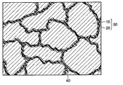
図3は、図1中の2点鎖線IIIに囲まれた範囲を拡大して示す模式図である。図1および図3を参照して、α/β≧2.5の関係を満たす鉄粒子10は、ゆがんだ輪郭を有するいびつな形状に形成されている。さらに、鉄粒子10の表面には、細かい凹凸形状が存在し、大きい表面粗さで形成されている。
FIG. 3 is an enlarged schematic view showing a range surrounded by a two-dot chain line III in FIG. Referring to FIGS. 1 and 3,
図4は、図1中に示す軟磁性材料を用いて作製された圧粉磁心の表面を示す模式図である。図4を参照して、圧粉磁心は、鉄粒子10と、鉄粒子10の表面を取り囲む絶縁被膜20とから構成された複数の複合磁性粒子30を備える。複数の複合磁性粒子30の間には、有機物40が介在している。複数の複合磁性粒子30の各々は、複合磁性粒子30が有する凹凸の噛み合わせによって接合されていたり、有機物40によって接合されている。
FIG. 4 is a schematic view showing the surface of a dust core produced using the soft magnetic material shown in FIG. Referring to FIG. 4, the dust core includes a plurality of composite
鉄粒子10が有する輪郭がいびつで表面粗さの大きい形状は、絶縁被膜20の表面の転写されるため、複合磁性粒子30も鉄粒子10と同様に、輪郭がいびつで表面粗さの大きい形状に形成される。このため、複数の複合磁性粒子30の各々は、複雑に絡み合い、互いに噛み合った状態で接合されており、圧粉磁心の強度の向上が図られている。
Since the shape of the
続いて、この発明の実施の形態における軟磁性材料を用いて、図4中に示す圧粉磁心を製造する方法について説明を行なう。 Next, a method for manufacturing the dust core shown in FIG. 4 using the soft magnetic material in the embodiment of the present invention will be described.
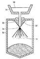
図5は、図1中に示す軟磁性材料を製造するためのアトマイズ装置を示す断面図である。図5を参照して、まず、鉄粒子の原料となる鉄塊を真空誘導炉51内に投入し、その真空誘導炉51に高周波電源を導入する。これにより、真空誘導炉51内の鉄塊を溶解して溶湯56とする。噴射ノズル54に向けて高圧水57を吹き付けるとともに、溶湯56を溶湯導入管53に供給する。高圧水57が吹き付けられることによって、溶湯56は噴霧され、その後、噴霧塔52内で急冷されることによって、複数の鉄粒子10からなる鉄粉末が形成される。
FIG. 5 is a sectional view showing an atomizing apparatus for producing the soft magnetic material shown in FIG. Referring to FIG. 5, first, an iron ingot as a raw material for iron particles is put into a
この際、噴霧塔52内での冷却速度を遅めに設定したり、鉄粒子10中に含まれる硬度を向上させる原因となる元素(特に、窒素、炭素、リンおよびマンガン)の割合を低減させることによって、ビッカース硬さHVが800未満の鉄粒子10を得ることができる。また、上述のアトマイズ工程の後に、水素中または不活性ガス雰囲気中で、500℃以上の温度条件の熱処理を鉄粉末に実施しても良い。この場合、鉄粒子10の内部に存在する歪みや応力を開放し、鉄粒子10の硬度を低減させることができる。
At this time, the cooling rate in the
また、上述のアトマイズ工程時に、水噴出圧力や水温等の条件を適当に設定することによって、鉄粒子10を輪郭がいびつで表面粗さの大きい形状に形成することができる。また、鉄粒子10の粒径を大きくするほど、鉄粒子10の表面に形成される凹凸形状を大きくすることができる。また、ガスアトマイズ法と比較して、水アトマイズ法の方が、鉄粒子10の表面に形成される凹凸形状を大きくすることができる。
Moreover, the
次に、得られた鉄粉末にリン酸処理を施すことによって、鉄粒子10の表面に絶縁被膜20を形成し、複合磁性粒子30を作製する。この絶縁被膜20は、鉄粒子10間の絶縁層として機能する。鉄粒子10を絶縁被膜20で覆うことによって、圧粉磁心の電気抵抗率ρを大きくすることができる。これにより、鉄粒子10間に渦電流が流れるのを抑制して、渦電流に起因する圧粉磁心の鉄損を低減させることができる。
Next, the obtained iron powder is subjected to a phosphoric acid treatment to form an insulating
なお、絶縁被膜20は、酸化物を含んでいても良い。この酸化物を含有する絶縁被膜20としては、リンと鉄とを含むリン酸鉄の他、リン酸マンガン、リン酸亜鉛、リン酸カルシウム、リン酸アルミニウム、酸化シリコン、酸化チタン、酸化アルミニウムまたは酸化ジルコニウムなどの酸化物絶縁体を使用することができる。絶縁被膜20は、図中に示すように1層に形成しても良いし、多層に形成しても良い。
Note that the insulating
また、絶縁被膜20の平均厚みは、5nm以上100nm以下とすることが好ましい。ここで言う平均厚みとは、組成分析(TEM−EDX:transmission electron microscope energy dispersive X-ray spectroscopy)によって得られる膜組成と、誘導結合プラズマ質量分析(ICP−MS:inductively coupled plasma-mass spectrometry)によって得られる元素量とを鑑みて相当厚さを導出し、さらに、TEM写真により直接、被膜を観察し、先に導出された相当厚さのオーダーが適正な値であることを確認して決定されるものをいう。
The average thickness of the insulating
次に、有機物40として、熱可塑性樹脂および非熱可塑性樹脂からなる強度発現用の第1の有機物と、高級脂肪酸系潤滑剤からなる潤滑用の第2の有機物とを準備する。第1の有機物としては、たとえば、熱可塑性ポリイミド、熱可塑性ポリアミド、熱可塑性ポリアミドイミド、ポリフェニレンサルファイド、ポリアミドイミド、ポリエーテルスルホン、ポリエーテルイミドまたはポリエーテルエーテルケトンなどの熱可塑性樹脂や、高分子量ポリエチレン、全芳香族ポリエステルまたは全芳香族ポリイミドなどの非熱可塑性樹脂を用いることができる。なお、高分子量ポリエチレンとは、分子量が10万以上のポリエチレンをいう。第2の有機物としては、ステアリン酸亜鉛、ステアリン酸リチウム、ステアリン酸カルシウム、ステアリン酸マグネシウム、パルミチン酸リチウム、パルミチン酸カルシウム、オレイン酸リチウムおよびオレイン酸カルシウムなどの高級脂肪酸系を用いることができる。
Next, as the
V型混合機を用いて、複合磁性粒子30と有機物40とを混合する。この際、後の工程で作製される成形体に対する上記の第1および第2の有機物の割合が、それぞれ0.001質量%以上0.2質量%以下となるように混合する割合を調整する。なお、有機物40として、第1および第2の有機物の両方を用いても良いし、いずれか一方を用いても良い。また、混合方法に特に制限はなく、たとえばメカニカルアロイング法、振動ボールミル、遊星ボールミル、メカノフュージョン、共沈法、化学気相蒸着法(CVD法)、物理気相蒸着法(PVD法)、めっき法、スパッタリング法、蒸着法またはゾル−ゲル法などのいずれを使用することも可能である。
The composite
次に、得られた混合粉末に対して加圧成形工程を実施する。図6から図8は、図4中に示す圧粉磁心を製造する際の加圧成形の工程を示す断面図である。図6を参照して、まず、金型装置71のバンドヒータ77に通電し、ダイ72の内壁73を40℃以上の温度まで加熱する。また、内壁73の加熱に変えて、先の工程で得られた混合粉末を加熱しても良いし、両方を加熱しても良い。さらに、これらを80℃以上200℃以下の温度まで加熱することが好ましい。
Next, a pressure forming process is performed on the obtained mixed powder. 6 to 8 are cross-sectional views showing the steps of pressure forming when the dust core shown in FIG. 4 is manufactured. Referring to FIG. 6, first, the
次に、内壁73に囲まれた空間74の上方に潤滑剤供給部78を位置決めする。エアーを用いて、潤滑剤供給部78の噴射ノズルから空間74に向けて金型潤滑剤91を吹き付ける。これにより、金型装置71の内壁73および底面76に金型潤滑剤91を付着させる。図中には、粉末状の金型潤滑剤91を模式的に示したが、液体状の金型潤滑剤91であっても良く、付着させる方法は、湿式および乾式のいずれであっても良い。金型潤滑剤91としては、たとえば、金属石鹸、ポリエチレン、アミド系ワックス、ポリアミド、ポリプロピレン、アクリル酸エステル重合体、メタクリル酸エステル重合体、フッ素系樹脂および層状潤滑剤などを用いることができる。また、これらの材料から2以上の材料を適当に選択し、混合したものを用いても良い。
Next, the
図7を参照して、空間74の上方にシュー79を位置決めし、シュー79から空間74に向けて、先の工程で得られた混合粉末15を供給する。図8を参照して、空間74の上方に上パンチ80を位置決めする。上パンチ80を下方に移動させ、たとえば、700MPaから1500MPaまでの圧力で混合粉末15を加圧成形する。この際、加圧成形する雰囲気は、不活性ガス雰囲気または減圧雰囲気とすることが好ましい。この場合、大気中の酸素によって混合粉末が酸化されるのを抑制できる。
Referring to FIG. 7,
この加圧成形の際、有機物40は、主にその中に含まれる第2の有機物の働きにより、隣り合う複合磁性粒子30間の潤滑剤として機能する。これにより、加圧成形時に鉄粒子10に歪みが導入されたり、絶縁被膜20同士が強く擦れ合って破壊されることを抑制する。
At the time of this pressure molding, the
その後、加圧成形により得られた成形体16を空間74から抜き出す。次に成形体16を、有機物40のガラス転移温度を超え、有機物40の熱分解温度以下の温度で熱処理する。これにより、有機物40が熱分解されるのを抑制しつつ、有機物40を複合磁性粒子30間に入り込ませることができる。これにより、主に有機物40に含まれる第1の有機物の働きによって、複合磁性粒子30同士が強固に接合され、成形体16の強度を向上させることができる。また別に、熱処理の実施により、加圧成形時に成形体16の内部に発生した歪みや転位を取り除くことができる。
Thereafter, the molded
最後に、成形体16に押出し加工や切削加工など適当な加工を施すことによって、図1中に示す圧粉磁心が完成する。
Finally, the dust core shown in FIG. 1 is completed by subjecting the molded
このように構成された軟磁性材料および圧粉磁心の製造方法によれば、鉄粒子10としてビッカース硬さHVが800未満の硬度の小さいものを使用しているため、加圧成形時に鉄粒子10が容易に塑性変形する。このため、複合磁性粒子30同士が、複雑に絡み合った状態に接合され、互いの結合力が大きくなる。これにより、加圧成形によって作製される成形体16の強度を向上させることができ、たとえば成形体16に切削加工を実施した場合にも欠損等を生じさせることなく加工を行なうことができる。
According to the manufacturing method of the soft magnetic material and the powder magnetic core configured as described above, since the
なお、このように作製した圧粉磁心を、たとえば、チョークコイル、スイッチング電源素子および磁気ヘッドなどの電子部品、各種モーター部品、自動車用ソレノイド、各種磁気センサならびに各種電磁弁などの製品として利用することができる。また、本実施の形態では、圧粉磁心を作製したが、このような磁性部品に限定されず、機械部品などを含んだ一般的な圧粉成形体を作製することが可能である。 The dust core produced in this way can be used as products such as electronic components such as choke coils, switching power supply elements and magnetic heads, various motor components, automotive solenoids, various magnetic sensors and various electromagnetic valves. Can do. In the present embodiment, the dust core is manufactured. However, the present invention is not limited to such a magnetic component, and it is possible to manufacture a general dust compact including a mechanical component.
以下に説明する実施例によって、本発明による軟磁性材料および圧粉成形体の製造方法の評価を行なった。 The production method of the soft magnetic material and the green compact according to the present invention was evaluated by the examples described below.
(実施例1)
ビッカース硬さHVを測定した複数種の鉄粉末を準備し、さらに、実施の形態に記載の方法に従って、それぞれの鉄粉末を構成する鉄粒子10の比表面積αおよび見かけの比表面積βを測定した。この際、ビッカース硬さの測定には、マイクロビッカース硬度計を用い、試験荷重を0.5Nとした。また、ガス吸着法による比表面積αの測定には、クリプトンガスを用いた。
Example 1
A plurality of types of iron powders whose Vickers hardness HV was measured were prepared, and the specific surface area α and the apparent specific surface area β of the
次に、リン酸鉄溶液を用いて、一部の鉄粉末にボンデ処理と呼ばれる湿式被覆法を実施し、鉄粒子10の表面に絶縁被膜20としてのリン酸鉄被膜を形成した複合磁性粒子30を作製した。この際、溶液の濃度を変化させることによって、絶縁被膜20の厚みを調整した。
Next, a composite
次に、得られた複合磁性粒子30および絶縁被膜20を設けなかった鉄粉末を、それぞれ圧力1275MPa(=13ton/cm2)の圧力で加圧成形し、サンプルAからVの成形体を形成した。この際、成形体の密度を7.5g/cm3に設定した。また、成形体の形状は、JIS規格の抗折試験に準じた20mmスパンのJIS試験片と同一のものとした。以上の工程により得られた成形体に対して、JIS規格に準じた抗折試験を実施し、抗折強度を測定した。測定された抗折強度の値を、各サンプルの成形体を構成する鉄粒子10および絶縁被膜20のデータとともに表1に示す。
Next, the obtained composite

表1を参照して分かるように、絶縁被膜20の有無にかかわらず、鉄粒子10のビッカース硬さHVを800未満としたサンプルにおいて、高い抗折強度を得ることができた。また、ビッカース硬さHVの値が同じであっても、さらにα/βの値を2.5以上としたサンプルでは、より高い抗折強度を得ることができた。
As can be seen with reference to Table 1, regardless of the presence or absence of the insulating
(実施例2)
実施例1のサンプルFの成形体に用いた鉄粉末に、複数種の絶縁被膜20をその厚みを変化させながら形成し、複合磁性粒子30を作製した。次に、実施例1と同様の方法により、その複合磁性粒子30からサンプル1から20のJIS試験片状の成形体を作製した。また別に、同じ複合磁性粒子30を用いて、サンプル1から20のリング状の成形体も作製した。
(Example 2)
A plurality of types of insulating
JIS試験片状の成形体に対しては、実施例1と同様に抗折試験を実施し、それぞれの成形体の抗折強度を求めた。また、リング状の成形体に対しては、最大値1T(テスラ)となる磁場を印加し、そのときの渦電流損係数を測定した。測定により得られた抗折強度および渦電流損係数の値を、各サンプルの成形体を構成する鉄粒子10および絶縁被膜20のデータとともに表2に示す。なお、表中に示す絶縁被膜第1層、第2層および第3層は、それぞれ絶縁被膜20が1層構造、2層構造および3層構造で形成されたことを意味している。
For the JIS test piece shaped molded body, the bending test was carried out in the same manner as in Example 1 to determine the bending strength of each molded body. Further, a magnetic field having a maximum value of 1 T (Tesla) was applied to the ring-shaped molded body, and the eddy current loss coefficient at that time was measured. The values of the bending strength and eddy current loss coefficient obtained by the measurement are shown in Table 2 together with the data of the
表2を参照して、絶縁被膜20の厚みが5nmより小さい場合、絶縁被膜20を設けることによる渦電流損係数の低減の効果を十分に得ることができなかった。また、絶縁被膜20の厚みが100nmを超える場合、渦電流損係数は低減したものの、抗折強度が若干低下した。これは、絶縁被膜20の厚みが大きすぎて鉄粒子10の有する凹凸形状が絶縁被膜20の表面に転写されず、複合磁性粒子30同士が十分に噛み合わなかったためと考えられる。これに対して、厚みが5nm以上100nm以下の絶縁被膜20を設けたサンプルでは、優れた強度と小さい渦電流損係数との両立を図ることができた。
Referring to Table 2, when the thickness of the insulating
(実施例3)
実施例1のサンプルQの成形体に用いた複合磁性粒子30に、複数種の有機物をその添加量を変化させながら混合した。実施例1と同様の方法により、得られた混合粉末からサンプル1から26のJIS試験片状の成形体とリング状の成形体とを作製した。その後、得られた成形体に対して、添加した有機物のガラス転位温度以上の温度条件の熱処理を実施した。
(Example 3)
A plurality of types of organic substances were mixed with the composite
実施例2と同様に、JIS試験片状の成形体から抗折強度を測定し、リング状の成形体から渦電流損係数を測定した。測定により得られた抗折強度および渦電流損係数の値を、各サンプルの成形体に添加した有機物のデータとともに表3に示す。なお、表中に示す添加樹脂は、実施の形態に記載の強度発現用の第1の有機物に相当し、表中に示す潤滑剤は、実施の形態に記載の潤滑用の第2の有機物に相当する。 In the same manner as in Example 2, the bending strength was measured from the JIS test piece-shaped molded body, and the eddy current loss coefficient was measured from the ring-shaped molded body. The values of the bending strength and eddy current loss coefficient obtained by the measurement are shown in Table 3 together with the data of organic substances added to the molded body of each sample. The additive resin shown in the table corresponds to the first organic material for strength development described in the embodiment, and the lubricant shown in the table corresponds to the second organic material for lubrication described in the embodiment. Equivalent to.
表3を参照して分かるように、適当な量の添加樹脂を混合することによって、抗折強度が向上し、適当な量の潤滑剤を混合することによって、渦電流損係数が低下した。このことから、添加樹脂および潤滑剤を適宜組み合わせて混合することによって、高強度と優れた磁気的特性との両方を達成できることを確認できた。 As can be seen with reference to Table 3, the bending strength was improved by mixing an appropriate amount of additive resin, and the eddy current loss coefficient was decreased by mixing an appropriate amount of lubricant. From this, it was confirmed that both high strength and excellent magnetic properties can be achieved by mixing the additive resin and the lubricant appropriately in combination.
なお、加圧成形時において、金型の内壁に潤滑剤を塗布することにより、成形体の強度をさらに10%以下の範囲で向上させることが可能である。また、金型の内壁や金型に供給する粉末を80℃以上200℃以下の温度にまで加熱すると、同様に成形体の強度をさらに10%以下の範囲で向上させることが可能である。また、これら双方を組み合わせて実施することにより、成形体の強度をさらに向上させることができる。 In addition, at the time of pressure molding, it is possible to further improve the strength of the molded body within a range of 10% or less by applying a lubricant to the inner wall of the mold. In addition, when the powder supplied to the inner wall of the mold or the mold is heated to a temperature of 80 ° C. or higher and 200 ° C. or lower, the strength of the molded body can be further improved within a range of 10% or less. Moreover, the intensity | strength of a molded object can further be improved by implementing combining these both.
今回開示された実施の形態および実施例はすべての点で例示であって制限的なものではないと考えられるべきである。本発明の範囲は上記した説明ではなくて特許請求の範囲によって示され、特許請求の範囲と均等の意味および範囲内でのすべての変更が含まれることが意図される。 It should be understood that the embodiments and examples disclosed herein are illustrative and non-restrictive in every respect. The scope of the present invention is defined by the terms of the claims, rather than the description above, and is intended to include any modifications within the scope and meaning equivalent to the terms of the claims.
10 鉄粒子、16 成形体、20 絶縁被膜、30 複合磁性粒子、40 有機物、71 金型装置、73 内壁、91 金型潤滑剤。
DESCRIPTION OF
Claims (6)
前記鉄粉末は、ビッカース硬さHVが800未満である複数の鉄粒子の集合体であり、ガス吸着法(BET法)によって測定された前記鉄粒子の比表面積をαとし、レーザー散乱回折法によって測定された平均粒径から算出した前記鉄粒子の見かけの比表面積をβとする場合、前記鉄粒子は、α/β≧2.5の関係を満たし、
前記複数の鉄粒子を金型に投入する工程と、
前記複数の鉄粒子を加圧成形して成形体を形成する工程とを備え、
前記複数の鉄粒子を金型に投入する工程は、熱可塑性樹脂および非熱可塑性樹脂の少なくともいずれか一方からなる第1の有機物を、前記成形体に対する前記第1の有機物の割合が0.001質量%以上0.01質量%以下となるように前記複数の鉄粒子に添加する工程を含む、圧粉成形体の製造方法。 A method for producing a green compact using iron powder,
The iron powder is an aggregate of a plurality of iron particles having a Vickers hardness HV of less than 800. The specific surface area of the iron particles measured by the gas adsorption method (BET method) is α, and the laser powder diffraction method is used. When the apparent specific surface area of the iron particles calculated from the measured average particle diameter is β, the iron particles satisfy the relationship of α / β ≧ 2.5,
Introducing the plurality of iron particles into a mold;
A step of pressure forming the plurality of iron particles to form a molded body,
The step of introducing the plurality of iron particles into the mold includes a first organic material composed of at least one of a thermoplastic resin and a non-thermoplastic resin, and a ratio of the first organic material to the molded body is 0.001. The manufacturing method of a compacting body including the process added to these iron particles so that it may become mass% or more and 0.01 mass% or less.
ずれか1項に記載の圧粉成形体の製造方法。 The step of putting the plurality of iron particles into the mold includes a step of heating at least one of the inner wall of the mold and the plurality of iron particles to a temperature of 40 ° C or higher. The manufacturing method of the compacting body of Claim 1.
Priority Applications (1)
| Application Number | Priority Date | Filing Date | Title |
|---|---|---|---|
| JP2004062141A JP4305222B2 (en) | 2004-03-05 | 2004-03-05 | Method for producing a green compact |
Applications Claiming Priority (1)
| Application Number | Priority Date | Filing Date | Title |
|---|---|---|---|
| JP2004062141A JP4305222B2 (en) | 2004-03-05 | 2004-03-05 | Method for producing a green compact |
Publications (3)
| Publication Number | Publication Date |
|---|---|
| JP2005248274A JP2005248274A (en) | 2005-09-15 |
| JP2005248274A5 JP2005248274A5 (en) | 2005-10-27 |
| JP4305222B2 true JP4305222B2 (en) | 2009-07-29 |
Family
ID=35029033
Family Applications (1)
| Application Number | Title | Priority Date | Filing Date |
|---|---|---|---|
| JP2004062141A Expired - Fee Related JP4305222B2 (en) | 2004-03-05 | 2004-03-05 | Method for producing a green compact |
Country Status (1)
| Country | Link |
|---|---|
| JP (1) | JP4305222B2 (en) |
Families Citing this family (8)
| Publication number | Priority date | Publication date | Assignee | Title |
|---|---|---|---|---|
| JP4654881B2 (en) * | 2005-11-02 | 2011-03-23 | 住友電気工業株式会社 | Dust core manufactured using soft magnetic material |
| JP4716434B2 (en) * | 2006-10-25 | 2011-07-06 | 住友電気工業株式会社 | Powder for compacting and method for producing powder for compacting |
| JP2009032860A (en) * | 2007-07-26 | 2009-02-12 | Kobe Steel Ltd | Dust core and iron-base powder for the same |
| KR100968688B1 (en) * | 2008-02-25 | 2010-07-06 | 김정태 | The driving chip the surface processing equipment |
| CN102792402B (en) * | 2011-03-09 | 2014-06-18 | 住友电气工业株式会社 | Green compact, manufacturing method for same, and reactor core |
| US9154883B2 (en) | 2011-09-06 | 2015-10-06 | Apple Inc. | Low rise speaker assembly having a dual voice coil driver |
| JP5929819B2 (en) * | 2013-04-19 | 2016-06-08 | Jfeスチール株式会社 | Iron powder for dust core |
| JP7377076B2 (en) * | 2019-11-19 | 2023-11-09 | 株式会社タムラ製作所 | Manufacturing method of powder magnetic core |
-
2004
- 2004-03-05 JP JP2004062141A patent/JP4305222B2/en not_active Expired - Fee Related
Also Published As
| Publication number | Publication date |
|---|---|
| JP2005248274A (en) | 2005-09-15 |
Similar Documents
| Publication | Publication Date | Title |
|---|---|---|
| US7641745B2 (en) | Soft magnetic material and method of producing powder compact | |
| US11011305B2 (en) | Powder magnetic core, and coil component | |
| JP4325950B2 (en) | Soft magnetic material and dust core | |
| JP4904159B2 (en) | Method for producing green compact and green compact | |
| JP5363081B2 (en) | Metallurgical powder, dust core, metallurgical powder manufacturing method and dust core manufacturing method | |
| JP5470683B2 (en) | Metal powder for dust core and method for producing dust core | |
| JP2007092162A (en) | Highly compressive iron powder, iron powder for dust core using the same and dust core | |
| JP2005286145A (en) | Method for manufacturing soft magnetic material, soft magnetic powder and dust core | |
| JP4305222B2 (en) | Method for producing a green compact | |
| JP2011243830A (en) | Powder magnetic core and method for manufacturing the same | |
| WO2017047761A1 (en) | Dust core | |
| JP6523778B2 (en) | Dust core and manufacturing method of dust core | |
| JP4627023B2 (en) | Soft magnetic material, dust core, and method for manufacturing dust core | |
| JP4507663B2 (en) | Method for producing soft magnetic material, soft magnetic powder and dust core | |
| WO2017082027A1 (en) | Pressed powder formed body, electromagnetic component, and pressed powder formed body production method | |
| JP2007048902A (en) | Powder magnetic core and its manufacturing method | |
| JP2009228108A (en) | Powder for metallurgy, and method for manufacturing powder for metallurgy | |
| JP2009235517A (en) | Metal powder for dust core and method for producing dust core | |
| JP2005248273A (en) | Soft magnetic material and method for producing powder magnetic core | |
| JP2017011073A (en) | Powder-compact magnetic core and method of manufacturing power-compact magnetic core | |
| JP2007116093A (en) | Soft magnetic material, method of manufacturing same, and method of manufacturing dust core | |
| WO2015045561A1 (en) | Dust core, method for producing dust core and coil component | |
| JP2007211341A (en) | Soft magnetic material, powder magnetic core, method for producing soft magnetic material and method for producing powder magnetic core | |
| JP2007211340A (en) | Soft magnetic material, powder magnetic core, method for producing soft magnetic material, and method for producing powder magnetic core | |
| CN112437965B (en) | Method for manufacturing dust core |
Legal Events
| Date | Code | Title | Description |
|---|---|---|---|
| A521 | Request for written amendment filed |
Free format text: JAPANESE INTERMEDIATE CODE: A523 Effective date: 20050824 |
|
| A621 | Written request for application examination |
Free format text: JAPANESE INTERMEDIATE CODE: A621 Effective date: 20061024 |
|
| A977 | Report on retrieval |
Free format text: JAPANESE INTERMEDIATE CODE: A971007 Effective date: 20080616 |
|
| A131 | Notification of reasons for refusal |
Free format text: JAPANESE INTERMEDIATE CODE: A131 Effective date: 20080624 |
|
| A521 | Request for written amendment filed |
Free format text: JAPANESE INTERMEDIATE CODE: A523 Effective date: 20080806 |
|
| A131 | Notification of reasons for refusal |
Free format text: JAPANESE INTERMEDIATE CODE: A131 Effective date: 20090113 |
|
| A521 | Request for written amendment filed |
Free format text: JAPANESE INTERMEDIATE CODE: A523 Effective date: 20090311 |
|
| TRDD | Decision of grant or rejection written | ||
| A01 | Written decision to grant a patent or to grant a registration (utility model) |
Free format text: JAPANESE INTERMEDIATE CODE: A01 Effective date: 20090407 |
|
| A01 | Written decision to grant a patent or to grant a registration (utility model) |
Free format text: JAPANESE INTERMEDIATE CODE: A01 |
|
| A61 | First payment of annual fees (during grant procedure) |
Free format text: JAPANESE INTERMEDIATE CODE: A61 Effective date: 20090420 |
|
| R150 | Certificate of patent or registration of utility model |
Free format text: JAPANESE INTERMEDIATE CODE: R150 |
|
| FPAY | Renewal fee payment (event date is renewal date of database) |
Free format text: PAYMENT UNTIL: 20120515 Year of fee payment: 3 |
|
| FPAY | Renewal fee payment (event date is renewal date of database) |
Free format text: PAYMENT UNTIL: 20130515 Year of fee payment: 4 |
|
| LAPS | Cancellation because of no payment of annual fees |