【0001】
【発明の属する技術分野】
本発明は遊技機に関し、特に、ボックスベース及びボックスカバーのこじ開けを防止して、回路基板への不正行為を防ぐことができる遊技機用基板ボックスを備えた遊技機に関するものである。
【0002】
【従来の技術】
近年、パチンコ機などの遊技機は、その遊技盤に設けられる入賞装置および表示装置等を制御して、遊技の興趣を盛り上げるものが主流となっている。この入賞装置および表示装置の制御は、IC,LSI等の多数の電子部品を搭載したロジック回路基板、又は、マイクロコンピュータを有する回路基板により行われる。これらの回路基板はボックスベースおよびボックスカバーを備えた基板ボックスに被包されており、この基板ボックスのボックスベース及びボックスカバーの一部分は、特殊な封印ねじにより接合され封印されている。
【0003】
この封印に用いられる封印ねじは、その頭部にねじ回し工具の先端がねじ込み方向にのみ係合される十字溝が形成されている。よって、この十字溝にねじ回し工具が係合され反ねじ込み方向へ回転されると、ねじ回し工具が空回りされて封印ねじの抜き取りが防止されるのである。従って、かかる封印ねじで基板ボックスを封印することによって、基板ボックスの開封が防止されるので、基板ボックスに被包された回路基板への接触行為や、その回路基板からROMを取り外して交換し遊技内容を変更する不正行為が防止される。
【0004】
【発明が解決しようとする課題】
しかしながら、上記の基板ボックスでは、封印ねじによってボックスベース及びボックスカバーの一部分のみが接合されるとともに、ボックスベース及びボックスカバーの合わせ目(当接面)が略平面状にそれぞれ形成されている。このため、ボックスベース及びボックスカバーの合わせ目に薄板状の工具等を差し込むことにより、ボックスベース及びボックスカバーの合わせ目に隙間が開けられ、基板ボックスがこじ開けられてしまうという問題点があった。
【0005】
このように基板ボックスがこじ開けられると、ボックスベース及びボックスカバーの合わせ目に生じる隙間から薄板状の工具等を差し込むことができるので、その薄板状の工具や針金等の先端部分で回路基板の回路パターンなどの信号線が削られ切断されて、遊技内容が不正に変更されてしまうという問題点があった。
【0006】
本発明は上述した問題点を解決するためになされたものであり、ボックスベース及びボックスカバーのこじ開けを防止して、回路基板への不正行為を防ぐことができる遊技機用基板ボックスを備えた遊技機を提供することを目的としている。
【0007】
【課題を解決するための手段】
この目的を達成するため、請求項1記載の遊技機は、遊技機の制御部品と該制御部品に電気的に接続されるコネクタとを搭載した回路基板と、ボックスベースと、そのボックスベースと合体し該ボックスベースとともに前記回路基板を収容するボックスカバーとを有する四角形状の遊技機用基板ボックスを備えており、前記回路基板は、前記制御部品を配設した制御部品搭載位置と、前記回路基板の側縁部にコネクタを配設したコネクタ搭載位置と、位置決め穴とを基板上に備えて四角形状に形成され、前記ボックスカバーは、前記回路基板を収容した前記遊技機用基板ボックスにおいて前記制御部品搭載位置と対向する四角形状の天板部と、該天板部から前記ボックスベース側に延設される側壁と、前記天板部の一辺から前記ボックスベース側に延設される仕切り手段と、前記回路基板の前記位置決め穴にはめ合わされる位置決め突起が設けられる位置決め手段と、前記ボックスカバーから側方に延設され係合面を有する第1係合手段と、封印ネジを挿入可能な第1封印手段とを備え、前記仕切り手段は、前記回路基板を収容した前記遊技機用基板ボックスにおいて前記制御部品搭載位置と前記コネクタ搭載位置とを区別するように前記天板部から前記回路基板側に向けて立設され前記ボックスカバーと一体成形された仕切り側壁部と、該仕切り壁部に連設され、前記コネクタ搭載位置の基板面を覆うと共に前記コネクタに対応したコネクタ開口が設けられた覆設部とを備え、前記ボックスベースは、該ボックスベースから側方に延設され前記第1係合手段の前記係合面に対応する係止面を有する第2係合手段と、前記第1封印手段に対応し前記封印ネジを挿入可能な第2封印手段とを備えるものであり、前記遊技機用基板ボックスは、前記第1封印手段および第2封印手段に挿入されて該第1封印手段と第2封印手段とを連結する封印ネジを有し、前記回路基板の前記位置決め穴に前記位置決め手段の前記位置決め突起をはめ合わせた場合に前記コネクタ搭載位置に配設される前記コネクタが前記コネクタ開口から露出され、前記回路基板を前記ボックスカバーに係止し、前記回路基板を係止した前記ボックスカバーと前記ボックスベースとを対向させてから相対的に所定量スライド移動させることで、前記第2係合手段の前記係止面が前記ボックスカバーの前記天板部方向への前記第1係合手段の前記係合面の移動を抑制するように前記第1係合手段と前記第2係合手段とが係合し、該係合状態の前記遊技機用基板ボックスの前記第1封印手段と前記第2封印手段とに前記スライド移動方向とは交差する方向から前記封印ネジを挿入して封止するものであり、前記側壁のうち前記仕切り手段が設けられる一辺と対向する辺から前記ボックスベース側に延設される側壁は、前記ボックスカバーと前記ボックスベースとが前記封印ネジによって封止された状態では、前記回路基板の前記コネクタ搭載位置と反対側の前記回路基板面より前記ボックスベース側に延出されている。
【0008】
請求項2記載の遊技機は、請求項1記載の遊技機において、前記遊技機は、パチンコ機である。
【0009】
【発明の実施の形態】
以下、本発明の好ましい実施例について、添付図面を参照して説明する。図1は、本発明の遊技機用基板ボックスの一実施例である主制御基板ボックス(以下、単に、基板ボックスと称す。)1が配設されたパチンコ機Pの裏面図である。図1に示すように、基板ボックス1は、薄板鋼材等で構成された薄皿状の取付部材P1により、遊技機の一種であるパチンコ機Pの遊技盤P2の裏面に設けられた入賞球集合カバーP3に取り付けられている。
【0010】
基板ボックス1は、パチンコ機Pの遊技内容に関する制御プログラムやデータを記憶したROM等の電子部品(制御部品)が搭載された主制御基板7(図2参照)を被包するためのものであり、主に、ボックスベース2と、そのボックスベース2に覆設されるボックスカバー3とを備えている。
【0011】
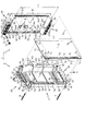
図2は、基板ボックス1の分解斜視図であり、図2中の矢印Aは、ボックスカバー3をボックスベース2に結合するために、ボックスカバー3をボックスベース2に対して相対的にスライドさせる方向を示している。尚、図2では、スペーサ2a4及びスペーサ2a5の図示を省略している。
【0012】
図2に示すように、基板ボックス1のボックスベース2及びボックスカバー3はいずれも略矩形椀状体に形成されており、ボックスベース2は後述する主制御基板7を収容(設置)可能に形成されている。この基板ボックス1によれば、ボックスベース2内に後述する主制御基板7を収容(設置)した状態で、ボックスベース2及びボックスカバー3における互いの開口面(開放部分)を対向させ合致(合体)させることにより、ボックスカバー3がボックスベース2に覆設され、主制御基板7を被包することができる。尚、図2では、ボックスカバー3を裏面(後面)側から斜視しており、主制御基板7の部品面71(図2の裏側面)に搭載される電子部品を省略して図示している。
【0013】
ボックスベース2は、後述する主制御基板7が設置される略矩形平板状の底板2aと、その底板2aの4つの端辺にそれぞれ(図2の紙面に対する手前側へ)立設される略平板状の側壁板2b,2c,2e,2fとを備えている。これらの側壁板2b,2c,2e,2fの各端部は平面視ロ字状となるように連設されており、ボックスベース2は、これら5枚の底板2a、側壁板2b,2c,2e,2fにより1面に開放部分が設けられた略矩形椀状体に形成されている。また、側壁板2b,2cの外面には、基板ボックス1を封印するボックス封印具10の封印ユニット20がそれぞれ配設されている。尚、ボックス封印具10の封印ユニット20についての説明は後述する。
【0014】
ボックスベース2の内部には、主制御基板7を収容するための略凹状の空間である収容空間2dが設けられている。この収容空間2dは、その長手方向(図2の上下方向)幅、即ち、側壁板2b,2cの対向面間幅が幅長L1に形成されており、主制御基板7の長手方向(図2の上下方向)における幅長L2より大きく形成されている(L1>L2)。しかも、収容空間2dにおける幅長L1の方向、及び、主制御基板7における幅長L2の方向は、ボックスカバー3のスライド方向(図2の矢印A方向)と一致している。
【0015】
側壁板2eは、ボックスカバー3の側壁板3dに対応して立設されており、ボックスカバー3がボックスベース2に覆設された場合に、側壁板3dとともに基板ボックス1の左側面(図2及び図4の左側)を塞ぐものである。この側壁板2eには、略同一形状の矩形枠状体に形成された4つの係止枠2e1が設けられている。各係止枠2e1は、後述するボックスカバー3の4つの係止爪3d1を回動可能かつ摺動可能に係止するものであり、この係止によってボックスベース2の側壁板2eとボックスカバー3の側壁板3dとを連結し、ボックスカバー3をボックスベース2に対して開閉可能に結合することができる。
【0016】
各係止枠2e1は、側壁板2eにおける底板2aの長手方向(図2の上下方向)に略等間隔で設けられており、この各係止枠2e1の間隔は間隔幅t1とされている。また、各係止枠2e1には、各係止爪3d1が挿入可能な係止溝2e2がそれぞれ穿設されている。これらの各係止溝2e2は、後述するボックスカバー3の4つの係止爪3d1をボックスベース2の長手方向へ向けて摺動可能に係止するために、ボックスベース2の長手方向、即ち、底板2aの長手方向幅が幅長w1の長溝状にそれぞれ形成されている。
【0017】
しかも、これらの各係止溝2e2の長手方向(図2の上下方向)両端側には、ボックスカバー3の各係止爪3d1の摺動位置を制限する制限壁2e3がそれぞれ設けられている。よって、これらの各制限壁2e3により、ボックスカバー3がボックスベース2に対して相対的にスライドする際に、ボックスカバー3の各係止爪3d1の摺動量が制限され、ボックスカバー3の相対的なスライドが規制されるのである。
【0018】
側壁板2fは、ボックスカバー3の仕切部材5に対応して立設されており、ボックスカバー3がボックスベース2に覆設された場合に、仕切部材5とともに基板ボックス1の右側面(図2及び図4の右側)を塞ぐものである。また、側壁板2fは、基板ボックス1に収納された主制御基板7に接続されるケーブル(配線部材)を導出するための導出口2f1を備えている。
【0019】
また、底板2aの前面における側壁板2c,2eの連設部分の隅(図2の左下側)には略円柱状のスペーサ2a1が突設され、底板2aの前面における側壁板2c側(図2の下側)の縁部略中央には略板状のスペーサ2a2が底板2a及び側壁板2cに跨って突設されている。更に、底板2a前面には、側壁板2f側の縁部(図2の右側)に底板2aの長手方向(図2の上下方向)へ向けて連続した略板状のスペーサ2a3が立設されている。
【0020】
ボックスベース2の側壁板2bには矩形板状のロック板2gが外方(図2の上方)へ向けて突設される一方、ボックスベース2の側壁板2cには後述するボックスカバー3のロック板3eが係止される矩形平板状の結合板2hが配設されている。この結合板2hには後述するロック板3eが挿入可能な結合口2iが穿設されており、ボックスベース2に合致されたボックスカバー3を矢印A方向へスライドさせると、かかる結合口2iへロック板3eを挿入することができる。
【0021】
その結果、ボックスカバー3のロック板3eはボックスベース2の結合板2hに係止され、ボックスベース2およびボックスカバー3が結合されるので、かかる結合状態で、ボックスカバー3が各係止枠2e1及び後述する各係止爪3d1を介して回動され開放されることを防止することができるのである。
【0022】
ボックスカバー3は、ボックスベース2の底板2aに対向してボックスベース2の開口面(図2の手前側)を覆う略平板状の天板3aと、その天板3aの長手方向(図2の上下方向)における両端に立設された側壁板3b,3cと、天板3aの一側縁部(図2右側)から外方へ傾斜した側壁板3dとを備えている。このボックスカバー3の側壁板3b,3cには、基板ボックス1を封印するため、上記した封印ユニット20に対向して封印ユニット30がそれぞれ配設されている。なお、ボックス封印具10の封印ユニット30についての説明は後述する。
【0023】
ボックスカバー3の側壁板3dは、天板3aの一側縁部(図2の右側)から傾斜しつつ延出されており、この側壁板3dにおける延出部分の端面(図2の手前側面)には上述した各係止枠2e1に対応して4つの係止爪3d1が略等間隔でそれぞれ設けられている。これらの各係止爪3d1の先端部分は略J字状にそれぞれ屈曲形成されており、かかる係止爪3d1の先端部分は係止枠2e1の係止溝2e2に挿入可能に形成されている。この係止爪3d1を係止溝2e2へ挿入することにより、各係止爪3d1が各係止枠2e1に係止されるのである。また、各係止爪3d1の長手方向幅は幅長w2に形成され、各係止溝2e2の幅長w1より幅狭に形成されている(w1>w2)。
【0024】
側壁板3dにおける延出部分の端面(図2の手前側面)であって、上述した各係止爪3d1の間部分には、複数枚(例えば、3枚)の略平板状の遮蔽板3d2が一体的に立設されている。この複数の遮蔽板3d2は、ボックスカバー3がボックスベース2に覆設された場合に、側壁板3dと側壁板2eとの対向面間(合わせ目)を遮蔽して塞ぐものである(図5(b)参照)。また、各遮蔽板3d2の長手方向(図2の上下方向)幅は幅長w3に形成され、この各遮蔽板3d2の幅長w3は各係止枠2eの間隔幅t1より幅狭に形成されている(w3<t1)。
【0025】
また、ボックスカバー3の側壁板3cには矩形板状のロック板3eが外方(図2の下方)へ向けて突設される一方、ボックスカバー3の側壁板3bには上述したボックスベース2のロック板2gが係止される矩形平板状の結合板3fが配設されている。この結合板3fには上述したロック板2gが挿入可能な結合口3gが穿設されており、ボックスベース2に合致されたボックスカバー3を矢印A方向へスライドさせると、かかる結合口3gへロック板2gを挿入することができる。その結果、ボックスベース2のロック板2gはボックスカバー3の結合板3fに係止され、ボックスベース2およびボックスカバー3が結合されるので、かかる結合状態で、ボックスカバー3が各係止枠2e1及び後述する各係止爪3d1を介して回動され開放されることを防止することができるのである。
【0026】
ボックスカバー3の側壁板3cの内側面には略L字板状の内壁板3hが隣接して形成されている。この内壁板3hは、天板3aから主制御基板7側(図2の手前側)へ向けて立設されており、その端部が側壁板3cの端部より突出して形成されている。このため、ボックスカバー3がボックスベース2に覆設された場合に、内壁板3hの端部はボックスベース2の側壁板2c前端より底板2a側へ突出するのである。
【0027】
よって、ボックスベース2に覆設されたボックスカバー3を矢印A方向へスライドした場合に、内壁板3h端部をボックスベース2の側壁板2c前端に引っ掛けることができる。このように、内壁板3hが側壁板2cに引っ掛かることにより、ボックスカバー3の矢印A方向へのスライドを停止させることができ、ボックスカバー3をボックスベース2に確実に合致させることができる。
【0028】
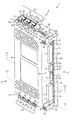
図3は、ボックスベース2に合致されたボックスカバー3がスライドされて結合される以前の状態における基板ボックス1の側断面図であり、図3中の矢印Aは、ボックスカバー3をボックスベース2に結合するために、ボックスカバー3をボックスベース2に対して相対的にスライドさせる方向を示している。尚、図3では、スペーサ2a3を省略して図示している。
【0029】
図3に示すように、底板2aの前面における側壁板2b,2eの連設部分の隅(図3の上側)には円柱状のスペーサ2a4が突設され、底板2aの前面における側壁板2b側縁部には略板状のスペーサ2a5が底板2a及び側壁板2bに跨って突設されている。尚、スペーサ2a4は、スペーサ2a1と上下対称に突設され、スペーサ2a5はスペーサ2a2と上下対称に突設されている。
【0030】
スペーサ2a1〜2a5は、ボックスベース2内に主制御基板7が収容される場合に、主制御基板7の半田面72側縁部(図2の手前側面)に当接して主制御基板7を支持するものであり、主制御基板7と底板2aとの間に隙間を設けて、その半田面72と底板2aとの接触を防止することができる。
【0031】
よって、収容空間2d内で主制御基板7をボックスカバー3と共にスライドさせる場合には、主制御基板7と底板2aとの間に隙間により、主制御基板7の半田面72から底板2aへ向けて突出する電子部品等の接続用ピン(図示せず)などが底板2aに引っ掛かることが防止されるので、主制御基板7を収容空間2d内で円滑にスライドさせることができる。しかも、これらのスペーサ2a1〜2a5は、底板2aからの突出高さが略等しくされており、主制御基板7を収容空間2d内にガタつかせずに収容することができる。
【0032】
ボックスカバー3とボックスベース2とが合致され、かつ、ボックスカバー3が矢印A方向へスライドされる以前の状態では、収容空間2dの側壁板2cとその側壁板2cと対向する主制御基板7端部(図2及び図3の下側端)との間に幅長L1と幅長L2の差分長さの空隙L3(=L1−L2)を設けることができる。よって、かかる空隙L3が設けられることにより、主制御基板7は、後述するように、ボックスカバー3の矢印A方向へ向けたスライドに伴って、収容空間2d内で矢印A方向へスライドされるのである。
【0033】
また、各係止爪3d1が係止された各係止溝2e2内には、係止爪3d1と係止溝2e2の長手方向における差分長さ分の空隙w4(=w1−w2)が設けられている。よって、各係止爪3d1が係止溝2e2に挿入された場合には、ボックスカバー3を、係止溝2e2および係止爪3d1の空隙w4分だけ矢印A方向へスライドさせることができるのである。即ち、空隙w4は、ボックスカバー3のボックスベース2に対する相対的なスライド量と一致するのである。
【0034】
しかも、ボックスカバー3のボックスベース2に対するスライド量と一致する係止溝2e2および係止爪3d1の空隙w4は、上述したボックスベース2の収容空間2dと主制御基板7との空隙L3より小さくされている(L3>w4)。よって、図3に示す状態からボックスカバー3と共に主制御基板7を矢印A方向への空隙w4の長さ分スライドさせる場合に、主制御基板7における側壁板2cとの対向端(図3の下側)がボックスベース2の側壁板2bと衝突して破損することを防止できる。
【0035】
また、各係止枠2e1の間部分には遮蔽板3d2がそれぞれ入り込んでおり、かかる状態で、各遮蔽板3d2の下端面(図3下側)とそれに対向する各係止枠2e1の上端面との間には空隙w5(=t1−w3)が設けられている。しかも、この空隙w5は、空隙w4より若干小さくされている(w5<w4)。よって、図3に示す状態からボックスカバー3と共に主制御基板7を矢印A方向への空隙w4の長さ分スライドさせる場合に、各遮蔽板3d2が各係止枠2e1と衝突して破損することを防止することができる。
【0036】
また、上述した側壁板3dにおけるボックスカバー3の長手方向両側近傍には、天板3a側端(図2左側)から係止爪3d1側端(図2右側)へ向けて略円柱状の位置決め部材4,4がそれぞれ立設されている。この一対の位置決め部材4,4は、後述する主制御基板7をボックスカバー3の所定位置に位置決めするためのものである。位置決め部材4,4は、ボックスカバー3に一体成形されており、ボックスカバー3と同様に、耐衝撃性を有するポリカーボネート樹脂等の合成樹脂等で構成されている。
【0037】
位置決め部材4,4は、その先端(図2の右側)に略円柱状の位置決め突起4a,4aがそれぞれ突設されている。これらの位置決め突起4a,4aは、その外形が後述する主制御基板7に穿設される位置決め穴7g,7gの開口形状に適合して形成されており、かかる位置決め穴7g,7gに嵌合可能に形成されている。よって、位置決め突起4a,4aが主制御基板7の位置決め穴7g,7gに嵌合することにより、主制御基板7をボックスカバー3に位置決めすることができる。しかも、かかる位置決め部材4,4が主制御基板7の各位置決め穴7g,7gに嵌合することにより、主制御基板7はボックスカバー3に引っ掛けられるので、ボックスカバー3がスライドされる場合に、ボックスカバー3と共に主制御基板7をボックスベース2の収容空間2d内で矢印A方向へ向けてスライドさせることができるのである。
【0038】
また、各位置決め部材4,4の各位置決め突起4a,4aは、その突出長さが主制御基板7の板厚より小さく形成されており、主制御基板7の位置決め穴7g,7g内に嵌合される場合に、主制御基板7の半田面72側から突出することが防止されている(図3参照)。よって、ボックスカバー3と共に主制御基板7をボックスベース2の収容空間2d内でスライドさせる場合に、位置決め部材4,4の各位置決め突起4a,4aがボックスベース2の底板2aなどに引っ掛かることが防止されるので、主制御基板7を収容空間2d内で円滑にスライドさせることができるのである。
【0039】
ボックスカバー3における側壁板3dの反対側縁部(図2の左側)には、その長手方向(図2の上下方向)のほぼ全域に、天板3aから主制御基板7側へ向けて仕切部材5が立設されている。この仕切部材5は、ボックスベース2と一体成形されており、ボックスベース2と同様に、耐衝撃性を有するポリカーボネート樹脂等の合成樹脂等で構成されている。
【0040】
仕切部材5は、ボックスカバー3の天板3aに対して略直角方向へ向けて連接されつつ立設される略板状の仕切り板5aと、その仕切り板5aにおける天板3aの反対側端部からボックスカバー3の外方(図2の左方)へ向けて略直角に延出される略平板状の覆設板5bとを備えている。仕切部材5は、基板ボックス1内に主制御基板7が収納された場合に、主制御基板7におけるコネクタ7b〜7f配置側縁部に配置されるように構成されており、その仕切り板5aにより基板ボックス1の内外部を仕切り、基板ボックス1の外部からの主制御基板7への接触行為を防止することができる。
【0041】
仕切り板5aは、その長手方向(図2の上下方向)両側に、ボックスカバー3をボックスベース2に固定するビス9,9が挿入可能な通穴5c,5cがそれぞれ穿設されている。各通穴5c,5cは、ボックスカバー3の天板3a外面(図2の裏側面)から仕切部材5の覆設板5b側端面(図2の手前側面)に貫通してそれぞれ穿設されるとともに、後述する主制御基板7の各通穴7a,7aにそれぞれ対応して穿設されている。よって、基板ボックス1内に主制御基板7が収納された場合には、図4に示すように、ビス9,9を各通穴5c,5cにそれぞれ挿入することにより、これらのビス9,9のねじ部先端は、主制御基板7の各通穴7a,7aを通過しボックスベース2の底板2aに到達するので、各ビス9,9をボックスベース2の底板2aにねじ込み、仕切部材5を介して、ボックスカバー3及び主制御基板7をボックスベース2にまとめてねじ止めすることができる。
【0042】
また、図2に示すように、仕切部材5の覆設板5aには、主制御基板7との当接面(図2手前側面)に正面視略矩形状に形成された5つのコネクタ口5d〜5hが穿設されている。この各コネクタ口5d〜5hは、その断面形状が後述する主制御基板7に配置された5つのコネクタ7b〜7fの外形に適合してそれぞれ形成されており、かかるコネクタ7b〜7fが挿嵌可能に形成されている。
【0043】
よって、図4に示すように、仕切部材5が主制御基板7の縁部(図4の右側)に配置される場合には、主制御基板7の各コネクタ7b〜7fを仕切部材5の各コネクタ口5d〜5hに挿嵌された各コネクタ7b〜7fを基板ボックス1の外部に露出させることができるのである。しかも、覆設板5bは、その各コネクタ口5d〜5hの断面形状が各コネクタ7b〜7fの外形に適合して形成されているので、各コネクタ口5d〜5hから主制御基板7における各コネクタ7b〜7f以外の部分を覆い隠して、主制御基板7への接触行為を防止できる。
【0044】
また、これらのコネクタ口5d〜5hは、その断面形状が主制御基板7の各コネクタ7b〜7fの外形に適合して形成されているので、これらの各コネクタ7b〜7fが挿嵌されることにより、主制御基板7を仕切部材5の所定位置に位置決めすることもできる。しかも、主制御基板7は、そのコネクタ7b〜7f及び覆設板5bのコネクタ口5d〜5hを介して、仕切部材5に引っ掛けられるので、ボックスカバー3がスライドされる場合に、ボックスカバー3及び仕切部材5と共に主制御基板7をボックスベース2の収容空間2d内で矢印A方向へ向けてスライドさせることができるのである。
【0045】
仕切部材5の長手方向(図2の上下方向)両側近傍には、天板3a側端(図2の左側)から覆設板5b側端(図2の右側)へ向けて略円柱状の位置決め部材6,6がそれぞれ立設されている。この一対の位置決め部材6,6は、後述する主制御基板7を仕切部材5の所定位置に位置決めするためのものである。位置決め部材6,6は、ボックスカバー3及び仕切部材5に一体成形されており、ボックスカバー3及び仕切部材5と同様に、耐衝撃性を有するポリカーボネート樹脂等の合成樹脂等で構成されている。
【0046】
位置決め部材6,6は、その先端(図2の右側)に略円柱状の位置決め突起6a,6aがそれぞれ突設されている。これらの位置決め突起6a,6aは、その外形が後述する主制御基板7に穿設される位置決め穴7h,7hの開口形状に適合して形成されており、かかる位置決め穴7h,7hに嵌合可能に形成されている。よって、位置決め突起6a,6aが主制御基板7の位置決め穴7h,7hに嵌合することにより、主制御基板7を仕切部材5の所定位置に位置決めすることができる。しかも、かかる位置決め部材6,6が主制御基板7の各位置決め穴7h,7hに嵌合することにより、主制御基板7はボックスカバー3及び仕切部材5に引っ掛けられるので、ボックスカバー3及び仕切部材5がスライドされる場合に、これらと共に主制御基板7をボックスベース2の収容空間2d内で矢印A方向へ向けてスライドさせることができるのである。
【0047】
このように、仕切部材5が一体成形されたボックスカバー3によれば、上述した位置決め部材4,4及び位置決め部材6,6により、主制御基板7の四隅が位置決めされるので、主制御基板7をガタつかせることなくボックスカバー3に仮止めすることができるのである。
【0048】
しかも、かかる位置決め部材4,4及び位置決め部材6,6は、その位置決め突起4a,4a及び位置決め突起6a,6aが主制御基板7の各位置決め穴7g,7g及び位置決め穴7h,7hにそれぞれ嵌合され、主制御基板7の四隅を位置決めするので、ボックスカバー3がボックスベース2に対して相対的にスライドされる場合に、収容空間2d内でスライドされる主制御基板7がそのスライド方向に対して傾きズレることを防止して、円滑にスライドさせることができる。
【0049】
また、各位置決め部材6,6の各位置決め突起6a,6aは、その突出長さが主制御基板7の板厚より小さく形成されており、主制御基板7の位置決め穴7h,7h内に嵌合される場合に、主制御基板7の半田面72側から突出することが防止されている。よって、ボックスカバー3と共に主制御基板7をボックスベース2の収容空間2d内でスライドさせる場合に、位置決め部材6,6の各位置決め突起6a,6aがボックスベース2の底板2aなどに引っ掛かることが防止されるので、主制御基板7を収容空間2d内で円滑にスライドさせることができるのである。
【0050】
主制御基板7は、ボックスカバー3の天板3aと対向する部品面71にパチンコ機Pの遊技内容に関する制御プログラムやデータを記憶したROM等の電子部品(図示せず)が搭載されるものであり、矩形薄板状に形成されている。この主制御基板7は、仕切部材5に対向する縁部(図2の左側)における長手方向(図2の上下方向)両端近傍に上述したビス9,9が挿入可能な2つの通穴7a,7aがそれぞれ穿設されている。また、主制御基板7の部品面71における仕切部材5との対向部分(図2の左側)には複数(5個)の雄型のコネクタ7b〜7fが配置されている。これらのコネクタ7b〜7fは、図4に示すように、仕切部材5が主制御基板7の右側縁部に配置される場合に、仕切部材5の各コネクタ口5d〜5hに挿嵌可能にそれぞれ形成されている。よって、かかる各コネクタ7b〜7fを仕切部材5の各コネクタ口5d〜5hに挿嵌することにより、各コネクタ7b〜7fを基板ボックス1の外部に露出させることができるのである。
【0051】
また、図2に示すように、主制御基板7の上部に配置されるコネクタ7bは、アース線(配線部材)の一端に配設される雌型のコネクタBが嵌合可能に形成されている。また、他のコネクタ7c〜7fには、フラットケーブル(配線部材)の一端に配設される雌型のコネクタC〜Fが嵌合可能に形成されている。尚、図2では、アース線およびフラットケーブルの図示を省略している。
【0052】
また、主制御基板7の一側縁部(図2右側)には、上述した位置決め部材4,4の各位置決め突起4a,4aに対応して、開口形状が略円形状の位置決め穴7g,7gがそれぞれ突設される一方、主制御基板7の他側縁部(図2左側)には、上述した位置決め部材6,6の各位置決め突起6a,6に対応して、開口形状が略円形状の位置決め穴7h,7hがそれぞれ突設されている。位置決め穴7g,7gは、その開口形状が上述した位置決め突起4a,4aの外形に適合して形成されており、かかる位置決め突起4a,4aを嵌合可能に形成されている。一方、位置決め穴7h,7hは、その開口形状が上述した位置決め突起6a,6aの外形に適合して形成されており、かかる位置決め突起6a,6aを嵌合可能に形成されている。
【0053】
また、ボックスベース2の底板2aの裏面には、パチンコ機Pに配設される取付部材P1(図1参照)に基板ボックス1を掛止するためのボックスロック板8が取着される。このボックスロック板8は透明なABS樹脂等の合成樹脂等で略台形薄板状に形成されており、ボックスベース2の底板2aの裏面(図2の奥側)にねじ止め等により取着されている。
【0054】
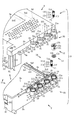
図4は、基板ボックス1の組立後の外観斜視図である。図4に示すように、ボックスカバー3の前面上下部分には上述したビス9,9が挿入可能な5c,5cがそれぞれ穿設されている。この各通穴5c,5cは、上述した主制御基板7の各通穴7a,7aに対応して穿設されており、ボックスベース2にボックスカバー3を覆設した場合に、ボックスカバー3の天板3a外面側(図4の手前側面)から各通穴5c,5cへそれぞれ挿入されたビス9,9を主制御基板7の各通穴7a,7aを通過させてボックスベース2の底板2aにねじ込み、ボックスカバー3、仕切部材5及び主制御基板7をボックスベース2にまとめて固定することができる。
【0055】
ボックスカバー3における各通穴5c,5cが穿設された部分には、封印シール10,10が貼付されている。この封印シール10,10は、特殊な粘着材が塗布されたシール材で構成されており、この封印シール10,10が貼付された後に剥がされると、シール材から粘着材が剥がれてしまう。よって、一度剥がされた封印シール10,10を再度貼付することができないので、封印シール10,10が不正に剥がされた場合には、かかる不正行為を容易に発見することができるのである。
【0056】
また、封印シール10,10は、ボックスベース2とボックスカバー3とに跨って貼付され、基板ボックス1の開封を防止するように貼付される。この場合、各封印シール10,10は各通穴5c,5cに覆い被さるように貼付されるので、各通穴5c,5cに挿入されたビス9,9の抜き取り行為を防止することができるのである。
【0057】
図5(a)は、図4のVa−Va線における係止枠2e1及び係止爪3d1の側断面図であり、図5(b)は、図4のVb−Vb線における遮蔽板3d2の側断面図であり、図中では、理解を容易にするため、主制御基板7の部品面71に搭載される各種電子部品の図示を省略している。図5(a)に示すように、ボックスカバー3の側壁板3dは、上述した係止枠2e1及び係止爪3d1によってボックスベース2の側壁板2eと連結され、この連結によりボックスカバー3がボックスベース2に対して開閉可能に結合されている。
【0058】
ここで、係止爪3d1は、その略J字状の先端部分が係止枠2e1の係止溝2e2内に挿入され、係止枠2e1の下端面(図5(a)左下側)に引っ掛けられて係止されている。かかる状態で、ボックスベース2の側壁板2eは、ボックスカバー3の側壁板3dと連結されるので、例えば、薄板状の工具等を側壁板2eと側壁板3dとの合わせ目、即ち、段部3d3と側壁板2eとの間へ差し込んで、かかる合わせ目を離間させてこじ開けられる場合に、薄板状の工具による持ち上げ量を制限することができる。よって、かかる持ち上げ量の制限により、側壁板2eと側壁板3dとの合わせ目に大きな隙間を開けることができない。
【0059】
図5(b)に示すように、遮蔽板3d2は、ボックスベース2の側壁板2eの立設位置より内側(図5(b)右側)位置へ向けて立設され、その側壁板2e,3dの対向面間(即ち、段部3d3)より更にボックスベース2側(図5(b)下側)へ延出されている。また、遮蔽板3d2の板厚は側壁板3dの板厚より小さく形成されており、このため、遮蔽板3d2と側壁板3dとの間部分には段部3d3が設けられている。この段部3d3の端面は、ボックスベース2の側壁板2eにおける上端面と当接されている。このようにして、側壁板2e,3d、遮蔽板3d2及び段部3d3の合わせ目は合决り(あいじゃくり)状に接合されている。
【0060】
また、遮蔽板3d2における側壁板2eとの対向面(図5(b)左側)には勾配面Mが設けられている。この勾配面Mは、遮蔽板3d2の先端側(図5(b)下側)へ向かうに従って、遮蔽板3d2の板厚を漸減するように傾斜されている。このため、ボックスカバー3をボックスベース2に覆設する場合に、勾配面Mによって遮蔽板3d2を側壁板2eの立設位置より内側へ案内して、ボックスベース2及びボックスカバー3を容易に合致させることができる。
【0061】
更に、側壁板2eにおける遮蔽板3d2の勾配面Mとの対向面は、その勾配面Mと同方向に傾斜されており、この勾配面Mと当接されている。このように、側壁板2eは遮蔽板3d2の勾配面Mと当接されるので、側壁板2eと遮蔽板3d2の勾配面Mとの間に隙間ができることがない。よって、このような隙間に薄板状の工具等を差し込んで基板ボックス1をこじ開けることが防止され、基板ボックス1に被包された主制御基板7への不正行為を防止することができる。
【0062】
しかも、側壁板3dの外面(図5(b)左側)はボックスベース2における側壁板2eの外面(図5(b)左側)と略面一状に合致されている。よって、ボックスベース2とボックスカバー3との合わせ目、即ち、側壁板2eと側壁板3dとの対向部分に指などを引っ掛けることができず、基板ボックス1をこじ開け難くすることができる。
【0063】
次に、図6から図8を参照して基板ボックス1に配設されたボックス封印具10について説明する。図6は、基板ボックス1に配設されたボックス封印具10の拡大斜視図である。図6に示すように、ボックス封印具10は、基板ボックス1を封印するための封印ねじ11と、その封印ねじ11が螺入されるナット12と、封印ねじ11を係止するための係止座金(抜け止め手段)13と、ナット12および係止座金13が配置される4つの封印部材21を有する封印ユニット20と、各封印部材21に対向してボックスカバー3に配設される4つの封印部材31を有する封印ユニット30と、封印ねじ11の予備用の部材である予備ねじ14とを備えている。
【0064】
封印ねじ11は、封印ユニット20,30における各封印部材21,31を連結するためのものであり、ステンレス鋼材等の金属材料で構成されている。封印ねじ11は、封印部材21,31に挿入される略円柱状の軸部11aを備え、その軸部11aの先端部11cには係止座金13の内孔13bを押し広げるための先細状のテーパ部T1が形成され、そのテーパ部T1の上部には係止座金13の内孔13bが填り込み可能な係止溝11fが周設されている。
【0065】
この係止溝11fの上部にはおねじの螺刻されたおねじ部11dが形成されており、おねじ部11dはナット12内に螺刻されためねじ部12cに螺合可能に形成されている。また、おねじ部11dの上部には円柱状の非おねじ部11eが形成されており、非おねじ部11eの外径はナット12のめねじ部12cの内径より小さく形成されている。よって、封印ねじ11がナット12に螺入され基板ボックス1が封印された場合、封印ねじ11の非おねじ部11eをナット12のめねじ部12c内に挿設することができる(図8参照)。
【0066】
軸部11aの上端には略半球状の頭部11bが一体成形されている。頭部11bは、その外径が軸部11aの外径より大きく形成され、封印部材31の係合穴31aに係合可能に形成されている。また、頭部11bの上面には、スクリュードライバ等のねじ回し工具が係合可能な上面視略十字状の係合溝11gが凹設されている。よって、この係合溝11gにスクリュードライバ等のねじ回し工具を係合させることにより、封印ねじ11をねじ込み方向および反ねじ込み方向の双方に回転することができる。尚、封印ねじ11と予備ねじ14は略同一形状に形成されているので、予備ねじ14の説明は省略する。
【0067】
ナット12は、封印ねじ11および係止座金13を封印部材21内に保持するためのものであり、封印部材21に嵌合可能に形成されている。ナット12は、真鍮等の金属材料から構成されており、略円盤状に形成されたナット頭部12aと、そのナット頭部12aより外径が小さく形成された略円柱状の円筒部12bと、封印ねじ11のおねじ部11dに螺合可能なめねじが形成されためねじ部12cと、そのめねじ部12cに連通して穿設された保持穴12e(図8参照)とを備えている。
【0068】
ナット頭部12aは、封印部材21の嵌合穴21aに嵌合可能に形成されており、そのナット頭部12aの下方に形成された円筒部12bは、封印部材21の嵌合穴21bに嵌合可能に形成されている。この円筒部12bの外周面にはローレット切りが施されているので、嵌合穴21bに嵌合された際に円筒部12bの外周面を嵌合穴21bの内壁に引っ掛かけることができる。よって、ナット12を嵌合穴21b内に保持することができ、ナット12の抜き取りを抑制することができる(図8参照)。
【0069】
係止座金13は、封印ねじ11の係止溝11fを介して、封印ねじ11を封印部材21内に係止するためのものであり、バネ鋼材等を用いて上面視略O字形に形成されたプッシュナットである。係止座金13は、その略中央部分に略すり鉢状に凹設された受け部13aを有しており、この受け部13aの略中央部分には、略円形状の内孔13bが穿設されている。このため、この係止座金13の受け部13aは、封印ねじ11の先端部11cを、内孔13bへと案内することができる。
【0070】
受け部13aには、複数の切欠が略等配分で設けられており、かかる切欠は内孔13bに連通して形成されている。よって、係止座金13の内孔13bに封印ねじ11の先端部11cが挿入された場合に、先端部11cのテーパ部T1を介して受け部13aを弾性変形させて、係止座金13の内孔13bを押し広げることができるのである。尚、係止座金13は、封印部材21の嵌合穴21b内であって、ナット12の下方に配置される(図8参照)。
【0071】
封印ユニット20は、封印ねじ11および封印ユニット30を介して、基板ボックス1を封印するためのものである。封印ユニット20は、ボックスベース2と同様に、ポリカーボネート樹脂等の耐衝撃性を有する透明な合成樹脂材料で形成されており、ボックスベース2の側壁2b,2cにそれぞれ配設されている(図2参照)。この封印ユニット20は、ナット12および係止座金13が配置される4つの封印部材21と、各封印部材21とボックスベース2の側壁2b(側壁2c)とを互いに連結する4つの連結部材22と、封印ねじ11の予備用の部材である予備ねじ14を保持するために設けられた3つの予備ねじ保持部材23とを備えている。
【0072】
封印部材21は、略円柱状に形成されており、その一部が平板状の連結部材22によりボックスベース2の側壁2bに連結されている。連結部材22により連結された封印部材21とボックスベース2の側壁2bとの間には、ニッパ等の工具の刃先が入り込むことが可能な間隔が形成されており、連結部材22を切断して封印部材21を除去する場合に、ニッパ等の工具を用いて連結部材22を容易に切断することができる。尚、図2に示すように、ボックスベース2の側壁2cにも同様に、連結部材22により封印部材21が連結されている。
【0073】
図6に示すように、ボックスベース2の側壁2bに配設された4つの封印部材21のうち、図6の右側に配設された3つの封印部材21の外周面の一側(図6の左側)には予備ねじ保持部材23がそれぞれ一体に形成されている。この予備ねじ保持部材23は、予備ねじ14を保持するためのものであり、その上面には、予備ねじ14を挿入可能に形成された予備ねじ保持穴23aが穿設されている。予備ねじ保持穴23aは略C字形に形成されており、その一部には切欠が設けられている。よって、予備ねじ保持穴23a内への予備ねじ14の挿入に伴って、予備ねじ保持穴23aの内径を拡大することができる。尚、図2に示すように、ボックスベース2の側壁2cに配設された封印ユニット20にあっては、4つの封印部材21のうち、右側(図2の右側)に配設された3つの封印部材21の外周面の左側(図2の左側)に、予備ねじ保持部材23がそれぞれ一体に形成されている。
【0074】
封印部材21の上面部分、即ち、封印部材31との当接面(対向面)であって、側壁2b側の半周部分には、上面視略C字状の周壁24が上方へ向けて凸設されている。この周壁24は封印部材31の下面外周に凹設された嵌合溝35(図7参照)に適合して形成されており、ボックスカバー3がボックスベース2に覆設され封印部材21,31が合致された場合に、かかる周壁24を封印部材31の嵌合溝35に填め込むことができる。また、封印部材21の上面部分であって、側壁2bと反対側の半周部分には、上面視略C字状の段差である嵌合溝25が凹設されている。この嵌合溝25は封印部材31の下面外周に凸設された周壁34に適合して形成されており、ボックスカバー3がボックスベース2に覆設され封印部材21,31が合致された場合に、かかる嵌合溝25に封印部材31の周壁34を填め込むことができる。
【0075】
尚、ボックスベース2の側壁2cに配設された封印ユニット20の各封印部材21では、周壁24は、封印部材31との当接面であって、側壁2cの反対側の半周部分に凸設され、かつ、嵌合溝25は封印部材31との当接面であって、側壁2c側の半周部分に凹設されている。
【0076】
封印ユニット30は、封印ねじ11と封印ユニット20とを介して、基板ボックス1を封印するためのものである。封印ユニット30は、ボックスカバー3と同様に、ポリカーボネート樹脂等の耐衝撃性を有する透明な合成樹脂材料で形成されており、基板ボックス1のボックスカバー3の側壁3b、3cにそれぞれ配設されている。この封印ユニット30は、封印ねじ11が係合される4つの封印部材31と、各封印部材31とボックスカバー3の側壁3b(側壁3c)とを互いに連結するための4つの連結部材32と、予備ねじ14の頭部11bの上方を覆う3つの予備ねじ保持板33とを備えている。
【0077】
各封印部材31は、それぞれ略円柱状に形成されており、封印ユニット20の各封印部材21のそれぞれと対向しつつ、連結部材32によりボックスカバー3の側壁3bに連結されている。また、連結部材32により連結された封印部材31とボックスカバー3の側壁3bとの間には、ニッパ等の工具の刃先が入り込むことが可能な間隔が形成されている。よって、連結部材32を切断して封印部材31を除去する場合に、ニッパ等の工具を用いて連結部材32を容易に切断することができる。尚、図2に示すように、ボックスカバー3の側壁3cにも同様に、連結部材32により封印部材31が連結されている。
【0078】
各封印部材31の上面には、封印ねじ11の頭部11bと係合される係合穴31aと、その係合穴31aに連通した挿入穴31b(図8参照)とが穿設されている。係合穴31aの内径は、封印ねじ11の頭部11bの外径より大きく形成されており、その深さ、即ち、封印部材31の上面から係合穴31aの底面までの長さは、封印ねじ11の頭部11bの長さより大きく形成されている。よって、封印ねじ11の頭部11bを封印部材31の上面から突出させることなく、封印部材31の係合穴31a内に係合させることができる(図8参照)。
【0079】
図6に示すように「、ボックスカバー3の側壁3bに配設された4つの封印部材31のうち、図6の左側に配設された3つの封印部材31の外周面の一側(図6の右側)には、略平板状の予備ねじ保持板33がそれぞれ一体に形成されている。この予備ねじ保持板33は、予備ねじ保持部材23に保持された予備ねじ14の頭部11bを上方から押さえるためのものである。各予備ねじ保持板33の上面には、「2」から「4」までの番号表示Kがそれぞれ表示されている。各番号表示Kは、封印ユニット30の成形と同時に型枠を用いて形成されており、各一対の封印部材21,31が封印される順番を表している。尚、この各番号表示Kを付す方法としては、「2」から「4」の数字を印刷した合成樹脂等のシート等を各予備ねじ保持板33の上面に貼付等したりしても良い。
【0080】
各予備ねじ保持板33は、それらが形成されている各封印部材31に対向する封印部材21の右側に隣接する封印部材21の予備ねじ保持部材23に保持されている予備ねじ14を上方から押さえることができる。例えば、「2」の番号表示Kが付された予備ねじ保持板33は、その右側に隣接する(側壁3bの最も右側に位置する)封印部材31と対向する封印部材21の予備ねじ保持部材23に保持された予備ねじ14の頭部11bの上方に覆設され、予備ねじ14を押さえることができる。
【0081】
また、予備ねじ保持板33及び予備ねじ保持部材23により保持された予備ねじ14を取り出す場合には、封印ねじ11により連結された封印部材21,31における連結部材22及び連結部材32を切断すると、その封印部材21,31が基板ボックス1から外され、その封印部材21の予備ねじ保持部材23に保持された予備ねじ14が予備ねじ保持板33から離れる。その結果、切断された封印部材21の予備ねじ保持穴23aから予備ねじ14を容易に取り外すことができるとともに、かかる予備ねじ14を用いて、別の封印部材21,31を連結して、基板ボックス1を再度封印することができる。
【0082】
尚、図2に示すように、ボックスカバー3の側壁3cに配設された封印ユニット30にあっては、4つの封印部材31のうち、右側(図2の右側)に配設された3つの封印部材31の外周面の左側(図2の左側)に、予備ねじ保持板33がそれぞれ一体に形成されている。
【0083】
図7は、天板3aを下方へ向けた状態のボックスカバー3の部分的拡大図である。図7に示すように、封印部材31の上面部分、即ち、封印部材21との当接面(対向面)であって、側壁3bと反対側の半周部分には、上面視略C字状の周壁34が上方へ向けて凸設されている。この周壁34は封印部材21に凹設された嵌合溝25(図6参照)に適合して形成されており、ボックスカバー3がボックスベース2に覆設され封印部材21,31が合致された場合に、かかる周壁34を封印部材31の嵌合溝25に填め込むことができる。また、封印部材31の上面部分であって、側壁3b側の半周部分には、上面視略C字状の段差である嵌合溝35が凹設されている。この嵌合溝35は封印部材21に凸設された周壁24に適合して形成されており、ボックスカバー3がボックスベース2に覆設され封印部材21,31が合致された場合に、封印部材21の周壁24を填め込むことができるのである。
【0084】
尚、ボックスカバー3の側壁3cに配設された封印ユニット30の各封印部材31では、周壁34は封印部材21との当接面であって、側壁3c側の半周部分に凸設され、かつ、嵌合溝35は封印部材21との当接面であって、側壁3cと反対側の半周部分に凹設されている。
【0085】
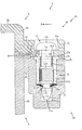
図8は、基板ボックス1を封印した状態におけるボックス封印具10の部分断面図であり、図中の矢印Aはボックスカバー3のスライド方向を示している。図8に示すように、上述したナット12および係止座金13は、封印部材21の内部に配置されており、ナット12の円筒部12bの下方にストッパ材13が配置されている。ナット12のめねじ部12cの内径は、封印ねじ11の非おねじ部11eの外径と比較して大きく形成されており、めねじ部12c内に非おねじ部11eを挿設することができる。また、保持穴12eは、めねじ部12cと連通して穿設されており、その内径は封印ねじ11のおねじ部11dの外径より大きく形成されている。よって、封印ねじ11がナット12のめねじ部12cに螺入されて基板ボックス1が封印された場合、封印ねじ11のおねじ部11dを保持穴12e内に挿設することができる。
【0086】
封印部材21の内部には、内径の異なる複数の同心状の嵌合穴21a,21b,21cが連通してそれぞれ形成されており、これらの内径は嵌合穴21a,21b,21cの順に大きく形成されている。嵌合穴21aは、封印部材21の上面に形成されており、ナット12のナット頭部12aが嵌合可能に形成されている。この嵌合穴21aの深さ、即ち、封印部材21の上面から嵌合穴21aの底面までの長さはナット12のナット頭部12aの厚さ(軸方向長さ)と略同一に形成されている。よって、嵌合穴21aに嵌合されたナット12の上端部が封印部材21の上面から突出することを防止することができる。従って、ボックスカバー3をボックスベース2に対して矢印A方向へスライドさせる際に、封印部材31の下面部分がナット12の上端部分に引っ掛かることが防止されるので、ボックスカバー3を滑らかにスライドさせて、封印部材21,31を合致させることができる。
【0087】
嵌合穴21bは、嵌合穴21aに連通して形成されており、ナット12の円筒部12bが嵌合可能に形成されている。この嵌合穴21bの深さ、即ち、嵌合穴21aの底面から嵌合穴21bの底面までの長さは、ナット12の円筒部12bの軸方向長さより大きく形成されており、円筒部12bの下面と嵌合穴21bの底面との間に係止座金13を保持する空間を形成することができる。また、嵌合穴21bと嵌合穴21cとの連結部分には、面取り部Cが形成されており、係止座金13の受け部13aが嵌合される。よって、係止座金13は、面取り部Cを介して嵌合穴21bの底面に位置決めされるとともに、ナット12の円筒部12b下面により押さえ付けられることがない。従って、係止座金13の内孔13b内に封印ねじ11の先端部11cを容易に挿入することができるとともに、係止座金13を容易に弾性変形させることができる。
【0088】
嵌合穴21cは、嵌合穴21bに連通して形成されており、封印ねじ11の先端部11cが嵌合可能に形成されている。この嵌合穴21cの深さ、即ち、嵌合穴21bの底面から嵌合穴21cの底面までの長さは、封印ねじ11の先端部11cの軸方向長さより大きく形成されており、嵌合穴21cの底面に封印ねじ11の先端部11c下面を当接させてしまうことがない。
【0089】
また、上述した封印部材31の挿入穴31bの内径は、封印ねじ11の頭部11bの外径より小さく形成されるとともに、封印ねじ11のおねじ部11dの外径より大きく形成されている。よって、封印ねじ11のおねじ部11dを挿入穴31bを貫通させて、ナット12のめねじ部12cに螺合させることができる。また、封印ねじ11の係止溝11fが係止座金13により係止されて封印ねじ11が封印部材21内に取り外し不可能な状態で保持された場合、封印ねじ11の頭部11bは係合穴31a内に係合される。従って、封印部材21,31は封印ねじ11により分離不可能に連結され、基板ボックス1は開封不可能な状態で封印することができるのである。
【0090】
図8に示すように、封印部材21,31が対向しつつ合致され封印ねじ11により連結された場合、封印部材21の上面部分に凸設された周壁24は、封印部材31の下面部分に凹設された嵌合溝35に填り込み、封印部材31の下面部分に凸設された周壁34は、封印部材21の上面部分に凹設された嵌合溝25に填り込んでいる。よって、封印部材21,31の当接面の間、即ち、周壁24と嵌合溝35との当接面の間、又は、周壁34と嵌合溝25との当接面の間へ薄板状の工具等を差し込み、封印ねじ11をナット12および係止座金13ごと封印部材21から引き抜き、基板ボックス1を開封しようとしても、薄板状の工具等の先端部分が周壁24,34又は嵌合溝25,35に引っ掛かるので、その差し込みを防止することができる。
【0091】
例えば、図8の右側部分における嵌合溝25と周壁34との当接面の間へ薄板状の工具等を差し込んで、封印ねじ11をナット12および係止座金13ごと封印部材21から引き抜き、基板ボックス1を開封しようとしても、薄板状の工具等の先端部分が嵌合溝25に当たるので、薄板状の工具等の差し込みを防止することができる。従って、基板ボックス1のこじ開けが防止されて、基板ボックス1に収納された主制御基板7からROM等を取り外して交換し、パチンコ機Pの遊技内容を変更する不正行為を防止することができるのである。
【0092】
図9は、予備ねじ14を保持した状態におけるボックス封印具10の部分断面図である。図9に示すように、上述した予備ねじ保持部材23の予備ねじ保持穴23aは、予備ねじ保持部材23の上端面側の内径(上端側内径)より、予備ねじ保持部材23の下端面側の内径(下端側内径)を小さくしたテーパ部T2を有しており、その上端側内径は、予備ねじ14のおねじ部11dの外径と比較して大きく形成されている。よって、このテーパ部T2を介して、予備ねじ14を予備ねじ保持穴23a内へ容易に挿入することができる。また、予備ねじ保持穴23aの下端側内径は、予備ねじ14のおねじ部11dの外径と比較して小さく形成されている。よって、予備ねじ14を予備ねじ保持穴23aへ挿入した場合、予備ねじ14の頭部11bの下端面と予備ねじ保持部材23の上端面とが当接するまで、予備ねじ14が押し込まれると、予備ねじ保持穴23aの下端部分と予備ねじ14のおねじ部11dとが係合して、予備ねじ14を予備ねじ保持穴23a内に取り外し可能な状態で保持することができる。
【0093】
また、上述した封印部材31の予備ねじ保持板33は、予備ねじ保持部材23に保持された予備ねじ14の頭部11bの上方に覆設されており、予備ねじ保持板33の下面と予備ねじ14の頭部11bの頂部とは当接している。よって、予備ねじ14の頭部11bは予備ねじ保持板33により押さえられているので、予備ねじ14の抜け落ちが防止され、予備ねじ14の紛失を防止することができる。また、予備ねじ保持部材23に保持された予備ねじ14の頭部11bを掴んで、予備ねじ14を上方へ抜き取る不正行為等を防止することができる。尚、図9中の矢印Aはボックスカバー3のスライド方向を示している。
【0094】
次に、上記のように構成された基板ボックス1による主制御基板7の収納方法について説明する。まず、ボックスカバー3の仕切部材5形成側面(図2の手前側面)と主制御基板7の部品面71側(図2の裏側面)とを対向させて、主制御基板7の位置決め穴7g,7gに位置決め部材4,4の位置決め突起4a,4aを対向させる一方、主制御基板7の位置決め穴7h,7hに位置決め部材6,6の位置決め突起6a,6aを対向させる。その後、主制御基板7の位置決め穴7g,7gに位置決め突起4a,4aをそれぞれ嵌合させる一方、主制御基板7の位置決め穴7h,7hに位置決め突起6a,6aをそれぞれ嵌合させて、主制御基板7をボックスカバー3及び仕切部材5の所定位置に位置決めする。
【0095】
この位置決め部材4,4,6,6による位置決めに伴って、主制御基板7は、そのコネクタ7b〜7fが仕切部材5のコネクタ口5d〜5hに挿嵌され、その部品面71におけるコネクタ7b〜7fの配置側縁部(図2の左側)が、長手方向(図2の上下方向)全域に亘って仕切部材5の覆設板5bにより覆われる(図4参照)。よって、かかる仕切部材5の覆設板5bにより主制御基板7におけるコネクタ7b〜7f配置側縁部への接触行為を防止することができるのである。
【0096】
一方、ボックスベース2の側壁2b,2cにそれぞれ配設された各封印部材21の嵌合穴21b内に係止座金13を挿入し、その後、ナット12を嵌合穴21a,21b内にそれぞれ嵌合させる。また、各封印ユニット20の各封印部材21に設けられた予備ねじ保持穴23a内に予備ねじ14をそれぞれ挿入する。各予備ねじ14が各予備ねじ保持穴23a内に完全に挿入された後、ボックスカバー3の主制御基板7側面にボックスベース2を対向させる。
【0097】
ボックスベース2をボックスカバー3に対向させた後、ボックスカバー3の各係止爪3d1の先端部分をボックスベース2の各係止枠2e1の各係止溝2e2へ挿入して、各係止枠2e1に係止爪3d1を係止して、ボックスベース2とボックスカバー3との互いの開口面を合致させる。この合致により、ボックスベース2の底板2aに対してボックスカバー3の天板3aが対向されて、ボックスベース2にボックスカバー3が覆設され、ボックスベース2の収容空間2d内に主制御基板7が収容される。この収容により、主制御基板7は、位置決め部材4,6とボックスベース2のスペーサ2a1〜2a5との間に挟み込まれる。
【0098】
ここで、ボックスカバー3がボックスベース2に覆設されると、ボックスカバー3の各遮蔽板3d2がボックスベース2の側壁板2eの内側に入り込み、各遮蔽板3d2によって、側壁板3dと側壁板2eとの対向面間、即ち、合わせ目が遮蔽される。
【0099】
また、ボックスカバー3とボックスベース2とが合致され、かつ、ボックスカバー3が矢印A方向へスライドされる以前の状態では、図3に示すように、収容空間2dの側壁板2cとその側壁板2cと対向する主制御基板7端部(図3の下側端)との間に空隙L3が設けられる一方、ボックスベース2の各係止枠2e1におけるボックスカバー3のスライド方向側(図3の下側)に設けられた各制限壁2e3と各係止溝2e2に係止されたボックスカバー3の各係止爪3d1との間には、係止爪3d1と係止溝2e2の長手方向における差分長さ分の空隙w4(=w1−w2)が設けられる。
【0100】
ボックスカバー3は、これらの空隙L3,w4を介して、ボックスベース2及びボックスカバー3の合致後、ボックスベース2に対して相対的に矢印A方向へ向けてスライドされるのである。かかる場合に、収容空間2d内に収容された主制御基板7は、その位置決め穴7g,7g,7h,7hに位置決め部材4,4,6,6の各位置決め突起4a,4a,6a,6aが嵌合されボックスカバー3に引っ掛けられているので、ボックスカバー3のスライドに伴って、スペーサ2a1〜2a5との当接しつつ収容空間2d内をスライドされる。
【0101】
ボックスカバー3は、その各係止爪3d1が各係止溝2e2内を矢印A方向へ向けて摺動することに伴って、ボックスベース2に対して矢印A方向へスライドされる。かかるスライドを続けると、各係止爪3d1は、が各係止溝2e2内を矢印A方向へ向けて空隙w4の長さ分摺動され、各係止枠2e1の各制限壁2e3と当接して摺動位置が制限されて、ボックスカバー3のスライドが停止される。一方、ボックスカバー3のスライドに伴って、ロック板2g,3eが結合板3f,2hの結合口3g,2iにそれぞれ挿入され、ロック板2g,3eが結合板3f,2hに係止されてボックスベース2とボックスカバー3とが結合される。
【0102】
また、ボックスカバー3が矢印A方向へスライドされると、封印部材21に凸設された周壁24は、封印部材31に凹設された嵌合溝35に填り込み、封印部材31に凸設された周壁34は、封印部材21に凹設された嵌合溝25に填り込み、封印部材21,31が合致される。
【0103】
このように合致された封印部材21,31によれば、その当接面(対向面)の間、即ち、周壁24と嵌合溝35との当接面の間、又は、周壁34と嵌合溝25との当接面の間へ薄板状の工具等を差し込み、封印ねじ11がナット12および係止座金13ごと封印部材21から引き抜き基板ボックス1を開封しようとしても、薄板状の工具等の先端部分が周壁24,34又は嵌合溝25,35に引っ掛かるので、その差し込みが防止される。一方、封印部材21,31が合致されると、各予備ねじ保持板33は、各予備ねじ保持部材23に保持された各予備ねじ14の頭部11b上方に覆設される。
【0104】
ボックスベース2とボックスカバー3とが結合され、封印部材21,31が合致された後、ボックスカバー3に穿設された各通穴5c,5cにビス9,9をそれぞれ挿入すると、これらのビス9,9のねじ部先端が主制御基板7の各通穴7a,7aを通過してボックスベース2の底板2aに到達する。各ビス9,9のねじ部先端の底板2aへの到達後、各ビス9,9がボックスベース2の底板2aにねじ込まれ、仕切部材5を介してボックスカバー3及び主制御基板7をボックスベース2にまとめてねじ止めにより固定される。その後、各通穴5c,5cから底板2aにねじ込まれたビス9,9を覆いつつ、ボックスベース2及びボックスカバー3に跨るようにして、封印シール10,10がそれぞれ貼付される(図4参照)。
【0105】
次に、図4に示すように、各ボックス封印具10の封印部材31のうち、ボックスカバー3の側壁3bの最も左側に配設された封印部材31、及び、ボックスカバー3の側壁3cの最も右側に配設された封印部材31の内部へ封印ねじ11を挿入する。具体的には、図8に示すように、上述した2つの封印部材31の各挿入穴31b内に封印ねじ11の先端部11cをそれぞれ挿入する。封印ねじ11挿入後、封印ねじ11の係合溝11gにスクリュードライバ等のねじ回し工具を係合し、封印ねじ11をナット12にねじ込む。封印ねじ11がねじ込まれると、封印ねじ11のおねじ部11dは、ナット12のめねじ部12cに螺入される。封印ねじ11のねじ込みが続行されると、封印ねじ11の先端部11cは、ナット12の下方に配置された係止座金13の受け部13aに到達し、内孔13bへと案内される。封印ねじ11の先端部11cが内孔13bへ案内され挿入されると、先端部11cのテーパ部T1により、係止座金13の内孔13aが押し広げられ、係止座金13の受け部13aが弾性変形する。
【0106】
封印ねじ11が更にねじ込まれると、封印ねじ11のおねじ部11dとナット12のめねじ部12cとの螺合が解除され、おねじ部11dおよび非おねじ部11eはそれぞれ保持穴12eおよびめねじ部12c内に挿設され、封印ねじ11の係止溝11fが係止座金13により係止され、封印ねじ11が封印部材21内にて抜き取り不可能な状態で保持される。一方、封印ねじ11の頭部11bは、封印部材31の係合穴31a内に係合される。
【0107】
その結果、封印ねじ11を反ねじ込み方向へ回転させた場合、封印ねじ11のおねじ部11dは、ナット12の保持穴12e内にて空回し、封印ねじ11を封印部材21内から抜き取り不可能にすることができる。更に、封印ねじ11の頭部11bは、封印部材31の係合穴31aに係合されているので、基板ボックス1のボックスベース2とボックスカバー3とが開封不可能に連結され、基板ボックス1を確実に封印することができる(図8参照)。よって、基板ボックス1に被包された主制御基板7の制御用ROM等を不適法に取り外して、パチンコ機Pの遊技内容を変更する不正行為を防止することができる。また、封印部材21,31を破壊、切断等すれば基板ボックス1を開封することができるが、その場合には、基板ボックス1が開封された痕跡を確実に残すことができる。即ち、不正行為が行われたか否かを即座に発見することができる。
【0108】
また、このようにして基板ボックス1が封印されると、各予備ねじ保持穴23aに保持された各予備ねじ14は、各予備ねじ保持板33により、確実に係止され、各予備ねじ保持穴23a内に抜き取り不可能な状態で保持される。よって、予備ねじ14が予備ねじ保持穴23aから抜け落ちることが防止されるので、予備ねじ14の紛失を防止することができる。また、予備ねじ14の不正な抜き取りを防止することができる。
【0109】
以上説明したように、本実施例の基板ボックス1によれば、各係止枠2e1及び各係止爪3d1によって、ボックスベース2の側壁板2eとボックスカバー3の側壁板3dとは連結されている。よって、かかる側壁板2e,3dの対向面間へ薄板状の工具等を差し込んでこじ開けようとしても、こじ開ける際の持ち上げ量を各係止枠2e1及び各係止爪3d1により制限することができる。従って、かかる持ち上げ量の制限により、ボックスベース2の側壁板2eと側壁板3dとの対向面間に隙間が開くことを防止することができるのである。
【0110】
ここで、例えば、側壁板2e,3dの対向面がそれぞれ略平面状に形成されていると、かかる対向面間から薄板状の工具等が差し込まれて、その工具等の先端部分で主制御基板7の信号線が削られ切断され、遊技内容が不正に変更されてしまう。
【0111】
しかしながら、基板ボックス1では、各係止枠2e1及び各係止爪3d1によってボックスベース2とボックスカバー3とが連結される箇所、即ち、側壁板2e,3dの対向面間を、遮蔽板3d2によって遮蔽している。よって、かかる側壁板2e,3dの対向面間へ薄板状の工具等が差し込まれたとしても、その工具等の先端は遮蔽板3d2に突き当たるので、かかる工具等の差し込みを防止することができる。
【0112】
この差し込みの防止によりボックスベース2及びボックスカバー3のこじ開けが防止されるので、こじ開けられた基板ボックス1の隙間から薄板状の工具や針金等を差し込んで主制御基板7に不正な加工を施し、パチンコ機Pの遊技内容を変更する不正行為を防止することができる。
【0113】
また、各遮蔽板3d2は、略平板状に形成され、且つ、ボックスカバー3の側壁板3dの端面における各係止爪3d1の間部分にそれぞれ立設されるので、各係止爪3d1とともに側壁板3dと側壁板2eとの対向面間をほぼ全域に亘って遮蔽することができる。
【0114】
更に、遮蔽板3d2は、ボックスカバー3の側壁板3dに一体的に立設されるので、かかる側壁板3dとボックスベース2の側壁板2eとの対向面間を封印シールなどの他の部材を用いて塞がなくても、かかる対向面間に生じる間隙を遮蔽することができる。よって、封印シールなどを別途、側壁板3dとボックスベース2の側壁板2eとの対向面間に貼り付ける必要がないので、その分、基板ボックス1の組立作業を簡素化することができる。また、上記の通り、余分な封印シールが不要なので、基板ボックス1の部品点数がされて、その分、基板ボックス1に要するコストを低減することができる。
【0115】
以上、実施例に基づき本発明を説明したが、本発明は上記実施例に何ら限定されるものではなく、本発明の趣旨を逸脱しない範囲内で種々の改良変形が可能であることは容易に推察できるものである。
【0116】
例えば、ボックスベース2の側壁板2e及びボックスカバー3の側壁板3dにおける対向面間は、複数枚の遮蔽板3d2によって遮蔽されたが、遮蔽板3d2の枚数は必ずしもこれに限られるものではなく、例えば、遮蔽板は、側壁板3dの端面の全域に亘って連続した1枚の板状体に形成しても良い。この遮蔽板によれば、側壁板2e,3dの合わせ目の全域を遮蔽して、薄板状の工具等の差し込みをより一層防止することができる。
【0117】
本実施例では、ボックスカバー3の側壁板3dに遮蔽板3dを立設したが、例えば、ボックスベース2の側壁板2eに遮蔽板を立設しても良い。即ち、ボックスベース2の側壁板2eとボックスカバー3の側壁板3dとの合わせ目を遮蔽することができれば、遮蔽板は、ボックスベース又はボックスカバーのいずれに設けても良い。また、本実施例では、ボックスカバー3の側壁板3dに遮蔽板3dを立設したが、例えば、遮蔽板をボックスカバーと別体に形成しても良い。
【0118】
更に、本実施例では、側壁板2e,3d、遮蔽板3d2及び段部3d3の合わせ目を合决り状に接合したが、かかる接合部分の合わせ目の形状は、必ずしもこれに限られるものではなく、例えば、斜め矧ぎ(ななめはぎ)、本実矧ぎ(ほんざねはぎ)、相互矧ぎ(そうごはぎ)又は矢はず矧ぎ(やはずはぎ)などの板矧ぎ(いたはぎ)形状に構成しても良い。
【0119】
本実施例では、主制御基板7を収容する基板ボックス1に本発明を適用したが、遊技機に配設される他の回路基板、例えば、球の払い出しの制御を行う払い出し制御基板などを収容する基板ボックスに本発明を適用しても良い。
【0120】
なお、以下に本発明の変形例を示す。請求項1記載の遊技機用基板ボックスにおいて、前記側壁部材を、その側壁部材に対向する前記ボックスベース又はボックスカバーの他方における縁部に連結し、そのボックスカバーを前記ボックスベースに対して開閉可能に結合する開閉部材を備え、前記遮蔽部材は、その開閉部材により結合される前記側壁部材と前記ボックスベース又はボックスカバーの他方における縁部との対向面間を遮蔽するものであることを特徴とする遊技機用基板ボックス1。
【0121】
遊技機用基板ボックス1によれば、開閉部材によって、側壁部材とボックスベース又はボックスカバーの他方における縁部とは連結されるので、かかる両者の対向面間へ薄板状の工具等を差し込んでこじ開けようとしても、こじ開ける際の持ち上げ量を開閉部材により制限できる。よって、かかる持ち上げ量の制限により、側壁部材とボックスベース又はボックスカバーの他方との対向面間に隙間が開くことを防止することができる。
【0122】
ここで、例えば、開閉部材により連結された側壁部材とボックスベース又はボックスカバーの他方における縁部との対向面がそれぞれ略平面状に形成されていると、かかる対向面間から薄板状の工具等を差し込まれてしまう。かかる工具等が差し込まれると、その工具等の先端部分で回路基板の信号線が削られ切断されて、遊技内容が不正に変更されてしまうおそれがある。
【0123】
しかしながら、遊技機用基板ボックス1によれば、遮蔽部材によって、側壁部材とボックスベース又はボックスカバーの他方における縁部との対向面間は遮蔽されるので、かかる対向面間へ薄板状の工具等が差し込まれたとしても、その工具等の先端は遮蔽部材に突き当たるので、かかる工具等の差し込みを防止することができるのである。
【0124】
請求項1記載の遊技機用基板ボックス、又は、遊技機用基板ボックス1において、前記ボックスベース又はボックスカバーの他方は、前記側壁部材と対向する位置からその側壁部材へ向けて立設される第2側壁部材を備え、前記遮蔽部材は、前記側壁部材から前記ボックスベース又はボックスカバーの他方側へ向けて立設されるとともに、前記第2側壁部材における前記側壁部材との対向面より更に前記ボックスベース又はボックスカバーの他方側へ延出されていることを特徴とする遊技機用基板ボックス2。
【0125】
この遊技機用基板ボックス2によれば、ボックスカバーがボックスベースの開放部分に覆設される場合、側壁部材から立設される遮蔽部材は、第2側壁部材における側壁部材との対向面より更にボックスベース又はボックスカバーの他方側へ延出され、この延出部分により側壁部材と第2側壁部材との対向面間を遮蔽することができる。よって、ボックスベース及びボックスカバーをこじ開けるために、薄板状の工具等が第1及び第2側壁部材の対向面間へ差し込まれたとしても、その工具等の先端は遮蔽部材の延出部分に突き当たるので、薄板状の工具等の差し込みを防止して、ボックスベース及びボックスカバーのこじ開けを防止することができる。
【0126】
遊技機用基板ボックス2において、前記第2側壁部材における前記側壁部材との対向面は、その側壁部材における前記第2側壁部材との対向面と当接されており、前記遮蔽部材は、前記第2側壁部材の立設位置より内側位置へ向けて立設され、その遮蔽部材の外側面は前記第2側壁部材の内側面と当接されていることを特徴とする遊技機用基板ボックス3。よって、側壁部材と第2側壁部材との対向面間、及び、遮蔽部材の外側面と第2側壁部材の内側面との間に隙間ができることがない。従って、このような隙間に薄板状の工具等を差し込んで、ボックスベース及びボックスカバーをこじ開ける不正行為を防止することができる。
【0127】
請求項1記載の遊技機用基板ボックス、又は、遊技機用基板ボックス1から3のいずれかにおいて、前記遮蔽部材は、略板状に形成されるとともに、前記ボックスベース又はボックスカバーの縁部に沿って所定長さ連続して設けられていることを特徴とする遊技機用基板ボックス4。
【0128】
請求項1記載の遊技機用基板ボックス、又は、遊技機用基板ボックス1から4のいずれかにおいて、前記遮蔽部材は前記ボックスベース又はボックスカバーのいずれか一方に一体的に形成されていることを特徴とする遊技機用基板ボックス5。
【0129】
請求項1記載の遊技機用基板ボックス、又は、遊技機用基板ボックス1から4のいずれかにおいて、前記遮蔽部材は前記ボックスベースおよびボックスカバーと別体に形成されていることを特徴とする遊技機用基板ボックス6。
【0130】
【発明の効果】
本発明の遊技機によれば、遊技機用基板ボックスは、ボックスカバーとボックスベースとを対向させてから相対的に所定量スライド移動させることで、第2係合手段の係止面がボックスカバーの天板部方向への第1係合手段の係合面の移動を抑制するように第1係合手段と第2係合手段とが係合し、その係合状態の遊技機用基板ボックスの第1封印手段と第2封印手段とにスライド移動方向とは交差する方向から封印ネジを挿入することで封止される。よって、遊技機用基板ボックスは、第1封印手段、第2封印手段および封印ネジにより封止されるだけでなく、第2係合手段によりボックスカバーの天板部方向への第1係合手段の移動が抑制されるので、ボックスベース及びボックスカバーをこじ開けるために、薄板状の工具等がボックスベース又はボックスカバーの間へ差し込まれることを防止することができる。この差し込みの防止によりボックスベース及びボックスカバーのこじ開けが防止されるので、こじ開けにより生じる隙間から薄板状の工具や針金等を差し込んで、回路基板に不正な加工を施し、遊技機の遊技内容を変更する不正行為を防止することができるという効果がある。
【図面の簡単な説明】
【図1】 本発明の一実施例である基板ボックスが配設されたパチンコ機の裏面図である。
【図2】 基板ボックスの分解斜視図である。
【図3】 ボックス本体に合致されたボックス蓋体がスライドされて結合される以前の状態における基板ボックスの側断面図である。
【図4】 基板ボックスの組立後の外観斜視図である。
【図5】 (a)は、図4のVa−Va線における係止枠及び係止爪の側断面図であり、(b)は、図4のVb−Vb線における遮蔽板の側断面図である。
【図6】 基板ボックスに配設されたボックス封印具の拡大斜視図である。
【図7】 天板を下方へ向けた状態のボックス蓋体の部分的拡大図である。
【図8】 基板ボックスを封印した状態におけるボックス封印具の部分断面図である。
【図9】 予備ねじを保持した状態におけるボックス封印具の部分断面図である。
【符号の説明】
1 主制御基板ボックス(遊技機用基板ボックス)
2 ボックスベース
2g ロック板(第2係合手段)
3 ボックスカバー
3a 天板(天板部)
3d 側壁板(側壁)
3d2 遮蔽板(蔽い板部)
3f 結合板(第1係合手段の一部)
3g 結合口(第1係合手段の一部)
4 位置決め部材(位置決め手段)
5 仕切部材(仕切り手段)
5a 仕切り板(仕切り手段の一部、仕切り側壁部)
5b 覆設板(仕切り手段の一部、覆設部)
7 主制御基板(回路基板)
7b〜7d コネクタ
7g 位置決め穴
11 封印ねじ(封印ネジ)
21 封印部材(第2封印手段)
31 封印部材(第1封印手段)
P パチンコ機(遊技機)
P2 遊技盤
P3 入賞球集合カバー(取付部材)[0001]
BACKGROUND OF THE INVENTION
The present invention is a gaming machineInIn particular, a board box for a gaming machine that can prevent the box base and the box cover from being opened and prevent illegal acts on the circuit board.A gaming machine equipped withIt is about.
[0002]
[Prior art]
In recent years, a gaming machine such as a pachinko machine has been mainly used to control a winning device, a display device, and the like provided on the gaming board to excite the fun of the game. The winning device and the display device are controlled by a logic circuit board on which a large number of electronic components such as IC and LSI are mounted, or a circuit board having a microcomputer. These circuit boards are encapsulated in a board box having a box base and a box cover, and a part of the box base and the box cover of the board box are joined and sealed by a special sealing screw.
[0003]
The sealing screw used for this sealing is formed with a cross-shaped groove on its head so that the tip of the screwdriver tool can be engaged only in the screwing direction. Therefore, when the screwdriver is engaged with the cross groove and rotated in the anti-screwing direction, the screwdriver is idled to prevent the sealing screw from being removed. Accordingly, by sealing the board box with such a sealing screw, the opening of the board box is prevented, so that the act of contacting the circuit board encapsulated in the board box or the ROM is removed from the circuit board and replaced with a game. Unauthorized acts that change the contents are prevented.
[0004]
[Problems to be solved by the invention]
However, in the above-described substrate box, only a part of the box base and the box cover are joined by the sealing screw, and the joint (contact surface) of the box base and the box cover is formed in a substantially flat shape. For this reason, there has been a problem that inserting a thin plate-like tool or the like at the joint between the box base and the box cover opens a gap at the joint between the box base and the box cover, and the substrate box is pry open.
[0005]
When the board box is pry open in this way, a thin plate tool or the like can be inserted through the gap formed at the joint between the box base and the box cover, so the circuit board circuit can be inserted at the tip of the thin plate tool or wire. There is a problem that the game content is illegally changed by cutting and cutting signal lines such as patterns.
[0006]
The present invention has been made in order to solve the above-described problems, and can prevent opening of the box base and the box cover to prevent illegal acts on the circuit board.A gaming machine equipped withThe purpose is to provide.
[0007]
[Means for Solving the Problems]
In order to achieve this object, a gaming machine according to claim 1 is a circuit board on which a control part of the gaming machine and a connector electrically connected to the control part are mounted, a box base, and the box base combined. And a box cover for accommodating the circuit board together with the box base.SquareA board box for a gaming machine, wherein the circuit board includes a control component mounting position in which the control component is disposed, and a connector mounting position in which a connector is disposed on a side edge of the circuit board;, With positioning holesOn the boardFormed into a square shapeThe box cover opposes the control component mounting position in the gaming machine board box containing the circuit board.SquareThe top plate,A side wall extending from the top plate to the box base side, andTop plateSide ofPartitioning means extending from the box base side to the box base, and the circuit boardPositioning means provided with positioning protrusions fitted in the positioning holesAnd first engagement means extending laterally from the box cover and having an engagement surface;Sealing screw can be insertedFirst sealing means, and the partition means is arranged so that the circuit board is separated from the top board portion so as to distinguish the control component mounting position and the connector mounting position in the gaming machine board box containing the circuit board. Standing toward the sideMolded integrally with the box coverA partition side wall portion, and a cover portion that is connected to the partition wall portion, covers a board surface at the connector mounting position, and is provided with a connector opening corresponding to the connector, and the box base includes the box base A second engagement means extending laterally from the base and having a locking surface corresponding to the engagement surface of the first engagement means; and corresponding to the first sealing meansThe sealing screw can be insertedThe gaming machine board box is inserted into the first sealing means and the second sealing means to connect the first sealing means and the second sealing means.Seal screwThe circuit boardThe positioning projection of the positioning means was fitted into the positioning hole ofThe connector disposed at the connector mounting position is exposed from the connector opening,The circuit board is locked to the box cover.,Locked the circuit boardBy making the box cover and the box base face each other and sliding relative to each other by a predetermined amount, the locking surface of the second engagement means moves the first cover toward the top plate of the box cover. The first engagement means and the second engagement means are engaged so as to suppress the movement of the engagement surface of the engagement means, and the first sealing of the gaming machine substrate box in the engaged state Means and the second sealing means from a direction intersecting the slide movement direction.Seal screwIs inserted and sealedThe side wall extending from the side facing the side on which the partition means is provided to the box base side of the side wall is in a state where the box cover and the box base are sealed by the sealing screw. The circuit board extends from the circuit board surface opposite to the connector mounting position to the box base side.The
[0008]
Claim2The gaming machine described is the claim 1RecordIn the gaming machine described above, the gaming machine is a pachinko machine.
[0009]
DETAILED DESCRIPTION OF THE INVENTION
Hereinafter, preferred embodiments of the present invention will be described with reference to the accompanying drawings. FIG. 1 is a back view of a pachinko machine P provided with a main control board box (hereinafter simply referred to as a board box) 1 which is an embodiment of a board box for gaming machines of the present invention. As shown in FIG. 1, a board box 1 is a set of winning balls provided on the back surface of a game board P2 of a pachinko machine P which is a kind of game machine, by a thin dish-like mounting member P1 made of a thin steel plate or the like. It is attached to the cover P3.
[0010]
The board box 1 is for encapsulating a main control board 7 (see FIG. 2) on which electronic components (control parts) such as ROM storing a control program and data related to the game contents of the pachinko machine P are mounted. , Mainly, a box base 2 and a box cover 3 covering the box base 2 are provided.
[0011]
FIG. 2 is an exploded perspective view of the substrate box 1, and an arrow A in FIG. 2 slides the box cover 3 relative to the box base 2 in order to couple the box cover 3 to the box base 2. Shows direction. In FIG. 2, the illustration of the spacer 2a4 and the spacer 2a5 is omitted.
[0012]
As shown in FIG. 2, the box base 2 and the box cover 3 of the substrate box 1 are both formed in a substantially rectangular bowl-like body, and the box base 2 is formed so as to be able to accommodate (install) a main control board 7 described later. Has been. According to this substrate box 1, with the main control substrate 7 (described later) housed (installed) in the box base 2, the opening surfaces (open portions) of the box base 2 and the box cover 3 face each other and are matched (unioned). ), The box cover 3 is covered with the box base 2, and the main control board 7 can be encapsulated. In FIG. 2, the box cover 3 is seen from the back surface (rear surface) side, and the electronic components mounted on the component surface 71 (back side surface in FIG. 2) of the main control board 7 are omitted. .
[0013]
The box base 2 has a substantially rectangular flat plate-like bottom plate 2a on which a main control board 7 to be described later is installed, and a substantially flat plate that is erected on the four end sides of the bottom plate 2a (to the front side of the paper surface of FIG. 2). Shaped side wall plates 2b, 2c, 2e, 2f. The end portions of these side wall plates 2b, 2c, 2e, 2f are connected in series so as to have a square shape in plan view, and the box base 2 has these five bottom plates 2a, side wall plates 2b, 2c, 2e. , 2f are formed into a substantially rectangular bowl having an open portion on one surface. Further, the sealing units 20 of the box sealing device 10 for sealing the substrate box 1 are disposed on the outer surfaces of the side wall plates 2b and 2c, respectively. The sealing unit 20 of the box sealing tool 10 will be described later.
[0014]
Inside the box base 2, an accommodation space 2d, which is a substantially concave space for accommodating the main control board 7, is provided. The accommodation space 2d has a width in the longitudinal direction (vertical direction in FIG. 2), that is, the width between the opposing surfaces of the side wall plates 2b and 2c, formed in the width L1, and the longitudinal direction of the main control board 7 (FIG. 2). (L1> L2). Moreover, the direction of the width L1 in the accommodation space 2d and the direction of the width L2 in the main control board 7 coincide with the sliding direction of the box cover 3 (arrow A direction in FIG. 2).
[0015]
The side wall plate 2e is erected corresponding to the side wall plate 3d of the box cover 3, and when the box cover 3 is covered by the box base 2, the left side surface of the substrate box 1 together with the side wall plate 3d (FIG. 2). And the left side of FIG. The side wall plate 2e is provided with four locking frames 2e1 formed in a rectangular frame shape having substantially the same shape. Each locking frame 2e1 locks four locking claws 3d1 of the box cover 3 described later so as to be rotatable and slidable. By this locking, the side wall plate 2e of the box base 2 and the box cover 3 are locked. The box cover 3 can be connected to the box base 2 so as to be openable and closable.
[0016]
The respective locking frames 2e1 are provided at substantially equal intervals in the longitudinal direction of the bottom plate 2a (the vertical direction in FIG. 2) in the side wall plate 2e, and the interval between the respective locking frames 2e1 is set to an interval width t1. Each locking frame 2e1 is provided with a locking groove 2e2 into which each locking claw 3d1 can be inserted. Each of these locking grooves 2e2 is provided so that four locking claws 3d1 of the box cover 3 to be described later are slidably locked in the longitudinal direction of the box base 2, so that the longitudinal direction of the box base 2, that is, The bottom plate 2a is formed in a long groove shape having a width in the longitudinal direction of the width w1.
[0017]
Moreover, restriction walls 2e3 for restricting the sliding positions of the respective locking claws 3d1 of the box cover 3 are provided at both ends in the longitudinal direction (the vertical direction in FIG. 2) of the respective locking grooves 2e2. Therefore, when the box cover 3 slides relative to the box base 2 by these restricting walls 2e3, the sliding amount of each locking claw 3d1 of the box cover 3 is restricted, and the relative Is controlled.
[0018]
The side wall plate 2 f is erected corresponding to the partition member 5 of the box cover 3, and when the box cover 3 is covered by the box base 2, the side wall plate 2 f together with the partition member 5 and the right side surface (FIG. 2). And the right side of FIG. Further, the side wall plate 2 f includes a lead-out port 2 f 1 for leading a cable (wiring member) connected to the main control board 7 housed in the board box 1.
[0019]
Also, a substantially cylindrical spacer 2a1 projects from the corner of the connecting portion of the side wall plates 2c, 2e on the front surface of the bottom plate 2a (lower left side in FIG. 2), and the side wall plate 2c side (FIG. 2) on the front surface of the bottom plate 2a. A substantially plate-like spacer 2a2 is provided so as to project over the bottom plate 2a and the side wall plate 2c at a substantially central portion of the lower edge. Further, on the front surface of the bottom plate 2a, a substantially plate-like spacer 2a3 is erected on the edge of the side wall plate 2f (right side in FIG. 2) in the longitudinal direction (vertical direction in FIG. 2) of the bottom plate 2a. Yes.
[0020]
A rectangular lock plate 2g is provided on the side wall 2b of the box base 2 so as to project outward (upward in FIG. 2), while the side wall 2c of the box base 2 locks a box cover 3 to be described later. A rectangular flat plate-like coupling plate 2h on which the plate 3e is locked is provided. The coupling plate 2h is provided with a coupling port 2i into which a lock plate 3e described later can be inserted. When the box cover 3 fitted to the box base 2 is slid in the direction of arrow A, the coupling plate 2h is locked to the coupling port 2i. A plate 3e can be inserted.
[0021]
As a result, the lock plate 3e of the box cover 3 is locked to the coupling plate 2h of the box base 2, and the box base 2 and the box cover 3 are coupled. Thus, in this coupled state, the box cover 3 is secured to each locking frame 2e1. In addition, it can be prevented from being rotated and released via the respective locking claws 3d1 described later.
[0022]
The box cover 3 has a substantially flat top plate 3a that covers the opening surface (front side of FIG. 2) of the box base 2 so as to face the bottom plate 2a of the box base 2, and the longitudinal direction of the top plate 3a (FIG. 2). Side wall plates 3b and 3c erected at both ends in the vertical direction), and a side wall plate 3d inclined outward from one side edge (right side in FIG. 2) of the top plate 3a. Sealing units 30 are arranged on the side wall plates 3b and 3c of the box cover 3 so as to face the above-described sealing unit 20 in order to seal the substrate box 1. The sealing unit 30 of the box sealing tool 10 will be described later.
[0023]
The side wall plate 3d of the box cover 3 extends while being inclined from one side edge (right side in FIG. 2) of the top plate 3a, and the end surface (front side surface in FIG. 2) of the extended portion of the side wall plate 3d. The four locking claws 3d1 are provided at substantially equal intervals corresponding to each locking frame 2e1 described above. The front end portions of the respective locking claws 3d1 are bent in a substantially J shape, and the front end portions of the locking claws 3d1 are formed so as to be inserted into the locking grooves 2e2 of the locking frame 2e1. By inserting the locking claw 3d1 into the locking groove 2e2, each locking claw 3d1 is locked to each locking frame 2e1. In addition, the longitudinal width of each locking claw 3d1 is formed to have a width length w2, and is narrower than the width length w1 of each locking groove 2e2 (w1> w2).
[0024]
A plurality of (for example, three) substantially flat shielding plates 3d2 are provided at the end surface (front side surface in FIG. 2) of the extending portion of the side wall plate 3d and between the above-described locking claws 3d1. It is erected integrally. When the box cover 3 is covered with the box base 2, the plurality of shielding plates 3d2 shields and closes the opposing surfaces (joints) between the side wall plate 3d and the side wall plate 2e (FIG. 5). (See (b)). In addition, the width in the longitudinal direction (vertical direction in FIG. 2) of each shielding plate 3d2 is formed to be a width length w3, and the width length w3 of each shielding plate 3d2 is formed to be narrower than the interval width t1 of each locking frame 2e. (W3 <t1).
[0025]
Further, a rectangular plate-like lock plate 3e is projected outward (downward in FIG. 2) on the side wall plate 3c of the box cover 3, while the above-described box base 2 is provided on the side wall plate 3b of the box cover 3. A rectangular flat plate-like coupling plate 3f on which the lock plate 2g is locked is provided. The coupling plate 3f has a coupling port 3g into which the lock plate 2g described above can be inserted. When the box cover 3 matched with the box base 2 is slid in the direction of arrow A, the coupling plate 3f is locked to the coupling port 3g. A plate 2g can be inserted. As a result, the lock plate 2g of the box base 2 is locked to the coupling plate 3f of the box cover 3, and the box base 2 and the box cover 3 are coupled. Thus, in this coupled state, the box cover 3 is secured to each locking frame 2e1. In addition, it can be prevented from being rotated and released via the respective locking claws 3d1 described later.
[0026]
A substantially L-shaped inner wall plate 3 h is formed adjacent to the inner side surface of the side wall plate 3 c of the box cover 3. The inner wall plate 3h is erected from the top plate 3a toward the main control board 7 side (the front side in FIG. 2), and its end portion is formed so as to protrude from the end portion of the side wall plate 3c. For this reason, when the box cover 3 is covered with the box base 2, the end of the inner wall plate 3 h protrudes from the front end of the side wall plate 2 c of the box base 2 toward the bottom plate 2 a.
[0027]
Therefore, when the box cover 3 covered on the box base 2 is slid in the direction of arrow A, the end of the inner wall plate 3h can be hooked on the front end of the side wall plate 2c of the box base 2. As described above, the inner wall plate 3h is hooked on the side wall plate 2c, whereby the sliding of the box cover 3 in the direction of arrow A can be stopped, and the box cover 3 can be surely matched with the box base 2.
[0028]
3 is a side sectional view of the substrate box 1 in a state before the box cover 3 fitted to the box base 2 is slid and joined. An arrow A in FIG. 3 indicates that the box cover 3 is connected to the box base 2. The direction in which the box cover 3 is slid relative to the box base 2 is shown. In FIG. 3, the spacer 2a3 is omitted.
[0029]
As shown in FIG. 3, columnar spacers 2a4 project from the corners (upper side in FIG. 3) of the side wall plates 2b and 2e on the front surface of the bottom plate 2a, and the side wall plate 2b side on the front surface of the bottom plate 2a. A substantially plate-like spacer 2a5 projects from the edge across the bottom plate 2a and the side wall plate 2b. The spacer 2a4 protrudes vertically symmetrically with the spacer 2a1, and the spacer 2a5 protrudes vertically symmetrically with the spacer 2a2.
[0030]
When the main control board 7 is accommodated in the box base 2, the spacers 2 a 1 to 2 a 5 abut against the edge of the main control board 7 on the solder surface 72 side (front side in FIG. 2) to support the main control board 7. Thus, a gap is provided between the main control board 7 and the bottom plate 2a to prevent contact between the solder surface 72 and the bottom plate 2a.
[0031]
Therefore, when the main control board 7 is slid together with the box cover 3 in the accommodation space 2d, a gap is provided between the main control board 7 and the bottom plate 2a from the solder surface 72 of the main control board 7 toward the bottom plate 2a. Since connecting pins (not shown) such as protruding electronic components are prevented from being caught on the bottom plate 2a, the main control board 7 can be smoothly slid in the accommodation space 2d. Moreover, these spacers 2a1 to 2a5 have substantially the same protruding height from the bottom plate 2a, and can accommodate the main control board 7 in the accommodation space 2d without rattling.
[0032]
In a state before the box cover 3 and the box base 2 are matched and the box cover 3 is slid in the direction of arrow A, the side wall plate 2c of the accommodation space 2d and the end of the main control board 7 facing the side wall plate 2c. A gap L3 (= L1−L2) having a difference length between the width length L1 and the width length L2 can be provided between the portion (the lower end of FIGS. 2 and 3). Therefore, by providing the gap L3, the main control board 7 is slid in the direction of the arrow A in the accommodation space 2d as the box cover 3 slides in the direction of the arrow A, as will be described later. is there.
[0033]
Further, in each locking groove 2e2 in which each locking claw 3d1 is locked, a gap w4 (= w1-w2) corresponding to the difference length in the longitudinal direction between the locking claw 3d1 and the locking groove 2e2 is provided. ing. Therefore, when each locking claw 3d1 is inserted into the locking groove 2e2, the box cover 3 can be slid in the direction of the arrow A by the gap w4 between the locking groove 2e2 and the locking claw 3d1. . That is, the gap w4 matches the relative slide amount of the box cover 3 with respect to the box base 2.
[0034]
Moreover, the locking groove 2e2 and the clearance w4 of the locking claw 3d1 that match the sliding amount of the box cover 3 with respect to the box base 2 are made smaller than the clearance L3 between the accommodation space 2d of the box base 2 and the main control board 7 described above. (L3> w4). Therefore, when sliding the main control board 7 together with the box cover 3 from the state shown in FIG. 3 by the length of the gap w4 in the direction of arrow A, the opposite end of the main control board 7 to the side wall plate 2c (lower side of FIG. 3). Side) can be prevented from colliding with the side wall plate 2b of the box base 2 and being damaged.
[0035]
In addition, a shielding plate 3d2 is inserted in a portion between each locking frame 2e1, and in this state, a lower end surface (lower side in FIG. 3) of each shielding plate 3d2 and an upper end surface of each locking frame 2e1 opposed thereto. Is provided with a gap w5 (= t1-w3). Moreover, the gap w5 is slightly smaller than the gap w4 (w5 <w4). Therefore, when the main control board 7 is slid by the length of the gap w4 in the arrow A direction together with the box cover 3 from the state shown in FIG. 3, each shielding plate 3d2 collides with each locking frame 2e1 and is damaged. Can be prevented.
[0036]
Further, in the vicinity of both sides in the longitudinal direction of the box cover 3 in the side wall plate 3d described above, a substantially cylindrical positioning member from the top plate 3a side end (left side in FIG. 2) toward the locking claw 3d1 side end (right side in FIG. 2). 4 and 4 are erected. The pair of positioning members 4 and 4 are for positioning a main control board 7 described later at a predetermined position of the box cover 3. The positioning members 4, 4 are integrally formed with the box cover 3, and, like the box cover 3, are made of synthetic resin such as polycarbonate resin having impact resistance.
[0037]
The positioning members 4, 4 are provided with substantially cylindrical positioning projections 4 a, 4 a at the tips (right side in FIG. 2). These positioning projections 4a and 4a are formed in conformity with the opening shapes of positioning holes 7g and 7g formed in the main control board 7 described later, and can be fitted into the positioning holes 7g and 7g. Is formed. Therefore, the main control board 7 can be positioned on the box cover 3 by fitting the positioning protrusions 4 a and 4 a into the positioning holes 7 g and 7 g of the main control board 7. Moreover, since the positioning members 4 and 4 are fitted into the positioning holes 7g and 7g of the main control board 7, the main control board 7 is hooked on the box cover 3, so that when the box cover 3 is slid, The main control board 7 together with the box cover 3 can be slid in the direction of arrow A in the accommodation space 2d of the box base 2.
[0038]
Further, the positioning protrusions 4a and 4a of the positioning members 4 and 4 are formed so that the protruding length is smaller than the plate thickness of the main control board 7, and are fitted in the positioning holes 7g and 7g of the main control board 7. In this case, the main control board 7 is prevented from protruding from the solder surface 72 side (see FIG. 3). Therefore, when the main control board 7 is slid together with the box cover 3 in the housing space 2d of the box base 2, the positioning protrusions 4a and 4a of the positioning members 4 and 4 are prevented from being caught on the bottom plate 2a of the box base 2 and the like. Therefore, the main control board 7 can be smoothly slid in the accommodation space 2d.
[0039]
On the opposite edge (left side in FIG. 2) of the side wall plate 3d in the box cover 3, a partition member is provided from the top plate 3a toward the main control board 7 over almost the entire longitudinal direction (vertical direction in FIG. 2). 5 is erected. The partition member 5 is integrally formed with the box base 2 and, like the box base 2, is composed of a synthetic resin such as a polycarbonate resin having impact resistance.
[0040]
The partition member 5 includes a substantially plate-like partition plate 5a that is erected while being connected to the top plate 3a of the box cover 3 in a substantially right angle direction, and an end of the partition plate 5a opposite to the top plate 3a. To the outside of the box cover 3 (left side in FIG. 2) and a substantially flat covering plate 5b extending substantially at a right angle. When the main control board 7 is accommodated in the board box 1, the partition member 5 is configured so as to be disposed at the side edges of the connectors 7b to 7f on the main control board 7, and by the partition plate 5a. The inside and outside of the board box 1 can be partitioned to prevent the outside of the board box 1 from contacting the main control board 7.
[0041]
The partition plate 5a is provided with through holes 5c and 5c into which screws 9 and 9 for fixing the box cover 3 to the box base 2 can be inserted on both sides in the longitudinal direction (vertical direction in FIG. 2). The through holes 5c and 5c are respectively drilled from the outer surface (the back side surface in FIG. 2) of the box cover 3 to the end surface (the front side surface in FIG. 2) of the partition member 5 on the side of the covering plate 5b. In addition, holes are formed corresponding to respective through holes 7a, 7a of the main control board 7 described later. Therefore, when the main control board 7 is stored in the board box 1, as shown in FIG. 4, the screws 9, 9 are inserted into the through holes 5c, 5c, respectively, so that these screws 9, 9 are inserted. Since the tip of the screw part passes through the through holes 7a and 7a of the main control board 7 and reaches the bottom plate 2a of the box base 2, the screws 9 and 9 are screwed into the bottom plate 2a of the box base 2 and the partition member 5 is The box cover 3 and the main control board 7 can be collectively screwed to the box base 2.
[0042]
Further, as shown in FIG. 2, the cover plate 5a of the partition member 5 has five connector ports 5d formed in a substantially rectangular shape in front view on the contact surface with the main control board 7 (the front side surface in FIG. 2). ~ 5h are drilled. Each of the connector ports 5d to 5h is formed so that the cross-sectional shape thereof conforms to the outer shape of five connectors 7b to 7f arranged on the main control board 7 described later, and the connectors 7b to 7f can be inserted. Is formed.
[0043]
Therefore, as shown in FIG. 4, when the partition member 5 is disposed on the edge of the main control board 7 (on the right side in FIG. 4), the connectors 7 b to 7 f of the main control board 7 are connected to the partitions 5. The connectors 7b to 7f inserted into the connector openings 5d to 5h can be exposed to the outside of the board box 1. Moreover, the cover plate 5b is formed so that the cross-sectional shape of each of the connector ports 5d to 5h is adapted to the outer shape of each of the connectors 7b to 7f, so that each connector on the main control board 7 from each connector port 5d to 5h. Covering parts other than 7b-7f can prevent the contact action to the main control board 7.
[0044]
Further, these connector ports 5d to 5h are formed so that the cross-sectional shape thereof conforms to the outer shape of each connector 7b to 7f of the main control board 7, so that these connectors 7b to 7f are inserted. Thus, the main control board 7 can be positioned at a predetermined position of the partition member 5. Moreover, since the main control board 7 is hooked on the partition member 5 through the connectors 7b to 7f and the connector ports 5d to 5h of the cover plate 5b, the box cover 3 and The main control board 7 together with the partition member 5 can be slid in the direction of arrow A in the accommodation space 2d of the box base 2.
[0045]
In the vicinity of both sides of the partition member 5 in the longitudinal direction (vertical direction in FIG. 2), a substantially cylindrical positioning from the top plate 3a side end (left side in FIG. 2) to the covering plate 5b side end (right side in FIG. 2). Members 6 and 6 are erected. The pair of positioning members 6 and 6 are for positioning a main control board 7 described later at a predetermined position of the partition member 5. The positioning members 6, 6 are integrally formed with the box cover 3 and the partition member 5, and, like the box cover 3 and the partition member 5, are made of a synthetic resin such as polycarbonate resin having impact resistance.
[0046]
The positioning members 6 and 6 are provided with substantially cylindrical positioning projections 6a and 6a at the tips (right side in FIG. 2). These positioning projections 6a, 6a are formed in conformity with the opening shape of positioning holes 7h, 7h drilled in the main control board 7 described later, and can be fitted into the positioning holes 7h, 7h. Is formed. Therefore, the main control board 7 can be positioned at a predetermined position of the partition member 5 by fitting the positioning protrusions 6 a and 6 a into the positioning holes 7 h and 7 h of the main control board 7. Moreover, since the positioning members 6 and 6 are fitted in the positioning holes 7h and 7h of the main control board 7, the main control board 7 is hooked on the box cover 3 and the partition member 5, so that the box cover 3 and the partition member When 5 is slid, the main control board 7 can be slid in the direction of arrow A in the accommodation space 2d of the box base 2 together with these.
[0047]
As described above, according to the box cover 3 in which the partition member 5 is integrally formed, the four corners of the main control board 7 are positioned by the positioning members 4 and 4 and the positioning members 6 and 6 described above. The box cover 3 can be temporarily fixed without rattling.
[0048]
In addition, the positioning members 4 and 4 and the positioning members 6 and 6 have the positioning projections 4a and 4a and the positioning projections 6a and 6a fitted in the positioning holes 7g and 7g and the positioning holes 7h and 7h of the main control board 7, respectively. Since the four corners of the main control board 7 are positioned, when the box cover 3 is slid relative to the box base 2, the main control board 7 slid in the accommodation space 2d Can be prevented from slipping and sliding smoothly.
[0049]
Further, the positioning projections 6a and 6a of the positioning members 6 and 6 are formed so that the protruding length is smaller than the plate thickness of the main control board 7, and fit into the positioning holes 7h and 7h of the main control board 7. In this case, the main control board 7 is prevented from protruding from the solder surface 72 side. Therefore, when the main control board 7 is slid together with the box cover 3 in the accommodation space 2d of the box base 2, the positioning protrusions 6a and 6a of the positioning members 6 and 6 are prevented from being caught by the bottom plate 2a of the box base 2 and the like. Therefore, the main control board 7 can be smoothly slid in the accommodation space 2d.
[0050]
The main control board 7 is mounted with electronic components (not shown) such as a ROM storing a control program and data related to the game contents of the pachinko machine P on the component surface 71 facing the top plate 3a of the box cover 3. Yes, it is formed in the shape of a rectangular thin plate. The main control board 7 has two through holes 7a into which the above-described screws 9, 9 can be inserted in the vicinity of both ends in the longitudinal direction (vertical direction in FIG. 2) in the edge (left side in FIG. 2) facing the partition member 5. 7a is respectively drilled. A plurality (five) of male connectors 7b to 7f are arranged on the part surface 71 of the main control board 7 facing the partition member 5 (left side in FIG. 2). As shown in FIG. 4, these connectors 7 b to 7 f can be inserted into the respective connector ports 5 d to 5 h of the partition member 5 when the partition member 5 is disposed on the right edge of the main control board 7. Is formed. Therefore, by inserting the connectors 7b to 7f into the connector ports 5d to 5h of the partition member 5, the connectors 7b to 7f can be exposed to the outside of the board box 1.
[0051]
As shown in FIG. 2, the connector 7b disposed on the upper portion of the main control board 7 is formed so that a female connector B disposed at one end of a ground wire (wiring member) can be fitted. . The other connectors 7c to 7f are formed so that female connectors C to F arranged at one end of a flat cable (wiring member) can be fitted. In FIG. 2, the ground wire and the flat cable are not shown.
[0052]
Further, on one side edge (right side in FIG. 2) of the main control board 7, positioning holes 7g, 7g having substantially circular openings corresponding to the positioning protrusions 4a, 4a of the positioning members 4, 4 described above. Are projected from the other side edge (left side in FIG. 2) of the main control board 7 so as to correspond to the positioning protrusions 6a and 6 of the positioning members 6 and 6 described above. The positioning holes 7h and 7h are projected. The positioning holes 7g and 7g are formed so that the opening shape thereof matches the outer shape of the positioning protrusions 4a and 4a described above, and the positioning protrusions 4a and 4a can be fitted. On the other hand, the positioning holes 7h and 7h are formed so that the opening shape thereof conforms to the outer shape of the positioning protrusions 6a and 6a described above, and the positioning protrusions 6a and 6a can be fitted.
[0053]
A box lock plate 8 for attaching the substrate box 1 to a mounting member P1 (see FIG. 1) disposed in the pachinko machine P is attached to the back surface of the bottom plate 2a of the box base 2. The box lock plate 8 is formed in a substantially trapezoidal thin plate shape with a synthetic resin such as a transparent ABS resin, and is attached to the back surface (the back side in FIG. 2) of the bottom plate 2a of the box base 2 by screwing or the like. Yes.
[0054]
FIG. 4 is an external perspective view of the substrate box 1 after assembly. As shown in FIG. 4, 5c and 5c into which the above-described screws 9 and 9 can be inserted are formed in the upper and lower portions of the front surface of the box cover 3, respectively. The through holes 5c and 5c are formed corresponding to the through holes 7a and 7a of the main control board 7 described above. When the box cover 3 is covered with the box base 2, the box cover 3 Screws 9, 9 inserted into the through holes 5 c, 5 c from the outer side of the top plate 3 a (front side in FIG. 4) are passed through the through holes 7 a, 7 a of the main control board 7 to pass through the bottom plate 2 a of the box base 2. The box cover 3, the partition member 5, and the main control board 7 can be fixed together on the box base 2.
[0055]
Sealing seals 10 are affixed to portions of the box cover 3 where the through holes 5c are formed. The seal seals 10 and 10 are made of a seal material to which a special adhesive material is applied. When the seal seals 10 and 10 are peeled off after being applied, the adhesive material is peeled off from the seal material. Therefore, since the seal seals 10 and 10 once peeled off cannot be applied again, when the seal seals 10 and 10 are peeled off illegally, it is possible to easily find such an illegal act.
[0056]
Further, the seal seals 10 and 10 are stuck across the box base 2 and the box cover 3 so as to prevent the substrate box 1 from being opened. In this case, since the seal seals 10 and 10 are attached so as to cover the through holes 5c and 5c, the act of removing the screws 9 and 9 inserted into the through holes 5c and 5c can be prevented. is there.
[0057]
5A is a side sectional view of the locking frame 2e1 and the locking claw 3d1 along the line Va-Va in FIG. 4, and FIG. 5B is a cross-sectional view of the shielding plate 3d2 along the line Vb-Vb in FIG. FIG. 4 is a side sectional view, and in the drawing, various electronic components mounted on the component surface 71 of the main control board 7 are omitted for easy understanding. As shown in FIG. 5 (a), the side wall plate 3d of the box cover 3 is connected to the side wall plate 2e of the box base 2 by the locking frame 2e1 and the locking claw 3d1 described above. It is connected to the base 2 so that it can be opened and closed.
[0058]
Here, the locking claw 3d1 has a substantially J-shaped tip portion inserted into the locking groove 2e2 of the locking frame 2e1, and is hooked on the lower end surface of the locking frame 2e1 (the lower left side in FIG. 5A). Is locked. In this state, the side wall plate 2e of the box base 2 is connected to the side wall plate 3d of the box cover 3, so that, for example, a thin plate-like tool or the like is joined to the side wall plate 2e and the side wall plate 3d, that is, a step portion. When it is inserted between 3d3 and the side wall plate 2e and separated from the seam, it can be lifted by a thin plate-like tool. Therefore, a large gap cannot be formed at the joint between the side wall plate 2e and the side wall plate 3d due to the limitation of the lifting amount.
[0059]
As shown in FIG. 5B, the shielding plate 3d2 is erected from the standing position of the side wall plate 2e of the box base 2 toward the inner side (right side of FIG. 5B), and the side wall plates 2e, 3d. Are further extended to the box base 2 side (lower side in FIG. 5B) from between the opposing surfaces (that is, the step portion 3d3). Further, the thickness of the shielding plate 3d2 is smaller than the thickness of the side wall plate 3d, and therefore, a step portion 3d3 is provided between the shielding plate 3d2 and the side wall plate 3d. The end surface of the stepped portion 3d3 is in contact with the upper end surface of the side wall plate 2e of the box base 2. In this way, the joints of the side wall plates 2e and 3d, the shielding plate 3d2 and the stepped portion 3d3 are joined together in a jointed shape.
[0060]
Further, a slope surface M is provided on the surface of the shielding plate 3d2 facing the side wall plate 2e (left side in FIG. 5B). The inclined surface M is inclined so as to gradually reduce the thickness of the shielding plate 3d2 toward the distal end side (the lower side in FIG. 5B) of the shielding plate 3d2. Therefore, when covering the box cover 3 on the box base 2, the shielding plate 3d2 is guided inward from the standing position of the side wall plate 2e by the inclined surface M, and the box base 2 and the box cover 3 are easily matched. Can be made.
[0061]
Furthermore, the surface of the side wall plate 2e facing the gradient surface M of the shielding plate 3d2 is inclined in the same direction as the gradient surface M and is in contact with the gradient surface M. Thus, since the side wall plate 2e is in contact with the gradient surface M of the shielding plate 3d2, there is no gap between the side wall plate 2e and the gradient surface M of the shielding plate 3d2. Therefore, it is possible to prevent the board box 1 from being opened by inserting a thin plate-like tool or the like into such a gap, and it is possible to prevent an illegal act on the main control board 7 encapsulated in the board box 1.
[0062]
Moreover, the outer surface of the side wall plate 3d (the left side in FIG. 5B) is substantially flush with the outer surface of the side wall plate 2e in the box base 2 (the left side in FIG. 5B). Therefore, a finger or the like cannot be hooked on the joint between the box base 2 and the box cover 3, that is, the opposing portion of the side wall plate 2e and the side wall plate 3d, and the substrate box 1 can be made difficult to pry open.
[0063]
Next, the box sealing tool 10 disposed in the substrate box 1 will be described with reference to FIGS. FIG. 6 is an enlarged perspective view of the box sealing tool 10 disposed in the substrate box 1. As shown in FIG. 6, the box sealing device 10 includes a sealing screw 11 for sealing the substrate box 1, a nut 12 into which the sealing screw 11 is screwed, and a locking for locking the sealing screw 11. A washer (prevention means) 13, a sealing unit 20 having four sealing members 21 on which the nut 12 and the locking washer 13 are disposed, and four disposed on the box cover 3 facing each sealing member 21. A sealing unit 30 having a sealing member 31 and a spare screw 14 which is a spare member for the sealing screw 11 are provided.
[0064]
The sealing screw 11 is for connecting the sealing members 21 and 31 in the sealing units 20 and 30, and is made of a metal material such as a stainless steel material. The sealing screw 11 includes a substantially cylindrical shaft portion 11a inserted into the sealing members 21 and 31, and a tapered shape for pushing the inner hole 13b of the locking washer 13 to the tip portion 11c of the shaft portion 11a. A tapered portion T1 is formed, and a locking groove 11f that can be fitted into the inner hole 13b of the locking washer 13 is provided around the tapered portion T1.
[0065]
A male screw portion 11d in which a male screw is threaded is formed in the upper portion of the locking groove 11f, and the male screw portion 11d is screwed into the nut 12 so that it can be screwed into the screw portion 12c. . A cylindrical non-male thread part 11e is formed on the upper part of the male thread part 11d. The outer diameter of the non-male thread part 11e is smaller than the inner diameter of the female thread part 12c of the nut 12. Therefore, when the sealing screw 11 is screwed into the nut 12 and the substrate box 1 is sealed, the non-male thread portion 11e of the sealing screw 11 can be inserted into the female thread portion 12c of the nut 12 (see FIG. 8). ).
[0066]
A substantially hemispherical head portion 11b is integrally formed at the upper end of the shaft portion 11a. The head 11 b has an outer diameter larger than the outer diameter of the shaft portion 11 a and is formed so as to be engageable with the engagement hole 31 a of the sealing member 31. Further, on the upper surface of the head portion 11b, an engagement groove 11g having a substantially cross shape when viewed from above is engageable with a screwdriver such as a screwdriver. Therefore, the sealing screw 11 can be rotated in both the screwing direction and the anti-screwing direction by engaging a screwdriver tool such as a screwdriver with the engaging groove 11g. In addition, since the sealing screw 11 and the preliminary | backup screw 14 are formed in the substantially identical shape, description of the preliminary | backup screw 14 is abbreviate | omitted.
[0067]
The nut 12 is for holding the sealing screw 11 and the locking washer 13 in the sealing member 21, and is formed so as to be fitted to the sealing member 21. The nut 12 is made of a metal material such as brass, a nut head portion 12a formed in a substantially disk shape, a substantially columnar cylindrical portion 12b formed with a smaller outer diameter than the nut head portion 12a, Since a female screw that can be screwed into the male screw portion 11d of the sealing screw 11 is formed, the screw screw portion 12c and a holding hole 12e (see FIG. 8) drilled in communication with the female screw portion 12c are provided.
[0068]
The nut head portion 12a is formed so as to be fitted into the fitting hole 21a of the sealing member 21, and the cylindrical portion 12b formed below the nut head portion 12a is fitted into the fitting hole 21b of the sealing member 21. It is formed to be compatible. Since the outer circumferential surface of the cylindrical portion 12b is knurled, the outer circumferential surface of the cylindrical portion 12b can be hooked on the inner wall of the fitting hole 21b when fitted into the fitting hole 21b. Therefore, the nut 12 can be held in the fitting hole 21b, and extraction of the nut 12 can be suppressed (see FIG. 8).
[0069]
The locking washer 13 is for locking the sealing screw 11 in the sealing member 21 through the locking groove 11f of the sealing screw 11, and is formed in a substantially O shape in top view using a spring steel material or the like. Push nut. The locking washer 13 has a receiving portion 13a recessed in a substantially mortar shape at a substantially central portion thereof, and a substantially circular inner hole 13b is formed in the substantially central portion of the receiving portion 13a. ing. For this reason, the receiving portion 13a of the locking washer 13 can guide the tip portion 11c of the sealing screw 11 to the inner hole 13b.
[0070]
The receiving portion 13a is provided with a plurality of cutouts with substantially equal distribution, and the cutouts are formed in communication with the inner hole 13b. Therefore, when the distal end portion 11c of the sealing screw 11 is inserted into the inner hole 13b of the locking washer 13, the receiving portion 13a is elastically deformed via the tapered portion T1 of the distal end portion 11c to The hole 13b can be expanded. The locking washer 13 is disposed in the fitting hole 21b of the sealing member 21 and below the nut 12 (see FIG. 8).
[0071]
The sealing unit 20 is for sealing the substrate box 1 via the sealing screw 11 and the sealing unit 30. Similar to the box base 2, the sealing unit 20 is formed of a transparent synthetic resin material having impact resistance such as polycarbonate resin, and is disposed on the side walls 2b and 2c of the box base 2 (FIG. 2). reference). The sealing unit 20 includes four sealing members 21 on which the nuts 12 and the locking washers 13 are arranged, and four connecting members 22 that connect each sealing member 21 and the side wall 2b (side wall 2c) of the box base 2 to each other. And three preliminary screw holding members 23 provided for holding a preliminary screw 14 which is a preliminary member of the sealing screw 11.
[0072]
The sealing member 21 is formed in a substantially cylindrical shape, and a part of the sealing member 21 is connected to the side wall 2 b of the box base 2 by a flat connecting member 22. An interval is formed between the sealing member 21 connected by the connecting member 22 and the side wall 2b of the box base 2 so that a cutting edge of a tool such as a nipper can enter, and the connecting member 22 is cut and sealed. When the member 21 is removed, the connecting member 22 can be easily cut using a tool such as a nipper. As shown in FIG. 2, the sealing member 21 is similarly connected to the side wall 2 c of the box base 2 by a connecting member 22.
[0073]
As shown in FIG. 6, among the four sealing members 21 disposed on the side wall 2b of the box base 2, one side of the outer peripheral surface of the three sealing members 21 disposed on the right side of FIG. On the left side, spare screw holding members 23 are integrally formed. The spare screw holding member 23 is for holding the spare screw 14, and a spare screw holding hole 23 a formed so that the spare screw 14 can be inserted is formed on the upper surface thereof. The preliminary screw holding hole 23a is formed in a substantially C shape, and a part thereof is provided with a notch. Therefore, the inner diameter of the spare screw holding hole 23a can be increased with the insertion of the spare screw 14 into the spare screw holding hole 23a. As shown in FIG. 2, in the sealing unit 20 disposed on the side wall 2 c of the box base 2, three of the four sealing members 21 are disposed on the right side (right side in FIG. 2). On the left side (the left side in FIG. 2) of the outer peripheral surface of the sealing member 21, the auxiliary screw holding members 23 are integrally formed.
[0074]
An upper surface portion of the sealing member 21, that is, a contact surface (opposing surface) with the sealing member 31 and a semicircular portion on the side of the side wall 2 b, has a substantially C-shaped peripheral wall 24 as viewed from above. Has been. The peripheral wall 24 is formed in conformity with a fitting groove 35 (see FIG. 7) recessed in the outer periphery of the lower surface of the sealing member 31, and the box cover 3 is covered with the box base 2 and the sealing members 21, 31 are When they are matched, the peripheral wall 24 can be fitted into the fitting groove 35 of the sealing member 31. In addition, a fitting groove 25 that is a substantially C-shaped step when viewed from above is provided in the upper surface portion of the sealing member 21 and on the half circumferential portion opposite to the side wall 2b. The fitting groove 25 is formed in conformity with a peripheral wall 34 projecting from the outer periphery of the lower surface of the sealing member 31. When the box cover 3 is covered with the box base 2 and the sealing members 21, 31 are matched. The peripheral wall 34 of the sealing member 31 can be fitted into the fitting groove 25.
[0075]
Incidentally, in each sealing member 21 of the sealing unit 20 disposed on the side wall 2c of the box base 2, the peripheral wall 24 is a contact surface with the sealing member 31 and protrudes from a half peripheral portion on the opposite side of the side wall 2c. In addition, the fitting groove 25 is a contact surface with the sealing member 31 and is recessed in a half-circumferential portion on the side wall 2c side.
[0076]
The sealing unit 30 is for sealing the substrate box 1 via the sealing screw 11 and the sealing unit 20. Similar to the box cover 3, the sealing unit 30 is formed of a transparent synthetic resin material having impact resistance such as polycarbonate resin, and is disposed on the side walls 3 b and 3 c of the box cover 3 of the substrate box 1. Yes. The sealing unit 30 includes four sealing members 31 to which the sealing screw 11 is engaged, four connecting members 32 for connecting the sealing members 31 and the side walls 3b (side walls 3c) of the box cover 3, and Three spare screw holding plates 33 that cover the top of the head 11b of the spare screw 14 are provided.
[0077]
Each sealing member 31 is formed in a substantially cylindrical shape, and is connected to the side wall 3 b of the box cover 3 by a connecting member 32 while facing each sealing member 21 of the sealing unit 20. Further, a space is formed between the sealing member 31 connected by the connecting member 32 and the side wall 3b of the box cover 3 so that a cutting edge of a tool such as a nipper can enter. Therefore, when the connecting member 32 is cut and the sealing member 31 is removed, the connecting member 32 can be easily cut using a tool such as a nipper. As shown in FIG. 2, the sealing member 31 is similarly connected to the side wall 3 c of the box cover 3 by a connecting member 32.
[0078]
On the upper surface of each sealing member 31, an engagement hole 31a to be engaged with the head portion 11b of the sealing screw 11 and an insertion hole 31b (see FIG. 8) communicating with the engagement hole 31a are formed. . The inner diameter of the engagement hole 31a is formed larger than the outer diameter of the head 11b of the sealing screw 11, and the depth thereof, that is, the length from the upper surface of the sealing member 31 to the bottom surface of the engagement hole 31a, is sealed. The screw 11 is formed larger than the length of the head 11b. Therefore, the head 11b of the sealing screw 11 can be engaged in the engagement hole 31a of the sealing member 31 without protruding from the upper surface of the sealing member 31 (see FIG. 8).
[0079]
As shown in FIG. 6, among the four sealing members 31 disposed on the side wall 3b of the box cover 3, one side of the outer peripheral surface of the three sealing members 31 disposed on the left side of FIG. Are substantially integrally formed with the auxiliary screw holding plate 33. The auxiliary screw holding plate 33 moves the head 11b of the auxiliary screw 14 held by the auxiliary screw holding member 23 upward. Number indications K from “2” to “4” are respectively displayed on the upper surface of each spare screw holding plate 33. Each number display K is formed using a mold simultaneously with the molding of the sealing unit 30 and represents the order in which each pair of sealing members 21 and 31 is sealed. In addition, as a method of attaching each number display K, a sheet of synthetic resin or the like on which numbers “2” to “4” are printed may be attached to the upper surface of each spare screw holding plate 33.
[0080]
Each auxiliary screw holding plate 33 presses the auxiliary screw 14 held by the auxiliary screw holding member 23 of the sealing member 21 adjacent to the right side of the sealing member 21 facing each sealing member 31 on which they are formed from above. be able to. For example, the spare screw holding plate 33 to which the number indication K of “2” is attached is a spare screw holding member 23 of the sealing member 21 that faces the sealing member 31 adjacent to the right side (located on the rightmost side of the side wall 3b). The auxiliary screw 14 is held above the head portion 11b of the auxiliary screw 14 so that the auxiliary screw 14 can be pressed.
[0081]
Further, when the auxiliary screw 14 held by the auxiliary screw holding plate 33 and the auxiliary screw holding member 23 is taken out, when the connecting member 22 and the connecting member 32 in the sealing members 21 and 31 connected by the sealing screw 11 are cut, The sealing members 21 and 31 are removed from the substrate box 1, and the spare screw 14 held by the spare screw holding member 23 of the sealing member 21 is separated from the spare screw holding plate 33. As a result, the spare screw 14 can be easily removed from the spare screw holding hole 23a of the cut sealing member 21, and another sealing member 21 or 31 is connected using the spare screw 14 to form a board box. 1 can be sealed again.
[0082]
As shown in FIG. 2, in the sealing unit 30 disposed on the side wall 3 c of the box cover 3, three of the four sealing members 31 are disposed on the right side (right side in FIG. 2). On the left side of the outer peripheral surface of the sealing member 31 (left side in FIG. 2), the auxiliary screw holding plate 33 is integrally formed.
[0083]
FIG. 7 is a partially enlarged view of the box cover 3 with the top plate 3a facing downward. As shown in FIG. 7, the upper surface portion of the sealing member 31, that is, the contact surface (opposing surface) with the sealing member 21 and the semicircular portion on the side opposite to the side wall 3 b is substantially C-shaped when viewed from above. The peripheral wall 34 is projected upward. The peripheral wall 34 is formed in conformity with the fitting groove 25 (see FIG. 6) recessed in the sealing member 21, and the box cover 3 is covered with the box base 2 so that the sealing members 21, 31 are matched. In this case, the peripheral wall 34 can be fitted into the fitting groove 25 of the sealing member 31. Further, a fitting groove 35, which is a substantially C-shaped step when viewed from above, is recessed in the upper surface portion of the sealing member 31 and on the half circumferential portion on the side wall 3 b side. The fitting groove 35 is formed in conformity with the peripheral wall 24 projecting from the sealing member 21. When the box cover 3 is covered with the box base 2 and the sealing members 21 and 31 are matched, the sealing member 21 peripheral walls 24 can be inserted.
[0084]
Incidentally, in each sealing member 31 of the sealing unit 30 disposed on the side wall 3c of the box cover 3, the peripheral wall 34 is a contact surface with the sealing member 21, and is projected on a half peripheral portion on the side wall 3c side, and The fitting groove 35 is a contact surface with the sealing member 21 and is recessed in a half-circumferential portion opposite to the side wall 3c.
[0085]
FIG. 8 is a partial cross-sectional view of the box sealing tool 10 in a state where the substrate box 1 is sealed, and an arrow A in the drawing indicates a sliding direction of the box cover 3. As shown in FIG. 8, the nut 12 and the locking washer 13 described above are disposed inside the sealing member 21, and the stopper material 13 is disposed below the cylindrical portion 12 b of the nut 12. The inner diameter of the female screw portion 12c of the nut 12 is formed larger than the outer diameter of the non-female screw portion 11e of the sealing screw 11, and the non-female screw portion 11e can be inserted into the female screw portion 12c. it can. The holding hole 12e is formed so as to communicate with the female screw portion 12c, and has an inner diameter larger than the outer diameter of the male screw portion 11d of the sealing screw 11. Therefore, when the sealing screw 11 is screwed into the female screw portion 12c of the nut 12 and the substrate box 1 is sealed, the male screw portion 11d of the sealing screw 11 can be inserted into the holding hole 12e.
[0086]
Inside the sealing member 21, a plurality of concentric fitting holes 21a, 21b, and 21c having different inner diameters are formed in communication with each other, and the inner diameters are formed in the order of the fitting holes 21a, 21b, and 21c. Has been. The fitting hole 21a is formed in the upper surface of the sealing member 21, and is formed so that the nut head part 12a of the nut 12 can be fitted. The depth of the fitting hole 21a, that is, the length from the top surface of the sealing member 21 to the bottom surface of the fitting hole 21a is formed to be substantially the same as the thickness (axial length) of the nut head 12a of the nut 12. ing. Therefore, it is possible to prevent the upper end portion of the nut 12 fitted in the fitting hole 21 a from protruding from the upper surface of the sealing member 21. Therefore, when the box cover 3 is slid with respect to the box base 2 in the direction of arrow A, the lower surface portion of the sealing member 31 is prevented from being caught by the upper end portion of the nut 12, so that the box cover 3 is slid smoothly. Thus, the sealing members 21 and 31 can be matched.
[0087]
The fitting hole 21b is formed so as to communicate with the fitting hole 21a, and is formed so that the cylindrical portion 12b of the nut 12 can be fitted. The depth of the fitting hole 21b, that is, the length from the bottom surface of the fitting hole 21a to the bottom surface of the fitting hole 21b is formed larger than the axial length of the cylindrical portion 12b of the nut 12, and the cylindrical portion 12b. A space for holding the locking washer 13 can be formed between the lower surface of the fitting hole 21b and the bottom surface of the fitting hole 21b. Further, a chamfered portion C is formed at a connecting portion between the fitting hole 21b and the fitting hole 21c, and the receiving portion 13a of the locking washer 13 is fitted. Therefore, the locking washer 13 is positioned on the bottom surface of the fitting hole 21b via the chamfered portion C and is not pressed by the lower surface of the cylindrical portion 12b of the nut 12. Therefore, the front end portion 11c of the sealing screw 11 can be easily inserted into the inner hole 13b of the locking washer 13, and the locking washer 13 can be easily elastically deformed.
[0088]
The fitting hole 21c is formed so as to communicate with the fitting hole 21b, and is formed so that the tip end portion 11c of the sealing screw 11 can be fitted. The depth of the fitting hole 21c, that is, the length from the bottom surface of the fitting hole 21b to the bottom surface of the fitting hole 21c is formed to be larger than the axial length of the tip portion 11c of the sealing screw 11. The bottom surface of the end portion 11c of the sealing screw 11 is not brought into contact with the bottom surface of the hole 21c.
[0089]
Further, the inner diameter of the insertion hole 31 b of the sealing member 31 described above is formed smaller than the outer diameter of the head 11 b of the sealing screw 11 and larger than the outer diameter of the male screw portion 11 d of the sealing screw 11. Therefore, the male screw portion 11d of the sealing screw 11 can be inserted through the insertion hole 31b and screwed into the female screw portion 12c of the nut 12. When the locking groove 11f of the sealing screw 11 is locked by the locking washer 13, and the sealing screw 11 is held in the sealing member 21 in a non-removable state, the head 11b of the sealing screw 11 is engaged. Engage in the hole 31a. Accordingly, the sealing members 21 and 31 are connected by the sealing screw 11 so as not to be separated, and the substrate box 1 can be sealed in a state where it cannot be opened.
[0090]
As shown in FIG. 8, when the sealing members 21, 31 are matched while facing each other and connected by the sealing screw 11, the peripheral wall 24 protruding from the upper surface portion of the sealing member 21 is recessed in the lower surface portion of the sealing member 31. The peripheral wall 34, which is fitted in the provided fitting groove 35 and protruded from the lower surface portion of the sealing member 31, is fitted into the fitting groove 25 which is recessed in the upper surface portion of the sealing member 21. Therefore, it is thin plate-shaped between the contact surfaces of the sealing members 21 and 31, that is, between the contact surfaces of the peripheral wall 24 and the fitting groove 35, or between the contact surfaces of the peripheral wall 34 and the fitting groove 25. Even when trying to open the substrate box 1 by pulling out the sealing screw 11 together with the nut 12 and the locking washer 13 and opening the substrate box 1, the tip portion of the thin plate-like tool is inserted into the peripheral walls 24 and 34 or the fitting groove. Since it is caught by 25, 35, the insertion can be prevented.
[0091]
For example, a thin plate-like tool or the like is inserted between the contact surfaces of the fitting groove 25 and the peripheral wall 34 in the right portion of FIG. 8, and the sealing screw 11 is pulled out from the sealing member 21 together with the nut 12 and the locking washer 13. Even if the substrate box 1 is to be opened, the tip portion of the thin plate-like tool or the like hits the fitting groove 25, so that insertion of the thin plate-like tool or the like can be prevented. Accordingly, it is possible to prevent the board box 1 from being opened, and to prevent an illegal act of changing the game contents of the pachinko machine P by removing and replacing the ROM etc. from the main control board 7 accommodated in the board box 1. is there.
[0092]
FIG. 9 is a partial cross-sectional view of the box sealing device 10 in a state where the auxiliary screw 14 is held. As shown in FIG. 9, the above-described reserve screw holding hole 23 a of the reserve screw holding member 23 is closer to the lower end surface side of the reserve screw holding member 23 than the inner diameter (upper end side inner diameter) on the upper end surface side of the reserve screw holding member 23. A tapered portion T2 having a smaller inner diameter (lower end side inner diameter) is formed, and the upper end side inner diameter is formed larger than the outer diameter of the external thread portion 11d of the spare screw 14. Therefore, it is possible to easily insert the spare screw 14 into the spare screw holding hole 23a via the tapered portion T2. Further, the inner diameter of the lower end side of the auxiliary screw holding hole 23a is formed smaller than the outer diameter of the male thread portion 11d of the auxiliary screw 14. Therefore, when the auxiliary screw 14 is inserted into the auxiliary screw holding hole 23a, the auxiliary screw 14 is pushed in until the lower end surface of the head 11b of the auxiliary screw 14 and the upper end surface of the auxiliary screw holding member 23 come into contact with each other. The lower end portion of the screw holding hole 23a and the male thread portion 11d of the auxiliary screw 14 are engaged, and the auxiliary screw 14 can be held in the auxiliary screw holding hole 23a in a removable state.
[0093]
Further, the above-described reserve screw holding plate 33 of the sealing member 31 is provided above the head 11b of the reserve screw 14 held by the reserve screw holding member 23. The tops of the 14 heads 11b are in contact with each other. Therefore, since the head 11b of the spare screw 14 is pressed by the spare screw holding plate 33, the spare screw 14 is prevented from falling off, and the spare screw 14 can be prevented from being lost. Further, it is possible to prevent an illegal act of grasping the head 11b of the spare screw 14 held by the spare screw holding member 23 and pulling the spare screw 14 upward. Note that an arrow A in FIG. 9 indicates the sliding direction of the box cover 3.
[0094]
Next, a method for storing the main control board 7 by the board box 1 configured as described above will be described. First, the positioning surface 7g of the main control board 7 is formed so that the side surface (the front side face in FIG. 2) of the box cover 3 and the component surface 71 side (the back side face in FIG. 2) of the main control board 7 face each other. The positioning projections 4a, 4a of the positioning members 4, 4 are opposed to 7g, while the positioning projections 6a, 6a of the positioning members 6, 6 are opposed to the positioning holes 7h, 7h of the main control board 7. Thereafter, the positioning projections 4a and 4a are fitted into the positioning holes 7g and 7g of the main control board 7, respectively, while the positioning projections 6a and 6a are fitted into the positioning holes 7h and 7h of the main control board 7, respectively. The substrate 7 is positioned at predetermined positions of the box cover 3 and the partition member 5.
[0095]
With the positioning by the positioning members 4, 4, 6, 6, the main control board 7 has its connectors 7 b to 7 f inserted into the connector ports 5 d to 5 h of the partition member 5, and the connectors 7 b to 7 b on its component surface 71. The arrangement side edge portion (left side in FIG. 2) of 7f is covered with the covering plate 5b of the partition member 5 over the entire longitudinal direction (vertical direction in FIG. 2) (see FIG. 4). Therefore, the cover plate 5b of the partition member 5 can prevent the main control board 7 from being brought into contact with the side edges of the connectors 7b to 7f.
[0096]
On the other hand, the locking washer 13 is inserted into the fitting hole 21b of each sealing member 21 provided on the side walls 2b and 2c of the box base 2, and then the nut 12 is fitted into the fitting holes 21a and 21b. Combine. Further, the spare screw 14 is inserted into the spare screw holding hole 23 a provided in each sealing member 21 of each sealing unit 20. After each spare screw 14 is completely inserted into each spare screw holding hole 23 a, the box base 2 is opposed to the side of the main control board 7 of the box cover 3.
[0097]
After the box base 2 is made to face the box cover 3, the distal end portion of each locking claw 3 d 1 of the box cover 3 is inserted into each locking groove 2 e 2 of each locking frame 2 e 1 of the box base 2, and each locking frame is inserted. The locking claw 3d1 is locked to 2e1, and the opening surfaces of the box base 2 and the box cover 3 are matched. Due to this match, the top plate 3a of the box cover 3 is opposed to the bottom plate 2a of the box base 2, the box cover 3 is covered with the box base 2, and the main control board 7 is placed in the accommodation space 2d of the box base 2. Is housed. By this accommodation, the main control board 7 is sandwiched between the positioning members 4 and 6 and the spacers 2 a 1 to 2 a 5 of the box base 2.
[0098]
Here, when the box cover 3 is covered with the box base 2, each shielding plate 3d2 of the box cover 3 enters inside the side wall plate 2e of the box base 2, and the side wall plate 3d and the side wall plate are separated by each shielding plate 3d2. Between the opposite surfaces to 2e, that is, the joint is shielded.
[0099]
Further, in a state before the box cover 3 and the box base 2 are matched and the box cover 3 is slid in the direction of arrow A, as shown in FIG. 3, the side wall plate 2c of the accommodation space 2d and the side wall plate thereof A space L3 is provided between the main control board 7 and the opposite end of the main control board 7 (the lower end in FIG. 3), while the box cover 3 is slid in the locking frame 2e1 of the box base 2 (see FIG. 3). In the longitudinal direction of the locking claw 3d1 and the locking groove 2e2 between each restriction wall 2e3 provided on the lower side and each locking claw 3d1 of the box cover 3 locked to each locking groove 2e2. A gap w4 (= w1-w2) corresponding to the difference length is provided.
[0100]
The box cover 3 is slid in the direction of the arrow A relative to the box base 2 after the box base 2 and the box cover 3 are aligned through the gaps L3 and w4. In this case, the main control board 7 accommodated in the accommodating space 2d has the positioning projections 4a, 4a, 6a, 6a of the positioning members 4, 4, 6, 6 in the positioning holes 7g, 7g, 7h, 7h. Since it is fitted and hooked on the box cover 3, the inside of the accommodation space 2d is slid while abutting against the spacers 2a1 to 2a5 as the box cover 3 slides.
[0101]
The box cover 3 is slid in the direction of the arrow A with respect to the box base 2 as the locking claws 3d1 slide in the direction of the arrow A in the locking grooves 2e2. If such sliding is continued, each locking claw 3d1 is slid by the length of the gap w4 in each locking groove 2e2 in the direction of arrow A, and comes into contact with each limiting wall 2e3 of each locking frame 2e1. Thus, the sliding position is limited, and the sliding of the box cover 3 is stopped. On the other hand, as the box cover 3 slides, the lock plates 2g and 3e are inserted into the coupling ports 3g and 2i of the coupling plates 3f and 2h, respectively, and the lock plates 2g and 3e are locked to the coupling plates 3f and 2h. The base 2 and the box cover 3 are joined.
[0102]
When the box cover 3 is slid in the direction of arrow A, the peripheral wall 24 protruding from the sealing member 21 is fitted into the fitting groove 35 recessed in the sealing member 31, and protruding from the sealing member 31. The peripheral wall 34 thus fitted is fitted into the fitting groove 25 formed in the sealing member 21 so that the sealing members 21 and 31 are matched.
[0103]
According to the sealing members 21, 31 matched in this way, between the contact surfaces (opposing surfaces), that is, between the contact surfaces of the peripheral wall 24 and the fitting groove 35, or the peripheral wall 34. Even when a thin plate-like tool or the like is inserted between the contact surfaces with the groove 25 and the sealing screw 11 is pulled out from the sealing member 21 together with the nut 12 and the locking washer 13, the thin plate-like tool or the like is opened. Since the tip portion is caught by the peripheral walls 24 and 34 or the fitting grooves 25 and 35, the insertion thereof is prevented. On the other hand, when the sealing members 21, 31 are matched, each spare screw holding plate 33 is provided above the head 11 b of each spare screw 14 held by each spare screw holding member 23.
[0104]
After the box base 2 and the box cover 3 are joined and the sealing members 21 and 31 are matched, when the screws 9 and 9 are inserted into the through holes 5c and 5c formed in the box cover 3, respectively, 9 and 9 pass through the through holes 7a and 7a of the main control board 7 and reach the bottom plate 2a of the box base 2. After reaching the bottom plate 2a of the screw portion tip of each screw 9, 9, each screw 9, 9 is screwed into the bottom plate 2a of the box base 2, and the box cover 3 and the main control board 7 are connected to the box base via the partition member 5. 2 and fixed by screwing. Thereafter, sealing seals 10 and 10 are applied to cover the box base 2 and the box cover 3 while covering the screws 9 and 9 screwed into the bottom plate 2a from the through holes 5c and 5c, respectively (see FIG. 4). ).
[0105]
Next, as shown in FIG. 4, among the sealing members 31 of the box sealing devices 10, the sealing member 31 disposed on the leftmost side of the side wall 3 b of the box cover 3 and the most of the side wall 3 c of the box cover 3. The sealing screw 11 is inserted into the sealing member 31 disposed on the right side. Specifically, as shown in FIG. 8, the distal end portion 11c of the sealing screw 11 is inserted into each insertion hole 31b of the two sealing members 31 described above. After inserting the sealing screw 11, a screw driver such as a screw driver is engaged with the engaging groove 11 g of the sealing screw 11, and the sealing screw 11 is screwed into the nut 12. When the sealing screw 11 is screwed in, the male screw portion 11 d of the sealing screw 11 is screwed into the female screw portion 12 c of the nut 12. When the screwing of the sealing screw 11 is continued, the tip end portion 11c of the sealing screw 11 reaches the receiving portion 13a of the locking washer 13 disposed below the nut 12 and is guided to the inner hole 13b. When the distal end portion 11c of the sealing screw 11 is guided and inserted into the inner hole 13b, the inner hole 13a of the locking washer 13 is pushed wide by the taper portion T1 of the distal end portion 11c, and the receiving portion 13a of the locking washer 13 is moved. Elastically deforms.
[0106]
When the sealing screw 11 is further screwed in, the screwing of the male screw portion 11d of the sealing screw 11 and the female screw portion 12c of the nut 12 is released, and the male screw portion 11d and the non-male screw portion 11e are respectively connected to the holding hole 12e and the female screw portion 11e. Inserted into the screw portion 12c, the locking groove 11f of the sealing screw 11 is locked by the locking washer 13, and the sealing screw 11 is held in the sealing member 21 in a state where it cannot be removed. On the other hand, the head 11 b of the sealing screw 11 is engaged in the engagement hole 31 a of the sealing member 31.
[0107]
As a result, when the sealing screw 11 is rotated in the anti-screwing direction, the male screw portion 11d of the sealing screw 11 rotates in the holding hole 12e of the nut 12, and the sealing screw 11 cannot be removed from the sealing member 21. Can be. Further, since the head 11b of the sealing screw 11 is engaged with the engagement hole 31a of the sealing member 31, the box base 2 and the box cover 3 of the substrate box 1 are connected so as not to be opened, and the substrate box 1 Can be securely sealed (see FIG. 8). Therefore, an illegal act of illegally removing the control ROM of the main control board 7 encapsulated in the board box 1 and changing the game content of the pachinko machine P can be prevented. Further, if the sealing members 21 and 31 are broken, cut or the like, the substrate box 1 can be opened, but in that case, a trace of the opening of the substrate box 1 can be reliably left. That is, it is possible to immediately discover whether or not an illegal act has been performed.
[0108]
Further, when the board box 1 is sealed in this way, each spare screw 14 held in each spare screw holding hole 23a is securely locked by each spare screw holding plate 33, and each spare screw holding hole is secured. 23a is held in a state where it cannot be extracted. Therefore, the spare screw 14 is prevented from falling out of the spare screw holding hole 23a, and thus the spare screw 14 can be prevented from being lost. In addition, unauthorized removal of the spare screw 14 can be prevented.
[0109]
As described above, according to the substrate box 1 of the present embodiment, the side wall plate 2e of the box base 2 and the side wall plate 3d of the box cover 3 are connected by the locking frames 2e1 and the locking claws 3d1. Yes. Therefore, even if a thin plate-like tool or the like is inserted between the opposing surfaces of the side wall plates 2e and 3d to pry it open, the lifting amount at the time of pry opening can be limited by the locking frames 2e1 and the locking claws 3d1. Therefore, by limiting the lifting amount, it is possible to prevent a gap from being opened between the opposing surfaces of the side wall plate 2e and the side wall plate 3d of the box base 2.
[0110]
Here, for example, when the opposing surfaces of the side wall plates 2e and 3d are each formed in a substantially flat shape, a thin plate-like tool or the like is inserted between the opposing surfaces, and the main control board is inserted at the tip portion of the tool or the like. The signal line 7 is cut and cut, and the game content is illegally changed.
[0111]
However, in the board box 1, the portion where the box base 2 and the box cover 3 are connected by the respective locking frames 2e1 and the respective locking claws 3d1, that is, between the opposing surfaces of the side wall plates 2e and 3d is covered by the shielding plate 3d2. Shielded. Therefore, even if a thin plate-like tool or the like is inserted between the opposing surfaces of the side wall plates 2e and 3d, the tip of the tool or the like abuts against the shielding plate 3d2, so that insertion of the tool or the like can be prevented.
[0112]
By preventing this insertion, the box base 2 and the box cover 3 are prevented from being opened, so that the main control board 7 is improperly processed by inserting a thin plate-like tool or wire from the gap between the opened substrate box 1. An illegal act of changing the game content of the pachinko machine P can be prevented.
[0113]
Further, each shielding plate 3d2 is formed in a substantially flat plate shape, and is erected on the end surface of the side wall plate 3d of the box cover 3 between the respective locking claws 3d1, so that the side walls together with the respective locking claws 3d1. The opposing surface between the plate 3d and the side wall plate 2e can be shielded over almost the entire area.
[0114]
Further, since the shielding plate 3d2 is erected integrally with the side wall plate 3d of the box cover 3, another member such as a sealing seal is provided between the opposing surfaces of the side wall plate 3d and the side wall plate 2e of the box base 2. Even if it is not used, the gap generated between the opposing surfaces can be shielded. Therefore, it is not necessary to separately attach a seal seal between the opposing surfaces of the side wall plate 3d and the side wall plate 2e of the box base 2, so that the assembly work of the substrate box 1 can be simplified correspondingly. Further, as described above, since an extra sealing seal is unnecessary, the number of parts of the board box 1 is increased, and the cost required for the board box 1 can be reduced accordingly.
[0115]
The present invention has been described based on the embodiments. However, the present invention is not limited to the above-described embodiments, and various improvements and modifications can be easily made without departing from the spirit of the present invention. It can be guessed.
[0116]
For example, the opposing surfaces of the side wall plate 2e of the box base 2 and the side wall plate 3d of the box cover 3 are shielded by a plurality of shielding plates 3d2, but the number of shielding plates 3d2 is not necessarily limited thereto. For example, the shielding plate may be formed as a single plate-like body that extends over the entire end face of the side wall plate 3d. According to this shielding plate, the entire seam of the side wall plates 2e and 3d can be shielded to further prevent insertion of a thin plate-like tool or the like.
[0117]
In this embodiment, the shielding plate 3d is erected on the side wall plate 3d of the box cover 3. However, for example, the shielding plate may be erected on the side wall plate 2e of the box base 2. That is, as long as the joint between the side wall plate 2e of the box base 2 and the side wall plate 3d of the box cover 3 can be shielded, the shielding plate may be provided on either the box base or the box cover. In the present embodiment, the shielding plate 3d is erected on the side wall plate 3d of the box cover 3. However, for example, the shielding plate may be formed separately from the box cover.
[0118]
Further, in the present embodiment, the joints of the side wall plates 2e and 3d, the shielding plate 3d2 and the stepped portion 3d3 are joined together in a joint shape, but the joint shape of the joint part is not necessarily limited to this. Without, for example, slanted rowing, real rowing (honezanehagi), mutual rowing (sogohagi), or arrow rowing (yahagagi), etc. You may comprise.
[0119]
In the present embodiment, the present invention is applied to the board box 1 that houses the main control board 7, but other circuit boards disposed in the gaming machine, such as a payout control board that controls the payout of balls, are housed. You may apply this invention to the board | substrate box to do.
[0120]
In addition, the modification of this invention is shown below. 2. The gaming machine board box according to claim 1, wherein the side wall member is connected to an edge of the box base or the other side of the box cover facing the side wall member, and the box cover can be opened and closed with respect to the box base. An opening / closing member coupled to the opening / closing member, wherein the shielding member shields a space between opposing surfaces of the side wall member coupled by the opening / closing member and an edge portion of the other of the box base or the box cover. A board box 1 for gaming machines.
[0121]
According to the board box 1 for gaming machines, the side wall member and the other edge of the box base or the box cover are connected by the opening / closing member, so that a thin plate-like tool or the like is inserted between the opposing surfaces of the both sides and opened. Even if it tries, it can restrict | limit the lifting amount at the time of prying open with an opening-and-closing member. Therefore, by limiting the lifting amount, it is possible to prevent a gap from being opened between the opposing surfaces of the side wall member and the other of the box base or the box cover.
[0122]
Here, for example, when the opposing surfaces of the side wall member connected by the opening and closing member and the edge of the other of the box base or the box cover are formed in a substantially planar shape, a thin plate-like tool or the like is formed between the opposing surfaces. Will be inserted. When such a tool or the like is inserted, the signal line of the circuit board may be cut and cut at the tip portion of the tool or the like, and the game content may be illegally changed.
[0123]
However, according to the gaming machine substrate box 1, the opposing surface between the side wall member and the other edge of the box base or the box cover is shielded by the shielding member. Even if is inserted, since the tip of the tool or the like hits the shielding member, insertion of the tool or the like can be prevented.
[0124]
2. The gaming machine board box or the gaming machine board box 1 according to claim 1, wherein the other of the box base or the box cover is erected from a position facing the side wall member toward the side wall member. Two side wall members, and the shielding member is erected from the side wall member toward the other side of the box base or the box cover, and further on the box than the surface of the second side wall member facing the side wall member. A board box 2 for a gaming machine, which is extended to the other side of the base or the box cover.
[0125]
According to this gaming machine substrate box 2, when the box cover is laid on the open portion of the box base, the shielding member erected from the side wall member is further than the surface of the second side wall member facing the side wall member. It extends to the other side of the box base or the box cover, and the extended portion can shield the space between the opposing surfaces of the side wall member and the second side wall member. Therefore, even if a thin plate-like tool or the like is inserted between the opposing surfaces of the first and second side wall members to pry open the box base and the box cover, the tip of the tool or the like hits the extended portion of the shielding member. Therefore, insertion of a thin plate-like tool or the like can be prevented, and the box base and the box cover can be prevented from being opened.
[0126]
In the gaming machine board box 2, a surface of the second side wall member facing the side wall member is in contact with a surface of the side wall member facing the second side wall member, and the shielding member is 2 side wallsElementAnd the outer side surface of the shielding member is the second side wall.ElementA board box 3 for gaming machines, which is in contact with the inner surface of the game machine. Therefore, between the opposing surface of a side wall member and a 2nd side wall member, and the outer surface and 2nd side wall of a shielding memberElementThere is no gap between the inner surface and the inner surface. Accordingly, it is possible to prevent an illegal act of inserting a thin plate-like tool or the like into such a gap to pry open the box base and the box cover.
[0127]
2. The gaming machine board box according to claim 1, or the gaming machine board boxes 1 to 3, wherein the shielding member is formed in a substantially plate shape and is provided at an edge of the box base or the box cover. A board box 4 for gaming machines, which is provided continuously along a predetermined length along the board.
[0128]
2. The gaming machine board box according to claim 1, or the gaming machine board boxes 1 to 4, wherein the shielding member is formed integrally with either the box base or the box cover. Characteristic board box 5 for gaming machines.
[0129]
2. The gaming machine board box according to claim 1, or the gaming machine board boxes 1 to 4, wherein the shielding member is formed separately from the box base and the box cover. Machine board box 6.
[0130]
【The invention's effect】
According to the gaming machine of the present invention, the board box for gaming machines isBoThe box cover and the box base are opposed to each other and are slid relative to each other by a predetermined amount, so that the locking surface of the second engagement means moves toward the top plate portion of the box cover. The first engagement means and the second engagement means are engaged so as to suppress the movement, and the sliding direction of the first sealing means and the second sealing means of the gaming machine substrate box in the engaged state is defined as From the crossing directionSeal screwIt is sealed by inserting. Therefore, the board box for gaming machines includes the first sealing means, the second sealing means andSeal screwIn addition to being sealed by the second engagement means, the movement of the first engagement means in the direction of the top plate portion of the box cover is suppressed by the second engagement means. Therefore, in order to pry open the box base and the box cover, A tool or the like can be prevented from being inserted between the box base or the box cover. By preventing this insertion, the box base and the box cover are prevented from being pry open, so a thin plate-like tool or wire is inserted through the gap generated by prying off, and the circuit board is improperly processed to change the game contents of the gaming machine. This has the effect of preventing illegal acts.
[Brief description of the drawings]
FIG. 1 is a back view of a pachinko machine provided with a substrate box according to an embodiment of the present invention.
FIG. 2 is an exploded perspective view of a substrate box.
FIG. 3 is a side cross-sectional view of the substrate box in a state before the box lid fitted to the box body is slid and joined.
FIG. 4 is an external perspective view after assembly of the substrate box.
5A is a side sectional view of a locking frame and a locking claw taken along line Va-Va in FIG. 4, and FIG. 5B is a side sectional view of a shielding plate taken along line Vb-Vb in FIG. It is.
FIG. 6 is an enlarged perspective view of a box sealer disposed on a substrate box.
FIG. 7 is a partially enlarged view of the box lid with the top plate facing downward.
FIG. 8 is a partial cross-sectional view of the box sealing device in a state where the substrate box is sealed.
FIG. 9 is a partial cross-sectional view of the box sealing device in a state where a preliminary screw is held.
[Explanation of symbols]
1 Main control board box (board box for gaming machines)
2 Box base
2g Lock plate (second engaging means)
3 Box cover
3a Top plate (top plate)
3d side wall plate (side wall)
3d2 Shield plate (cover plate part)
3f coupling plate (part of first engaging means)
3g coupling port (part of the first engaging means)
4 Positioning member (Positioningmeans)
5 Partition members (partition means)
5a Partition plate (part of partition means, partition side wall)
5b Covering plate (part of partitioning means, covering part)
7 Main control board (circuit board)
7b-7d connector
7g Positioning hole
11 Seal screw (Seal screw)
21 Sealing member (second sealing means)
31 Sealing member (first sealing means)
P Pachinko machine (game machine)
P2 game board
P3 Winning ball assembly cover (mounting member)