JP4301459B2 - Application nozzle with internal stopper - Google Patents
Application nozzle with internal stopper Download PDFInfo
- Publication number
- JP4301459B2 JP4301459B2 JP2007326525A JP2007326525A JP4301459B2 JP 4301459 B2 JP4301459 B2 JP 4301459B2 JP 2007326525 A JP2007326525 A JP 2007326525A JP 2007326525 A JP2007326525 A JP 2007326525A JP 4301459 B2 JP4301459 B2 JP 4301459B2
- Authority
- JP
- Japan
- Prior art keywords
- nozzle
- plug
- conical
- coating nozzle
- inner plug
- Prior art date
- Legal status (The legal status is an assumption and is not a legal conclusion. Google has not performed a legal analysis and makes no representation as to the accuracy of the status listed.)
- Expired - Fee Related
Links
Images


Landscapes
- Coating Apparatus (AREA)
- Containers And Packaging Bodies Having A Special Means To Remove Contents (AREA)
- Closures For Containers (AREA)
Description
本発明は、チューブ又はカートリッジ型容器等に充填されたコーキング材の排出口に装着する中栓付塗布ノズルに関する。 The present invention relates to a coating nozzle with an inner stopper to be attached to a discharge port of a caulking material filled in a tube or a cartridge type container.
排出口に装着する塗布ノズル内部でのコーキング材の硬化を防ぐ対策として容器あるいは塗布ノズル外側よりキャップ等を被せ外気を遮断して硬化防止対策を施したものがある(特開平9−255055、特開2004−308119、特開平8−207944、特開平10−277471、登録実用新案第3084482)、ノズル先端をゼリー状物質に浸漬して外気を遮断する方法もある(特開平9−234411)、また中栓付注出栓として注出キャップあるいは中栓を前後進して注出口の開閉を行うものもある(実開平06−054554、実開昭62−58355、実開平1−177156、特開2000−289765)、またテーパー形状のキャップを同じくテーパー形状の中栓体が当接することにより栓をするとともに円筒形注出部を切断して使用するものもある。(特開2006−224986) As a measure for preventing the hardening of the caulking material inside the coating nozzle to be attached to the discharge port, there is a measure for preventing the hardening by covering the container or the outer side of the coating nozzle with a cap or the like to block the outside air (Japanese Patent Laid-Open No. 9-255055). No. 2004-308119, JP-A-8-207944, JP-A-10-277471, Registered Utility Model No. 3084482), and a method of blocking the outside air by immersing the nozzle tip in a jelly-like substance (JP-A-9-234411), Some outlets with an inner stopper open and close the outlet by moving the outlet cap or the inner stopper back and forth (Japanese Utility Model Laid-Open No. 06-055454, Japanese Utility Model Laid-Open No. 62-58355, Japanese Utility Model Laid-Open No. 1-177156, Japanese Patent Laid-Open No. 2000-2000). -289765), and the tapered cap is plugged by the taper-shaped inner plug body coming into contact with the cylindrical cap. By cutting the dispensing unit is also one you want to use. (Japanese Patent Laid-Open No. 2006-224986)
コーキング材の塗布ノズルの外側よりキャップ等を被せ外気を遮断して硬化対策を施したものがあるが、塗布ノズルをキャップ等で被嵌することにより硬化時間は延びるがキャップ等が脱落することもあり、また別場所に保管をして紛失するおそれも多くなる。中栓付注出栓としては(実開平06−054554、実開平1−177156、特開2000−289765)に提案されているように、固定された中栓に注出キャップを前後進摺動可能に外嵌し、中栓が当接して注出口を塞ぐように形成してある、また(実開昭62−58355)は中栓が前後進することにより注出口に当接してこれを塞ぐように形成してある。上記構造の注出栓においては、注出口付近にある注出物質を中栓により吐出して栓をする事で容器内の物質を外気に晒すことが無いため、外気に触れる事で硬化を始めるシリコンコーキング材の注出栓として用いる事は非常に優れた利点がある。しかし注出ノズル開口部口径は当初より定まっており、また注出口外側形状はドーム状でも角型でも、また厚い肉厚でも栓をする機能には支障がないが、塗布ノズルとして狭い箇所あるいは入角等の多様な形状の工作物に直接ノズルを当接し塗布作業等をともなうコーキング作業には、注出口外側形状も狭い箇所の塗布作業等に適した形状が求められ、またコーキング作業を開始するのにあたり工作物等の形状を観察し、そのコーキング塗布作業に最も適合した注出ノズル開口部の口径と形状をその場所で切断して作る事が求められる。しかし提案されている注出口は薄い肉厚で開口部口径の大小及び直交切断、傾斜切断など作業要求に応じ多様な形状にナイフ等でその場で簡単に切断して使用するようには特定はされてなく、また注出口外形も同様に特定はされてなく塗布ノズルとして上述のコーキング作業等に使用するには非常に不便である。また(特開2006−224986)に提案されているノズルキャップの注出ノズル開口部口径は上述と同じく当初より定まっており注出口開口部口径を変える構成にはなっていない。 Some of the caulking material coating nozzles are covered with a cap, etc. to block out the outside air and cure measures have been taken, but by covering the coating nozzle with a cap etc., the curing time will be extended, but the cap etc. may fall off. In addition, there is a high risk of losing it in another location. As a pouring plug with an internal stopper (as disclosed in Japanese Utility Model Laid-Open No. 06-055454, Japanese Utility Model Laid-Open No. 1-177156, Japanese Patent Laid-Open No. 2000-289765), the pouring cap can be slid forward and backward in a fixed inner plug. It is formed so that the inner plug comes into contact with the inner plug and closes the spout, and (No. Sho 62-58355) makes the inner plug move forward and backward so that it comes into contact with and closes the spout. Is formed. In the tap with the above structure, the substance inside the container is not exposed to the outside air by discharging the inside of the outlet near the outlet and plugging it. Using as a spout for silicon caulking material has a very good advantage. However, the opening diameter of the pouring nozzle is fixed from the beginning, and the outer shape of the pouring outlet is dome-shaped, rectangular, or thick, but there is no hindrance to the function of plugging. For caulking work involving application work etc. by directly contacting nozzles with workpieces of various shapes such as corners, the outer shape of the spout is required to be suitable for application work in narrow places, and coking work is started. In doing so, it is required to observe the shape of the workpiece or the like, and cut the diameter and shape of the pouring nozzle opening most suitable for the caulking application work at that location. However, the proposed spout has a thin wall thickness, the size of the opening diameter, orthogonal cutting, inclined cutting, etc. In addition, the outer shape of the spout is not specified in the same way, and it is very inconvenient to use it as a coating nozzle in the above-described caulking work or the like. Further, the nozzle opening diameter of the nozzle cap proposed in (Japanese Patent Laid-Open No. 2006-224986) is determined from the beginning, as described above, and is not configured to change the diameter of the outlet opening.
一般的にコーキング材は塗布を行う建材等の色調に応じて様々な色があり、1本のコーキング材を使い切る事が稀であるためにどうしても使用中断したコーキング材が生じる、従来チューブ又はカートリッジ型容器に充填されたコーキング材の排出口に装着する円錐形塗布ノズルを使用して塗布する場合、途中で使用を中断し直ちに先端をノリ付きテープなどで封をした場合にも先端部のコーキング材から硬化が始まる、使用目的にあわせて円錐形塗布ノズル先端部寄りを切断すると注出口開口部口径は細くなり、基部寄りを切断するに従い注出口開口部口径は太くなってゆく、また斜めに切断する事も多くあり塗布ノズルの注出口開口部の形状がまちまちの為適切な栓が無く、夏季テープをしない状態ではシリコンコーキング材の場合は5時間程で塗布ノズル先端部のコーキング材が硬化するので仕方なくノリ付きテープなどで封をしていたが、これとて完全ではなく、外気温の高い夏では24時間程で塗布ノズル先端部のコーキング材は硬化し固形化する、塗布ノズル形状が筒型あるいは先広がりの筒型であれば固形化しても容器に押圧すれば容易に押し出されるが、塗布ノズル注出口部口径の大小を使用目的にあわせて切断使用出来るように塗布ノズルは先細りの円錐形をなしているために、先端より3mm程の固形化でもコーキング材カートリッジ容器に押圧しても、塗布ノズル先端から基部に向け円錐型に硬化したコーキング材が障害となりそのままではコーキング材は注出されない、このような場合コーキング材容器より塗布ノズルを外し、塗布ノズル先端より針金状の物を硬化した部分に差し込み、注出する時とは逆の方向に押し出し塗布ノズル入口の部分より硬化したコーキング材を取り除く、この時に固形化した小型のコーキング材がまだ硬化をしていないノズル基部付近のコーキング材に紛れるために塗布ノズル内のコーキング材すべてを取り除かなければならずコーキング材が粘着質のために手などに付着して非常に煩わしく、付着したコーキング材が他に付着するのを防止するためにティッシュペーパー等できれいに拭き取らなければならず作業能率が著しく悪い。 In general, caulking materials have various colors depending on the color tone of the building materials to be applied, and it is rare to use up one caulking material, so that the caulking material that has been interrupted is inevitably produced. Conventional tube or cartridge type When applying using a conical application nozzle attached to the discharge port of the caulking material filled in the container, even if the use is interrupted and the tip is immediately sealed with a tape with glue, etc. Curing starts from the point where the tip of the conical application nozzle is cut according to the purpose of use, the diameter of the spout opening becomes narrower, and the diameter of the spout opening increases as the base part is cut. In many cases, the shape of the spout opening of the application nozzle varies, so there is no appropriate stopper. The caulking material at the tip of the coating nozzle hardened in the meantime, so it was unavoidably sealed with a tape with glue, but this was not perfect, and in the summer when the outside temperature was high, the tip of the coating nozzle was about 24 hours. The caulking material hardens and solidifies. If the shape of the coating nozzle is cylindrical or widened, it can be easily extruded by pressing against the container even if it is solidified. The application nozzle has a tapered conical shape so that it can be used for cutting, so even if it is solidified about 3 mm from the tip or pressed against the caulking material cartridge container, it becomes conical from the tip to the base. If the hardened caulking material becomes an obstacle and the caulking material is not poured out as it is, the coating nozzle is removed from the caulking material container, and the wire shape from the tip of the coating nozzle Insert the object into the hardened part and extrude it in the direction opposite to the direction of pouring, remove the hardened caulking material from the part of the inlet of the coating nozzle, the nozzle base part where the small caulking material solidified at this time has not yet hardened All the caulking material in the coating nozzle must be removed in order to get lost in the nearby caulking material, and the caulking material adheres to the hand etc. due to the stickiness, and the adhering caulking material adheres to others. In order to prevent it, it must be wiped clean with tissue paper etc., and the work efficiency is remarkably bad.
本発明は、コーキング作業に用いる注出口開口部の口径を細くあるいは太くなど任意の口径で作業要求に応し直交切断傾斜切断して使用する円錐形塗布ノズルの、上述したキャップが紛失する恐れがあるキャップを被せる方式や、ノリ付きテープで封をしても確実に硬化防止ができない塗布ノズルの従来技術の硬化防止策の問題点に鑑みて、切断した塗布ノズル使用後の操作も簡単であるとともに優れた硬化防止策の提供を目的とするものである。The present invention has a risk of losing the above-mentioned cap of a conical application nozzle that is used by performing orthogonal cutting and inclined cutting according to work requirements with an arbitrary diameter such as a narrow or large diameter of a spout opening used for caulking work. In view of the problem of the conventional curing prevention measures for coating nozzles that cannot be reliably prevented from curing even if they are covered with a cap or sealed with a tape with glue, the operation after using the cut coating nozzle is also easy. At the same time, it aims to provide an excellent cure prevention measure.
容器排出口に装着し、素材はシリコンコーキング材が接着しないとともに、ナイフで容易に切断される合成樹脂で形成される中栓付塗布ノズルであって、容器排出口に装着する下部と、雄螺子を有する中部と、外周に環状突部を有する上部よりなる筒体と、この筒体に連通する通過穴を下部外周に有し、かつ、上部に中栓を有する円錐形部を、前記筒体上端部に立設した固定中栓部材と、雌螺子を有する下部と、内周に前記環状突部に密摺接する摺動部を有する上部よりなる筒体と、この筒体上端部に、前記中栓に密接する相似形の円錐面を内面とし、外形も円錐形状をなした円錐形塗布ノズルを立設した可動ノズル部材を、前記固定中栓部材に、液密に前後進摺動可能に被嵌させ、前記中栓に切断容易手段の環状溝を設けとともに、前記円錐形塗布ノズルは、外面に切断目印環状突部を有し、かつ、0、2mmから5mmの肉厚で形成したことを特徴とする中栓付塗布ノズルとして構成した。 Attached to the container outlet, materials with silicon caulking material does not adhere, a coating nozzle with plug in which is formed of a synthetic resin which is easily cut with a knife, and a lower mounting to the container outlet, external thread A cylindrical body having an intermediate portion having an annular protrusion on the outer periphery, a conical portion having a passage hole communicating with the cylindrical body on the lower outer periphery and having an inner plug on the upper portion. A fixed middle plug member erected on the upper end , a lower part having a female screw, a cylinder having an upper part having a sliding part in close contact with the annular protrusion on the inner periphery, and an upper part of the cylinder A movable nozzle member, which has a conical application nozzle with a conical surface close to the inner plug as its inner surface and a conical outer shape, can be slid forward and backward in a liquid-tight manner on the fixed inner plug member. The inner plug is provided with an annular groove for easy cutting means, Form the coating nozzle has a cut mark annular protrusion on the outer surface, and was constructed as a coating nozzle with plug in, characterized in that formed in the thickness of 5mm from 0.2 mm.
前記中栓内部に切断容易手段の中空部を設けたことを特徴とする中栓付塗布ノズルとして構成した。The inside plug was provided with a hollow part of a means for easy cutting, and was configured as a coating nozzle with an inner plug.
例えばコーキング材として非常に便利でどこのホームセンターでも販売をしているシリコンコーキング材に、塗布ノズルは付属しているが、開封すると直ちに硬化を始めるにもかかわらず蓋あるいは栓は付属してはいない。これは既述したように塗布ノズルの口径と形状が使用目的に合わせて様々な為適切な栓が無いことが原因のひとつと思われる。本発明の中栓付塗布ノズルは、注出口開口部口径を細くあるいは太く任意の口径で、ナイフで直交切断傾斜切断して使用する円錐形塗布ノズルを、可動ノズル部材の後進摺動のみで栓をして塗布ノズル内部のコーキング材の硬化防止ができる。また栓とノズルが一体化しているため、キャップを被せて硬化防止を図る方式でのキャップを紛失することもなく、またノリ付きテープで封をするよりも密封度が格段に高いため、より確実に硬化防止ができる他、既述した中栓付注出栓において注出口付近にある注出物質を中栓により吐出して栓をする事で容器内の物質を外気に晒すことが無いという中栓の優れた利点も生かすことにより、簡単な取り扱い操作で確実な硬化防止策を実現できる。For example, silicon caulking material has a very sold in a convenient and where hardware store as caulking material, the coated nozzle are included, the lid or plug despite start immediately cured when opening not is included. As described above, it seems that one of the causes is that there is no appropriate stopper because the diameter and shape of the coating nozzle are various according to the purpose of use. The coating nozzle with an inner plug of the present invention is a conical coating nozzle that is used by narrowing or increasing the diameter of the spout opening portion and orthogonally cutting and tilting with a knife. This can prevent the caulking material inside the coating nozzle from hardening. In addition, since the cap and nozzle are integrated, the cap is not lost due to the method of covering the cap to prevent hardening, and the sealing is much higher than sealing with a tape with glue, making it more reliable. In addition to being able to prevent hardening, there is no need to expose the substance in the container to the outside air by discharging the injected substance in the vicinity of the spout with the inner plug and plugging it with the inner stopper with the above-mentioned inner stopper. By taking advantage of the excellent advantages of the stopper, a reliable preventive measure can be realized with a simple handling operation.
除去清掃の煩わしさがないために再び作業を開始するのが容易である。Since there is no troublesome removal cleaning, it is easy to start the operation again.
また中栓の全長を円錐形塗布ノズル注出口開口部口径の大小に合わせ短く切断することで、コーキング材が中栓と円錐形塗布ノズルとの狭い間隙部を通過する距離が短くなり注出に加える力が軽減できるが、中栓の切断断面積を少なくする環状溝を設けることによりその切断作業が容易になる。 Also, by cutting the entire length of the inner plug into a conical application nozzle outlet opening diameter and cutting it short, the distance that the caulking material passes through the narrow gap between the inner plug and the conical application nozzle is shortened. Although the applied force can be reduced, the cutting operation is facilitated by providing an annular groove that reduces the cutting cross-sectional area of the inner plug.
また栓をすることを忘れてコーキング材が塗布ノズル内部で硬化をした場合に可動ノズル部材を螺動し強制的に前進させることにより固定中栓部材と可動ノズル部材が分離して硬化したコーキング材の内容物を除去することが極めて容易である。 In addition, when the caulking material is hardened inside the coating nozzle without forgetting to plug, the caulking material is hardened by separating the fixed plug member and the movable nozzle member by screwing and forcibly moving the movable nozzle member forward. It is very easy to remove the contents.
つぎに本発明の実施例の形態を図示に基づいて説明する。 Next, embodiments of the present invention will be described with reference to the drawings.
本発明の中栓付塗布ノズルは容器1の排出口4に装着するもので、固定中栓部材2と可動ノズル部材3を備え、素材は合成樹脂でシリコンコーキング材が接着しないとともに、ナイフで簡単に切断される素材で形成される。The application nozzle with an inner plug of the present invention is attached to the
図2で示される固定中栓部材2は、下部を容器1の排出口4に装着するとともに中部外周に雄螺子6を設けた筒体5の上端部に、下部に通過穴8を設け、上部に中栓支持柱24に支持された複数の環状溝15を備える中栓9を設けた円錐形部10を立設した構成にしている。 The
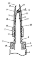
図1他に示される可動ノズル部材3は、下部に雌螺子11を設け上部内周に摺動部12を設けた筒体13の上端部に円錐形塗布ノズル14を有する。その可動ノズル部材3を固定中栓部材2に、液密に前後進摺動可能に被嵌し、円錐形塗布ノズル14の外形は円錐形をなし、且つ、容易にナイフなどで切断される0.2mmから5mmの肉厚で形成する。 A
中栓9は切断容易手段として図2他に示されるように環状溝15を複数設ける仕様、あるいは図7、図8に図示されるように切断容易手段としては中空部16を設けてもよい、チューブあるいはカートリッジの排出口4と固定中栓部材2は一体で形成されてもよい。The
図1は初期使用前のチューブ又はカートリッジ容器に装着された中栓付塗布ノズルを示している。次に図3から図6に基づいて説明をする。中栓9が栓として機能する目印手段の切断目印環状突部17より先端部寄りを中栓9及び円錐形塗布ノズル14を図3図5に一例を示す任意の形状に使用目的にあわせてナイフで直交切断あるいは傾斜切断開口する。この時に円錐形塗布ノズル14の先端部寄りを切断すると図5に図示される様に注出口開口部口径は細く、円錐形塗布ノズル14基部寄りでは図3に図示される様に太くなる。次に固定中栓部材回転防止凸部18を指で固定し可動ノズル部材3を螺動前進させ、厚肉部19が環状突部20に達して厚肉の為に拡張しづらくなり螺動前進が容易でなくなる時に螺動前進を停止させる。図4図6は上述の螺動前進を停止した図である。FIG. 1 shows a coating nozzle with an inner stopper attached to a tube or cartridge container before initial use. Next, a description will be given based on FIGS. The
次にコーキング材が充填されたチューブ又はカートリッジ容器を押圧することにより、容器排出口より排出されたコーキング材は、筒体5と通過穴8及び間隙部21を通過し注出口開口部22より注出される、この時に上述の螺動前進により厚肉部19は環状突部20を強く締め付けている状態であるために、間隙部21内の圧力が高まる押圧時に螺子部への逆流は阻止され、且つ可動ノズル部材3のぐら付きも防止される、次に直接工作物にあてがいコーキング材のコーキング作業を行う。 Next, when the tube or cartridge container filled with the caulking material is pressed, the caulking material discharged from the container discharge port passes through the
作業終了後可動ノズル部材3を螺動後進すると、間隙部21および中栓切断部23と注出口開口部22に残置されたコーキング材は押し出され同時に栓がされる。次回使用時は可動ノズル部材3を螺動前進することによりコーキング材のコーキング作業を再び行える。When reverse threadedly work after the end of the
可動ノズル部材3の栓を締め忘れ円錐形塗布ノズル内部でコーキング材が硬化したときに分解をするには、可動ノズル部材3の厚肉部19が環状突部20に達し螺動前進が容易でなくなるとき強制的にさらに螺動前進させて可動ノズル部材3を固定中栓部材2より分離させ円錐形塗布ノズル内部のコーキング材を除去する。 Forgetting to tighten the stopper of the
以上、本発明の実施の形態について説明したが、本発明は図示したもののみに限定されるものではなく、円錐形塗布ノズル外形は円錐形に限られず容易にナイフで切断できる肉厚で形成した多角錐形でも、また可動ノズル部材の前後進摺動は螺動に限られず直線的前後進摺動でも適用が可能であり、また注出物質はコーキング材に限らず接着剤でも適用が可能である。The embodiment of the present invention has been described above, but the present invention is not limited to the illustrated one, and the outer shape of the conical application nozzle is not limited to the conical shape, and is formed with a thickness that can be easily cut with a knife. Even in a polygonal pyramid shape, the sliding movement of the movable nozzle member is not limited to screwing, but can be applied to linear sliding movement, and the pouring material is not limited to caulking material but can be applied with adhesive. is there.
【図1】 本発明の中栓付塗布ノズルの注出部の切断前縦断面図
【図2】 固定中栓部材の正面図と平面図
【図3】 中栓付塗布ノズルの注出口開口部口径を太く切断後の断面図
【図4】 中栓付コーキング塗布ノズルの注出口開口部口径を太く切断後の使用状態断面図
【図5】 中栓付塗布ノズルの注出口開口部口径を細く切断後断面図
【図6】 中栓付塗布ノズルの注出口開口部口径を細く切断後の使用状態断面図
【図7】 中栓付塗布ノズルの注出口開口部を切断後の中栓中空仕様の断面図
【図8】 中栓付塗布ノズルの注出口開口部を切断後の使用状態の中栓中空仕様の図FIG. 1 is a longitudinal cross-sectional view of a dispensing nozzle with an inner stopper according to the present invention before cutting. FIG. 2 is a front view and a plan view of a fixed inner stopper member. Cross-sectional view after cutting the nozzle diameter [Fig. 4] Cross-sectional view of the operating state after cutting the outlet opening of the caulking coating nozzle with an inner plug thickly [Fig. 5] Thinner outlet opening diameter of the coating nozzle with an inner plug Cross-sectional view after cutting [Fig. 6] Cross-sectional view of the usage state after narrowing the diameter of the spout opening of the coating nozzle with an inner plug [Fig. 7] Hollow plug specification after cutting the spout opening of the coating nozzle with an inner plug Cross-sectional view of Fig. 8 Diagram of hollow plug hollow specification in use after cutting out spout opening of coating nozzle with plug
1…チューブ又はカートリッジ型容器 4…排出口
21…間隙部
固定中栓部
2…固定中栓部材 5…筒体
6…雄螺子 8…通過穴
9…中栓 10…円錐形部
15…環状溝 16…中空部
18…固定部材回転防止凸部 20…環状突部
23…中栓切断部 24…中栓支持柱
可動ノズル部
3…可動ノズル部材 11…雌螺子
12…摺動部 13…筒体
14…円錐形塗布ノズル 17…切断目印環状突部
19…厚肉部 22…注出口開口部DESCRIPTION OF
Claims (2)
Priority Applications (1)
| Application Number | Priority Date | Filing Date | Title |
|---|---|---|---|
| JP2007326525A JP4301459B2 (en) | 2007-11-19 | 2007-11-19 | Application nozzle with internal stopper |
Applications Claiming Priority (1)
| Application Number | Priority Date | Filing Date | Title |
|---|---|---|---|
| JP2007326525A JP4301459B2 (en) | 2007-11-19 | 2007-11-19 | Application nozzle with internal stopper |
Publications (2)
| Publication Number | Publication Date |
|---|---|
| JP2009125742A JP2009125742A (en) | 2009-06-11 |
| JP4301459B2 true JP4301459B2 (en) | 2009-07-22 |
Family
ID=40817196
Family Applications (1)
| Application Number | Title | Priority Date | Filing Date |
|---|---|---|---|
| JP2007326525A Expired - Fee Related JP4301459B2 (en) | 2007-11-19 | 2007-11-19 | Application nozzle with internal stopper |
Country Status (1)
| Country | Link |
|---|---|
| JP (1) | JP4301459B2 (en) |
Cited By (1)
| Publication number | Priority date | Publication date | Assignee | Title |
|---|---|---|---|---|
| JP2020183255A (en) * | 2019-05-07 | 2020-11-12 | 田中 初夫 | Coating nozzle with inner plug |
-
2007
- 2007-11-19 JP JP2007326525A patent/JP4301459B2/en not_active Expired - Fee Related
Cited By (1)
| Publication number | Priority date | Publication date | Assignee | Title |
|---|---|---|---|---|
| JP2020183255A (en) * | 2019-05-07 | 2020-11-12 | 田中 初夫 | Coating nozzle with inner plug |
Also Published As
| Publication number | Publication date |
|---|---|
| JP2009125742A (en) | 2009-06-11 |
Similar Documents
| Publication | Publication Date | Title |
|---|---|---|
| US5248071A (en) | Re-sealable nozzle and cap assembly | |
| US20020170926A1 (en) | Two-component cartridge system | |
| US8985402B2 (en) | Cove base nozzle for dispensing applications | |
| US10143535B2 (en) | Container for storing and dispensing a liquid | |
| US7032790B2 (en) | Container, sealing cap and method for sealing a nozzle tip of a curable liquid dispensing container | |
| JP2010069098A (en) | Storage container for dental adhesive | |
| US20090152307A1 (en) | Non-cylindrical bead for caulking tube | |
| JP4301459B2 (en) | Application nozzle with internal stopper | |
| JPH0741022A (en) | Container with nozzle cap | |
| US7014079B2 (en) | Caulking tube replacement tip | |
| US6398085B2 (en) | Cover systems and methods for elongate members | |
| JP2000177767A (en) | Application container | |
| US7275884B2 (en) | Fluid dispensing device | |
| JP5074072B2 (en) | Extrusion gun application nozzle, mounting aid and nozzle cap structure | |
| JP5041880B2 (en) | nozzle | |
| JPH0213110Y2 (en) | ||
| JP5046876B2 (en) | Liquid application container | |
| KR100527790B1 (en) | Bottle for adhesive | |
| JP3863160B2 (en) | Tile roof construction method and adhesive dispenser used therefor | |
| JPS601222B2 (en) | Cartridge extrusion tool | |
| JP2005289489A (en) | Container for discharging adhesive agent | |
| JP4626958B2 (en) | Viscous material dispensing container | |
| KR200354361Y1 (en) | Bottle for adhesive | |
| JPH09255055A (en) | Rigid container for viscous fluid | |
| JP3133368U (en) | Plastic container outlet |
Legal Events
| Date | Code | Title | Description |
|---|---|---|---|
| TRDD | Decision of grant or rejection written | ||
| A01 | Written decision to grant a patent or to grant a registration (utility model) |
Free format text: JAPANESE INTERMEDIATE CODE: A01 Effective date: 20090317 |
|
| A01 | Written decision to grant a patent or to grant a registration (utility model) |
Free format text: JAPANESE INTERMEDIATE CODE: A01 |
|
| FPAY | Renewal fee payment (event date is renewal date of database) |
Free format text: PAYMENT UNTIL: 20120501 |
|
| R150 | Certificate of patent or registration of utility model |
Ref document number: 4301459 Country of ref document: JP Free format text: JAPANESE INTERMEDIATE CODE: R150 Free format text: JAPANESE INTERMEDIATE CODE: R150 |
|
| FPAY | Renewal fee payment (event date is renewal date of database) |
Free format text: PAYMENT UNTIL: 20120501 Year of fee payment: 3 |
|
| FPAY | Renewal fee payment (event date is renewal date of database) |
Free format text: PAYMENT UNTIL: 20150501 Year of fee payment: 6 |
|
| R250 | Receipt of annual fees |
Free format text: JAPANESE INTERMEDIATE CODE: R250 |
|
| R250 | Receipt of annual fees |
Free format text: JAPANESE INTERMEDIATE CODE: R250 |
|
| R250 | Receipt of annual fees |
Free format text: JAPANESE INTERMEDIATE CODE: R250 |
|
| R250 | Receipt of annual fees |
Free format text: JAPANESE INTERMEDIATE CODE: R250 |
|
| LAPS | Cancellation because of no payment of annual fees |