JP2010069098A - Storage container for dental adhesive - Google Patents
Storage container for dental adhesive Download PDFInfo
- Publication number
- JP2010069098A JP2010069098A JP2008241422A JP2008241422A JP2010069098A JP 2010069098 A JP2010069098 A JP 2010069098A JP 2008241422 A JP2008241422 A JP 2008241422A JP 2008241422 A JP2008241422 A JP 2008241422A JP 2010069098 A JP2010069098 A JP 2010069098A
- Authority
- JP
- Japan
- Prior art keywords
- container
- dripping
- storage container
- adhesive
- discharge port
- Prior art date
- Legal status (The legal status is an assumption and is not a legal conclusion. Google has not performed a legal analysis and makes no representation as to the accuracy of the status listed.)
- Granted
Links
Images


Classifications
-
- A—HUMAN NECESSITIES
- A61—MEDICAL OR VETERINARY SCIENCE; HYGIENE
- A61C—DENTISTRY; APPARATUS OR METHODS FOR ORAL OR DENTAL HYGIENE
- A61C5/00—Filling or capping teeth
- A61C5/60—Devices specially adapted for pressing or mixing capping or filling materials, e.g. amalgam presses
- A61C5/62—Applicators, e.g. syringes or guns
Abstract
Description
本発明は、歯科医療において虫歯を治療する際などに用いる歯科用接着剤の保管容器に関する。 The present invention relates to a container for storing a dental adhesive used for treating dental caries in dentistry.
一般に虫歯と呼ばれている「う蝕」は、歯科医療における代表的な疾患であり、年齢や性別を問わず多くの人々が経験する。う蝕が進行した場合、自然治癒は困難であるため、歯科医師によって何らかの治療を行う必要がある。この治療に際しては、う蝕部分を歯科用研削材等で削除することにより窩洞を形成して、この窩洞内にコンポジットレジンなどの歯科用充填材を充填して、天然歯の解剖学的形態を再現する方法が広く普及している。なおコンポジットレジンは、その硬化方法の違いから化学重合型と光重合型に大別され、用途に応じて使い分けられている。 “Caries”, commonly called dental caries, is a typical disease in dentistry and is experienced by many people regardless of age or gender. When caries progresses, natural healing is difficult, and some treatment must be performed by a dentist. In this treatment, a cavity is formed by removing the carious portion with a dental abrasive or the like, and a dental filler such as a composite resin is filled in the cavity to form an anatomical form of the natural tooth. The method of reproduction is widespread. Composite resins are broadly classified into chemical polymerization type and photopolymerization type due to the difference in curing method, and are used properly according to the application.
コンポジットレジンは、単独では歯質と接着しないため、歯質とコンポジットレジンとの間に介在する歯科用接着剤が別途必要になるが、近年、歯科接着分野の技術革新が急速に進み、歯質だけではなく、金属、セラミックス、コンポジットレジン等の被着体に対しても強固に接着できるようになってきた。また従来、接着剤を使用する際は、エッチング、プライミング、ボンディング等の複数の工程が必要であり、工程毎にそれぞれの保管容器に収納された接着剤等の液材をディッシュ上の別々のウェルに滴下して、術式通り順番に適用部位に塗布していた。しかし、操作術式の簡略化と安定した接着力の発現等のユーザーからのニーズにより、エッチングとプライミングの工程が一つになったセルフエッチングプライマーや、エッチング・プライミング・ボンディングの工程が一つになったオールインワンアドヒーシブ等が開発され、操作性及び接着性の向上とともに、液材を収納する保管容器数も減少する傾向にある。ただし、全面的にオールインワンに置き換わった訳ではなく、二つの保管容器からそれぞれの液材をディッシュ上の同一のウェルに重なり合うように規定量を順番に滴下して、それらを混和することにより使用する2液混合タイプと呼ばれる接着剤も広く使用されている。 Since a composite resin alone does not adhere to the tooth, a separate dental adhesive is required between the tooth and the composite resin. In addition to this, it has become possible to adhere firmly to adherends such as metals, ceramics, and composite resins. Conventionally, when an adhesive is used, a plurality of processes such as etching, priming, and bonding are required, and liquid materials such as an adhesive stored in each storage container for each process are separated into separate wells on the dish. And applied to the application site in order according to the surgical procedure. However, due to user needs such as simplified operation techniques and stable adhesion, self-etching primer with a single etching and priming process and etching / priming / bonding process are combined into one. All-in-one adhesives and the like that have been developed have been developed, and there is a tendency that the number of storage containers for storing the liquid material is reduced along with improvement in operability and adhesiveness. However, it is not completely replaced with all-in-one, but it is used by dropping a prescribed amount in order so that each liquid material overlaps the same well on the dish from two storage containers and mixing them. An adhesive called a two-component mixed type is also widely used.
歯科用接着剤の一回当たりの塗布量は微量であるため、保管容器からの滴下量が多すぎると廃棄する量も増えてコスト高に繋がる。そのため微量の滴下量を確実に制御できるよう、容器の先端部に位置するノズルの吐出口形状やその口径のほか、ノズルに繋がる流路の長さと孔径などは厳密に管理されている。特に2液混合タイプの接着剤で設計通りの性能を発揮するには、それぞれの接着剤の滴下量及びそれらの混合割合が重要となるため、より厳密に管理されている。また接着剤の一回当たりの使用量は前記のように微量であり、しかも有効期限も存在するため、その保管容器は必然的に小形になり、底部からキャップまでの高さは最大でも5cm程度である。そのため接着剤をディッシュに滴下する際は、保管容器を下向きにして親指と人差し指でその側面を挟み込んで押圧するスタイルが一般的である。なお、この押圧の動作は、通常「スクイズ」と表現されている。 Since the application amount of the dental adhesive per one time is very small, if the amount dropped from the storage container is too large, the amount to be discarded increases and the cost increases. Therefore, in addition to the shape and diameter of the nozzle located at the tip of the container, the length and the diameter of the flow path connected to the nozzle are strictly controlled so that a small amount of dripping can be controlled with certainty. In particular, in order to exhibit the performance as designed with a two-component mixed adhesive, the dripping amount of each adhesive and the mixing ratio thereof are important, so that they are more strictly controlled. In addition, the amount of adhesive used per time is very small as described above, and the expiration date also exists, so the storage container is inevitably small, and the height from the bottom to the cap is about 5 cm at the maximum. It is. Therefore, when the adhesive is dropped onto the dish, a general style is that the storage container is faced down and the side surface is sandwiched between the thumb and forefinger and pressed. This pressing operation is usually expressed as “squeeze”.
前記のように、近年は接着剤の技術革新が進んでおり、接着剤組成にも変化が見られ、適用部位への濡れ性や浸透性を向上させるため、また塗布後の乾燥を確実に行うため、水や揮発溶媒が主成分となった低粘性の接着剤組成に移行しつつある。その結果、従来のような親指と人差し指で容器側面を押圧するといった滴下スタイルでは、接着剤の表面張力が低いため、保管容器を傾けた際に接着剤が勝手に流れ出て、ディッシュ以外のところに自然滴下することがあり、また保管容器を押圧する際、力加減の微妙な違いによって滴下量に許容範囲を超える誤差が生じることがある。このように従来の滴下スタイルは、接着剤組成が移行しつつある現状に対応しておらず、滴下動作や滴下量等といった面で安定性が不足しており、繊細な滴下作業には適していない。 As mentioned above, in recent years, technological innovations in adhesives have progressed, and changes have also been seen in the adhesive composition. In order to improve the wettability and permeability to the application site, it is also necessary to dry after application. Therefore, it is shifting to a low-viscosity adhesive composition mainly composed of water or a volatile solvent. As a result, in conventional dripping styles where the side of the container is pressed with the thumb and forefinger, the surface tension of the adhesive is low, so that when the storage container is tilted, the adhesive flows out freely, and it is not in the dish. When the storage container is pressed naturally, an error exceeding the allowable range may occur in the dropping amount due to a slight difference in force. As described above, the conventional drip style does not correspond to the current situation in which the adhesive composition is shifting, lacks stability in terms of drip operation, drip amount, etc., and is suitable for delicate drip work. Absent.
またスクイズの際、保管容器の姿勢は歯科医師の好みによって異なり、例えばノズルをほぼ真下に向ける場合のほか、ノズルをほぼ水平に向ける場合もある。このような姿勢の変化によって、容器内の液面と吐出口との位置関係なども変化するため、滴下量にもばらつきが生じて、必要以上に接着剤を滴下する場合があるほか、2液混合タイプの場合、正確な混合割合が維持できないといった課題もある。 Further, when squeezing, the posture of the storage container varies depending on the preference of the dentist. For example, in addition to directing the nozzle almost directly below, the nozzle may be oriented almost horizontally. Due to such a change in posture, the positional relationship between the liquid level in the container and the discharge port also changes, so that the amount of dripping also varies, and the adhesive may be dripped more than necessary. In the case of the mixed type, there is a problem that an accurate mixing ratio cannot be maintained.
さらに歯科用接着剤は品質を維持するため、冷蔵庫内で保管する必要があるが、使用に先立って常温環境下に放置して、接着剤が常温に戻った後、実際に使用される。このように冷蔵庫から取り出した保管容器を扱う際は、指からの体温が保管容器を経て接着剤に伝達するため、接着剤中に含まれる揮発溶媒が膨張して、キャップを外した際、接着剤がノズル先端部から吹き出たり、滴下する際、ノズル先端部から接着剤が連続的に滴下したりといった、使用者の意に反する現象が起こることがある。このような滴下動作過程において、指からの熱伝達による温度上昇を抑制するため、下記特許文献のような技術が開発されている。この技術は、容器を二重構造にするもので、外容器と内容器の間に空気層が形成され、指からの熱伝達を抑制できるため、温度変化による保管容器中に収納された接着剤の膨張が抑制される。
本発明はこうした実情を基に開発されたもので、歯科用接着剤の使用時において安定な滴下動作と、滴下量の厳密化等の微細な滴下作業を再現性よく円滑に実施でき、しかも内部に収納されている接着剤の温度上昇による膨張も抑制可能な、歯科用接着剤の保管容器の提供を目的としている。 The present invention was developed on the basis of such a situation, and when using a dental adhesive, a stable dropping operation and a fine dropping operation such as strict dropping amount can be performed smoothly with good reproducibility. It is an object of the present invention to provide a dental adhesive storage container capable of suppressing expansion due to a temperature rise of the adhesive contained in the dental adhesive.
前記の課題を解決するための請求項1記載の発明は、細長状で内部に液体を収容可能な容器部を備え、該容器部の一端面側には外部と連通する吐出口を有しており、前記容器部の他端面側は底壁によって塞がれており、該底壁から吐出口の反対側に向けて突出する尾部が形成してあることを特徴とする歯科用接着剤の保管容器である。 The invention according to claim 1 for solving the above-mentioned problem has an elongated container portion that can accommodate a liquid therein, and has a discharge port that communicates with the outside on one end surface side of the container portion. And the other end surface of the container is closed by a bottom wall, and a tail protruding from the bottom wall toward the opposite side of the discharge port is formed. It is a container.
本発明による保管容器は、歯科医師等に歯科用接着剤を供給するためのもので、製造段階などで使用するものではない。そして保管容器の構成要素である容器部は、エッチング、プライミング、ボンディング等、一連の接着工程で使用する各種液体を収容する空洞状の部位であり、細長い筒状で密閉性が確保されていることを前提とするが、断面形状については自在であり、円形のほか正方形や六角形などでもよい。また吐出口は、容器部に収容された液体を外部に排出する機能を有しており、容器部の一端面側に配置される。なお吐出口は、必ずしも容器部と一体的に形成する必要はなく、別途に吐出口を備えた口栓を用いて、容器部に組み込んでもよい。いずれの場合も吐出口を塞ぐため、着脱自在なキャップが別途必要になる。 The storage container according to the present invention is for supplying a dental adhesive to a dentist or the like, and is not used at the manufacturing stage. The container part, which is a component of the storage container, is a hollow part that contains various liquids used in a series of bonding processes such as etching, priming, bonding, etc. However, the cross-sectional shape is arbitrary, and it may be a circle or a square or a hexagon. The discharge port has a function of discharging the liquid contained in the container part to the outside, and is disposed on one end surface side of the container part. The discharge port does not necessarily have to be formed integrally with the container part, and may be incorporated into the container part using a stopper having a separate discharge port. In either case, a detachable cap is required to close the discharge port.
このように容器部の一端面側には吐出口を備えているが、その反対面には、容器部の内部を密閉するための底壁を備えている。そして本発明では、この底壁を基点として、吐出口とは反対側に突出する尾部が形成されていることを特徴とする。この尾部は、容器部と一体的に形成してもよいが、別途に製作して接合することもできる。また尾部は、容器部との境界に段差などがない一体的な形状とすることが好ましく、さらに美感などを考慮して端部を先細りとしてもよい。ただし尾部は、あくまでも容器部の底壁から突出するものであり、その内部に液体を収容することはできない。このような尾部を形成することで、内容量を増大させることなく保管容器の全長を増大させることができ、使用の際、鉛筆などの筆記具と同様、親指と人差し指のほか、中指の側面や人差し指の付け根部分でも容器を支持できるようになり、安定性が向上する。なお本発明は、容器部、吐出口、尾部のいずれも樹脂を素材とすることを前提とするが、具体的な材質については限定しない。 As described above, the discharge port is provided on the one end surface side of the container part, and the bottom wall for sealing the inside of the container part is provided on the opposite surface. The present invention is characterized in that a tail portion protruding from the bottom wall on the side opposite to the discharge port is formed. The tail portion may be formed integrally with the container portion, but may be separately manufactured and joined. The tail portion preferably has an integral shape with no step at the boundary with the container portion, and the end portion may be tapered in consideration of aesthetics. However, the tail part protrudes from the bottom wall of the container part to the last, and liquid cannot be accommodated in the inside. By forming such a tail, it is possible to increase the total length of the storage container without increasing the internal volume, and in use, as with a writing instrument such as a pencil, in addition to the thumb and index finger, the side of the middle finger and the index finger It becomes possible to support the container even at the base part of, and stability is improved. In addition, although this invention presupposes that all of a container part, a discharge outlet, and a tail part are made from resin, it does not limit about a specific material.
請求項2記載の発明は、保管容器の形状を限定するもので、吐出口から尾部の端面までの長さは、8cm以上且つ15cm以下であることを特徴とする。この寸法は、キャップを外した状態において、吐出口の先端から尾部の後端面までの直線距離を意味している。このように長さを限定することで、吐出口付近を親指と人差し指で挟み込んだ際、尾部が人差し指の付け根付近に接触するため安定性が向上して、しかも過度に長くもなく、取り扱いが容易で操作性に優れている。なお長さが8cmより小さいと、尾部が人差し指の付け根付近に接触できない場合があり、本発明による利便性が発揮できない。 The invention according to claim 2 limits the shape of the storage container, and the length from the discharge port to the end surface of the tail is 8 cm or more and 15 cm or less. This dimension means a linear distance from the front end of the discharge port to the rear end surface of the tail in a state where the cap is removed. By limiting the length in this way, when the vicinity of the discharge port is sandwiched between the thumb and forefinger, the tail contacts the vicinity of the base of the index finger, so stability is improved and it is not excessively long and easy to handle. Excellent operability. If the length is smaller than 8 cm, the tail portion may not be able to contact the vicinity of the base of the index finger, and the convenience according to the present invention cannot be exhibited.
請求項3記載の発明は、容器部の外周を取り囲む外容器を備え、且つ前記尾部は、該外容器の長手方向に延在するように形成してあることを特徴とする。外容器は、容器部の外側を取り囲むもので、しかも本発明では外容器を長手方向に延長することで、前記の尾部としての機能を兼ね備えていることを特徴としている。したがって本発明による外容器は、容器部よりも長く、且つ底壁よりも後方に突出した形状になる。なお外容器は、容器部に収容された液体の温度変化を緩和する断熱材としても機能するが、必ずしも容器部と外容器の間に空気層を確保する必要はなく、双方が全面的に接触していても構わない。ただし外容器を押圧することで容器部も変形して、内部の液体を確実に滴下できるものとする。 According to a third aspect of the present invention, an outer container surrounding the outer periphery of the container part is provided, and the tail part is formed to extend in the longitudinal direction of the outer container. The outer container surrounds the outer side of the container part, and in the present invention, the outer container is extended in the longitudinal direction so as to function as the tail part. Therefore, the outer container according to the present invention is longer than the container part and has a shape protruding rearward from the bottom wall. The outer container also functions as a heat insulating material that alleviates the temperature change of the liquid contained in the container part, but it is not always necessary to secure an air layer between the container part and the outer container. It does not matter. However, the container part is also deformed by pressing the outer container, and the liquid inside can be reliably dropped.
請求項4記載の発明は、外容器の形状を限定するもので、外容器の側面には、長手方向に沿ってスリットが形成してあることを特徴とする。スリットは、外容器の側面を長手方向に沿って切り裂いたもので、スリットが一列の場合、横断面がC字状になる。したがって外容器の側面を押圧した場合、その内径が縮まるように変形しやすくなり、内接する容器部を容易に押圧でき、液体の吐出を円滑に行うことができる。特に、断熱性やグリップ感の向上を目的として外容器の厚さを増大させた場合、必然的に外容器の剛性も大きくなるのでスリットの効果が顕著になる。
The invention described in
このスリットの形成方向は、原則として保管容器の長手方向だが、若干の傾きがあっても構わない。またスリットは、外容器の両端面を結ぶように形成して、全域をC字断面とする場合のほか、容器部と重なる区間だけに形成して、残りの区間はスリットのない環状にすることもできる。このようにスリットを区間限定とする場合、スリットを二列以上形成できるようになり、柔軟性が一段と向上する。 The slit is formed in principle in the longitudinal direction of the storage container, but may be slightly inclined. In addition to forming the slits so as to connect both end faces of the outer container and making the entire area a C-shaped cross section, the slit is formed only in the section overlapping the container part, and the remaining section is formed in an annular shape without a slit. You can also. In this way, when the slits are limited to sections, it becomes possible to form two or more rows of slits, and the flexibility is further improved.
請求項1記載の発明のように、接着剤等の液体を収容する容器部に加えて、吐出口の反対側に突出する尾部を設けることで、使用の際、吐出口付近を親指と人差し指で支持でき、しかも人差し指の付け根付近で保管容器の尾部を支持できるため、鉛筆などの筆記具を持つ際のような三点以上で本発明品を保持でき、滴下操作時における保持状態及び安定性に優れる。その結果、滴下時におけるスクイズも安定することから、必要最小限の液体を正確に、且つ迅速に滴下することが可能となり、処置を終えた際、ディッシュに残留する量も最小限に留めることができ、コストの抑制も実現する。 As in the first aspect of the present invention, in addition to the container portion for storing the liquid such as the adhesive, a tail portion protruding to the opposite side of the discharge port is provided, so that the vicinity of the discharge port can be used with the thumb and forefinger in use. Since it can support and can support the tail of the storage container near the base of the index finger, it can hold the product of the present invention at three or more points as when holding a writing instrument such as a pencil, and is excellent in the holding state and stability during the dropping operation . As a result, the squeeze at the time of dripping is also stable, so it becomes possible to dripping the necessary minimum liquid accurately and quickly, and the amount remaining in the dish can be kept to a minimum when the treatment is completed. And cost reduction.
また従来の保管容器では、歯科医師の好みによって使用時の姿勢が異なり、これによる滴下量の違いが生じていたが、本発明では、必然的に筆記具のような持ち方に固定され、常に姿勢が安定して滴下量も一定になる。しかも筆記具を扱う際のような自然な姿勢で操作を遂行できるため、円滑で迅速な滴下動作が実現して、熱伝導による内部の液体の温度上昇も抑制できる。さらに、2液混合タイプの接着剤の場合、本来の接着性能を発揮させるには、精度の高い厳密な滴下量が要求されるが、本発明では、前記のように筆記具を扱う際と同様の感覚で迅速且つ円滑に滴下が可能で、滴下する液体毎の混合割合も正確に管理でき、所定の接着性能を発揮できると共に作業時間も短縮できる。なお本発明による尾部は、接着剤を収容する機能を有しておらず内容量は従来と変わりがなく、消費期限の管理は従来と何ら変わりがない。 Also, with conventional storage containers, the posture during use differs depending on the preference of the dentist, and this caused a difference in the amount of dripping, but in the present invention, it is necessarily fixed in a holding manner like a writing instrument, and always posture However, the dripping amount becomes constant. Moreover, since the operation can be performed with a natural posture like when handling a writing instrument, a smooth and quick dropping operation can be realized, and the temperature rise of the internal liquid due to heat conduction can be suppressed. Further, in the case of a two-component mixed type adhesive, in order to exhibit the original adhesive performance, a precise and precise dripping amount is required, but in the present invention, it is the same as when handling a writing instrument as described above. Dropping can be performed quickly and smoothly with a sense, and the mixing ratio of each dropped liquid can be accurately managed, and a predetermined bonding performance can be exhibited and work time can be shortened. The tail portion according to the present invention does not have a function of accommodating the adhesive, and the internal capacity is the same as the conventional one, and the management of the expiration date is no different from the conventional one.
請求項2記載の発明のように、保管容器の全長を限定することで、使用の際、親指と人差し指で保管容器の吐出口の近傍を挟み込むと、必然的に保管容器の尾部が人差し指の付け根付近に接触して、確実に請求項1記載の発明の効果を発揮でき、しかも過度に長くもないため、操作性が悪化することもなく、さらに保管場所などに困ることもない。 By limiting the overall length of the storage container as in the second aspect of the invention, in use, when the vicinity of the discharge outlet of the storage container is sandwiched between the thumb and forefinger, the tail of the storage container is inevitably placed at the base of the index finger. Since the effect of the invention of claim 1 can be surely exerted by coming into contact with the vicinity, and it is not excessively long, the operability is not deteriorated and the storage location is not troubled.
請求項3記載の発明のように、液体を収容する容器部とは別に外容器を設けて、この外容器の一端を突出させて尾部を形成することで、請求項1記載の発明のような筆記具と同様の操作性が実現するほか、容器部と外容器との二重構造になるため断熱性が向上して、揮発性の高い液体でも急激な膨張を防止でき、思わぬ状況で液体が滴下することもない。また請求項4記載の発明のように、外容器にスリットを設けることで、外容器の剛性が低下するため、外容器を軽く押圧するだけで規定量の液体を滴下できる。
As in the invention described in claim 3, the outer container is provided separately from the container portion that stores the liquid, and one end of the outer container is protruded to form the tail portion. In addition to realizing the same operability as a writing instrument, it has a double structure with a container and an outer container, improving heat insulation and preventing rapid expansion even with highly volatile liquids. There is no dripping. Moreover, since the rigidity of an outer container falls by providing a slit in an outer container like invention of
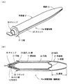
図1は、本発明による保管容器10aの形状例を示しており、図1(A)は外観で、図1(B)は中央部の縦断面である。このように本発明による保管容器10aは、ほぼ円断面の棒状であり、その内部には、エッチング、プライミング、ボンディング等、一連の接着工程で使用する各種液体を収容するための容器部11を備え、また図の左側の端面には液体を滴下するための吐出口12を備えている。さらに容器部11の側周面は外容器21によって覆われており、この外容器21の右側の端部は先細りの円錐形になっている。なお吐出口12は、容器部11とは別途に製造された口栓31の先端に形成されており、この口栓31にキャップ36を螺合することで内部を密閉する構造になっている。したがって口栓31の外周およびキャップ36の内周にはネジ部34が形成されている。また容器部11および外容器21は、比較的軟質なポリプロピレン樹脂を素材としており、口栓31およびキャップ36は、密閉性を確保するため、より硬質のポリエチレンテレフタレート樹脂を素材としている。
FIG. 1 shows an example of the shape of a
容器部11は単純な円筒状だが、内部に液体を収容するため密閉性が不可欠であり、その左側の端部は口栓31の中に圧入されており、また右側の端部は、一体で成形された底壁14によって塞がれている。対する外容器21は密閉性が不要であり、側周面には長手方向に延在するスリット25が形成され、しかも右側の端面は塞がっておらず円形に開放している。そのため外容器21は、全域でスリット25の入ったC字状の横断面になり、側周面を指などで押圧すると、スリット25の間隔が縮まるように弾性変形する。また外容器21の内周面には、長手方向に延在する凸条22が形成されており、この頂部が容器部11の側周面に接触している。したがって外容器21を押圧すると容器部11も押し潰されて、内部の液体を吐出口12から滴下できる。
The
図1(B)に示すように、外容器21は、容器部11の底壁14よりも大きく右側に突出している。このように、液体を収容する容器部11の底壁14よりも後方に突出している箇所を、本発明において尾部13と規定している。尾部13は液体を収容する機能は一切なく、あくまでも持ちやすさを向上するための部分である。また外容器21の左側の端面は、口栓31に形成されたフランジ32に接触しており、しかも口栓31と離脱不能に一体化している。そのほか、外容器21内周面の凸条22の右端には後爪24が形成され、容器部11を口栓31に押圧している。
As shown in FIG. 1B, the
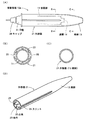
図2は、図1に示す保管容器10aの詳細を示しており、図2(A)は側面で、図2(B)は図2(A)のB−B端面で、図2(C)は図2(A)のC−C端面で、図2(D)は構成要素を分離した状態の縦断面である。図2(A)のように、本発明による保管容器10aは、鉛筆などに似た細長い形状になっており、容器部11を取り囲んでいる外容器21には、長手方向に延在する一列のスリット25が形成されている。また図2(B)および図2(C)の端面図のように、外容器21はC字状の断面になっているほか、計六列の凸条22が形成されており、この凸条22を介して外容器21と容器部11が接触しており、それ以外の場所では空気層が構成され、断熱性を確保している。
2 shows details of the
さらに図2(D)のように、口栓31とキャップ36は、双方に形成されたネジ部34によって着脱可能な構造になっている。また口栓31と外容器21は、口栓31の外周面に形成された溝33と、外容器21の内周面に形成された前爪23が噛み合うことで一体化している。そのほか、外容器21の内周面の凸条22の右端には、容器部11の底壁14周辺を拘束するため、中心方向に突出した後爪24が形成されている。
Further, as shown in FIG. 2D, the
図3は、図1とは異なる構造の保管容器10bを示しており、図3(A)は側面で、図3(B)は図3(A)のB−B端面で、図3(C)は図3(A)のC−C端面で、図3(D)は縦断面である。この構造も、容器部11や口栓31やキャップ36は図1と同様だが、外容器21は、スリット25を備えるものの、内周面には凸条22が形成されておらず、スリット25を除く外容器21の内周面全体が容器部11と接触している。そのため外容器21の形状を簡素化できるほか、外容器21の厚さを十分に確保することで、断熱性も発揮できる。なお本図に示す外容器21の尾部13は、図1(B)に示す形状と比べて短いが、容器部11の底壁14よりも図の右側に突出している点は同じである。このように外容器21の具体的な形状については、寸法や材質などに基づいて自在に決めることができる。
3 shows a storage container 10b having a structure different from that of FIG. 1, FIG. 3 (A) is a side view, FIG. 3 (B) is a BB end face of FIG. 3 (A), and FIG. ) Is a CC end surface of FIG. 3A, and FIG. 3D is a longitudinal section. In this structure, the
図4は、図1などとは異なり、容器部11と尾部13を一体で形成した保管容器10c、10dの縦断面を示しており、図4(A)は尾部13が中空で、図4(B)は尾部13が中実である。本発明は尾部13が形成されていれば、必ずしも外容器21は不要である。したがって液体を収容する容器部11に尾部13を一体的に形成して、構造を簡素化することもできる。このような一体構造の場合、尾部13は、底壁14よりも後寄りの液体が収容できない区間を示すが、単に容器部11の底壁14をやや厚くしただけの形態は、尾部13ではないものとする。また本図では、図1のような口栓31に相当する部品がなく、容器部11の左端に吐出口12を形成している。このように、吐出口12周辺の形状は何らの制限もなく、自在に決めることができる。
FIG. 4 shows a longitudinal section of storage containers 10c and 10d in which the
図5は、さらに別形態の保管容器10eの形状例を示しており、図5(A)は側面で、図5(B)は図5(A)のB−B端面で、図5(C)は図5(A)のC−C端面で、図5(D)は外容器21単体の形状である。この構造も、容器部11と口栓31とキャップ36については図1と全く同じである。また外容器21は、内周面に計六列の凸条22が形成されている点は同じだが、スリット25については、対向するように二列形成されており、外容器21の変形性が向上して容器部11の押圧が一段と確実になる。なおスリット25を二列以上形成しているため、外容器21が分割されないよう、その形成範囲を限定している。
FIG. 5 shows still another example of the shape of the storage container 10e. FIG. 5 (A) is a side view, FIG. 5 (B) is a BB end face of FIG. 5 (A), and FIG. ) Is a CC end face of FIG. 5A, and FIG. 5D is the shape of the
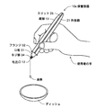
図6は、本発明による保管容器10aの使用状態を示している。このように本発明による保管容器10aは、尾部13を組み合わせることで鉛筆などに似た外観となる。そのため本図のように、鉛筆などを握る際と同様、親指と人差し指で保管容器10aの先端部を挟み込んだ上、中指で側周面を拘束しており、さらに人差し指の付け根付近で尾部13を支持でき、グリップ感に優れ意のままに取り扱うことができる。しかも本発明による保管容器10aは、液体滴下時における保持状態とその滴下角度等の安定性にも優れ、また滴下のスクイズ動作も安定することから規定量を厳密且つ迅速に滴下でき、さらに保管容器10a内部に収納されている液体への熱伝導による温度上昇も抑制することができる。
FIG. 6 shows a use state of the
10a、10b、10c、10d、10e (歯科用接着剤の)保管容器
11 容器部
12 吐出口
13 尾部
14 底壁
21 外容器
22 凸条
23 前爪
24 後爪
25 スリット
31 口栓
32 フランジ
33 溝
34 ネジ部
36 キャップ
10a, 10b, 10c, 10d, 10e Storage container 11 (for dental adhesive)
Claims (4)
Priority Applications (3)
| Application Number | Priority Date | Filing Date | Title |
|---|---|---|---|
| JP2008241422A JP5318509B2 (en) | 2008-09-19 | 2008-09-19 | Dental adhesive storage container |
| US12/550,408 US8662350B2 (en) | 2008-09-19 | 2009-08-31 | Storage container for dental adhesive |
| DE102009039624.1A DE102009039624B4 (en) | 2008-09-19 | 2009-09-01 | storage container for dental adhesive |
Applications Claiming Priority (1)
| Application Number | Priority Date | Filing Date | Title |
|---|---|---|---|
| JP2008241422A JP5318509B2 (en) | 2008-09-19 | 2008-09-19 | Dental adhesive storage container |
Publications (2)
| Publication Number | Publication Date |
|---|---|
| JP2010069098A true JP2010069098A (en) | 2010-04-02 |
| JP5318509B2 JP5318509B2 (en) | 2013-10-16 |
Family
ID=41694039
Family Applications (1)
| Application Number | Title | Priority Date | Filing Date |
|---|---|---|---|
| JP2008241422A Active JP5318509B2 (en) | 2008-09-19 | 2008-09-19 | Dental adhesive storage container |
Country Status (3)
| Country | Link |
|---|---|
| US (1) | US8662350B2 (en) |
| JP (1) | JP5318509B2 (en) |
| DE (1) | DE102009039624B4 (en) |
Cited By (1)
| Publication number | Priority date | Publication date | Assignee | Title |
|---|---|---|---|---|
| JP2012066875A (en) * | 2010-08-21 | 2012-04-05 | Gc Corp | Dripping container |
Families Citing this family (9)
| Publication number | Priority date | Publication date | Assignee | Title |
|---|---|---|---|---|
| DE202012013332U1 (en) * | 2011-11-02 | 2016-06-01 | Anke Elisabeth Viering | Set with dosing device for hand-controlled dosing of a light-curing material |
| JP2014231375A (en) * | 2013-05-29 | 2014-12-11 | 株式会社ジーシー | Container cover and dripping container |
| US20150079538A1 (en) * | 2013-07-26 | 2015-03-19 | Nathan Y. LI | Dental root canal filling material cartridge having built-in heating mechanism for softening the material |
| WO2015087737A1 (en) * | 2013-12-10 | 2015-06-18 | 横浜ゴム株式会社 | Puncture repair liquid-holding container |
| CN106029044B (en) | 2014-02-18 | 2019-12-31 | 3M创新有限公司 | Adhesive bonding composition and use thereof |
| JPWO2015133418A1 (en) * | 2014-03-04 | 2017-04-06 | 株式会社トクヤマデンタル | Plastic container for dental adhesive composition |
| US20170128158A1 (en) * | 2014-11-12 | 2017-05-11 | Dxm Co., Ltd | Dental material heating infuser for heating dental material by peltier element |
| JP6967583B2 (en) * | 2016-09-11 | 2021-11-17 | タルサ デンタル プロダクツ エルエルシー | A system for providing endodontic materials using induction heating |
| US20190380870A1 (en) * | 2018-06-14 | 2019-12-19 | Chromologic Llc | Ocular graft and applicator |
Citations (8)
| Publication number | Priority date | Publication date | Assignee | Title |
|---|---|---|---|---|
| JPH02143916U (en) * | 1989-05-09 | 1990-12-06 | ||
| JPH0360247U (en) * | 1989-10-11 | 1991-06-13 | ||
| JPH047443U (en) * | 1990-04-28 | 1992-01-23 | ||
| JPH0644779U (en) * | 1992-11-26 | 1994-06-14 | シヤチハタ工業株式会社 | Liquid application container |
| JPH07257644A (en) * | 1994-01-13 | 1995-10-09 | Thera Patent Gmbh & Co Kg G Fur Ind Schutzrechte | Device to make film pipe empty |
| JPH08215214A (en) * | 1994-11-30 | 1996-08-27 | Ernst Muehlbauer Kg | Compound applicator for dentistry |
| JP2002513665A (en) * | 1998-05-04 | 2002-05-14 | デンツプライ インターナショナル インコーポレーテッド | Dental adhesive container infusion system |
| JP3572158B2 (en) * | 1996-12-18 | 2004-09-29 | 株式会社トクヤマ | Liquid dripping equipment |
Family Cites Families (8)
| Publication number | Priority date | Publication date | Assignee | Title |
|---|---|---|---|---|
| US3643837A (en) * | 1969-08-25 | 1972-02-22 | Ronald A Green | Combination container-dispenser for viscous materials |
| US4421251A (en) * | 1981-10-01 | 1983-12-20 | Bahram Namdari | Motorized apparatus for dispensing cake icing |
| US4811866A (en) | 1987-01-02 | 1989-03-14 | Helena Laboratories Corporation | Method and apparatus for dispensing liquids |
| US5529217A (en) * | 1989-11-09 | 1996-06-25 | Siegel; Gerald | Squeeze bottle with insulating jacket |
| US5833119A (en) * | 1996-08-28 | 1998-11-10 | Liblan & Co., Inc. | Container for paste and gels |
| US6709180B2 (en) | 2002-08-21 | 2004-03-23 | Katherine J. Cochran | Ergonomic wax pen |
| JP2006515212A (en) | 2003-01-17 | 2006-05-25 | デンツプライ インターナショナル インコーポレーテッド | Pen-type liquid dispensing device |
| US7766190B2 (en) * | 2007-06-29 | 2010-08-03 | Fang-Pin Chen | Sealed crimp tube with stiffener |
-
2008
- 2008-09-19 JP JP2008241422A patent/JP5318509B2/en active Active
-
2009
- 2009-08-31 US US12/550,408 patent/US8662350B2/en active Active
- 2009-09-01 DE DE102009039624.1A patent/DE102009039624B4/en active Active
Patent Citations (8)
| Publication number | Priority date | Publication date | Assignee | Title |
|---|---|---|---|---|
| JPH02143916U (en) * | 1989-05-09 | 1990-12-06 | ||
| JPH0360247U (en) * | 1989-10-11 | 1991-06-13 | ||
| JPH047443U (en) * | 1990-04-28 | 1992-01-23 | ||
| JPH0644779U (en) * | 1992-11-26 | 1994-06-14 | シヤチハタ工業株式会社 | Liquid application container |
| JPH07257644A (en) * | 1994-01-13 | 1995-10-09 | Thera Patent Gmbh & Co Kg G Fur Ind Schutzrechte | Device to make film pipe empty |
| JPH08215214A (en) * | 1994-11-30 | 1996-08-27 | Ernst Muehlbauer Kg | Compound applicator for dentistry |
| JP3572158B2 (en) * | 1996-12-18 | 2004-09-29 | 株式会社トクヤマ | Liquid dripping equipment |
| JP2002513665A (en) * | 1998-05-04 | 2002-05-14 | デンツプライ インターナショナル インコーポレーテッド | Dental adhesive container infusion system |
Cited By (1)
| Publication number | Priority date | Publication date | Assignee | Title |
|---|---|---|---|---|
| JP2012066875A (en) * | 2010-08-21 | 2012-04-05 | Gc Corp | Dripping container |
Also Published As
| Publication number | Publication date |
|---|---|
| DE102009039624A9 (en) | 2010-07-15 |
| DE102009039624A1 (en) | 2010-03-25 |
| US8662350B2 (en) | 2014-03-04 |
| JP5318509B2 (en) | 2013-10-16 |
| DE102009039624B4 (en) | 2023-03-30 |
| US20100075276A1 (en) | 2010-03-25 |
Similar Documents
| Publication | Publication Date | Title |
|---|---|---|
| JP5318509B2 (en) | Dental adhesive storage container | |
| US9339359B2 (en) | Applicator instrument for dental compounds | |
| US6592280B2 (en) | Container and applicator assembly | |
| US5358349A (en) | Glue applicator | |
| US6543612B2 (en) | Container for compositions made of two or more components | |
| JP4283476B2 (en) | Package applicator assembly | |
| US20130324948A1 (en) | Cotton balls, cotton swabs and cotton swab holder | |
| US20100221678A1 (en) | Method for Indicating Shelf-Life After Mixing Pre-Dosed, Pre-Packaged Two-Part Dental Compositions | |
| US8267609B2 (en) | Vial for delivering contents onto a substrate | |
| KR200388881Y1 (en) | Spuit type lip-gloss case | |
| US6419414B1 (en) | Container for multiple-component compositions | |
| US7112062B2 (en) | Dental material storage and delivery system and method | |
| US20210153637A1 (en) | Clinical dispenser and applicator | |
| US11628986B2 (en) | Device for discharging a pourable substance | |
| US20150209191A1 (en) | Nose bleed kit | |
| JP2007276879A (en) | Compound container for adhesive | |
| US20140106298A1 (en) | Clinical Dispenser and Applicator | |
| JP2013240895A (en) | Applicator | |
| JP7408383B2 (en) | Chemical solution supply equipment and drug solution supply equipment | |
| JP2018090263A (en) | Liquid applying vessel | |
| WO2013111727A1 (en) | Tube container, and product containing tube container | |
| JP2005066052A (en) | Applicator | |
| EP2621395B1 (en) | Mixing tip for dental materials | |
| JP2019136347A (en) | Puncture needle cartridge and its manufacturing method | |
| JPH09150856A (en) | Nozzle structure in single push squeezing liquid container |
Legal Events
| Date | Code | Title | Description |
|---|---|---|---|
| A621 | Written request for application examination |
Free format text: JAPANESE INTERMEDIATE CODE: A621 Effective date: 20110114 |
|
| A977 | Report on retrieval |
Free format text: JAPANESE INTERMEDIATE CODE: A971007 Effective date: 20121025 |
|
| A131 | Notification of reasons for refusal |
Free format text: JAPANESE INTERMEDIATE CODE: A131 Effective date: 20121030 |
|
| A521 | Request for written amendment filed |
Free format text: JAPANESE INTERMEDIATE CODE: A523 Effective date: 20121218 |
|
| TRDD | Decision of grant or rejection written | ||
| A01 | Written decision to grant a patent or to grant a registration (utility model) |
Free format text: JAPANESE INTERMEDIATE CODE: A01 Effective date: 20130604 |
|
| A61 | First payment of annual fees (during grant procedure) |
Free format text: JAPANESE INTERMEDIATE CODE: A61 Effective date: 20130710 |
|
| R150 | Certificate of patent or registration of utility model |
Ref document number: 5318509 Country of ref document: JP Free format text: JAPANESE INTERMEDIATE CODE: R150 Free format text: JAPANESE INTERMEDIATE CODE: R150 |
|
| R250 | Receipt of annual fees |
Free format text: JAPANESE INTERMEDIATE CODE: R250 |
|
| R250 | Receipt of annual fees |
Free format text: JAPANESE INTERMEDIATE CODE: R250 |
|
| R250 | Receipt of annual fees |
Free format text: JAPANESE INTERMEDIATE CODE: R250 |
|
| R250 | Receipt of annual fees |
Free format text: JAPANESE INTERMEDIATE CODE: R250 |
|
| R250 | Receipt of annual fees |
Free format text: JAPANESE INTERMEDIATE CODE: R250 |
|
| R250 | Receipt of annual fees |
Free format text: JAPANESE INTERMEDIATE CODE: R250 |
|
| R250 | Receipt of annual fees |
Free format text: JAPANESE INTERMEDIATE CODE: R250 |
|
| R250 | Receipt of annual fees |
Free format text: JAPANESE INTERMEDIATE CODE: R250 |