JP4300937B2 - Car side impact response structure - Google Patents
Car side impact response structure Download PDFInfo
- Publication number
- JP4300937B2 JP4300937B2 JP2003300732A JP2003300732A JP4300937B2 JP 4300937 B2 JP4300937 B2 JP 4300937B2 JP 2003300732 A JP2003300732 A JP 2003300732A JP 2003300732 A JP2003300732 A JP 2003300732A JP 4300937 B2 JP4300937 B2 JP 4300937B2
- Authority
- JP
- Japan
- Prior art keywords
- seat
- vehicle
- reinforcing member
- width direction
- load
- Prior art date
- Legal status (The legal status is an assumption and is not a legal conclusion. Google has not performed a legal analysis and makes no representation as to the accuracy of the status listed.)
- Expired - Fee Related
Links
Images


Description
本発明は、自動車の側突対応構造に関するものである。 The present invention relates to a structure for dealing with a side collision of an automobile.
自動車の側突対応構造としては、下記特許文献1が知られている。
The following
同文献1に記載の自動車の側突対応構造は、フロアパネル上に取り付けられた左右のシート内にクロスメンバが車幅方向に配設され、左右のシート間のフロアパネルの凹部内のクロスメンバよりも低い位置に荷重伝達部材が配置され、さらに、凹部内に、衝突時に該荷重伝達部材を上方へと展開して左右シートのクロスメンバ間に配置させる跳ね上げ機構が設けられる。そして、衝突時に跳ね上げ機構によって上方へ展開された荷重伝達部材が左右のクロスメンバ間の荷重を伝達するようになっている。
In the structure for dealing with a side collision of an automobile described in the
しかしながら、このような構造では、車両側方からの荷重を、衝突側のシートから非衝突側のシートへ伝達するのみで、非衝突側のシートに着座している乗員も車幅方向の荷重を受け、非衝突側のドア部材に体をぶつけたりする可能性がある。 However, in such a structure, only the load from the side of the vehicle is transmitted from the collision side seat to the non-collision side seat, and the occupant seated on the non-collision side seat also applies the load in the vehicle width direction. There is a possibility of hitting the body against the door member on the non-collision side.
また、跳ね上げ機構という精密で複雑、且つ高信頼性の構造が必要である。
以上から本発明は、車両の側突時に乗員の生存空間を確保すると共に、衝突側のシートに伝達された荷重を分散して非衝突側のシートの乗員が受ける荷重を低減できる自動車の側突対応構造を簡易、安価に実現することを課題とする。 As described above, the present invention secures the occupant's living space at the time of a side collision of the vehicle and distributes the load transmitted to the collision side seat to reduce the load received by the occupant of the non-collision side seat. It is an object to realize a corresponding structure simply and inexpensively.
本発明に関わる自動車の側突対応構造の第一の構成は、車室に車幅方向に離間して設置されてシートクッション部とシートバック部とを有する一対のシートと、一対のシート間に配設された内装部材とを備えた自動車の側突対応構造において、シートには、シート補強部材が車幅方向に架け渡される一方、内装部材には、シート補強部材と車幅方向において対面する補強部材が備えられ、補強部材は、シート補強部材の車幅方向の耐力より小さな荷重によって変形可能であると共に、車体下部に配設されたフロア部材に接合されているものである。 The first structure of the structure for dealing with a side collision of an automobile according to the present invention includes a pair of seats that are separated from each other in the vehicle width direction in a vehicle compartment and have a seat cushion portion and a seat back portion, and a pair of seats. In a structure for supporting a side collision of an automobile including an arranged interior member, a seat reinforcing member is stretched over the seat in the vehicle width direction, while the interior member faces the seat reinforcing member in the vehicle width direction. A reinforcing member is provided. The reinforcing member can be deformed by a load smaller than the strength of the seat reinforcing member in the vehicle width direction, and is joined to a floor member disposed at the lower part of the vehicle body.
この構成によれば、シートには、シート補強部材が車幅方向に架け渡され、且つ一対のシート間に配設された内装部材には、シート補強部材と車幅方向において対面する補強部材が備えられ、この補強部材は、シート補強部材の車幅方向の耐力より小さな荷重によって変形可能とされている。したがって、まず、車両側方が側突を受けた際、ドア部材は車室内方に侵入してシート補強部材の車両外方端部に衝突してこれを車室内方に向かって押圧し、シートは車室内方側に変位するが、シート補強部材は車幅方向に延びる部材であるため車幅方向に潰れることは無く、シートに着座している乗員の生存空間が確保できる。 According to this configuration, the seat has a reinforcing member facing the seat reinforcing member in the vehicle width direction on the interior member disposed between the pair of seats. The reinforcing member can be deformed by a load smaller than the proof strength of the seat reinforcing member in the vehicle width direction. Therefore, first, when the side of the vehicle receives a side collision, the door member enters the vehicle interior, collides with the vehicle outer end of the seat reinforcement member, and presses the vehicle toward the vehicle interior. However, the seat reinforcement member is a member extending in the vehicle width direction, so that it does not collapse in the vehicle width direction, and a living space for a passenger sitting on the seat can be secured.
そして次の段階では、上記説明のようにシートは車室内方側に変位するため、シート補強部材の車両内方端部は内装部材に衝突してこれを押圧し、この内装部材に備えられている補強部材に荷重を伝達する。ここで補強部材は、シート補強部材の車幅方向の耐力、即ちシート補強部材が車幅方向の荷重によって屈曲したり挫屈したりする荷重よりも小さな荷重によって変形可能なので、シート補強部材は屈曲、或いは挫屈することなく乗員の生存空間を確保しつつ、内装部材とその補強部材が変形して荷重を吸収することになる。その結果、非衝突側のシート及びこれに着座している乗員には小さな荷重しか伝達されず、受ける衝撃が少なくでき、衝突側のシートに着座している乗員も補強部材の荷重吸収効果により、反動として加えられる荷重も少なくできる。したがって、乗員の安全性を高めることができる。 In the next stage, as described above, the seat is displaced toward the vehicle interior side, so that the vehicle inner end portion of the seat reinforcing member collides against and presses the interior member, and is provided in the interior member. The load is transmitted to the reinforcing member. Here, the reinforcing member is deformable by a load smaller than the load resistance of the seat reinforcing member in the vehicle width direction, that is, the sheet reinforcing member is bent or buckled by the load in the vehicle width direction. Alternatively, the interior member and its reinforcing member are deformed to absorb the load while securing the occupant's living space without being cramped. As a result, only a small load can be transmitted to the non-collision side seat and the occupant seated on the non-collision side seat, and the impact received can be reduced. The load applied as a reaction can also be reduced. Therefore, the safety of the occupant can be improved.
また、この構成によれば、補強部材は、車体下部に配設された高強度部に接合されているので、変形して荷重を吸収するばかりでなく、車体下部に配設された高強度部にも荷重を分散して伝達する。したがって、非衝突側のシート及びこれに着座している乗員には上記よりもさらに小さな荷重しか伝達されず、受ける衝撃が少なくでき、乗員の安全性を高めることができる。 Further, according to this configuration, since the reinforcing member is joined to the high-strength portion disposed at the lower portion of the vehicle body, the reinforcing member not only deforms and absorbs the load, but also the high-strength portion disposed at the lower portion of the vehicle body. The load is also distributed and transmitted. Therefore, only a smaller load than the above can be transmitted to the non-collision side seat and the occupant seated on the non-collision side seat, so that the impact received can be reduced and the safety of the occupant can be improved.
そして上記のような構成は、シートにシート補強部材を設け、シート間に配設された内装部材に補強部材を備えさせるとともに、補強部材を車体下部に配設されたフロア部材に接合させるだけで良いので、構造的に簡易であり、安価なものとすることができる。 The above-described configuration is obtained by providing a seat reinforcing member on the seat, providing the reinforcing member to the interior member disposed between the seats, and joining the reinforcing member to the floor member disposed at the lower part of the vehicle body. Since it is good, it can be structurally simple and inexpensive.
また、補強部材は、底壁部とその車幅方向両側から上方に向かって立設された側壁部を有して車両前後方向視略U字形状に形成されていると共に、底壁部と側壁部とを結ぶコーナー部が、シート補強部材の車幅方向の耐力より小さな荷重によって変形可能とされているものである。 The reinforcing member has a bottom wall portion and side wall portions erected upward from both sides in the vehicle width direction, and is formed in a substantially U shape when viewed in the vehicle front-rear direction. The corner part connecting the parts can be deformed by a load smaller than the proof stress in the vehicle width direction of the seat reinforcing member.
この構成によれば、車両前後方向視で略U字形状に形成されている補強部材の底壁部と側壁部とを結ぶコーナー部は、側突によってシート補強部材が補強部材の側壁部に衝突し押圧した際にシート補強部材が屈曲したり挫屈したりするよりも容易に変形する荷重吸収部とされているので衝突側のシート補強部材の衝撃荷重を吸収し、非衝突側のシートへの荷重伝達を低減できるので、非衝突側のシートに着座している乗員の安全性を向上するとともに、衝突側のシートに着座している乗員も補強部材の荷重吸収効果により、反動として加えられる荷重も少なくでき、安全性が向上する。 According to this configuration, the corner portion connecting the bottom wall portion and the side wall portion of the reinforcing member that is formed in a substantially U shape in the vehicle front-rear direction view causes the sheet reinforcing member to collide with the side wall portion of the reinforcing member due to a side collision. When the pressure is applied, it is a load absorbing part that deforms more easily than the sheet reinforcing member bends or bends. Since load transmission can be reduced, the safety of passengers seated on the non-collision side seat is improved, and the passenger seated on the collision side seat is also subjected to a load applied as a reaction by the load absorbing effect of the reinforcing member. Can be reduced and safety is improved.
さらに、補強部材は、底壁部と側壁部の内側面に沿うと共に、底壁部および側壁部に閉断面を形成する断面略コ字状の第2補強部材を有し、第2補強部材を介して、車体の車幅方向に延設されたクロスメンバに接合されているものである。 Furthermore , the reinforcing member has a second reinforcing member having a substantially U-shaped cross section that forms a closed cross section in the bottom wall portion and the side wall portion, along the inner side surfaces of the bottom wall portion and the side wall portion. Via the cross member extending in the vehicle width direction of the vehicle body.
この構成によれば、補強部材は、底壁部と側壁部の内側面に第2補強部材を有し、第2補強部材とによって、閉断面部が形成されているので、乗員の力によって変形することがないように内装部材を補強し、一方で側突時においてはシート補強部材の衝突、押圧によって変形しつつ荷重を車体の車幅方向に延設された高強度部であるクロスメンバに分散伝達できるため、非衝突側のシートへの荷重伝達が低減され、その乗員の安全性を向上できる。 According to this configuration, the reinforcing member has the second reinforcing member on the inner surface of the bottom wall portion and the side wall portion, and the closed cross section is formed by the second reinforcing member. In the case of a side collision, the cross member is a high-strength part that extends in the vehicle width direction of the vehicle body while being deformed by the collision and pressing of the seat reinforcing member. Since the transmission can be distributed, the load transmission to the non-collision side seat is reduced, and the safety of the passenger can be improved.
以上のように、本発明によれば、車両の側突時に乗員の生存空間を確保すると共に、衝突側のシートに伝達された荷重を分散して非衝突側のシートの乗員が受ける荷重を低減できる自動車の側突対応構造を簡易、安価に実現することができる。 As described above, according to the present invention, it is possible to secure the occupant's living space at the time of a side collision of the vehicle and reduce the load received by the occupant of the non-collision side seat by distributing the load transmitted to the collision side seat. It is possible to easily and inexpensively realize a vehicle side impact response structure.
以下、本発明を実施するための最良の形態を、図面に基づいて説明する。 The best mode for carrying out the present invention will be described below with reference to the drawings.
図1は、本発明に係る車両の前部シート配設位置での前後方向断面図、図2は、内装部材の組付け図、図3は、ドアアームレストと、シートと、内装部材に備えられた補強部材との位置関係を示す斜視図、図4(A)は、車両が側突を受けた時点の車両の状態を示す図、図4(B)は、車両が側突を受けた後、ドアアームレストとシートとが衝突した際の車両の状態を示す図、図4(C)は、シートが車室内方に変位して内装部材に衝突した際の車両の状態を示す図である。 FIG. 1 is a front-rear direction cross-sectional view of a vehicle according to the present invention in a front seat arrangement position, FIG. 2 is an assembly view of an interior member, and FIG. 3 is provided in a door armrest, a seat, and an interior member. 4A is a perspective view showing the positional relationship with the reinforcing member, FIG. 4A is a diagram showing the state of the vehicle when the vehicle has undergone a side collision, and FIG. 4B is a diagram after the vehicle has undergone a side collision. The figure which shows the state of the vehicle when a door armrest and a sheet | seat collide, FIG.4 (C) is a figure which shows the state of the vehicle when a sheet | seat is displaced to a vehicle interior and collides with an interior member.
図1において、車両1は、フロア部材Fと、ドアD1、D2と、図示しないルーフ部材とによって車室Rが形成されており、その車室Rには、一対のシートS1、S2が車幅方向に並んで配設されている。これらのシートS1、S2は夫々、フロア部材F上に固定され車両前後方向に延びる一対のスライドレールロア9a、9a上に載せられ、車両前後方向に所定長さスライド可能とされている(図3参照)。なお、シートS1、S2は、スライドレールロア9aが後述するスライドレールアッパ9bと組み合わされることにより、スライド可能となっており、周知の構造で良く、詳細な説明は省略する。
In FIG. 1, a
シートS1とシートS2の間には内装部材であるコンソールボックス3が配設されている。図2に示すように、フロア部材Fは上方に突出して車両前後方向に延びるセンタートンネル部Fcと、車幅方向に延び、高強度フロア部材であるクロスメンバFbとを有し、クロスメンバFbのセンタートンネル部Fcと交差する部分においてはその上面に沿う突出部Faが形成されている。即ち、クロスメンバFbは、車幅方向略中央部において突出部Faが形成され、その左右端部は車両側端部のサイドシル21(図1参照)に連結されている。そして、コンソールボックス3は、クロスメンバFbの突出部Faに固定されている。なお、内装部材としては、コンソールボックス以外にフロアに配設されたアームレストでも良い。
A
シートS1、シートS2の車外側には夫々、ドアD1、D2が配設されている。また、ドアD1、D2の車室内側には夫々、ドアトリム部材5、5が組み付けられ、さらに夫々のドアトリム部材5には、シートに着座している乗員が腕等を乗せるアームレスト部7が車室内方に向かって突出するように形成されている。
Doors D1 and D2 are disposed on the vehicle exterior sides of the seat S1 and the seat S2, respectively. Further,
アームレスト部7を含むドアトリム部材5は、スチール等の金属よりは低剛性で、変形し易い、例えばポリプロピレン樹脂等の合成樹脂材で一体成形されている。
The door
シートS1、S2は夫々、乗員の背中等を支持するシートバック部10と、乗員の体重を受けるシートクッション部12と、乗員の頭部を支持するヘッドレスト(符号なし)とで構成されている。
Each of the seats S1 and S2 includes a seat back
シートバック部10は、その中にスチール製のシートバックフレーム11が設けられており、このシートバックフレーム11は、シートバック部10の輪郭に沿った略矩形状の枠体であり、上辺部11aと、車外側辺部11bと、車内側辺部11dと、車外側辺部11bの下端部と車内側辺部11dの下端部とを結ぶ下辺部11cとで構成されている。このうち、車外側辺部11bの車室外方側には縁部11baが、車内側辺部11dの車室内方側には縁部11daが固定されている。
The seat back
また、車外側辺部11bと下辺部11cとで挟まれる角部11eは、角部補強部材13によって補強され、車幅方向の荷重によって変形が抑えられている。
Further, the
一方、シートクッション部12は、その中にシートパン19が設けられて乗員の体重を支えていると共に、シートパン19の左右端にはシートレールアッパ9bと連結されるようにシート支持部材17が下方に延びている。
On the other hand, the
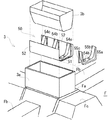
次に、図2に基づいて、内装部材であるコンソールボックス3について説明する。図1でも説明したが、フロア部材Fは上方に突出して車両前後方向に延びるセンタートンネル部Fcと、車幅方向に延びるクロスメンバFbとを有し、クロスメンバFbのセンタートンネル部Fcと交差する部分においてはその上面に沿う突出部Faが形成され、コンソールボックス3は、その突出部Fa上に固定される。
Next, the
コンソールボックス3は、例えば合成樹脂製で、前後左右部に縦壁を有した有底枠体3aと、その枠内に収納され、車両前後方向視略U字状の補強部材50と、補強部材50の内側空間に収納され、合成樹脂製の内箱体3bと、内箱体3bの上方開放部を覆う蓋体(不図示)とから構成されている。内箱体3bは小物入れとして利用される。
The
補強部材50は、左右の側壁部52、52と、これらの下部を連結する底壁部51とで構成されていると共に、側壁部52と底壁部51を架け渡す第2補強部材54a、54b、54cが所定間隔をおいて車両前後方向に亘り配設されている。なお、第2補強部材54a、54b、54cは、そのフランジ部(符号なし)が補強部材50の側壁部52、52の要所部(X印)にて溶接固定されている。
The reinforcing
第2補強部材54a、54b、54cは何れも同じ形状であり、車両前後方向視略U字状で、且つ車幅方向視で下方が開放された断面略コ字状である。即ち、第2補強部材54a、54b、54cは、前面部55a、後面部55c、及びこれらの上端部を連結する連結面部55bとを有した形状に成形されている。そして、連結面部55bにはボルト挿通孔54h、54hが形成されている。
The second reinforcing
したがって、補強部材50の側壁部52、52から底壁部51に渡っては、第2補強部材54a、54b、54cによって複数の閉断面が形成されていることになり、乗員の力でコンソールボックスが変形されることは無い。
Therefore, a plurality of closed sections are formed by the second reinforcing
そして、車両に側突荷重が加わり、シートS1若しくはシートS2がコンソールボックス3に衝突した際は、この閉断面の形成は、補強部材50の左右の側壁部52、52が、単に内方に向かって屈曲するのではなく、適度な変形抵抗を持ち、荷重を吸収する効果を発生する。
When a side impact load is applied to the vehicle and the seat S1 or the seat S2 collides with the
以上から、内装部材であるコンソールボックス3は、まず、有底枠体3aをクロスメンバFbの突出部Fa上に置き、第2補強部材54a、54b、54cが溶接固定されている補強部材50を有底枠体3a内に収納し、次に、ボルト(不図示)をボルト挿通孔54hに通し、フロア部材Fの下部にてナットで締結することにより組み付けられ、その後、内箱体3bを補強部材50上に配設して完成する(図1参照)。
From the above, the
次に、ドアアームレスト7と、シートS1と、内装部材に備えられた補強部材50との位置関係を図3に基づいて説明する。なお、例としてはシートS1についてのみ説明するが、シートS2も以下の説明と同じである。
Next, the positional relationship among the
図3の説明の前に、図1にてシートS1のより詳細な構造を説明する。シートバックフレーム11の車外側辺部11bと下辺部11cの車両前方側面には、シート補強部材15が固定されている。即ち、シート補強部材15は、シートバックフレーム11の車外側辺部11bに沿ってその上方から下端部まで延びる側方部15Aと、側方部15Aの下端部から車室内方に向かって車幅方向に延びる車幅方向補強部15Bとからなり、鋼管材の曲げ加工によって形成されている。車幅方向補強部15Bの車室内方側端部15Eは、シートバックフレーム11の車内側辺部11dよりも更に車室内方にまで延びている。
Prior to the description of FIG. 3, a more detailed structure of the sheet S1 will be described with reference to FIG. A
シート補強部材15は、その車幅方向の耐力がコーナー部の閉断面構造の変形抵抗よりも大きく設定されている。これにより、側突後にシートS1が車室内方に向かって変位してコンソールボックス3に衝突すると、シート補強部材15の車幅方向補強部15Bは、コンソールボックス3に備えられている補強部材50における側壁部52と底壁部51を結ぶコーナー部を押し潰すこととなり、結果、荷重が吸収されると共にクロスメンバFbへ分散されて、シートS2側への荷重の伝達を大幅に低減する。したがって、補強部材50は、シート補強部材15の車幅方向の耐力よりも小さな荷重で変形して、荷重を吸収できる構造であればどんな形状でも良い。なお、側突後の荷重の伝達、及び伝達時の各構成部材の荷重吸収については詳細後述する。
The
また、側方部15Aの上端は、ドアアームレスト7の高さ位置よりも上方であれば良く、車外側辺部11bの上下幅全体に沿うように固定されていても良い。
Moreover, the upper end of 15 A of side parts should just be above the height position of the
図1でも説明したように、シートS1は、スライドレールロア9aとスライドレールアッパ9bとから構成されたスライドレール部材によって車両前後方向にスライド可能である。図3では、最も前方にスライドされた際の上記シート補強部材15の前後方向位置をSf、最も後方にスライドされた際の位置をSr、略中間の位置をScとする。
As described with reference to FIG. 1, the seat S1 is slidable in the vehicle front-rear direction by a slide rail member including a slide rail lower 9a and a slide rail upper 9b. In FIG. 3, the front-rear direction position of the
内装部材に備えられた補強部材50の車両前後方向の幅は、シート補強部材15の前後方向位置が最も前方にスライドされた際の位置Sfから最も後方にスライドされた際の位置Srまでのスライド幅よりもやや長く、位置Sfでは、シート補強部材15の車室内方側端部15Eは、内装部材を補強している補強部材50の第2補強部材54aに対面するようになっており、位置Srでは第2補強部材54cに対面するようになっており、略中間の位置Scでは第2補強部材54bに対面するようになっている。
The width of the reinforcing
そして、シート補強部材15の車室内方側端部15Eは、上記スライド可能範囲であって補強部材50の第2補強部材54a、54b、及び54cに対面しない位置においては、縦壁面部52と対面するようになっている。つまり、シート補強部材15の車室内方側端部15Eは、シートS1が前後方向のどのような位置にあっても内装部材3の補強部材50と対面できる。
The vehicle interior
以上、本発明に係る自動車の側突対応構造として、ドア部材、シート、フロア部材、及び内装部材の配設構造を説明した。次に、上記のような構造により、車両の側突時に乗員の生存空間を確保すると共に、衝突側のシートに伝達された荷重を分散して非衝突側のシートの乗員が受ける荷重を低減できる理由を図4(A)〜(C)を用いて説明する。なお、図4(A)〜(C)において、シートS1は、シートバックフレーム11とシート補強部材15等の骨格部のみを示す。また、シートS1の前後方向位置は、図3で示した位置Scにあるものとする。
As described above, the arrangement structure of the door member, the seat, the floor member, and the interior member has been described as the structure for supporting a side collision of the automobile according to the present invention. Next, with the structure as described above, it is possible to secure the occupant's living space at the time of a side collision of the vehicle and to reduce the load received by the occupant of the non-collision side seat by distributing the load transmitted to the collision side seat. The reason will be described with reference to FIGS. 4A to 4C, the seat S1 shows only the skeleton parts such as the seat back
図4(A)は、車両が側突を受けた時点の車両の状態を示す図である。即ち、シートS1側のドアD1のアウターパネルD1aに、側突してくる車両90のバンパー部材92が衝突している。ドアD1の内部には、アウターパネルD1aの内面に当接するようにインパクトバーIBが設けられている。
FIG. 4A is a diagram illustrating a state of the vehicle at the time when the vehicle receives a side collision. That is, the
図4(B)は、車両が側突を受けた後、ドアアームレストとシートとが衝突した際の車両の状態を示す図である。同図によれば、車両90は、そのバンパー部材92と共にドアD1全体を車室内方に向かって押し潰し、インパクトバーIBも車室内方に屈曲した状態となっている。
FIG. 4B is a diagram illustrating a state of the vehicle when the door armrest and the seat collide after the vehicle receives a side collision. According to the figure, the
また、ドアD1の車室内側に組み付けられているドアトリム部材5には、アームレスト部7が車室内方に向かって突出するように形成されているので、アームレスト部7がスチール製のシートバックフレーム11における車外側辺部11bの縁部11baに挟まれ車幅方向に潰れるように変形している。
Moreover, since the
このように、アームレスト部7がシートバックフレーム11における車外側辺部11bの縁部11baに挟まれ車幅方向に潰れるのは、縁部11baを含むシートバックフレーム11が合成樹脂製のアームレスト部7よりも高い剛性を有しているためである。
As described above, the
図4(C)は、車両90が図4(B)の状態から、更に車室内側にドアD1を押し、シートが車室内方に変位して内装部材に衝突した際の車両の状態を示す図である。
FIG. 4C shows the state of the vehicle when the
図4(C)の状態では、車両90のバンパー92がサイドシル21を乗り越えるようにしてドアD1の下部を車室内方へ押し込んでいる。
In the state of FIG. 4C, the lower part of the door D1 is pushed toward the vehicle interior so that the
これに伴い、シートS1の下方で車幅方向に延びるクロスメンバFbは変形し、車両90から加わった車体下部の衝撃荷重を吸収している。
Along with this, the cross member Fb extending in the vehicle width direction below the seat S1 is deformed to absorb the impact load applied to the lower part of the vehicle body applied from the
一方、ドアD1に加わった荷重は、ドアD1の変形で一部の荷重が吸収され、さらにシートS1のシートバックフレーム11の内、車外側辺部11bの縁部11baとドアトリム部材5が挟まれ、ドアトリム部材5と、これに形成されているドアアームレスト7は、押し潰されている。
On the other hand, a part of the load applied to the door D1 is absorbed by the deformation of the door D1, and further, the edge portion 11ba of the vehicle
したがって、ドアアームレスト7の潰れによって荷重が更に吸収され、シートS1に加わる荷重は小さくなっている。
Therefore, the load is further absorbed by the collapse of the
また、上で説明したように、クロスメンバFbは変形し、ドアトリム部材5及びドアアームレスト7を含むドアD1が侵入してシートS1のシートバックフレーム11を車室内方へ押す荷重とによって、シートS1は車室内方側へ変位していると共に、シートバックフレーム11は僅かな変形が生じている。
Further, as described above, the cross member Fb is deformed, and the door D1 including the door
シートバックフレーム11の変形が僅かなのは、ドアD1へ加わった荷重がドアD1自体の変形による荷重吸収と、ドアトリム部材5及びドアアームレスト7がシートバックフレーム11に挟まれて変形した際の荷重吸収とによりシートS1への荷重が小さくなっていることと、シートS1が大きな変形を防止できる構造とされていることによる。この大きな変形を防止できるシートS1の構造には、3つの特徴がある。
The seat back
その第1は、シートS1のシートバックフレーム11は、上辺部11aと、車外側辺部11bと、車内側辺部11dと、車外側辺部11bの下端部と車内側辺部11dの下端部とを結ぶ下辺部11cとで構成された略矩形状の枠体であり、さらに、車外側辺部11bの車室外方側には縁部11baが、車内側辺部11dの車室内方側には縁部11daが固定されているので車幅方向の荷重に対して変形し難くいことである。
The first is that the seat back
第2は、車外側辺部11bと下辺部11cとで挟まれた角部が、角部補強部材13によって補強されていることである。
Second, the corner portion sandwiched between the vehicle
第3は、鋼管製のシート補強部材15がシートバックフレーム11の車外側辺部11bと下辺部11cに沿うように固定されていることである。
Thirdly, the steel pipe
これら3つの特徴によって、シートS1のシートバックフレーム11は僅かな変形に止まり、これに着座している乗員の生存空間を確保している。
With these three characteristics, the seat back
ここで、シート補強部材15の内、車外側辺部11bに沿う側方部15Aの上端がドアアームレスト7の高さ位置よりも上方になっているのは、ドアアームレスト7がシートバックフレーム11の車外側辺部11bに衝突して内方に荷重を加えてもシート補強部材15がこれを支え、ドアアームレスト7が潰れるようにするためである。
Here, of the
シートS1の車室内方側への変位と荷重吸収の関係について説明する。図4(C)から分かるように、シートS1は、車室内方側へ変位した後、シートS1とシートS2の間で、且つクロスメンバFbの突出部Fa上に固定された内装部材であるコンソールボックス3に衝突してこれをシートS2側に倒れるように変形させている。
The relationship between the displacement of the seat S1 toward the vehicle interior side and load absorption will be described. As can be seen from FIG. 4C, the seat S1 is an interior member fixed between the seat S1 and the seat S2 and on the protrusion Fa of the cross member Fb after being displaced toward the vehicle interior side. It is deformed so that it collides with the
これを詳細に説明すると、シートバックフレーム11の車内側辺部11dに沿って設けられている縁部11daが、コンソールボックス3のシートS1側上部をシートS2側に倒しており、コンソールボックス3のシートS1側下部は、シート補強部材15における車幅方向補強部15Bの車室内方側端部15Eによって押し込まれ、変形している。
Explaining this in detail, the edge 11da provided along the vehicle
図3によれば、側突された時点で車幅方向補強部15Bの車室内方側端部15Eは、コンソールボックス3に備えられた補強部材50の第2補強部材54bと対面しているので、シートS1が車室内方に変位してコンソールボックス3を押す時点では、第2補強部材54bを押すこととなる。ここで、補強部材50は1枚のU字状板材ではなく、第2補強部材54b他を備え、閉断面が形成されているので(図2参照)、単にシートS2の方向に倒れるのではなく、車室内方側端部15Eと衝突する補強部材50の側壁部52と底壁部51を結ぶコーナー部は、前面部55aと後面部55cの適度な変形抵抗により荷重を吸収しつつ潰れ変形を起こす。したがって、この時点でシートS1のシートバックフレーム11及びシート補強部材15に加わっていた荷重は補強部材50で減じられて、さらに補強部材50と連結されているクロスメンバFbの突出部Faに伝達される。この際、シート補強部材15の車幅方向の耐力より小さな荷重で補強部材50が変形するため、シートバックフレーム11が変形せず乗員の生存空間を確保できる。
According to FIG. 3, the vehicle interior
図2で説明したように、フロア部材Fは上方に突出して車両前後方向に延びるセンタートンネル部Fcと、車幅方向に延びるクロスメンバFbとを有し、クロスメンバFbのセンタートンネル部Fcと交差する部分においてはその上面に沿う突出部Faが形成されているものである。したがって、補強部材50と連結されているクロスメンバFbの突出部Faに伝達された荷重は、センタートンネル部Fcを含むフロア部材F全体に広く分散して伝達されることになり、シートS2に加わる荷重は極めて小さくなる。しかも、シートS2に直接、シートS1やコンソールボックス3が衝突しないので、シートS2に着座している乗員へのダメージは殆ど無い。
As described in FIG. 2, the floor member F has a center tunnel portion Fc that protrudes upward and extends in the vehicle front-rear direction, and a cross member Fb that extends in the vehicle width direction, and intersects the center tunnel portion Fc of the cross member Fb. The projecting portion Fa is formed along the upper surface of the portion to be formed. Therefore, the load transmitted to the protruding portion Fa of the cross member Fb connected to the reinforcing
以上、本発明を実施するための最良の形態を、図面に基づいて説明したが、実施の形態は、これに限定されるものではない。 The best mode for carrying out the present invention has been described above with reference to the drawings. However, the embodiment is not limited to this.
3・・・コンソールボックス(内装部材)
5・・・ドアトリム部材
7・・・ドアアームレスト
11・・・シートバックフレーム
11b・・・シートバックフレーム車外側辺部
11c・・・シートバックフレーム下辺部
13・・・角部補強部材
15・・・シート補強部材
15A・・・シート補強部材側方部
15B・・・シート補強部材車幅方向補強部
15E・・・シート補強部材車室内方側端部
50・・・補強部材
51・・・底壁部
52・・・側壁部
54a、54b、54c・・・第2補強部材
Fa・・・クロスメンバ突出部(高強度フロア部材)
Fb・・・クロスメンバ(高強度フロア部材)
D1、D2・・・ドア
S1、S2・・・シート
3. Console box (interior member)
5 ...
Fb: Cross member (high-strength floor member)
D1, D2 ... Doors S1, S2 ... Seat
Claims (1)
前記シートには、シート補強部材が車幅方向に架け渡される一方、
前記内装部材には、前記シート補強部材と車幅方向において対面する補強部材が備えられ、
該補強部材は、前記シート補強部材の車幅方向の耐力より小さな荷重によって変形可能であると共に、車体下部に配設されたフロア部材に接合され、底壁部とその車幅方向両側から上方に向かって立設された側壁部を有して車両前後方向視略U字形状に形成されていると共に、前記底壁部と側壁部とを結ぶコーナー部が前記シート補強部材の車幅方向の耐力より小さな荷重によって変形可能とされ、前記底壁部と側壁部の内側面に沿うと共に前記底壁部および前記側壁部に閉断面を形成する断面略コ字状の第2補強部材を有し、該第2補強部材を介して車体の車幅方向に延設されたクロスメンバに接合されていることを特徴とする自動車の側突対応構造。 A structure for supporting a side collision of an automobile, comprising a pair of seats that are spaced apart in the vehicle width direction in a passenger compartment and having a seat cushion portion and a seat back portion, and an interior member disposed between the pair of seats In
While the seat reinforcing member is bridged in the vehicle width direction on the seat,
The interior member includes a reinforcing member that faces the seat reinforcing member in the vehicle width direction,
The reinforcing member can be deformed by a load smaller than the proof strength of the seat reinforcing member in the vehicle width direction, and is joined to a floor member disposed at the lower part of the vehicle body , and upward from both sides of the bottom wall portion and the vehicle width direction. And a corner portion connecting the bottom wall portion and the side wall portion has a proof strength in the vehicle width direction of the seat reinforcing member. A second reinforcing member that is deformable by a smaller load, has a substantially U-shaped cross section along the inner surface of the bottom wall and the side wall and forms a closed cross section in the bottom wall and the side wall; A structure for dealing with side collision of an automobile, characterized in that the structure is joined to a cross member extending in the vehicle width direction of the vehicle body via the second reinforcing member .
Priority Applications (1)
| Application Number | Priority Date | Filing Date | Title |
|---|---|---|---|
| JP2003300732A JP4300937B2 (en) | 2003-08-26 | 2003-08-26 | Car side impact response structure |
Applications Claiming Priority (1)
| Application Number | Priority Date | Filing Date | Title |
|---|---|---|---|
| JP2003300732A JP4300937B2 (en) | 2003-08-26 | 2003-08-26 | Car side impact response structure |
Publications (2)
| Publication Number | Publication Date |
|---|---|
| JP2005067427A JP2005067427A (en) | 2005-03-17 |
| JP4300937B2 true JP4300937B2 (en) | 2009-07-22 |
Family
ID=34405553
Family Applications (1)
| Application Number | Title | Priority Date | Filing Date |
|---|---|---|---|
| JP2003300732A Expired - Fee Related JP4300937B2 (en) | 2003-08-26 | 2003-08-26 | Car side impact response structure |
Country Status (1)
| Country | Link |
|---|---|
| JP (1) | JP4300937B2 (en) |
Cited By (1)
| Publication number | Priority date | Publication date | Assignee | Title |
|---|---|---|---|---|
| CN103359032A (en) * | 2012-03-26 | 2013-10-23 | 本田技研工业株式会社 | Shock absorption structure of vehicle |
Families Citing this family (12)
| Publication number | Priority date | Publication date | Assignee | Title |
|---|---|---|---|---|
| JP2007290579A (en) * | 2006-04-26 | 2007-11-08 | Nissan Motor Co Ltd | Vehicle body structure, and load transmitting method |
| FR2906198B1 (en) * | 2006-09-27 | 2008-12-26 | Faurecia Interieur Ind Snc | CONSOLE OF A MOTOR VEHICLE DAMPING THE TRANSVERSE FORCES |
| JP5256653B2 (en) * | 2007-06-28 | 2013-08-07 | 日産自動車株式会社 | Car body side impact load support structure and side impact load support method |
| JP2010018226A (en) * | 2008-07-14 | 2010-01-28 | Toyota Motor Corp | Vehicular seat popping out prevention member |
| JP4856731B2 (en) | 2009-02-24 | 2012-01-18 | 本田技研工業株式会社 | Body floor structure |
| JP4914906B2 (en) * | 2009-03-25 | 2012-04-11 | 本田技研工業株式会社 | Body structure |
| JP5639367B2 (en) * | 2010-02-24 | 2014-12-10 | テイ・エス テック株式会社 | Vehicle seat |
| JP5277205B2 (en) * | 2010-06-04 | 2013-08-28 | 本田技研工業株式会社 | Seat back frame structure |
| CN103025571B (en) | 2010-06-04 | 2015-06-10 | 本田技研工业株式会社 | Vehicle seat |
| JP6332112B2 (en) | 2015-04-02 | 2018-05-30 | トヨタ自動車株式会社 | Side impact load transmission structure |
| JP6895236B2 (en) * | 2016-09-08 | 2021-06-30 | ダイキョーニシカワ株式会社 | Vehicle interior structure |
| JP7025286B2 (en) * | 2018-06-08 | 2022-02-24 | トヨタ自動車株式会社 | Vehicle interior structure |
-
2003
- 2003-08-26 JP JP2003300732A patent/JP4300937B2/en not_active Expired - Fee Related
Cited By (1)
| Publication number | Priority date | Publication date | Assignee | Title |
|---|---|---|---|---|
| CN103359032A (en) * | 2012-03-26 | 2013-10-23 | 本田技研工业株式会社 | Shock absorption structure of vehicle |
Also Published As
| Publication number | Publication date |
|---|---|
| JP2005067427A (en) | 2005-03-17 |
Similar Documents
| Publication | Publication Date | Title |
|---|---|---|
| EP1916149B1 (en) | Frame structure of seatback for vehicle | |
| US6299239B1 (en) | Vehicle body structure | |
| JP4539366B2 (en) | Body front structure | |
| JPS6223324Y2 (en) | ||
| JP4300937B2 (en) | Car side impact response structure | |
| JP2007290579A (en) | Vehicle body structure, and load transmitting method | |
| JP2010018190A (en) | Vehicle seat | |
| WO2008047749A1 (en) | Floor underframe for vehicle | |
| JP5353364B2 (en) | Lower body structure of the vehicle | |
| KR20040023489A (en) | Automobile front end body structure | |
| JP5256652B2 (en) | Car body side impact load support structure and side impact load support method | |
| JP2005001473A (en) | Body lower part structure of car | |
| JP2010120525A (en) | Vehicle body lower structure | |
| JP5852623B2 (en) | Body structure | |
| JP4314991B2 (en) | Car body rear structure | |
| JPH07290953A (en) | Chassis frame and body construction for automobile | |
| JP4069833B2 (en) | Front body structure of cab-over type car | |
| JP2005254872A (en) | Safety structure for vehicle | |
| JP2008302911A (en) | Vehicle body structure | |
| JPH09175443A (en) | Lower structure for cab of vehicle | |
| JP5528849B2 (en) | Rear seat back frame used for automobile rear seats | |
| JP4673415B2 (en) | Vehicle seat | |
| JPH06171551A (en) | Automotive lower car body structure | |
| JP6191553B2 (en) | Car door structure | |
| JP6172111B2 (en) | Lower body structure of the vehicle |
Legal Events
| Date | Code | Title | Description |
|---|---|---|---|
| A621 | Written request for application examination |
Free format text: JAPANESE INTERMEDIATE CODE: A621 Effective date: 20060309 |
|
| RD03 | Notification of appointment of power of attorney |
Free format text: JAPANESE INTERMEDIATE CODE: A7423 Effective date: 20060309 |
|
| A131 | Notification of reasons for refusal |
Free format text: JAPANESE INTERMEDIATE CODE: A131 Effective date: 20080924 |
|
| A977 | Report on retrieval |
Free format text: JAPANESE INTERMEDIATE CODE: A971007 Effective date: 20080925 |
|
| A521 | Request for written amendment filed |
Free format text: JAPANESE INTERMEDIATE CODE: A523 Effective date: 20081121 |
|
| TRDD | Decision of grant or rejection written | ||
| A01 | Written decision to grant a patent or to grant a registration (utility model) |
Free format text: JAPANESE INTERMEDIATE CODE: A01 Effective date: 20090331 |
|
| A01 | Written decision to grant a patent or to grant a registration (utility model) |
Free format text: JAPANESE INTERMEDIATE CODE: A01 |
|
| FPAY | Renewal fee payment (event date is renewal date of database) |
Free format text: PAYMENT UNTIL: 20120501 Year of fee payment: 3 |
|
| R150 | Certificate of patent or registration of utility model |
Ref document number: 4300937 Country of ref document: JP Free format text: JAPANESE INTERMEDIATE CODE: R150 Free format text: JAPANESE INTERMEDIATE CODE: R150 |
|
| A61 | First payment of annual fees (during grant procedure) |
Free format text: JAPANESE INTERMEDIATE CODE: A61 Effective date: 20090413 |
|
| FPAY | Renewal fee payment (event date is renewal date of database) |
Free format text: PAYMENT UNTIL: 20130501 Year of fee payment: 4 |
|
| FPAY | Renewal fee payment (event date is renewal date of database) |
Free format text: PAYMENT UNTIL: 20140501 Year of fee payment: 5 |
|
| LAPS | Cancellation because of no payment of annual fees |