JP4298146B2 - Information processing apparatus and method for generating print data - Google Patents
Information processing apparatus and method for generating print data Download PDFInfo
- Publication number
- JP4298146B2 JP4298146B2 JP2000251296A JP2000251296A JP4298146B2 JP 4298146 B2 JP4298146 B2 JP 4298146B2 JP 2000251296 A JP2000251296 A JP 2000251296A JP 2000251296 A JP2000251296 A JP 2000251296A JP 4298146 B2 JP4298146 B2 JP 4298146B2
- Authority
- JP
- Japan
- Prior art keywords
- setting
- page
- job
- preview
- Prior art date
- Legal status (The legal status is an assumption and is not a legal conclusion. Google has not performed a legal analysis and makes no representation as to the accuracy of the status listed.)
- Expired - Fee Related
Links
- 238000000034 method Methods 0.000 title claims description 92
- 230000010365 information processing Effects 0.000 title claims description 23
- 230000008569 process Effects 0.000 claims description 74
- 238000012545 processing Methods 0.000 claims description 73
- 238000003672 processing method Methods 0.000 claims description 12
- 238000006243 chemical reaction Methods 0.000 claims description 10
- 238000003860 storage Methods 0.000 claims description 10
- 238000012546 transfer Methods 0.000 description 52
- 230000008859 change Effects 0.000 description 50
- 230000006870 function Effects 0.000 description 47
- 230000015654 memory Effects 0.000 description 32
- 238000010586 diagram Methods 0.000 description 19
- 239000000463 material Substances 0.000 description 13
- 230000007958 sleep Effects 0.000 description 6
- 230000000694 effects Effects 0.000 description 5
- 230000015572 biosynthetic process Effects 0.000 description 3
- 238000004140 cleaning Methods 0.000 description 3
- 238000003825 pressing Methods 0.000 description 3
- 239000002699 waste material Substances 0.000 description 3
- 239000011248 coating agent Substances 0.000 description 2
- 238000000576 coating method Methods 0.000 description 2
- 239000003086 colorant Substances 0.000 description 2
- 238000012790 confirmation Methods 0.000 description 2
- 230000007246 mechanism Effects 0.000 description 2
- 230000009467 reduction Effects 0.000 description 2
- 229910052782 aluminium Inorganic materials 0.000 description 1
- XAGFODPZIPBFFR-UHFFFAOYSA-N aluminium Chemical compound [Al] XAGFODPZIPBFFR-UHFFFAOYSA-N 0.000 description 1
- 230000002457 bidirectional effect Effects 0.000 description 1
- 239000011230 binding agent Substances 0.000 description 1
- 238000004364 calculation method Methods 0.000 description 1
- 238000004891 communication Methods 0.000 description 1
- 238000007796 conventional method Methods 0.000 description 1
- 238000013500 data storage Methods 0.000 description 1
- 238000005034 decoration Methods 0.000 description 1
- 238000011161 development Methods 0.000 description 1
- 238000010438 heat treatment Methods 0.000 description 1
- 230000002452 interceptive effect Effects 0.000 description 1
- 238000007726 management method Methods 0.000 description 1
- 229910052751 metal Inorganic materials 0.000 description 1
- 239000002184 metal Substances 0.000 description 1
- 230000003287 optical effect Effects 0.000 description 1
- 238000004080 punching Methods 0.000 description 1
- 238000009877 rendering Methods 0.000 description 1
- 230000004044 response Effects 0.000 description 1
- 238000004804 winding Methods 0.000 description 1
Images


Classifications
-
- G—PHYSICS
- G06—COMPUTING; CALCULATING OR COUNTING
- G06K—GRAPHICAL DATA READING; PRESENTATION OF DATA; RECORD CARRIERS; HANDLING RECORD CARRIERS
- G06K15/00—Arrangements for producing a permanent visual presentation of the output data, e.g. computer output printers
- G06K15/02—Arrangements for producing a permanent visual presentation of the output data, e.g. computer output printers using printers
-
- G—PHYSICS
- G06—COMPUTING; CALCULATING OR COUNTING
- G06K—GRAPHICAL DATA READING; PRESENTATION OF DATA; RECORD CARRIERS; HANDLING RECORD CARRIERS
- G06K2215/00—Arrangements for producing a permanent visual presentation of the output data
- G06K2215/0002—Handling the output data
- G06K2215/0077—Raster outputting to the print element(s)
Landscapes
- Engineering & Computer Science (AREA)
- General Engineering & Computer Science (AREA)
- Physics & Mathematics (AREA)
- General Physics & Mathematics (AREA)
- Theoretical Computer Science (AREA)
- Record Information Processing For Printing (AREA)
Description
【0001】
【発明の属する技術分野】
本発明は、印刷データを生成する情報処理装置および方法、記憶媒体に関するもので、特に、アプリケーションにより生成される印刷データの印刷設定を考慮したプレビューを表示させるよう制御する情報処理装置および情報処理方法およびその情報処理方法を実行するコンピュータ可読のプログラムを格納した記憶媒体に関するものである。
【0002】
【従来の技術】
クライアントコンピュータにおいてあるアプリケーションにより生成したドキュメント(文書データ)を印刷する際、近年では高機能なプリンタドライバを用いて、様々なレイアウトを指定して印刷できるようになってきた。そしてレイアウトの設定が複雑になるに従い、こと前に出力結果をホストの画面上で確認(プレビュー)することは、望む印刷結果を無駄なく早く手に入れるためには効果的な方法である。
【0003】
そして、印刷前にクライアントコンピュータ(ホストコンピュータ)の画面上にプレビューする機能を、各アプリケーションが独自に提供するのが一般的であり、この場合、アプリケーションの持つレイアウト機能を適用した結果のプレビューを画面上で確認することができる。
【0004】
しかし、従来の方法では、プリンタなどの印刷装置およびそのプリンタ用のプリンタドライバが提供するレイアウト機能が確認できない。特に、プリンタ本体が備える特殊な機能をプレビューすることはできなかった。たとえば、PSプリンタの、色反転(ネガティブ)印刷、左右反転(ミラー)印刷などの機能をプレビューすることはできないという問題があった。
【0005】
【発明が解決しようとしている課題】
本発明は上記問題点を解決するためになされたものであり、印刷設定の中からプリンタ本体の特別な機能の設定を検出しその設定にあわせクライアントコンピュータ上でプリンタの機能をシミュレートしてプレビュー表示することを可能とする。
【0006】
【課題を解決するための手段】
上記目的を達成する本発明の情報処理装置及び方法、記憶媒体は、以下に示す構成を備えることを特徴とする。
【0007】
即ち、本発明にかかる情報処理装置は、印刷装置で印刷される印刷ジョブを生成する情報処理装置であって、
ページに対する綴じ代の位置、および、ページを左右反転する鏡像印刷属性を印刷データの処理条件として設定する設定手段と、
出力結果を確認するためのプレビュー画像を表示することを指定する指定手段と、
アプリケーションより出力された印刷データを中間コード形式に変換し、該変換された中間コード形式のデータと、前記印刷データの処理条件とを保存する中間データ変換手段と、
前記指定手段によって前記プレビュー画像を表示することが指定された場合、前記設定手段による設定内容と、前記アプリケーションから出力された前記印刷データから変換された前記中間コード形式のデータとに基づいて、前記綴じ代の位置を前記設定手段によって設定された位置に保持し、前記印刷データに基づく画像を左右反転させたプレビュー画像を表示するプレビュー表示制御手段と、
前記プレビュー表示制御手段が前記プレビュー画像を表示した後で、前記中間データ変換手段により保存された前記中間コード形式のデータに基づいて、印刷ジョブを生成するジョブ生成手段とを備え、
前記中間コード形式のデータは、前記印刷ジョブの生成と前記プレビュー画像の表示との両者に用いられることを特徴とする。
【0008】
また、本発明にかかる情報処理方法は、印刷装置で印刷される印刷ジョブを生成する情報処理装置において実行される情報処理方法であって、
ページに対する綴じ代の位置、および、ページを左右反転する鏡像印刷属性を印刷データの処理条件として設定する設定工程と、
出力結果を確認するためのプレビュー画像を表示することを指定する指定工程と、
アプリケーションより出力された印刷データを中間コード形式に変換し、該変換された中間コード形式のデータと、前記印刷データの処理条件とを保存する中間データ変換工程と、
前記指定工程において前記プレビュー画像を表示することが指定された場合、前記設定工程において設定された設定内容と、前記アプリケーションから出力された前記印刷データから変換された前記中間コード形式のデータとに基づいて、前記綴じ代の位置を前記設定工程で設定された位置に保持し、前記印刷データに基づく画像を左右反転させたプレビュー画像を表示するプレビュー表示制御工程と、
前記プレビュー表示制御工程により前記プレビュー画像が表示された後で、前記中間データ変換工程により保存された前記中間コード形式のデータに基づいて、印刷ジョブを生成するジョブ生成工程とを備え、
前記中間コード形式のデータは、前記印刷ジョブの生成と前記プレビュー画像の表示との両者に用いられることを特徴とする。
【0010】
【発明の実施形態】
<第1の実施形態>
以下、本発明を適用するのに好適である実施形態について説明を行う。
【0011】
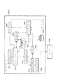
図1は本発明の実施形態を示すプリンタ制御システムの構成を説明するブロック図である。なお、本発明の機能が実行されるのであれば、単体の機器であっても、複数の機器からなるシステムであっても、LAN,WAN等のネットワークを介して接続がなされ処理が行われるシステムであっても本発明を適用できる。
【0012】
同図において、ホストコンピュータ3000は、ROM3のプログラム用ROMあるいは外部メモリ11に記憶された文書処理プログラム等に基づいて図形、イメージ、文字、表(表計算等を含む)等が混在した文書処理を実行するCPU1を備え、システムバス4に接続される各デバイスをCPU1が総括的に制御する。また、このROM3のプログラム用ROMあるいは外部メモリ11には、CPU1の制御プログラムであるオペレーティングシステムプログラム(以下OS)等を記憶し、ROM3のフォント用ROMあるいは外部メモリ11には上記文書処理の際に使用するフォントデータ等を記憶し、ROM3のデータ用ROMあるいは外部メモリ11には上記文書処理等を行う際に使用する各種データを記憶する。RAM2は、CPU1の主メモリ、ワークエリア等として機能する。
【0013】
キーボードコントローラ(KBC)5は、キーボード9や不図示のポインティングデバイスからのキー入力を制御する。CRTコントローラ(CRTC)6は、CRTディスプレイ(CRT)10の表示を制御する。7はディスクコントローラ(DKC)で、ブートプログラム、各種のアプリケーション、フォントデータ、ユーザファイル、編集ファイル、プリンタ制御コマンド生成プログラム(以下プリンタドライバ)等を記憶するハードディスク(HD)、フロッピーディスク(FD)等の外部メモリ11とのアクセスを制御する。プリンタコントローラ(PRTC)8は、双方向性インタフェイス(インタフェイス)21を介してプリンタ1500に接続されて、プリンタ1500との通信制御処理を実行する。
【0014】
なお、CPU1は、例えばRAM2上に設定された表示情報をRAMへのアウトラインフォントの展開(ラスタライズ)処理を実行し、CRT10上でのWYSIWYGを可能としている。また、CPU1は、CRT10上の不図示のマウスカーソル等で指示されたコマンドに基づいて登録された種々のウインドウを開き、種々のデータ処理を実行する。ユーザは印刷を実行する際、印刷の設定に関するウインドウを開き、プリンタの設定や、印刷モードの選択を含むプリンタドライバに対する印刷処理方法の設定を行える。
【0015】
プリンタ1500は、CPU12により制御される。プリンタCPU12は、ROM13のプログラム用ROMに記憶された制御プログラム等あるいは外部メモリ14に記憶された制御プログラム等に基づいてシステムバス15に接続される印刷部(プリンタエンジン)17に出力情報としての画像信号を出力する。また、このROM13のプログラムROMには、CPU12の制御プログラム等を記憶する。ROM13のフォント用ROMには上記出力情報を生成する際に使用するフォントデータ等が記憶され、ROM13のデータ用ROMには、ハードディスク等の外部メモリ14がないプリンタの場合には、ホストコンピュータ上で利用される情報等が記憶されている。
【0016】
CPU12は入力部18を介してホストコンピュータとの通信処理が可能となっており、プリンタ内の情報等をホストコンピュータ3000に通知できる。RAM19は、CPU12の主メモリや、ワークエリア等として機能するRAMで、図示しない増設ポートに接続されるオプションRAMによりメモリ容量を拡張することができるように構成されている。なお、RAM19は、出力情報展開領域、環境データ格納領域、NVRAM等に用いられる。前述したハードディスク(HD)、ICカード等の外部メモリ14は、メモリコントローラ(MC)20によりアクセスを制御される。外部メモリ14は、オプションとして接続され、フォントデータ、エミュレーションプログラム、フォームデータ等を記憶する。また、18は前述した操作パネルで操作のためのスイッチおよびLED表示器等が配されている。
【0017】
また、前述した外部メモリ14は1個に限らず、複数個備えられ、内蔵フォントに加えてオプションカード、言語系の異なるプリンタ制御言語を解釈するプログラムを格納した外部メモリを複数接続できるように構成されていてもよい。更に、図示しないNVRAMを有し、操作パネル1501からのプリンタモード設定情報を記憶するようにしてもよい。
【0018】
図2は、プリンタ等の印刷装置が直接接続されているか、あるいはネットワーク経由で接続されているホストコンピュータにおける典型的な印刷処理の構成図である。アプリケーション201、グラフィックエンジン202、プリンタドライバ203、およびシステムスプーラ204は、外部メモリ11に保存されたファイルとして存在し、実行される場合にOSやそのモジュールを利用するモジュールによってRAM2にロードされ実行されるプログラムモジュールである。
【0019】
また、アプリケーション201およびプリンタドライバ203は、外部メモリ11のFDや不図示のCD?ROM、あるいは不図示のネットワークを経由して外部ディスク11のHDに追加することが可能となっている。外部メモリ11に保存されているアプリケーション201はRAM2にロードされて実行されるが、このアプリケーション201からプリンタ1500に対して印刷を行う際には、同様にRAM2にロードされ実行可能となっているグラフィックエンジン202を利用して出力(描画)を行う。
【0020】
グラフィックエンジン202は、印刷装置ごとに用意されたプリンタドライバ203を同様に外部メモリ11からRAM2にロードし、アプリケーション201の出力をプリンタドライバ203に設定する。そして、アプリケーション201から受け取るGDI(Graphic Device Interface)関数からDDI(Device Driver Interface)関数に変換して、プリンタドライバ203へDDI関数を出力する。プリンタドライバ203は、グラフィックエンジン202から受け取ったDDI関数に基づいて、プリンタが認識可能な制御コマンド、例えばPDL(Page Description Language)に変換する。変換されたプリンタ制御コマンドは、OSによってRAM2にロードされたシステムスプーラ204を経てインタフェイス21経由でプリンタ1500へ印刷データとして出力される仕組みとなっている。
【0021】
本実施形態の印刷システムは、図2で示すプリンタ1500とホストコンピュータ3000からなる印刷システムに加えて、更に図3に示すように、アプリケーションからの印刷データを一旦中間コードデータでスプールする構成を有する。
【0022】
図3は、図2のシステムを拡張したもので、グラフィックエンジン202からプリンタドライバ203へ印刷命令を送る際に、一旦中間コードからなるスプールファイル303を生成する構成をとる。図2のシステムでは、アプリケーション201が印刷処理から開放されるのはプリンタドライバ203がグラフィックエンジン202からのすべての印刷命令をプリンタの制御コマンドへ変換し終った時点である。これに対して、図3のシステムでは、スプーラ302がすべての印刷命令を中間コードデータに変換し、スプールファイル303に出力した時点である。通常、後者の方が短時間で済む。
【0023】
また、図3で示すシステムにおいては、スプールファイル303の内容に対して加工することができる。これによりアプリケーションからの印刷データに対して、拡大縮小や、複数ページを1ページに縮小して印刷する等、アプリケーションの持たない機能を実現することができる。
【0024】
これらの目的のために、図2のシステムに対し、図3のように中間コードデータでスプールするように、システムの拡張がなされてきている。なお、印刷データの加工を行うためには、通常プリンタドライバ203が提供するウインドウから設定を行い、プリンタドライバ203がその設定内容をRAM2上あるいは外部メモリ11上に保管する。
【0025】
以下、図3の詳細を説明する。図に示す通り、この拡張された処理方式では、グラフィックエンジン202からの印刷命令であるDDI関数をディスパッチャ301が受け取る。ディスパッチャ301がグラフィックエンジン202から受け取った印刷命令(DDI関数)が、アプリケーション201からグラフィックエンジン202へ発行された印刷命令(GDI関数)に基づくものである場合には、ディスパッチャ301は外部メモリ11に格納されているスプーラ302をRAM2にロードし、プリンタドライバ203ではなくスプーラ302へ印刷命令(DDI関数)を送付する。
【0026】
スプーラ302は受け取った印刷命令を解析し、ページ単位に中間コードに変換してスプールファイル303に出力する。このページ単位に格納されている中間コードのスプールファイルをページ描画ファイル(PDF:Page Description File)と呼ぶ。また、スプーラ302は、プリンタドライバ203に対して設定されている印刷データに関する加工設定(Nup、両面、ステイプル、カラー/モノクロ指定等)をプリンタドライバ203から取得してジョブ単位のファイルとしてスプールファイル303に保存する。このジョブ単位に格納されている設定ファイルをジョブ設定ファイル(簡略してSDF:Spool Description Fileと呼ぶこともある)と呼ぶ。このジョブ設定ファイルについては後述する。
【0027】
なお、スプールファイル303は外部メモリ11上にファイルとして生成するが、RAM2上に生成されても構わない。更にスプーラ302は、外部メモリ11に格納されているスプールファイルマネージャ304をRAM2にロードし、スプールファイルマネージャ304に対してスプールファイル303の生成状況を通知する。その後、スプールファイルマネージャ304は、スプールファイル303に保存された印刷データに関する加工設定の内容に従って印刷を行えるか判断する。
【0028】
スプールファイルマネージャ304がグラフィックエンジン202を利用して印刷を行えると判断した際には、外部メモリ11に格納されているデスプーラ305をRAM2にロードし、デスプーラ305に対して、スプールファイル303に記述された中間コードのページ描画ファイルの印刷処理を行うように指示する。
【0029】
デスプーラ305はスプールファイル303に含まれる中間コードのページ描画ファイルをスプールファイル303に含まれる加工設定情報を含むジョブ設定ファイルに従って加工し、GDI関数を再生成し、もう一度グラフィックエンジン202経由でGDI関数を出力する。
【0030】
ディスパッチャ301がグラフィックエンジン202から受け取った印刷命令(DDI関数)がデスプーラ305からグラフィックエンジン202へ発行された印刷命令(GDI関数)に基づいたものである場合には、ディスパッチャ301はスプーラ302ではなく、プリンタドライバ203に印刷命令を送る。
【0031】
プリンタドライバ203はグラフィックエンジン202から取得したDDI関数に基づいてページ記述言語等からなるプリンタ制御コマンドを生成し、システムスプーラ204経由でプリンタ1500に出力する。
【0032】
更に、図3では、これまで説明した拡張システムに加えて、プレビューア306、設定変更エディタ307を配し、プレビュー、印刷設定変更、複数ジョブの結合を可能にした構成例を示している。
【0033】
印刷プレビュー、印刷設定変更、複数ジョブの結合を行うためには、まずユーザが図9に示すプリンタドライバのプロパティにおいて、「出力先の指定」を行う手段であるプルダウンメニューにおいて「ストア(Store)」を指定する必要がある。なお、プレビューだけをみたい場合は、出力先の指定として「プレビュー(Preview)」を選択することによっても可能である。
【0034】
このようにプリンタドライバのプロパティで設定されている内容は設定ファイルとしてOSが提供する構造体(WindowsOSでは、DEVMODEと呼ばれる)に格納される。その構造体には、例えばスプールファイル303に含まれる加工設定中にスプールファイルマネージャ304にストアを行うかどうかの設定が含まれており、スプールファイルマネージャ304がプリンタドライバを介して加工設定を読み込み、ストア指定がなされていた場合、前述したようにスプールファイル303にページ描画ファイルとジョブ設定ファイルとが生成・格納され、図16のようにスプールファイルマネージャのウインドウ画面がポップアップされ、スプールファイル303にスプールされたジョブがリスト表示される。
【0035】
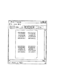
図16には、4つのジョブがスプールされている例を示しており、メニューバーもしくは、そのすぐ下のメニューアイコンを押下することにより、ジョブの操作を行うことができる。メニューバーとメニューアイコンの操作の数は同じである。操作種類としては、ジョブを選択した状態で、「印刷」、中間コードのスプールファイルをそのまま残して印刷を行わせる「セーブして印刷」、印刷設定を考慮したジョブの出力プレビューを見るための「プレビュー」、中間コードのスプールファイルを削除する「削除」、中間コードのスプールファイルのコピーを生成する「複製」、複数の中間コードのスプールファイルのジョブを結合して1つのジョブにする「結合」、結合ジョブを元の複数のジョブに分割する「分割」、単体ジョブもしくは結合ジョブの印刷設定(レイアウト設定やフィニッシング設定等)を変更する「ジョブ編集」、あるジョブの印刷順序を最初にする「先頭に移動」、あるジョブの印刷順序を1つ早くする「1つ上に移動」、あるジョブの印刷順序を1つお則する「1つ下に移動」、あるジョブの印刷順序を最後にする「最後に移動」の以上11個の操作がある。
【0036】
スプールファイルマネージャのウインドウ画面(図16)上で、ある単体ジョブもしくは結合ジョブのプレビュー指定がされた場合、外部メモリ11に格納されているプレビューア306をRAM2にロードし、プレビューア306に対して、スプールファイル303に記述された中間コードのジョブのプレビュー処理を行うように指示する。
【0037】
プレビューア306はスプールファイル303に含まれる中間コードのページ描画ファイル(PDF)を順次読み出し、スプールファイル303に格納されているジョブ設定ファイル(SDF)に含まれる加工設定情報の内容に従って加工し、グラフィックエンジン202に対してGDI関数を出力し、グラフィックエンジン202が自身のクライアント領域に描画データを出力することによって、画面上の出力が可能となる。
【0038】
グラフィックエンジン202は、指定された出力先に応じて適切なレンダリングを行うことが可能である。このことから、プレビューア306は、デスプーラ305同様に、スプールファイル303に含まれる中間コードをスプールファイル303に含まれる加工設定の内容に従って加工し、グラフィックエンジン202を利用して出力する方法で実現可能となる。このようにプリンタドライバで設定されている加工設定をジョブ設定ファイルとしてスプールファイル303に格納し、このジョブ設定ファイルに基づいてページ描画ファイルのデータを加工して出力することにより、実際の描画データがどのように印刷されるか、更には、Nup(Nページの論理ページを1ページの物理ページに縮小配置して印刷する処理)指定されている場合、両面印刷されている場合、製本印刷指定されている場合、スタンプが指定されている場合、それぞれに応じて、プリンタで出力されるものに近い印刷プレビューをユーザに提供することができる。
【0039】
なお、従来の文書作成等のアプリケーションソフトウェアが有しているプレビュー機能は、あくまでそのアプリケーションにおけるページ設定に基づいて描画しているため、プリンタドライバでの印刷設定が反映されず、実際に印刷出力されるプレビューをユーザに認識させることはできなかった。
【0040】
上記のようにプレビュー処理を行うことにより、図17のようにスプールファイル303に含まれる印刷の加工設定の大プレビューがプレビューア306によって画面上に表示され、その後、ユーザの非表示指示によって、プレビューア306がクローズされ、制御がスプールファイルマネージャのウインドウ画面(図16)に移行する。
【0041】
そして、ユーザがプレビューア306によって表示された内容に従って、印刷を行うならば、スプールファイルマネージャ304上で、「印刷」もしくは「セーブして印刷」を指示することにより印刷要求を発行する。印刷要求は前述したように、デスプーラ305によりジョブ設定ファイルに基づいてページ描画ファイルを加工してGDI関数を生成し、グラフィックエンジン202に伝えられ、ディスパッチャ301経由で、プリンタドライバ203に印刷命令が送られ、印刷が実行される。
【0042】
次に、設定変更エディタ307を用いた設定変更について説明する。
【0043】
その実現方法としては、プレビュー同様、図9において「ストア(Store)」を指定されたジョブに関して設定可能である。同様のフローによりスプールファイルマネージャ304がポップアップされ、スプールされたジョブがリスト表示される。スプールファイルマネージャのウインドウ画面(図16)上で、「ジョブ編集」が指定され、設定変更指示がされた場合、外部メモリ11に格納されている設定変更エディタ307をRAM2にロードし、設定変更エディタ307に対して、現在またはデフォルトの加工設定の表示を行うように指示する。そして図18のようなジョブ設定画面が表示される。
【0044】
設定変更エディタ307は、「ジョブ編集」が指定されたジョブのジョブ設定ファイルをスプールファイル303から取得し、そのジョブ設定ファイルに指定されている設定項目に基づいて図18のジョブ設定画面のデフォルト値を変更する。図18に示す例では、「ジョブ編集」指定されたジョブのジョブ設定ファイルには、部数:1部、印刷方法:片面、ステイプル:なし、レイアウト:1ページ/枚等が指定されていることになる。
【0045】
この設定変更エディタ307でもスプールファイル303に含まれる中間コードのページ描画ファイルをスプールファイル303に格納されているジョブ設定ファイルに含まれる加工設定の内容に従って加工し、グラフィックエンジン202を用いて自身のクライアント領域に出力することによって、図18に示す画面上の小プレビュー出力が可能となる。
【0046】
また、ここで、スプールファイル303に格納されているジョブ設定ファイルに含まれる加工設定の内容を変更、修正することが可能である。その際、プリンタドライバ203の設定可能な項目を設定変更エディタ307上のユーザインターフェイスに持っていても、プリンタドライバ203自身のユーザインターフェイスを呼び出しても構わない。図18に示すように、分数、印刷方法(片面、両目、製本印刷)、ステイプル(サドルフィニッシャー等)、ページレイアウト、配置順等の指定ができ、また「詳細設定」を押下することにより、プリンタドライバで指定できる項目の大半を設定しなおすことが可能となる。ただし、解像度、グラフィックモード等の印刷品位に関する設定の変更は許可しないものとする。
【0047】
ここで変更された変更項目は設定変更エディタ307上の認証要求に従い、変更が認証され、制御がスプールファイルマネージャ304に移行する。変更が認証されたものは、印刷設定の変更を保存することになるが、オリジナルのジョブ設定ファイルには保存せずに、ジョブ編集等で用いられるジョブ出力用設定ファイルを新たに生成して保存することになる。ジョブ出力用設定ファイルについての詳細は、図10以降で後述する。
【0048】
そして、ユーザがプレビューア306での確認同様、設定変更内容に従って、印刷を行うならば、スプールファイルマネージャ304上で、印刷要求を発行する。印刷要求はグラフィックエンジン202に伝えられ、ディスパッチャ301経由で、プリンタドライバ203に印刷命令が送られ、印刷が実行される。
【0049】
また、スプールファイルマネージャのウインドウ画面(図16)では、複数の印刷ジョブを結合し、一つの印刷ジョブとして印刷するように指定することが可能である。これも、プレビュー、設定変更同様、図9のプリンタドライバのプロパティにおいて出力先を「ストア(Store)」指定されたジョブが前提となる。
【0050】
ユーザが印刷ジョブの結合を行う場合、まず、アプリケーション201からプリンタドライバ203を呼び出し、図9に示すようなユーザインターフェイス上からストアを選択する。前記同様、この選択により、スプールファイル303にストアされ、図16のようにスプールファイルマネージャのウインドウ画面(図16)がポップアップされる。スプールされたジョブはスプールファイルマネージャのウインドウ上にリスト表示される。アプリケーション201から同様の操作をすることにより、スプールファイルマネージャ304上に複数ジョブのリスト表示がされることになる。
【0051】
ここで、複数ジョブを選択し、「結合」が指定された場合、外部メモリ11に格納されている設定変更エディタ307をRAM2にロードし、設定変更エディタ307に対して、リスト上の先頭ジョブまたはデフォルトの加工設定の表示を行うように指示する。そして図18のような結合設定画面が表示される。ここでは、設定変更エディタ307を結合設定画面として用いているが、別モジュールのものを用いても構わない。
【0052】
この設定変更エディタ307は、スプールファイル303に含まれる中間コードのページ描画ファイルをスプールファイル303に格納されているジョブ設定情報に含まれる加工設定の内容に従って加工し、結合ジョブとして指定されたすべてのジョブに対して、グラフィックエンジン202を用いて自身のクライアント領域に出力することによって、画面上の出力を行う。その際、図18に示すプレビュー領域に選択された全てのジョブの小プレビューが可能となる。また、結合ジョブを生成する際に、それぞれの単体ジョブのジョブ設定ファイルを拡張したジョブ出力用設定ファイルを生成する。このジョブ出力用設定ファイルは、ジョブ編集を行う際にも生成されるものであり、1つのジョブに対して1つできるものであり、結合ジョブの場合もまた1つ生成される。
【0053】
ここではそれぞれのジョブに対して、結合する前の加工設定で表示することも、結合ジョブとして統一の加工設定に変更、修正して表示することも可能である。その際、プリンタドライバ203の設定可能な項目を設定変更エディタ307上のユーザインターフェイスに持っていても、プリンタドライバ203自身のユーザインターフェイスを呼び出しても構わない。
【0054】
ここで結合されたジョブ及び変更された変更項目は、前述したように、設定変更エディタ307上の認証要求に従い、変更が認証され、制御がスプールファイルマネージャ304に移行する。これらの操作により、先に選択された複数ジョブは、スプールファイルマネージャのウインドウ上で一つの結合ジョブとして表示される。
【0055】
そして、ユーザがプレビューア306での確認同様、設定変更内容に従って、印刷を行うならば、スプールファイルマネージャ304上で、印刷要求を発行する。印刷要求はグラフィックエンジン202に伝えられ、ディスパッチャ301経由で、プリンタドライバ203に印刷命令が送られ、印刷が実行される。
【0056】
図4は、プリンタ1500の一例である両面印刷機能を有するカラーレーザプリンタの断面図である。
【0057】
このプリンタはホストコンピュータ3000より入力した印刷データに基づいて得られる各色毎の画像データで変調されたレーザ光をポリゴンミラー31により感光ドラム15を走査して静電潜像を形成する。そして、この静電潜像をトナー現像して可視画像を得、これを中間転写体9へ全色について多重転写してカラー可視画像を形成する。そして更に、このカラー可視画像を転写材2へ転写し、転写材2上にカラー可視画像を定着させる。以上の制御を行う画像形成部は、感光ドラム15を有するドラムユニット、接触帯電ローラ17を有する一次帯電部、クリーニング部、現像部、中間転写体9、用紙カセット1や各種ローラ3、4、5、7を含む給紙部、転写ローラ10を含む転写部及び定着部25によって構成されている。
【0058】
ドラムユニット13は、感光ドラム(感光体)15と感光ドラム15のホルダを兼ねたクリーニング機構を有するクリーナ容器14とを一体に構成したものである。このドラムユニット13はプリンタ本体に対して着脱自在に支持され、感光ドラム15の寿命に合わせて容易にユニット交換可能に構成されている。上記感光ドラム15はアルミシリンダの外周に有機光導電体層を塗布して構成し、クリーナ容器14に回転可能に支持されている。感光ドラム15は、図示しない駆動モータの駆動力が伝達されて回転するもので、駆動モータは感光ドラム15を画像形成動作に応じて反時計回り方向に回転させる。感光ドラム15の表面を選択的に露光させることにより静電潜像が形成されるように構成されている。スキャナ部30では、変調されたレーザ光を、モータ31aにより画像信号の水平同期信号を同期して回転するポリゴンミラーにより反射し、レンズ32、反射鏡33を介して感光ドラムを照射する。
【0059】
現像部は、上記静電潜像を可視画像化するために、イエロー(Y)、マゼンダ(M)、シアン(C)の現像を行う3個のカラー現像器20Y、20M、20Cと、ブラック(B)の現像を行う1個のブラック現像器21Bとを備えた構成を有する。カラー現像器20Y、20M、20C及びブラック現像器21Bには、スリープ20YS、20MS、20CS及び21BSと、これらスリープ20YS、20MS、20CS、21BSそれぞれの外周に圧接する塗布ブレード20YB、20MB、20CB及び21BBとがそれぞれ設けられる。また3個のカラー現像器20Y、20M、20Cには塗布ローラ20YR、20MR、20CRが設けられている。
【0060】
また、ブラック現像器21Bはプリンタ本体に対して着脱可能に取り付けられており、カラー現像器20Y、20M、20Cは回転軸22を中心に回転する現像ロータリー23にそれぞれ着脱可能に取り付けられている。
【0061】
ブラック現像器21Bのスリープ21BSは感光ドラム15に対して例えば300μm程度の微小間隔を持って配置されている。ブラック現像器21Bは、器内に内蔵された送り込み部材によってトナーを搬送すると共に、時計回り方向に回転するスリープ21BSの外周に塗布ブレード21BBによって塗布するように摩擦帯電によってトナーへ電荷を付与する。また、スリープ21BSに現像バイアスを印加することにより、静電潜像に応じて感光ドラム15に対して現像を行って感光ドラム15にブラックトナーによる可視画像を形成する。
【0062】
3個のカラー現像器20Y、20M、20Cは、画像形成に際して現像ロータリー23の回転に伴って回転し、所定のスリープ20YS、20MS、20CSが感光ドラム15に対して300μm程度の微小間隔を持って対向することになる。これにより所定のカラー現像器20Y、20M、20Cが感光ドラム15に対向する現像位置に停止し、感光ドラム15に可視画像が作成される。
【0063】
カラー画像形成時には、中間転写体9の1回転毎に現像ロータリー23が回転し、イエロー現像器20Y、マゼンダ現像器20M、シアン現像器20C、次いでブラック現像器21Bの順で現像工程がなされ、中間転写体9が4回転してイエロー、マゼンダ、シアン、ブラックのそれぞれのトナーによる可視画像を順次形成し、その結果フルカラー可視画像を中間転写体9上に形成する。
【0064】
中間転写体9は、感光ドラム15に接触して感光ドラム15の回転に伴って回転するように構成されたもので、カラー画像形成時に時計回り方向に回転し、感光ドラム15から4回の可視画像の多重転写を受ける。また、中間転写体9は画像形成時に後述する転写ローラ10が接触して転写材2を挟持搬送することにより転写材2に中間転写体9上のカラー可視画像を同時に多重転写する。中間転写体の外周部には、中間転写体9の回転方向に関する位置を検知するためのTOPセンサ9a及びRSセンサ9bと、中間転写体に転写されたトナー像の濃度を検知するための濃度センサ9cが配置されている。
【0065】
転写ローラ10は、感光ドラム15に対して接離可能に支承された転写帯電器を備えたもので、金属軸を中抵抗発泡弾性体により巻回することによって構成されている。
【0066】
転写ローラ10は、図4に実線で示すように中間転写体9上にカラー可視画像を多重転写している間は、カラー可視画像を乱さぬように下方に離開している。そして、上記中間転写体9上に4色のカラー可視画像が形成された後は、このカラー可視画像を転写材2に転写するタイミングに合わせてカム部材(不図示)により転写ローラ10を図示点線で示す上方に位置させる。これにより転写ローラ10は転写材2を介して中間転写体9に所定の押圧力で圧接すると共に、バイアス電圧が印加され、中間転写体9上のカラー可視画像が転写材2に転写される。
【0067】
定着部25は、転写2を搬送させながら、転写されたカラー可視画像を定着させるものであり、転写材2を加熱する定着ローラ26と転写材2を定着ローラ26に圧接させるための加圧ローラ27とを備えている。定着ローラ26と加圧ローラ27とは中空状に形成され、内部にそれぞれヒータ28、29が内蔵されている。即ち、カラー可視画像を保持した転写材2は定着ローラ26と加圧ローラ27とにより搬送されると共に、熱及び圧力を加えることによりトナーが表面に定着される。
【0068】
可視画像定着後の転写材2は、その後排紙ローラ34、35、36によって排紙部37へ排出して画像形成動作を終了する。
【0069】
クリーニング手段は、感光ドラム15上及び中間転写体9上に残ったトナーをクリーニングするものであり、感光ドラム15上に形成されたトナーによる可視画像を中間転写体9に転写した後の廃トナーあるいは、中間転写体9上に作成された4色のカラー可視画像を転写材2に転写した後の廃トナーは、クリーナ容器14に蓄えられる。
【0070】
印刷される転写材(記録用紙)2は、給紙トレイ1から給紙ローラ3により取り出されて中間転写体9と転写ローラ10との間に挟まれるようにして搬送されてカラートナー画像が記録され、定着部25を通過してトナー像が定着される。片面印刷の場合には、案内38が上方の排紙部に記録用紙を導くように搬送経路を形成するが、両面印刷に対しては、下方の両面ユニットに導くように経路を形成する。
【0071】
両面ユニットに導かれた記録用紙は、搬送ローラ40によりトレイ1の下部(二点鎖線で示す搬送経路)に一旦送り込まれた後に逆方向に搬送され、両面トレイ39に送られる。両面トレイ39上では、用紙は給紙トレイ1に載置された状態とは表裏が逆になり、また搬送方向について前後が逆になっている。この状態で再びトナー像の転写、定着を再度行うことで、両面印刷ができる。
【0072】
図5は、スプーラ302における、スプールファイル303の生成におけるページ単位保存ステップの処理をフローチャートで示したものである。
【0073】
まず、ステップ501では、スプーラ302は、アプリケーションからグラフィックエンジン202を介して印刷要求を受け付ける。アプリケーションにおいては、図8に示すような印刷設定を入力するダイアログが表示され、このダイアログから入力された印刷設定がプリンタドライバよりスプーラ303に渡される。図8に示す設定入力ダイアログにおいては、801のような1物理ページにレイアウトする論理ページの数を決定するような設定項目等を含んでいる。
【0074】
ステップ502では、スプーラ302は、受け付けた印刷要求がジョブ開始要求か判定し、もしステップ502でジョブ開始要求であると判断した場合には、ステップ503に進み、スプーラ302は、中間データを一時的に保存するためのスプールファイル303を作成する。
【0075】
続いて、ステップ504では、スプーラ302は、スプールファイルマネージャ304へ印刷処理の進捗を通知し、続くステップ505でスプーラ302のページ数カウンタを1に初期化する。ここで、スプールファイルマネージャ304においては、印刷が開始されたジョブに対するジョブの情報や加工設定などをスプールファイル303より読み込み、記憶する。
【0076】
一方、ステップ502において、ジョブ開始要求ではなかったと判断した場合には、ステップ506に進む。
【0077】
ステップ506では、スプーラ302は、受け付けた要求がジョブ終了要求かどうかの判別を行う。ジョブ終了要求でないと判断した場合には、ステップ507に進み、改ページかどうかの判別を行う。もしもステップ507で改ページであると判断した場合には、ステップ508に進み、スプールファイルマネージャ304へ印刷処理の進捗を通知する。そしてページ数カウンタをインクリメントして、中間コードを格納しているページ描画ファイルを閉じ、次のページ描画ファイルを生成する。
【0078】
ステップ507において、受け付けた印刷要求が改ページではないと判断した場合には、ステップ509に進み、スプーラ302は、ページ描画ファイルへの中間コードの書き出しの準備を行う。
【0079】
次に、ステップ510では、印字要求をスプールファイル303へ格納するため、スプーラ302は、印字要求のDDI関数の中間コードへの変換処理を行う。ステップ511では、スプーラ302は、ステップ510において格納可能な形に変換された印刷要求(中間コード)をスプールファイル303のページ描画ファイルへ書き込む。その後、ステップ501に戻り、再びアプリケーションからの印刷要求を受け付ける。この一連のステップ501からステップ511までの処理を、アプリケーションよりジョブ終了要求(End Doc)を受け取るまで続ける。
【0080】
また、スプーラ302は、同時にプリンタドライバ203からDEVMODE構造体に格納されている加工設定等の情報を取得し、ジョブ設定ファイルとしてスプールファイル303に格納する。
【0081】
一方、ステップ506にて、アプリケーションからの印刷要求がジョブ終了であると判断した場合には、アプリケーションからの印刷要求は全て終了であるので、ステップ512に進み、スプールファイルマネージャ304へ印刷処理の進捗を通知し、処理を終える。
【0082】
図6は、スプールファイルマネージャ304における、スプールファイル303生成プロセスと以降、説明する印刷データ生成プロセスの間での制御の詳細をフローチャートで示したものである。
【0083】
ステップ601では、スプールファイルマネージャ304は、スプーラ302あるいはデスプーラ305からの印刷処理の進捗通知を受け付ける。
【0084】
ステップ602では、スプールファイルマネージャ304は、もし進捗通知が前述のステップ504において通知されるスプーラ302からの印刷開始通知であるかどうか判定し、もしそうであればステップ603へ進み、印刷の加工設定をスプールファイル303から読み込み、ジョブの管理を開始する。
【0085】
一方、ステップ602において、スプーラ302からの印刷開始通知でなければステップ604へ進み、スプールファイルマネージャ304は、進捗通知が前述のステップ508において通知されるスプーラ302からの1論理ページの印刷終了通知であるかどうか判定する。ここで1論理ページの印刷終了通知であればステップ605へ進み、この論理ページに対する論理ページ情報を格納する。
【0086】
そして、続くステップ606では、この時点でスプールが終了したn論理ページに対して、1物理ページの印刷が開始できるかを判定する。ここで、印刷可能である場合はステップ607へ進み、印刷する1物理ページに対して割り付けれられる論理数から物理ページ番号を決定する。
【0087】
物理ページの計算については、例えば、加工設定が1物理ページに4論理ページを配置するような設定の場合、第1物理ページは第4論理ページがスプールされた時点で印刷可能となり、第1物理ページとなる。続いて、第2物理ページは第8論理ページがスプールされた時点で印刷可能となる。
【0088】
また、論理ページ数の総数が1物理ページに配置する論理ページ数の倍数でなくても、ステップ512におけるスプール終了通知によって1物理ページに配置する論理ページが決定可能である。
【0089】
そして、ステップ608では、図10に示すような形式で、印刷可能となった物理ページを構成する論理ページ番号と、その物理ページ番号などの情報がジョブ出力用設定ファイル(物理ページ情報を含むファイル)に保存され,物理ページ情報が1物理ページ分追加されたことがデスプーラ305に通知される。その後ステップ601に戻り、次の通知を待つ。本実施形態においては、印刷データ1ページ、即ち1物理ページを構成する論理ページがスプールされた時点で印刷ジョブのスプールが全て終了していなくても印刷処理が可能である。
【0090】
一方、ステップ604において、進捗通知がスプーラ302からの1論理ページの印刷終了通知でなかった場合ステップ609へ進み、スプールファイルマネージャ304は、前述のステップ512において通知されるスプーラ302からのジョブ終了通知であるかどうかを判定する。ここで、ジョブ終了通知である場合、前述のステップ606へ進む。一方、ジョブ終了通知でない場合、ステップ610へ進み、スプールファイルマネージャ304は、受け付けた通知がデスプーラ305からの1物理ページの印刷終了通知であるかどうか判定する。ここで、1物理ページの印刷終了通知である場合はステップ612へ進み、加工設定の印刷が全て終了したかを判定する。印刷終了した場合、ステップ612へ進み、デスプーラ305に印刷終了の通知を行う。
【0091】
一方、加工設定に対する印刷が、まだ終了していないと判断した場合、前述の606へ処理を進める。本実施形態におけるデスプーラ305は印刷処理を行う単位として1物理ページ数を想定している。また,ステップ608では,1物理ページの印刷処理を行うのに必要な情報をファイルに逐次保存し,再利用可能な形式にしているが,再利用不要な場合には,共有メモリ等高速な媒体を使用し,1物理ページ単位で次々と上書きする実装にして,速度とリソースを節約するような実装形式であってもよい。
【0092】
また,デスプールの進捗よりもスプールの進捗の方が早い場合や全ページのスプール終了後からデスプールが開始されるような場合には,ステップ608で1物理ページ毎にページ印刷可能を通知せずに,デスプール側の進捗に応じて,複数物理ページもしくは全物理ページが印刷可能になったという通知内容にして,通知回数を節約することが可能である。
【0093】
ステップ610において、通知がデスプーラ305からの1物理ページの印刷終了通知でないと判断された場合、ステップ613へ進み、スプールファイルマネージャ304は、デスプーラ305からの印刷終了通知かどうかを判定する。通知がデスプーラ305からの印刷終了通知と判定された場合、ステップ614へ進み、スプールファイルマネージャ304は、スプールファイル303の該当するページ描画ファイルの削除を行い処理を終える。ただし、一方、デスプーラ305からの印刷終了通知でなかった場合はステップ615へ進み、その他通常処理を行い、次の通知を待つ。
【0094】
図7は、デスプーラ305における、印刷データの生成プロセスの詳細をフローチャートで示したものである。
【0095】
デスプーラ305は、スプールファイルマネージャ304からの印刷要求に応じて、スプールファイル303から必要な情報(ページ描画ファイルおよびジョブ設定ファイル)を読み出して印刷データを生成する。生成された印刷データにおけるプリンタへの転送方法については図3で説明した通りである。
【0096】
印刷データの生成では、まず、ステップ701において、前述のスプールファイルマネージャ304からの通知を入力する。続くステップ702では、デスプーラ305は、入力された通知がジョブの終了通知かどうか判定し、ジョブ終了通知であるならばステップ703へ進み、終了フラグを立て、ステップ705へ進む。
【0097】
一方、ステップ702においてジョブ終了通知でない場合は、ステップ704に進み、前述のステップ608における1物理ページの印刷開始要求が通知されたかどうか判定する。ステップ704において開始要求と判定されなかった場合は、ステップ710へ進み、その他エラー処理を行い、ステップ701へ戻り次の通知を待つ。
【0098】
一方、ステップ704において1物理ページの印刷開始要求と判定された場合は、ステップ705へ進み、デスプーラ305は、ステップ704で通知を受けた印刷処理可能な物理ページのIDを保存する。続くステップ706では、デスプーラ305は、ステップ705で保存した物理ページIDのすべてのページに関して印刷処理が済んでいるかどうか判定する。
【0099】
ここで全物理ページの処理が済んでいる場合は、ステップ707へ進み、前述のステップ703で終了フラグが立てられているのか判定する。終了フラグがたっている場合は、ジョブの印刷が終了したとみなし、デスプーラ305の処理終了の通知をスプールファイルマネージャ304に通知し、処理を終える。ステップ707で、終了フラグが立っていないと判定された場合は、ステップ701へ戻り次の通知を待つ。
【0100】
一方、ステップ706で、印刷可能な物理ページが残っていると判定された場合には、ステップ708へ進み、デスプーラ305は、保存された物理ページIDから未処理の物理ページIDを順に読み出し、読み出した物理ページIDに対応する物理ページの印刷データ生成に必要な情報を読み込み、印刷処理を行う。印刷処理はスプールファイル303に格納された印刷要求命令をデスプーラ305においてグラフィックエンジン202が認識可能な形式(GDI関数)に変換し、転送する。本実施形態のような、複数論理ページを1物理ページにレイアウトするような加工設定(以下Nページ印刷)については、このステップで縮小配置を考慮にいれながら変換する。必要な印刷処理が終えたならば、続くステップ709において1物理ページの印刷データ生成終了の通知をスプールファイルマネージャ304に対して行う。そして再びステップ706へ戻り、ステップ705で保存しておいた印刷可能な物理ページIDすべてについて印刷処理を行うまで繰り返す。
【0101】
以上が、ディスパッチャ301、スプーラ302、スプールファイルマネージャ304、デスプーラ305を用いた印刷処理の流れである。上記のように処理することにより、スプーラ302が中間コードを生成してスプールファイル303に格納するタイミングでアプリケーション201が印刷処理から開放されるので、プリンタドライバ203に直接出力するよりも短時間で済む。また、スプールファイル303にプリンタドライバの印刷設定を踏まえた中間ファイル(ページ描画ファイル、ジョブ設定ファイル)として一時保存しているので、実際に印刷されるべき印刷プレビューをユーザに認識させることや、複数のアプリケーションにより生成した印刷ジョブの結合や並び替えが可能となり、印刷設定の変更を行う場合にも、再度アプリケーションを立ち上げて印刷をすることなしにユーザに行わせることを可能とする。
【0102】
ここで、スプーラ302を用いた印刷処理において、デスプーラ305によりグラフィックエンジン202への印刷要求時にジョブ出力用設定ファイルが生成されるが、プレビューやジョブ結合等を行う場合もジョブ出力用設定ファイルが生成される。ジョブ出力用設定ファイルは、単体ジョブの場合はジョブ設定ファイルと同等のものであり、結合ジョブの場合は複数のジョブ設定情報に基づいて生成されるものである。ここでジョブ出力用設定ファイルについて説明する。
【0103】
図10は、ステップ608において、スプールファイルマネージャ304が生成する印刷可能となった物理ページを構成する情報を保存しているジョブ出力用設定ファイルの例を示す。
【0104】
フィールド1001は、ジョブを識別するためのIDで、本情報を保存しているファイル名や共有メモリの名称という形で保持することも可能である。フィールド1002はジョブ設定情報である。ジョブ設定情報には、グラフィックエンジン202に対してジョブの印刷を開始するために必要な構造体、Nページ印刷の指定、ページ枠などの追加描画の指定、部数、ステイプルなどのフィニッシング指定など、1つのジョブに対して1つしか設定できない情報が含まれている。
【0105】
ジョブ設定情報1002には、ジョブに対する機能に応じて必要なだけ情報が保存される。
【0106】
フィールド1003はジョブの物理ページ数で、本フィールド以降、この数の分だけ物理ページ情報が保存されていることを示す。本実施形態では、印刷可能な物理ページ数を通知する方式であるので、このフィールドは無くても動作可能である。これ以降,フィールド1004から最後までフィールド1003の数だけ物理ページ情報が格納される。物理ページ情報については図12で説明する。
【0107】
図11は、図10のフィールド1002に図示されたジョブ設定情報の一例である。フィールド1101は全物理ページ数である。フィールド1102は、全論理ページ数である。
【0108】
フィールド1101および1102は、印刷データに追加して、ページ数などを付加情報として印刷する場合などに利用する。印刷が続いている際には、両フィールドは暫定的な値、もしくは、印刷が終了するまでスプールファイルマネージャ304は印刷可能な物理ページの情報の作成を延期する。
【0109】
フィールド1103は本印刷ジョブを何部印刷するかを指定する部数情報である。フィールド1104は、フィールド1103で複数部印刷する設定の場合、部単位で印刷するかどうかの指定である。フィールド1104はステイプル、パンチ、Z折などのフィニッシング情報で、プリンタ本体もしくは外部にフィニッシャーがある場合に指定される。フィールド1106は付加印刷情報で、ページ枠などの飾り、日付などの付加情報、ユーザ名、ページ数、ウォーターマーク印刷等、ジョブに対して付加する情報が保存される。機能が増えるに従って本ジョブ設定情報に含まれるフィールドの数も増加し、例えば、両面印刷が可能な場合は、両面印刷の指定を保存するフィールドが追加される。
【0110】
図12は、図10のフィールド1004に図示された物理ページ情報の一例を示す。最初のフィールド1201は物理ページ番号で、印刷順序の管理や、物理ページ番号を追加印刷する際に使用される値である。フィールド1202は物理ページ設定情報で、物理ページ毎にレイアウトやカラー・モノクロの指定が可能である場合、レイアウトやカラー・モノクロの設定が保存される。フィールド1203は本物理ページに割り付けられる論理ページ数で、1物理ページに4ページを割り付ける場合には4もしくは4ページ印刷を示すIDが保存される。フィールド1204以降はフィールド1203で指定された数だけ論理ページの情報が保存される。アプリケーション201から印刷されたページ数によっては、1203で指定されるページ数よりも実際のページデータ数が少なくなる場合がある。その場合には、論理ページ情報に空ページを示す特別なデータを保存して対応する。
【0111】
図13は、1202の物理ページ設定情報の例である。フィールド1301は物理ページ上への論理ページの配置順で、Nページ印刷で、物理ページ上に論理ページを配置する順番(左上から横へ、左上から下へ等)の指定が保存されている。システムによっては、配置順ではなく、フィールド1204以降の論理ページ情報の順番をページ番号順ではなく、配置順に応じた順序で配することで1301の設定を代用する場合もある。
【0112】
フィールド1302は両面印刷の表・裏の情報で、例えば綴じ代を表裏でそろえる際に使用される。フィールド1303はカラーページかモノクロページかの指定で、プリンタがモノクロモードとカラーモードを持つ場合、カラーページとモノクロページが混在する文書で、カラーページをカラーモードで、モノクロページをモノクロモードで印刷したい場合などに使用される値である。この情報を持つことにより、オートカラーモードとして、ページ単位にカラープリンタで処理を変更することが可能となる。
【0113】
つまり、カラーページは、中間転写体(中間転写ドラム、中間転写ベルト)もしくは転写体(転写ドラム、転写ベルト)がデバイスカラーの数分、YMCKなら4回転し、モノクロページは、ブラックだけ1回転することにより転写制御することを可能とする。フィールド1304は付加印刷情報で、物理ページに対して、ページ数や、日付などの付加情報を印刷する場合に使用される。物理ページ設定情報も、システムの機能に応じてフィールドが追加される。
【0114】
図14は、1204で示された論理ページ情報の一例を示す。フィールド1401は論理ページのIDで、このIDを利用して、スプールファイル303から論理ページに対応するページ描画ファイルの中間コードを参照する。このIDを利用して論理ページの中間コードへアクセス可能であれば良く,ファイルやメモリポインタであっても,論理ページを構成する中間コード自身が入っていてもよい。
【0115】
フィールド1402は論理ページ番号で論理ページ番号を付加情報として印刷する場合や,論理ページIDの補助情報に使用される。フィールド1403のフォーマット情報には、論理ページ単位で指定可能である各種設定項目が保存される。例えば,ページ枠などの付加印刷情報、拡縮率などの論理ページ単位に指定される各種設定の情報が保存される。また,必要であれば,論理ページ単位のカラー・モノクロ情報などの論理ページに対する属性情報を保存することも可能である。逆に,論理ページ単位で設定を切りかえることや論理ページ単位での属性情報が不要であるようなシステムでは,フィールド1403は不要である。
【0116】
ジョブ出力用設定ファイルは、上記のように構成されている。なお、ジョブ設定ファイルもほぼ同様であり、印刷体裁(片面、両面、製本印刷)、印刷レイアウト(Nup、ポスター印刷)、付加情報(ウォーターマーク、日付、ユーザ名の付加)、部数、用紙サイズ情報がジョブとして有しており、物理ページ毎に、論理ページの配置順、両面印刷の表面か、裏面か、カラーモード等から構成されている。
【0117】
更に、図3では、これまで説明した拡張システムに加えて、ジョブの設定変更機能を持つ設定変更エディタ307を配した例を示している。本実施形態ではジョブの設定内容は、単体ジョブは、ジョブ設定ファイルに、また結合ジョブは、図10に示したジョブ出力用設定ファイル中に含まれており,中間コードを保存しているページ描画ファイル303とは独立しているため,ジョブ出力用設定ファイルを作り変えることでジョブの設定変更が可能である。設定変更エディタ307は単独で,あるいはスプールファイルマネージャ304と連携して,ジョブ出力用設定ファイルを作り変え、あるいは、一部を書き換えることでジョブの設定変更機能を実現している。
【0118】
図15は、設定変更エディタ307におけるジョブ設定変更処理プロセスの詳細をフローチャートで示したものである。
【0119】
まずステップ1501では,設定変更エディタは、ジョブ設定ファイルもしくはジョブ出力用設定ファイルを読み込む。ジョブ出力用設定ファイルはプレビューア305,デスプーラ303が読み込むものと同じファイルである。次に,ステップ1502へ進み,読み込んだ結果を,ユーザに表示する。
【0120】
ステップ1503で,図18に示したようなユーザインターフェイス上で,ユーザとの対話を行い,前述したメニューの指定等により設定内容を変更する。このステップは,対話形式でなく,ファイルなどに書きこまれた設定変更の内容に応じて変更するバッチ形式でもよい。次にステップ1504へ進み,ステップ1501で設定変更エディタは、最初に読み込んだ内容と,現在指定されている設定内容に変更があったかどうかの判定を行う。設定内容に変更が合った場合は,ステップ1505へ進み,新規のジョブ出力用設定ファイルを生成し,変更があったことをスプールファイルマネージャに通知して終了する。
【0121】
ステップ1505で,変更がないと判定された場合は,変更がなかったことをスプールファイルマネージャに通知して終了する。このように新規のジョブ出力用設定ファイルを生成するが、図18のユーザインターフェイス画面において、「OK」ボタンが選択されることにより、新規のジョブ出力用設定ファイルが有効となり、古いジョブ出力用設定ファイルは削除される。また、ジョブ出力用設定ファイルからの変更ではなく、単体ジョブのジョブ設定ファイルの場合は削除せずに保存しておく。
【0122】
また、図18の画面で「初期状態に戻す」ボタン(1801)が選択された場合は、新規のジョブ出力用設定ファイルを削除し、古いジョブ出力用設定ファイルが有効となり、表示に反映させる。本実施形態では,設定変更エディタ307を別モジュールとして説明しているが,単にスプールファイルマネージャ304のユーザインターフェイスの一部であってもよい。設定変更エディタ307で実際に変更内容をジョブ出力用設定ファイルに書きこまずに,設定変更の内容のみをスプールファイルマネージャ304へと通知するだけで,実際のジョブ出力用設定ファイルの変更はスプールファイルマネージャ304側で行う実装形式でもよい。
【0123】
図3では,更に,複数印刷ジョブを結合し,一つの印刷ジョブとして印刷する拡張システムが図示されているが,結合ジョブをデスプール・プレビューするための拡張について説明する。
【0124】
通常,中間形式のスプールファイル303はジョブ単位で作成される。単独ジョブの場合は,処理対象ジョブファイル中の各論理ページの中間コードを順に読み出して処理を行うので,フィールド1401の論理ページIDは,各論理ページがファイルのどこに位置しているのかを示す相対あるいは絶対オフセットで実現可能である。結合ジョブの場合はフィールド1401のジョブIDから,スプールファイルと,そのジョブに属するページ情報を特定する必要がある。
【0125】
本実施形態では,スプールファイルを識別するIDを論理ページIDに付加することで,スプールファイルを特定する方式とする。この場合,主な変更点はフィールド1401(図14)のみで済む。スプールファイルが識別できれば,ページ部分の読み込みは単独ジョブの処理と同じロジックで処理することが可能であるからである。また,スプールファイルが各論理ページ毎に別ファイルの形で保存されている場合は,論理ページのファイル名をそのままフィールド1401の論理ページIDとする実装形もある。
図22は左右反転(ミラー)の概念図である。元のデータが用紙いっぱいに「R」の文字が描画されている場合、左右反転が指定されている場合には、「R」の文字が鏡に映したように左右反転に印刷される。
【0126】
左右反転(ミラー)、色反転(ネガティブ)の印刷設定を行う場合は、図19に示すような印刷設定を入力するダイアログが表示され、このダイアログ柄入力された印刷設定がプリンタドライバによりスプーラ303に渡される。図19に示す設定入力ダイアログにおいては、1901のような左右反転および色反転を設定するための設定項目を含んでいる。
【0127】
図19の設定入力ダイアログにおいて、色反転の指定を行った場合、左右反転の指定を行った場合の設定入力ダイアログの表示例をそれぞれ図20、図21に示す。例には示していないが、色反転と左右反転を同時に指定することも可能である。
【0128】
左右反転が指定された場合、他のレイアウト設定で左右の概念を持つ設定項目と同時に指定された場合の表示結果には注意が必要となる。
【0129】
図24は綴じ代と左右反転が同時に指定された場合の表示形式の考え方を示している。元データは用紙の左側に綴じ代(グレーの矩形で図示)をつけている。この場合、左右反転した結果は2通りが考えられる。
【0130】
一つ目は▲1▼に示すように、用紙全体を鏡に映したように綴じ代も一緒に左右反転させてしまう場合である。この場合、用紙全体からすると反転しているが、実際にバインダーに綴じようとした場合、右側に綴じ代がきてしまい左綴じすることができなくなる。版下を作るような場合にはこのように用紙全体で反転することが望ましい。
【0131】
二つ目は▲2▼に示すように綴じ代の向きを保存して描画データの部分だけを反転する場合である。反転を特殊効果のように使う場合には、綴じ方向が保存されている方が良い。
【0132】
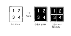
図25はNページ印刷と左右反転が同時に指定された場合の表示形式の考え方を示している。元データはページ全体にページ番号が表示されているようなデータ4ページを1枚の用紙に印刷する4ページ印刷を設定している。Nページ印刷には用紙上にNページのデータをどのように配置するかの配置順設定があり、この例は、まず左から右へNページのデータを配置し、右端まで並べたら一つ下の段へ移動するという配置順である。このデータを左右反転した場合も同様に用紙全体を反転した状態の▲1▼と配置順を保存してNページ毎に左右反転する▲2▼の配置順が考えられる。
【0133】
このように左右の概念を持つレイアウト設定と左右反転を組み合わせた場合には、複数の解釈が存在するので、結果を画面上でプレビューできることはユーザの意図した通りの印刷結果を得る為には有効な手段であり、また、プレビューアは実際の印刷結果と同じ形式となるように表示しなくてはならない。
【0134】
プレビューする方法には、中間データファイルから一つ一つ描画要素を取り出して画面に描画する方法や、一旦ビットマップなどの画像フォーマットに変換してからその画像データを表示する方法等がある。一般にプリンタは数百DPIの解像度を持つが、画面はその数分の1の解像度しか持たないので、1ページ分のデータ画像を作成してもプリンタに比べてデータ量が格段に小さくなる。プレビューアは実際に中間データを毎回画面上に描画するのではなく、一旦小画像データを作成しておいて、それを表示するようにすることで高速表示が可能となる場合が多い。印刷データが画像データや複雑なグラフィックデータを持っている場合には特に速度でもコンピュータのリソース使用量の面でも効果が大きい。本実施形態では、プレビューする際に、一旦画面の解像度に合わせた小さな画像データを作成してから、その画像データをコンピュータの画面に描画する方式の例を説明する。
【0135】
この場合、小画像データを作成する際に反転イメージを作るのではなく、反転前の画像データを作成し、画面に表示する際に小画像データを左右反転するという方法を取ってもよい。この場合の、左右反転のプレビュー方法について説明しているのが図26である。
【0136】
図26は、綴じ代と左右反転が同時に設定された場合には、図24の▲2▼の形式となる場合の例である。まず、綴じ代を左右逆に取った画像データを作成し、この画像データ全体を左右反転することで綴じ代位置を保存した左右反転画像を作成している。
【0137】
図31はこの処理の流れを説明したフローチャートの例である。まずステップ3110で中間ファイルから設定条件を読み込む。次にステップ3120に進みステップ3110で読み込んだ設定条件に左右反転が指定されているかどうかを判定する。左右反転が指定されていない場合には、ステップ3190に進み、通常通りにNページ印刷のNページ処理の画像処理を行い終了する。
【0138】
ステップ3120で左右反転が指定されている場合には、ステップ3130へと処理を進め、綴じ代の設定を調整する必要があるかどうかを判定する。綴じ代と左右反転で図24の▲1▼の方式の場合には綴じ代の設定を調整する必要がない。図24の▲2▼の場合には綴じ代位置を調整した画像イメージを作成するためにステップ3140へ処理を進め、綴じ代の設定を左右逆になるように調整する。
【0139】
次にステップ3150へ進みNページ印刷の配置順を調整する必要があるかの判定を行う。プレビューの画像データを用紙単位で作成し、かつ、配置順が図25の▲1▼の用に用紙全体で左右反転する場合には位置調整をする必要はない。その場合には、ステップ3170へと進む。ステップ3150で配置順を調整する必要があると判定された場合には、ステップ3160へ処理を進め配置順の設定をプレビュー用に調整する。そしてステップ3170で通常のNページ分の描画処理を行い、プレビュー用の画像を作成する。そして、実際に画面に描画する必要が生じたときにステップ3180に進み画像データを左右反転して表示する。
【0140】
画像データを用紙単位で作成するシステムの場合の例で処理を説明してしたが、プレビューの画像データを各論理ページ毎に作成しているような場合には、綴じ代や配置順の調整をする判定基準が異なってくる。また、綴じ代やNページ印刷の仕様が用紙全体を反転する仕様(図24,25の▲1▼)なのか、綴じ代や配置順を保存して印刷する仕様(図24、25の▲2▼)であるのかによってもステップ3130、ステップ3150の判定基準が異なる。
【0141】
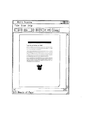
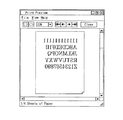
左右反転指定されたデータを実際にプレビューアで表示した例を図29、32に示す。図29は印刷設定に、単に左右反転が指定された場合のプレビューである。図32は印刷設定として4ページ印刷と左右反転が示された場合の例である。
【0142】
次に色反転の例を説明する。図23は色反転(ネガティブ)の概念図である。元のデータが白地に黒で「R」の文字が描画されている場合、黒字に白で「R」の文字が描画される。通常、プリンタには用紙送り機構の関係で紙の4辺の端には印刷することができない領域が存在するので、色反転して黒地に塗りつぶそうとしてもこの部分は白く残ってしまう。そのため、ネガティブイメージを正確に表示するには、この印刷できない領域を考慮してプレビューすることが必要である。
【0143】
図28は色反転のプレビュー方式について説明した図で、用紙全体を画像データとして作成している場合の例である。元のデータを仮想用紙の画像データに描画した後に、プリンタの紙送りで印刷できない四辺の部分を反転した画像データを作成する。このデータを画面上へ描画する際に、ラスタオペレーションで反転を指定して描画すると、一番右の様に、描画できない領域も表現された厳密なプレビュー表示が可能である。
【0144】
実際のプレビュー表示の例を図30に示す。図29のデータをさらに色反転した例であり、用紙の四辺の部分が反転されずに残っている状態がプレビューされている。
【0145】
色反転の場合は、印字可能領域全体を色反転するのが普通であるが、図27の▲2▼に示すように、Nページ印刷と色反転を組みあわせた場合に、用紙上に配置された各Nページの隙間部分を反転しないという場合も考えられる。綴じ代も同様に、反転せずに白く残す仕様も考えられる。プレビューの方式によるが、プレビュー方式がNページ印刷の各論理ページ毎にプレビュー画像を作成して、画面上の用紙表示上に配置する方式の場合、図27の▲2▼の様にページの隙間が反転できずに残ってしまうので、隙間部分を印字不可能領域と同様に反転しておく処理が必要となる。
【0146】
図33に色反転プレビューの処理の一例を説明したフローチャートを示す。まず、ステップ3310で通常の処理で中間ファイルから印刷設定条件を読み込む。次にステップ3320へ進み、ステップ3310で読み込んだ印刷設定条件に従い、用紙のプレビュー用画像データを作成する。ステップ3330へ進み、中間ファイル中の印刷設定に色反転が指定されているかどうかを判定する。ステップ3330で色反転が指定されている場合はステップ3340へ進み、プリンタの印字不可能領域の情報を取得する。
【0147】
本実施形態では、GDIの関数を呼び出すことでグラフィックエンジン202を経由してプリンタドライバ203からこの情報を取得することが可能である。次にステップ3350へ進み、ステップ3340で取得した印字不可能領域を反転する。さらにステップ3360へ進み、画像を反転表示する。ステップ3330で色反転が指定されていないと判定された場合には、ステップ3370に進み、通常の画面への表示処理を行なう。
【0148】
この例では、色反転されていない画像データを作成し、実際に画面上にプレビューする際に反転していたが、色反転後の画像データを作成して、画面上には通常の描画を行う方法でも同様である。
【0149】
<他の実施形態>
なお、本発明にかかる実施形態は、複数の機器(例えばホストコンピュータ、インタフェイス機器、リーダ、プリンタなど)から構成されるシステムに適用しても、一つの機器からなる装置(複写機、プリンタ、ファクシミリ装置など)に適用してもよい。
また、本発明の目的は前述した実施形態の機能を実現するソフトウェアのプログラムコードを記憶した記憶媒体を、システムあるいは装置のコンピュータ(またはCPUやMPU)が記憶媒体に格納されたプログラムコードを読出し実行することによっても、達成される。
【0150】
この場合、記憶媒体から読み出されたプログラムコード自体が前述した実施形態の機能を実現することになり、そのプログラムコードを記憶した記憶媒体は本発明を構成することになる。
【0151】
プログラムコードを供給するための記憶媒体としては、例えば、フロッピーディスク、ハードディスク、光ディスク、光磁気ディスク、CD?ROM、CD?R、磁気テープ、不揮発性のメモリカード、ROMなどを用いることができる。
【0152】
また、コンピュータが読み出したプログラムコードを実行することにより、前述した実施形態の機能が実現されるだけでなく、そのプログラムコードの指示に基づき、コンピュータ上で稼動しているOS(オペレーティングシステム)などが実際の処理の一部または全部を行い、その処理によって前述した実施形態の機能が実現される場合も含まれる。
【0153】
更に、記憶媒体から読出されたプログラムコードが、コンピュータに挿入された機能拡張ボードやコンピュータに接続された機能拡張ユニットに備わるメモリに書き込まれた後、そのプログラムコードの指示に基づき、その機能拡張ボードや機能拡張ユニットに備わるCPUなどが実際の処理の一部または全部を行い、その処理によって前述した実施形態の機能が実現される場合も含まれる。
【0154】
また、本発明の目的は、前述した実施形態の機能を実現するソフトウェアのプログラムコードを、システムあるいは装置のコンピュータ(またはCPUやMPU)にインストールし、そのインストールされたプログラムコードを読み出し実行することによっても、達成される。
【0155】
この場合、インターネットのダウンロードサービス等でダウンロードされ、インストールされたプログラムコード自体が前述した実施形態の機能を実現することになり、そのプログラムコード自体は本発明を構成することになる。
【0156】
【発明の効果】
以上説明したように、本発明によれば、左右反転といった特殊なプリンタの効果もホストコンピュータ上でプレビュー可能となる。
【0157】
また、本発明によれば、色反転といった特殊なプリンタの効果もホストコンピュータ上でプレビュー可能となる。
【図面の簡単な説明】
【図1】本発明の一実施形態を示す印刷制御装置の構成を説明するブロック図である。
【図2】プリンタが接続されたホストコンピュータの典型的なプリントシステムの構成を示すブロック図である。
【図3】アプリケーションからの印刷命令をプリンタ制御コマンドに変換する前に、一旦中間コードスプールするプリントシステムの構成を示すブロック図である。
【図4】本発明におけるプリンタについて説明した図である。
【図5】スプーラ302における処理を示したフローチャートである。
【図6】スプールファイルマネージャ304における印刷制御について示したフローチャートである。
【図7】デスプーラ305における処理を示したフローチャートである。
【図8】印刷設定画面の一例である。
【図9】印刷スプール設定画面の一例である。
【図10】スプールファイルマネージャ304が生成する印刷可能となった物理ページを構成する情報を保存しているジョブ出力用設定ファイルの例を示す図である。
【図11】ジョブ設定情報の一例を示す図である。
【図12】物理ページ情報の一例を図である。
【図13】物理ページ設定情報の一例を示す図である。
【図14】スプールファイルマネージャ304からデスプーラ305に対して物理ページの印刷要求を行う際に渡すデータ形式の一例を示した図である。
【図15】設定変更エディタ307における設定変更処理について示したフローチャートである。
【図16】スプールファイルマネージャ304でスプールされている印刷ジョブ一覧を表示する画面の一例である。
【図17】プレビューア306の画面の一例である。
【図18】設定変更エディタ307の画面の一例である。
【図19】ネガティブ印刷、ミラー印刷を設定する印刷設定画面の一例である。
【図20】図19の印刷設定画面において、色反転(ネガティブ)を設定した場合の一例である。
【図21】図19の印刷設定画面において、左右反転(ミラー)を設定した場合の一例である。
【図22】左右反転(ミラー)の表示例を示す図である。
【図23】色反転(ネガティブ)の表示例を示す図である。
【図24】左右反転と綴じ代の組み合わせを説明した図である。
【図25】左右反転とNページ印刷の組み合わせを説明した図である。
【図26】綴じ代と左右反転を組み合わせたプレビューの表示処理の一例を説明した図である。
【図27】色反転とNページ印刷の組み合わせを示した例である。
【図28】描画できない領域を考慮した色反転プレビューの表示処理の一例である。
【図29】左右反転のプレビュー表示の一例である。
【図30】色反転のプレビュー表示の一例である。
【図31】左右反転時の処理の一例を示したフローチャートである。
【図32】左右反転のプレビュー表示の一例である。
【図33】色反転のプレビュー表示処理の例を説明したフローチャートである。
【符号の説明】
1 CPU
2 RAM
3 ROM
4 システムバス
12 CPU
13 ROM
19 RAM
3000 ホストコンピュータ
1500 プリンタ[0001]
BACKGROUND OF THE INVENTION
The present invention relates to an information processing apparatus and method for generating print data, and a storage medium, and more particularly to an information processing apparatus and information processing method for controlling to display a preview considering print settings of print data generated by an application. And a storage medium storing a computer-readable program for executing the information processing method.
[0002]
[Prior art]
When printing a document (document data) generated by an application on a client computer, in recent years, it has become possible to print by specifying various layouts using a high-function printer driver. As the layout setting becomes more complicated, confirming (previewing) the output result on the host screen is an effective way to quickly obtain the desired print result without waste.
[0003]
In general, each application provides a function for previewing on the screen of the client computer (host computer) before printing. In this case, a preview of the result of applying the layout function of the application is displayed on the screen. You can check above.
[0004]
However, in the conventional method, the layout function provided by the printing apparatus such as a printer and the printer driver for the printer cannot be confirmed. In particular, the special functions provided in the printer main body could not be previewed. For example, there is a problem that it is not possible to preview functions such as color reversal (negative) printing and right / left reversal (mirror) printing of a PS printer.
[0005]
[Problems to be solved by the invention]
The present invention has been made to solve the above-described problems. A special function setting of the printer main body is detected from the print settings, and the function of the printer is simulated on the client computer in accordance with the setting to be previewed. It can be displayed.
[0006]
[Means for Solving the Problems]
An information processing apparatus and method and a storage medium of the present invention that achieve the above object are characterized by having the following configuration.
[0007]
That is, an information processing apparatus according to the present invention is an information processing apparatus that generates a print job to be printed by a printing apparatus,
The position of the binding margin with respect to the page and the mirror image printing attribute that flips the page horizontallyAs processing conditions for print dataSetting means for setting;
A designation means for designating display of a preview image for confirming the output result;
Intermediate data conversion means for converting the print data output from the application into an intermediate code format, and storing the converted intermediate code format data and the processing conditions of the print data;
When it is designated by the designation means to display the preview image, the setting content by the setting means,AboveOutput from the applicationAbovePrint dataData in the intermediate code format converted fromAnd a preview display control means for holding a position of the binding margin at the position set by the setting means and displaying a preview image obtained by horizontally inverting the image based on the print data;,
Job display means for generating a print job based on the data in the intermediate code format stored by the intermediate data conversion means after the preview display control means displays the preview image;
The intermediate code format data is used for both generation of the print job and display of the preview image.It is characterized by that.
[0008]
An information processing method according to the present invention is an information processing method executed in an information processing apparatus that generates a print job to be printed by a printing apparatus,
The position of the binding margin with respect to the page and the mirror image printing attribute that flips the page horizontallyAs processing conditions for print dataA setting process to set;
A designation process for designating that a preview image for confirming the output result is displayed;
An intermediate data conversion step of converting the print data output from the application into an intermediate code format, and storing the converted intermediate code format data and processing conditions of the print data;
When it is designated to display the preview image in the designation step, the setting content set in the setting step;AboveOutput from the applicationAbovePrint dataData in the intermediate code format converted fromAnd a preview display control step of holding a binding margin position at the position set in the setting step and displaying a preview image obtained by horizontally inverting the image based on the print data;,
A job generation step of generating a print job based on the data in the intermediate code format stored by the intermediate data conversion step after the preview image is displayed by the preview display control step;
The intermediate code format data is used for both generation of the print job and display of the preview image.It is characterized by that.
[0010]
DETAILED DESCRIPTION OF THE INVENTION
<First Embodiment>
Hereinafter, an embodiment suitable for applying the present invention will be described.
[0011]
FIG. 1 is a block diagram illustrating the configuration of a printer control system according to an embodiment of the present invention. As long as the function of the present invention is executed, a system in which processing is performed by being connected via a network such as a LAN or WAN, whether it is a single device or a system composed of a plurality of devices. Even so, the present invention can be applied.
[0012]
In the figure, the
[0013]
A keyboard controller (KBC) 5 controls key input from a
[0014]
For example, the
[0015]
The
[0016]
The
[0017]
The
[0018]
FIG. 2 is a configuration diagram of typical print processing in a host computer to which a printing apparatus such as a printer is directly connected or connected via a network. The
[0019]
The
[0020]
The
[0021]
In addition to the printing system comprising the
[0022]
FIG. 3 is an extension of the system shown in FIG. 2 and has a configuration in which a spool file 303 including an intermediate code is temporarily generated when a print command is sent from the
[0023]
In the system shown in FIG. 3, the contents of the spool file 303 can be processed. As a result, it is possible to realize functions that the application does not have, such as enlargement / reduction or printing by reducing a plurality of pages into one page with respect to print data from the application.
[0024]
For these purposes, the system of FIG. 2 has been extended to spool with intermediate code data as shown in FIG. In order to process print data, settings are made from a window provided by the
[0025]
Details of FIG. 3 will be described below. As shown in the figure, in this expanded processing method, the
[0026]
The
[0027]
The spool file 303 is generated as a file on the
[0028]
When the
[0029]
The
[0030]
If the print command (DDI function) received by the
[0031]
The
[0032]
Further, FIG. 3 shows a configuration example in which a
[0033]
In order to perform print preview, print setting change, and combination of a plurality of jobs, first, the user selects “Store” in a pull-down menu that is a means for performing “designation of output destination” in the printer driver properties shown in FIG. Must be specified. If you want to see only the preview, you can select "Preview" as the output destination.
[0034]
In this way, the contents set in the printer driver properties are stored as a setting file in a structure provided by the OS (called DEVMODE in the Windows OS). The structure includes, for example, a setting for whether to store in the
[0035]
FIG. 16 shows an example in which four jobs are spooled, and a job can be operated by pressing a menu bar or a menu icon immediately below it. The number of operations on the menu bar and menu icon is the same. The operation type is “Print” with the job selected, “Save and Print” to leave the spool file of the intermediate code as it is, and “Job Save” to see the output preview of the job considering the print settings. "Preview", "Delete" to delete the intermediate code spool file, "Duplicate" to generate a copy of the intermediate code spool file, "Combine" to combine multiple intermediate code spool file jobs into one job “Divide” to divide the combined job into a plurality of original jobs, “job editing” to change the print settings (layout settings, finishing settings, etc.) of a single job or a combined job, Move to the top ”, move the print order of a job forward by one,“ move up ”, and set the print order of a job by one There are eleven operations more "move down one", "last movement" of the printing order of a job to last.
[0036]
When a preview of a single job or a combined job is designated on the spool file manager window screen (FIG. 16), the
[0037]
The
[0038]
The
[0039]
Note that the preview function of application software such as conventional document creation is drawn based on the page settings in the application, so the print settings in the printer driver are not reflected and the actual printout is performed. It was not possible to make the user recognize the preview.
[0040]
By performing the preview process as described above, a large preview of the print processing settings included in the spool file 303 is displayed on the screen by the
[0041]
If the user performs printing in accordance with the contents displayed by the
[0042]
Next, setting change using the setting
[0043]
As a realization method, it is possible to set a job for which “Store” is designated in FIG. The
[0044]
The setting
[0045]
This setting
[0046]
Here, it is possible to change and modify the contents of the processing settings included in the job setting file stored in the spool file 303. At this time, items that can be set in the
[0047]
The change item changed here is authenticated in accordance with the authentication request on the setting
[0048]
If the user performs printing according to the setting change contents as in the confirmation by the
[0049]
On the spool file manager window screen (FIG. 16), it is possible to specify that a plurality of print jobs are combined and printed as one print job. Similarly to the preview and setting change, this is also premised on a job in which the output destination is specified as “Store” in the printer driver properties shown in FIG.
[0050]
When the user combines print jobs, first, the
[0051]
Here, when a plurality of jobs are selected and “join” is specified, the setting
[0052]
The setting
[0053]
Here, each job can be displayed with the processing settings before combining, or can be displayed after being changed and corrected to a unified processing setting as a combined job. At this time, items that can be set in the
[0054]
As described above, the combined job and the changed change item are authenticated in accordance with the authentication request on the setting
[0055]
If the user performs printing according to the setting change contents as in the confirmation by the
[0056]
FIG. 4 is a cross-sectional view of a color laser printer having a double-sided printing function, which is an example of the
[0057]
This printer forms an electrostatic latent image by scanning the
[0058]
The
[0059]
The developing unit includes three
[0060]
The black developing unit 21B is detachably attached to the printer main body, and the
[0061]
The sleep 21BS of the black developing device 21B is arranged with a minute interval of about 300 μm, for example, with respect to the
[0062]
The three
[0063]
At the time of color image formation, the developing
[0064]
The
[0065]
The
[0066]
As shown by a solid line in FIG. 4, the
[0067]
The fixing
[0068]
The
[0069]
The cleaning unit cleans the toner remaining on the
[0070]
The transfer material (recording paper) 2 to be printed is taken out from the
[0071]
The recording sheet guided to the duplex unit is once sent to the lower part of the tray 1 (conveying path indicated by a two-dot chain line) by the conveying
[0072]
FIG. 5 is a flowchart showing the process of the page unit storage step in the generation of the spool file 303 in the
[0073]
First, in step 501, the
[0074]
In step 502, the
[0075]
Subsequently, in step 504, the
[0076]
On the other hand, if it is determined in step 502 that the request is not a job start request, the process proceeds to step 506.
[0077]
In step 506, the
[0078]
If it is determined in step 507 that the received print request is not a page break, the process advances to step 509, and the
[0079]
Next, in step 510, in order to store the print request in the spool file 303, the
[0080]
Further, the
[0081]
On the other hand, if it is determined in step 506 that the print request from the application is the end of the job, all the print requests from the application are complete, so the process proceeds to step 512 and the print processing progress to the
[0082]
FIG. 6 is a flowchart showing details of control in the
[0083]
In step 601, the
[0084]
In step 602, the
[0085]
On the other hand, if the print start notification is not received from the
[0086]
In the subsequent step 606, it is determined whether printing of one physical page can be started for the n logical pages for which spooling has been completed at this time. If printing is possible, the process advances to step 607 to determine the physical page number from the logical number assigned to one physical page to be printed.
[0087]
For the calculation of the physical page, for example, when the processing setting is such that four logical pages are arranged on one physical page, the first physical page can be printed when the fourth logical page is spooled, and the first physical page is printed. It becomes a page. Subsequently, the second physical page can be printed when the eighth logical page is spooled.
[0088]
Even if the total number of logical pages is not a multiple of the number of logical pages allocated to one physical page, the logical page to be allocated to one physical page can be determined by the spool end notification in step 512.
[0089]
In step 608, in the format shown in FIG. 10, the logical page number constituting the printable physical page and information such as the physical page number are stored in the job output setting file (file including physical page information). ) And the
[0090]
On the other hand, if the progress notification is not a print end notification of one logical page from the
[0091]
On the other hand, if it is determined that the printing for the processing setting has not yet been completed, the process proceeds to 606 described above. The
[0092]
Further, when the spool progress is faster than the despooling progress or when despooling is started after the spooling of all pages is completed, in step 608, notification of page printing is possible for each physical page. In accordance with the progress on the despooling side, it is possible to save the number of notifications by using notification contents indicating that a plurality of physical pages or all physical pages can be printed.
[0093]
If it is determined in step 610 that the notification is not a print end notification for one physical page from the
[0094]
FIG. 7 is a flowchart showing details of the print data generation process in the
[0095]
In response to a print request from the
[0096]
In the generation of print data, first, in step 701, a notification from the
[0097]
On the other hand, if it is not a job end notification in step 702, the process proceeds to step 704, and it is determined whether or not a print start request for one physical page in step 608 is notified. If it is not determined to be a start request in step 704, the process proceeds to step 710, other error processing is performed, and the process returns to step 701 to wait for the next notification.
[0098]
On the other hand, if it is determined in step 704 that the print start request is for one physical page, the process proceeds to step 705, and the
[0099]
If all the physical pages have been processed, the process proceeds to step 707 to determine whether the end flag is set in step 703 described above. If the end flag is set, it is considered that the printing of the job has been completed, the processing end notification of the
[0100]
On the other hand, if it is determined in step 706 that there are still printable physical pages, the process proceeds to step 708, and the
[0101]
The above is the flow of print processing using the
[0102]
Here, in print processing using the
[0103]
FIG. 10 shows an example of a job output setting file that stores information constituting the printable physical page generated by the
[0104]
A
[0105]
The
[0106]
A
[0107]
FIG. 11 is an example of job setting information illustrated in the
[0108]
The
[0109]
A
[0110]
FIG. 12 shows an example of physical page information shown in the
[0111]
FIG. 13 shows an example of physical
[0112]
A
[0113]
In other words, the color page rotates four times if the intermediate transfer member (intermediate transfer drum, intermediate transfer belt) or the transfer member (transfer drum, transfer belt) is YMCK for the number of device colors, and the monochrome page rotates only one time for black. This makes it possible to control the transfer. A
[0114]
FIG. 14 shows an example of logical page information indicated by 1204. A
[0115]
A
[0116]
The job output setting file is configured as described above. The job setting file is almost the same as the print format (single side, double side, bookbinding printing), print layout (Nup, poster printing), additional information (watermark, date, user name addition), number of copies, and paper size information. Are arranged as a job, and each physical page is composed of a logical page arrangement order, front or back of double-sided printing, color mode, and the like.
[0117]
Further, FIG. 3 shows an example in which a
[0118]
FIG. 15 is a flowchart showing details of the job setting change processing process in the setting
[0119]
First, in
[0120]
In step 1503, a dialog with the user is performed on the user interface as shown in FIG. 18, and the setting contents are changed by specifying the menu described above. This step may be a batch format that changes according to the contents of the setting change written in a file or the like instead of the interactive format. Next, proceeding to step 1504, in
[0121]
If it is determined in step 1505 that there is no change, the spool file manager is notified that there was no change, and the process ends. In this way, a new job output setting file is generated. When the “OK” button is selected on the user interface screen in FIG. 18, the new job output setting file becomes valid, and the old job output setting file is displayed. The file is deleted. Also, instead of changing from the job output setting file, the job setting file of a single job is stored without being deleted.
[0122]
When the “return to initial state” button (1801) is selected on the screen of FIG. 18, the new job output setting file is deleted, and the old job output setting file becomes valid and is reflected in the display. In this embodiment, the setting
[0123]
FIG. 3 further illustrates an extended system that combines a plurality of print jobs and prints them as a single print job. The extension for despooling and previewing the combined job will be described.
[0124]
Normally, the intermediate format spool file 303 is created for each job. In the case of a single job, since the intermediate code of each logical page in the job file to be processed is read in order and processed, the logical page ID in the
[0125]
In this embodiment, the spool file is specified by adding an ID for identifying the spool file to the logical page ID. In this case, only the field 1401 (FIG. 14) is the main change. This is because, if the spool file can be identified, the page portion can be read by the same logic as the processing of a single job. In addition, when the spool file is stored in the form of a separate file for each logical page, there is a mounting form in which the logical page file name is used as the logical page ID of the
FIG. 22 is a conceptual diagram of left-right reversal (mirror). When the original data is full of paper and the character “R” is drawn, when the left / right reverse is designated, the character “R” is printed in the reverse right and left as if it was reflected in the mirror.
[0126]
When performing print settings for left / right reversal (mirror) and color reversal (negative), a dialog for inputting print settings as shown in FIG. 19 is displayed, and the print settings input by the dialog pattern are displayed in the spooler 303 by the printer driver. Passed. The setting input dialog shown in FIG. 19 includes setting items for setting left / right reversal and color reversal such as 1901.
[0127]
FIG. 20 and FIG. 21 show display examples of the setting input dialog when color inversion is specified in the setting input dialog of FIG. 19 and when left / right inversion is specified, respectively. Although not shown in the example, it is also possible to specify color inversion and left-right inversion simultaneously.
[0128]
When left / right inversion is specified, attention must be paid to the display result when it is specified at the same time as the setting item having the left / right concept in other layout settings.
[0129]
FIG. 24 shows the concept of the display format when binding margin and left / right reversal are specified at the same time. The original data has a binding margin (shown by a gray rectangle) on the left side of the paper. In this case, there are two possible results of left-right inversion.
[0130]
In the first case, as shown in (1), the binding margin is reversed left and right together as if the entire sheet is reflected in the mirror. In this case, the paper is reversed from the whole paper, but if the binding is actually attempted to the binder, the binding margin comes to the right and the left binding cannot be performed. It is desirable to reverse the entire sheet in this way when making a composition.
[0131]
The second is a case where the direction of the binding margin is saved and only the drawing data portion is inverted as shown in (2). When using reversal as a special effect, it is better to preserve the binding direction.
[0132]
FIG. 25 shows the concept of the display format when N-page printing and left / right inversion are specified at the same time. The original data is set to four-page printing in which four pages of data whose page numbers are displayed on the entire page are printed on one sheet. In N-page printing, there is an arrangement order setting for how N-page data is arranged on the paper. In this example, N-page data is arranged from left to right first, and then arranged to the right, then one down. The arrangement order is to move to the next stage. Similarly, when the data is reversed left and right, the arrangement order (1) where the entire sheet is reversed and the arrangement order (2) where the arrangement order is stored and reversed left and right for every N pages can be considered.
[0133]
In this way, when layout settings with left and right concepts and left / right inversion are combined, there are multiple interpretations, so previewing the results on the screen is effective for obtaining the print results as intended by the user. In addition, the previewer must display the same format as the actual print result.
[0134]
As a preview method, there are a method of taking out drawing elements one by one from the intermediate data file and drawing them on the screen, a method of once converting the image data into an image format such as a bitmap, and displaying the image data. In general, a printer has a resolution of several hundred DPI, but the screen has only a fraction of that resolution, so even if a data image for one page is created, the amount of data is significantly smaller than that of a printer. In many cases, the previewer does not actually draw the intermediate data on the screen every time, but once the small image data is created and displayed, it can be displayed at high speed. When the print data has image data or complex graphic data, the effect is great both in terms of speed and computer resource usage. In the present embodiment, an example of a method in which, when previewing, small image data that matches the screen resolution is once created and then the image data is drawn on the computer screen will be described.
[0135]
In this case, instead of creating a reversed image when creating small image data, a method may be employed in which image data before inversion is created and the small image data is reversed left and right when displayed on the screen. FIG. 26 explains the preview method of left-right reversal in this case.
[0136]
FIG. 26 shows an example of the case of (2) in FIG. 24 when the binding margin and the left / right reversal are set at the same time. First, image data in which the binding margin is reversed left and right is created, and a left-right inverted image in which the binding margin position is stored is created by horizontally flipping the entire image data.
[0137]
FIG. 31 is an example of a flowchart illustrating the flow of this process. First, in step 3110, setting conditions are read from the intermediate file. Next, proceeding to step 3120, it is determined whether or not left / right inversion is specified in the setting condition read at step 3110. If left-right reversal is not designated, the process proceeds to step 3190, where image processing for N-page processing for N-page printing is performed as usual, and the process ends.
[0138]
If left / right reversal is specified in step 3120, the process proceeds to step 3130 to determine whether it is necessary to adjust the binding margin setting. In the case of the method (1) in FIG. 24 with the binding margin and left / right reversal, it is not necessary to adjust the binding margin setting. In the case of (2) in FIG. 24, the process proceeds to step 3140 in order to create an image with the binding margin position adjusted, and the binding margin setting is adjusted so as to be reversed left and right.
[0139]
Next, the process proceeds to step 3150 to determine whether it is necessary to adjust the arrangement order of N-page printing. If the preview image data is created in units of paper and the arrangement order is reversed horizontally for the whole paper as shown in (1) in FIG. 25, there is no need to adjust the position. In that case, go to Step 3170. If it is determined in step 3150 that the arrangement order needs to be adjusted, the process proceeds to step 3160 to adjust the arrangement order setting for preview. In step 3170, a normal N-page drawing process is performed to create a preview image. Then, when it becomes necessary to actually draw on the screen, the process proceeds to step 3180, and the image data is displayed horizontally reversed.
[0140]
The processing has been explained with an example of a system that creates image data in units of paper. However, when preview image data is created for each logical page, adjustment of binding margin and arrangement order is performed. The judgment criteria to be used are different. Also, whether the binding margin and N-page printing specifications are specifications that invert the entire sheet (1) in FIGS. 24 and 25, or the specifications that save and print the binding margins and arrangement order (2 in FIGS. 24 and 25). The determination criteria of step 3130 and step 3150 also differ depending on whether or not it is.
[0141]
29 and 32 show examples in which the data designated to be reversed horizontally is actually displayed in the previewer. FIG. 29 is a preview when the horizontal setting is simply designated as the print setting. FIG. 32 shows an example in which four-page printing and left / right inversion are shown as print settings.
[0142]
Next, an example of color inversion will be described. FIG. 23 is a conceptual diagram of color inversion (negative). If the original data is black and the letter “R” is drawn on a white background, the letter “R” is drawn in black on the white. Normally, printers have areas that cannot be printed at the edges of the four sides of the paper because of the paper feed mechanism, so even if the color is reversed and painted on a black background, this portion remains white. Therefore, in order to accurately display a negative image, it is necessary to preview in consideration of this unprintable area.
[0143]
FIG. 28 is a diagram for explaining the color inversion preview method, and shows an example in which the entire sheet is created as image data. After drawing the original data on the image data of the virtual paper, image data is created by inverting the four sides that cannot be printed by the paper feed of the printer. When this data is drawn on the screen, if the reverse is designated by the raster operation and the drawing is carried out, a strict preview display can be made in which the area that cannot be drawn is represented as shown on the rightmost side.
[0144]
An example of an actual preview display is shown in FIG. This is an example in which the data of FIG. 29 is further color-inverted, and a preview is shown of the state where the four sides of the sheet remain without being inverted.
[0145]
In the case of color reversal, it is normal to reverse the color of the entire printable area. However, as shown in (2) in FIG. 27, when N-page printing and color reversal are combined, they are placed on the paper. It is also conceivable that the gap between each N pages is not reversed. Similarly, the binding margin can be left white without being inverted. Depending on the preview method, the preview method creates a preview image for each logical page of N pages and places it on the paper display on the screen. As shown in (2) in FIG. Therefore, a process for inverting the gap portion in the same manner as the non-printable area is necessary.
[0146]
FIG. 33 is a flowchart illustrating an example of color inversion preview processing. First, in step 3310, print setting conditions are read from the intermediate file by normal processing. In step 3320, paper preview image data is created in accordance with the print setting conditions read in step 3310. Proceeding to step 3330, it is determined whether color inversion is designated in the print settings in the intermediate file. If color inversion is designated in step 3330, the process proceeds to step 3340, and information on the unprintable area of the printer is acquired.
[0147]
In this embodiment, this information can be acquired from the
[0148]
In this example, image data that is not color-reversed is created and reversed when actually previewing on the screen, but the image data after color reversal is created and normal drawing is performed on the screen. The same applies to the method.
[0149]
<Other embodiments>
Note that the embodiment according to the present invention can be applied to a system composed of a plurality of devices (for example, a host computer, an interface device, a reader, a printer, etc.), but an apparatus (copier, printer, The present invention may be applied to a facsimile machine or the like.
Another object of the present invention is to read and execute the program code stored in the storage medium by the computer (or CPU or MPU) of the system or apparatus, which stores the program code of the software that implements the functions of the above-described embodiments. Is also achieved.
[0150]
In this case, the program code itself read from the storage medium realizes the functions of the above-described embodiments, and the storage medium storing the program code constitutes the present invention.
[0151]
As a storage medium for supplying the program code, for example, a floppy disk, a hard disk, an optical disk, a magneto-optical disk, a CD-ROM, a CD-R, a magnetic tape, a nonvolatile memory card, a ROM, or the like can be used.
[0152]
Further, by executing the program code read by the computer, not only the functions of the above-described embodiments are realized, but also an OS (operating system) operating on the computer based on the instruction of the program code. A case where part or all of actual processing is performed and the functions of the above-described embodiments are realized by the processing is also included.
[0153]
Furthermore, after the program code read from the storage medium is written into a memory provided in a function expansion board inserted into the computer or a function expansion unit connected to the computer, the function expansion board is based on the instruction of the program code. The CPU included in the function expansion unit performs part or all of the actual processing, and the functions of the above-described embodiments are realized by the processing.
[0154]
In addition, the object of the present invention is to install a program code of software that realizes the functions of the above-described embodiments in a computer (or CPU or MPU) of a system or apparatus, and read and execute the installed program code. Is also achieved.
[0155]
In this case, the program code itself downloaded and installed by the Internet download service or the like realizes the functions of the above-described embodiment, and the program code itself constitutes the present invention.
[0156]
【The invention's effect】
As described above, according to the present invention, special printer effects such as left-right reversal can be previewed on the host computer.
[0157]
In addition, according to the present invention, special printer effects such as color reversal can be previewed on the host computer.
[Brief description of the drawings]
FIG. 1 is a block diagram illustrating a configuration of a print control apparatus according to an embodiment of the present invention.
FIG. 2 is a block diagram illustrating a configuration of a typical print system of a host computer to which a printer is connected.
FIG. 3 is a block diagram illustrating a configuration of a printing system that temporarily spools an intermediate code before converting a print command from an application into a printer control command.
FIG. 4 is a diagram illustrating a printer according to the present invention.
FIG. 5 is a flowchart showing processing in the
FIG. 6 is a flowchart showing print control in the spool file manager.
FIG. 7 is a flowchart showing processing in the
FIG. 8 is an example of a print setting screen.
FIG. 9 is an example of a print spool setting screen.
FIG. 10 is a diagram illustrating an example of a job output setting file that stores information constituting a printable physical page generated by the spool file manager.
FIG. 11 is a diagram illustrating an example of job setting information.
FIG. 12 is a diagram illustrating an example of physical page information.
FIG. 13 is a diagram illustrating an example of physical page setting information.
FIG. 14 is a diagram illustrating an example of a data format that is passed when the
15 is a flowchart showing setting change processing in a setting
FIG. 16 is an example of a screen that displays a list of print jobs spooled by the spool file manager.
FIG. 17 is an example of a screen of the
18 is an example of a screen of a setting
FIG. 19 is an example of a print setting screen for setting negative printing and mirror printing.
20 is an example when color inversion (negative) is set on the print setting screen of FIG. 19;
FIG. 21 is an example when left-right reversal (mirror) is set on the print setting screen of FIG. 19;
FIG. 22 is a diagram showing a display example of left-right reversal (mirror).
FIG. 23 is a diagram illustrating a display example of color inversion (negative).
FIG. 24 is a diagram illustrating a combination of left / right reversal and binding margin.
FIG. 25 is a diagram illustrating a combination of left-right reversal and N-page printing.
FIG. 26 is a diagram illustrating an example of a preview display process that combines binding margin and left / right reversal.
FIG. 27 is an example showing a combination of color reversal and N-page printing.
FIG. 28 is an example of display processing of a color inversion preview in consideration of an area that cannot be drawn.
FIG. 29 is an example of a horizontally reversed preview display.
FIG. 30 is an example of a color inversion preview display.
FIG. 31 is a flowchart showing an example of processing at the time of horizontal reversal.
FIG. 32 is an example of a horizontally reversed preview display.
FIG. 33 is a flowchart illustrating an example of color inversion preview display processing.
[Explanation of symbols]
1 CPU
2 RAM
3 ROM
4 System bus
12 CPU
13 ROM
19 RAM
3000 host computer
1500 printer
Claims (11)
ページに対する綴じ代の位置、および、ページを左右反転する鏡像印刷属性を印刷データの処理条件として設定する設定手段と、
出力結果を確認するためのプレビュー画像を表示することを指定する指定手段と、
アプリケーションより出力された印刷データを中間コード形式に変換し、該変換された中間コード形式のデータと、前記印刷データの処理条件とを保存する中間データ変換手段と、
前記指定手段によって前記プレビュー画像を表示することが指定された場合、前記設定手段による設定内容と、前記アプリケーションから出力された前記印刷データから変換された前記中間コード形式のデータとに基づいて、前記綴じ代の位置を前記設定手段によって設定された位置に保持し、前記印刷データに基づく画像を左右反転させたプレビュー画像を表示するプレビュー表示制御手段と、
前記プレビュー表示制御手段が前記プレビュー画像を表示した後で、前記中間データ変換手段により保存された前記中間コード形式のデータに基づいて、印刷ジョブを生成するジョブ生成手段とを備え、
前記中間コード形式のデータは、前記印刷ジョブの生成と前記プレビュー画像の表示との両者に用いられることを特徴とする情報処理装置。An information processing apparatus that generates a print job to be printed by a printing apparatus,
A setting means for setting a binding margin position with respect to the page and a mirror image printing attribute for horizontally flipping the page as print data processing conditions ;
A designation means for designating display of a preview image for confirming the output result;
Intermediate data conversion means for converting the print data output from the application into an intermediate code format, and storing the converted intermediate code format data and the processing conditions of the print data;
When it is designated to display the preview image by the designation unit, the setting contents by the setting means, based on the data of the converted the intermediate code format from the print data output from the application, the Preview display control means for holding a binding margin position at the position set by the setting means and displaying a preview image obtained by horizontally inverting the image based on the print data ;
Job display means for generating a print job based on the data in the intermediate code format stored by the intermediate data conversion means after the preview display control means displays the preview image;
The intermediate code format data is used for both generation of the print job and display of the preview image .
前記編集手段は、複数の中間コード形式の印刷データが保存されている場合に、該複数の中間コード形式の印刷データを結合して一つの結合ジョブを生成することを特徴とする請求項1に記載の情報処理装置。An editing unit that edits the setting condition of the print data stored in the intermediate data conversion unit and converted into the intermediate code format;
Said editing means, when the print data of a plurality of intermediate code format is stored, in claim 1, characterized in that to generate one combined job by combining print data in the intermediate code format of said plurality of The information processing apparatus described.
前記プレビュー表示制御手段は、前記綴じ代の位置として設定された位置に対して左右逆向きの位置に当該綴じ代が設けられた画像を生成し、
当該生成された画像を左右反転することで、前記プレビュー画像を表示することを特徴とする請求項1に記載の情報処理装置。When the setting unit has set the binding margin position with respect to the page and the mirror image printing attribute for flipping the page horizontally,
The preview display control means generates an image in which the binding margin is provided at a position opposite to the left and right with respect to the position set as the binding margin position.
The information processing apparatus according to claim 1, wherein the preview image is displayed by horizontally flipping the generated image.
ページに対する綴じ代の位置、および、ページを左右反転する鏡像印刷属性を印刷データの処理条件として設定する設定工程と、
出力結果を確認するためのプレビュー画像を表示することを指定する指定工程と、
アプリケーションより出力された印刷データを中間コード形式に変換し、該変換された中間コード形式のデータと、前記印刷データの処理条件とを保存する中間データ変換工程と、
前記指定工程において前記プレビュー画像を表示することが指定された場合、前記設定工程において設定された設定内容と、前記アプリケーションから出力された前記印刷データから変換された前記中間コード形式のデータとに基づいて、前記綴じ代の位置を前記設定工程で設定された位置に保持し、前記印刷データに基づく画像を左右反転させたプレビュー画像を表示するプレビュー表示制御工程と、
前記プレビュー表示制御工程により前記プレビュー画像が表示された後で、前記中間データ変換工程により保存された前記中間コード形式のデータに基づいて、印刷ジョブを生成するジョブ生成工程とを備え、
前記中間コード形式のデータは、前記印刷ジョブの生成と前記プレビュー画像の表示との両者に用いられることを特徴とする情報処理方法。An information processing method executed in an information processing apparatus that generates a print job to be printed by a printing apparatus,
A setting step for setting the position of the binding margin with respect to the page and the mirror image printing attribute for horizontally flipping the page as the processing condition of the print data ;
A designation process for designating that a preview image for confirming the output result is displayed;
An intermediate data conversion step of converting the print data output from the application into an intermediate code format, and storing the converted intermediate code format data and processing conditions of the print data;
When it is designated for displaying the preview image in the designation step, on the basis of the setting content set in the setting step, the data of the converted the intermediate code format from the print data output from the application A preview display control step of holding the binding margin position at the position set in the setting step and displaying a preview image obtained by horizontally inverting the image based on the print data ;
A job generation step of generating a print job based on the data in the intermediate code format stored by the intermediate data conversion step after the preview image is displayed by the preview display control step;
The intermediate code format data is used for both generation of the print job and display of the preview image .
前記編集工程は、複数の中間コード形式の印刷データが保存されている場合に、該複数の中間コード形式の印刷データを結合して一つの結合ジョブを生成することを特徴とする請求項6に記載の情報処理方法。An editing step of editing the setting condition of the print data stored in the intermediate data conversion step and converted into the intermediate code format;
The editing step, when the printing data of a plurality of intermediate code format is stored, in claim 6, characterized in that to produce a single combined job by combining print data in the intermediate code format of said plurality of The information processing method described.
前記プレビュー表示制御工程は、前記綴じ代の位置として設定された位置に対して左右逆向きの位置に当該綴じ代が設けられた画像を生成し、
当該生成された画像を左右反転することで、前記プレビュー画像を表示することを特徴とする請求項6に記載の情報処理方法。In the case where the binding margin position with respect to the page and the mirror image printing attribute for horizontally flipping the page are set as the setting conditions in the setting step,
The preview display control step generates an image in which the binding margin is provided at a position opposite to the left and right with respect to the position set as the binding margin position.
The information processing method according to claim 6 , wherein the preview image is displayed by horizontally flipping the generated image.
Priority Applications (2)
| Application Number | Priority Date | Filing Date | Title |
|---|---|---|---|
| JP2000251296A JP4298146B2 (en) | 2000-08-22 | 2000-08-22 | Information processing apparatus and method for generating print data |
| US09/924,724 US7161711B2 (en) | 2000-08-22 | 2001-08-09 | Information processing apparatus and method for creating print data and storage medium |
Applications Claiming Priority (1)
| Application Number | Priority Date | Filing Date | Title |
|---|---|---|---|
| JP2000251296A JP4298146B2 (en) | 2000-08-22 | 2000-08-22 | Information processing apparatus and method for generating print data |
Publications (3)
| Publication Number | Publication Date |
|---|---|
| JP2002063000A JP2002063000A (en) | 2002-02-28 |
| JP2002063000A5 JP2002063000A5 (en) | 2008-01-31 |
| JP4298146B2 true JP4298146B2 (en) | 2009-07-15 |
Family
ID=18740718
Family Applications (1)
| Application Number | Title | Priority Date | Filing Date |
|---|---|---|---|
| JP2000251296A Expired - Fee Related JP4298146B2 (en) | 2000-08-22 | 2000-08-22 | Information processing apparatus and method for generating print data |
Country Status (2)
| Country | Link |
|---|---|
| US (1) | US7161711B2 (en) |
| JP (1) | JP4298146B2 (en) |
Families Citing this family (35)
| Publication number | Priority date | Publication date | Assignee | Title |
|---|---|---|---|---|
| JP2003162520A (en) * | 2001-09-14 | 2003-06-06 | Canon Inc | Information-processing apparatus and method |
| US7239411B2 (en) * | 2001-09-18 | 2007-07-03 | International Business Machines Corporation | Method and apparatus for controlling printing of electronic applications |
| US7345782B2 (en) * | 2002-05-13 | 2008-03-18 | Texas Instruments Incorporated | Efficient implementation of raster operations flow |
| JP4165868B2 (en) * | 2002-12-17 | 2008-10-15 | キヤノン株式会社 | Printing control method and apparatus |
| JP4181881B2 (en) * | 2003-01-22 | 2008-11-19 | キヤノン株式会社 | Image processing apparatus and method |
| US7036047B1 (en) * | 2003-03-27 | 2006-04-25 | Ricoh Company, Ltd. | Approach for resolving printer driver incompatibility problems |
| US20050206956A1 (en) * | 2004-03-16 | 2005-09-22 | Kabushiki Kaisha Toshiba | Printing system, method of controlling printing and program for use in printing systems |
| US7463380B2 (en) * | 2004-04-23 | 2008-12-09 | Sharp Laboratories Of America, Inc. | Spooling/despooling subsystem job fingerprinting |
| JP2006031482A (en) * | 2004-07-16 | 2006-02-02 | Toshiba Corp | Profile management method and management system |
| JP4272603B2 (en) * | 2004-08-20 | 2009-06-03 | 株式会社沖データ | Information processing device |
| JP4565505B2 (en) * | 2004-09-30 | 2010-10-20 | 株式会社リコー | PRINT CONTROL DEVICE, PRINT CONTROL METHOD, PROGRAM, AND RECORDING MEDIUM |
| JP3995002B2 (en) * | 2005-01-24 | 2007-10-24 | セイコーエプソン株式会社 | Image processing apparatus, image processing method, and program |
| JP4520340B2 (en) | 2005-03-17 | 2010-08-04 | 株式会社リコー | PRINT CONTROL DEVICE, CONTROL METHOD FOR PRINT CONTROL DEVICE, PRINT CONTROL PROGRAM, AND RECORDING MEDIUM |
| JP2006277057A (en) * | 2005-03-28 | 2006-10-12 | Brother Ind Ltd | Information processing device and program |
| US20070097418A1 (en) * | 2005-10-27 | 2007-05-03 | Keizen Kanazawa | Job management system and program for the same |
| JP2007200280A (en) * | 2005-12-27 | 2007-08-09 | Ricoh Co Ltd | User interface device, image display method, and program for executing it on computer |
| JP4693664B2 (en) * | 2006-03-13 | 2011-06-01 | キヤノン株式会社 | Printer apparatus, program, and printing method |
| JP4714614B2 (en) * | 2006-03-23 | 2011-06-29 | 株式会社リコー | Image forming apparatus, image display apparatus, image forming method, image display method, image display system, image forming program, image display program, and information recording medium |
| US8400649B2 (en) * | 2006-05-01 | 2013-03-19 | Ricoh Company, Ltd. | Approach for managing printer driver settings |
| JP2008068613A (en) * | 2006-07-24 | 2008-03-27 | Oce Technologies Bv | Method of manufacturing tile printed work |
| JP4371128B2 (en) * | 2006-07-24 | 2009-11-25 | コニカミノルタビジネステクノロジーズ株式会社 | Image forming apparatus, image forming method, and program |
| JP4301524B2 (en) * | 2007-03-27 | 2009-07-22 | 株式会社沖データ | Printing system and information processing apparatus |
| JP4363463B2 (en) * | 2007-06-22 | 2009-11-11 | ブラザー工業株式会社 | Print control device and printer driver program |
| JP2009020313A (en) * | 2007-07-12 | 2009-01-29 | Kyocera Mita Corp | Image forming apparatus and image forming program |
| JP5455321B2 (en) | 2008-05-02 | 2014-03-26 | キヤノン株式会社 | Document processing apparatus and document processing method |
| JP2010097454A (en) * | 2008-10-17 | 2010-04-30 | Seiko Epson Corp | Printer driver |
| EP2378706A4 (en) * | 2008-12-11 | 2017-06-28 | NEC Corporation | Zero-knowledge proof system, zero-knowledge proof device, zero-knowledge verification device, zero-knowledge proof method and program therefor |
| JP4869379B2 (en) * | 2009-04-20 | 2012-02-08 | シャープ株式会社 | Print control program, print control method, and print system |
| JP5323746B2 (en) * | 2010-03-02 | 2013-10-23 | 株式会社沖データ | Print processing apparatus, print setting method, and print control program |
| JP5656455B2 (en) * | 2010-05-28 | 2015-01-21 | キヤノン株式会社 | Printing system, data creation device, storage device, and control method thereof |
| US8867054B2 (en) | 2012-07-23 | 2014-10-21 | Xerox Corporation | File of multiple print driver output files for pull-printing on multiple devices |
| US9122432B1 (en) | 2014-02-07 | 2015-09-01 | Xerox Corporation | Detection of a floating signature on a signature page of an electronic document prior to printing |
| JP2017065128A (en) * | 2015-09-30 | 2017-04-06 | キヤノン株式会社 | Printer, control method thereof, and program |
| JP6202081B2 (en) * | 2015-12-17 | 2017-09-27 | 株式会社リコー | Information processing apparatus, program, and image processing system |
| JP2020067718A (en) | 2018-10-22 | 2020-04-30 | キヤノン株式会社 | Document creation system, control method thereof and program |
Family Cites Families (33)
| Publication number | Priority date | Publication date | Assignee | Title |
|---|---|---|---|---|
| US4648047A (en) * | 1984-10-24 | 1987-03-03 | International Business Machines Corporation | Interactive operator selection of alternative implementations of printer functions |
| US5006890A (en) * | 1985-11-18 | 1991-04-09 | Canon Kabushiki Kaisha | Image forming apparatus with a provision for designating different colored image areas |
| DE3708317A1 (en) * | 1986-03-13 | 1988-06-23 | Canon Kk | IMAGE GENERATION DEVICE |
| JPH0336055A (en) * | 1989-07-03 | 1991-02-15 | Fujitsu Ltd | Printer |
| JPH0744342A (en) * | 1993-07-29 | 1995-02-14 | Fujitsu Ltd | Data processor handling print information |
| JP3236167B2 (en) * | 1994-07-06 | 2001-12-10 | キヤノン株式会社 | Image forming apparatus, image processing apparatus, and image processing method |
| JPH08161250A (en) * | 1994-12-06 | 1996-06-21 | Canon Inc | Information processor |
| JPH08300765A (en) * | 1995-05-01 | 1996-11-19 | Canon Inc | Image processing apparatus and method |
| JPH0969939A (en) * | 1995-08-31 | 1997-03-11 | Toshiba Corp | Image forming device and method therefor |
| US5995985A (en) * | 1995-11-16 | 1999-11-30 | Starfish Software, Inc. | Information management system with improved methods and interface for printing data |
| JP3814324B2 (en) * | 1996-02-08 | 2006-08-30 | キヤノン株式会社 | Print control apparatus and print control method |
| US5760913A (en) * | 1996-02-12 | 1998-06-02 | Splash Technology, Inc. | Color calibration method and system having independent color scanner profiles |
| JP3580060B2 (en) * | 1996-05-09 | 2004-10-20 | 富士ゼロックス株式会社 | Print control apparatus and method |
| US6101513A (en) * | 1996-05-31 | 2000-08-08 | Microsoft Corporation | Method and apparatus for displaying database information according to a specified print layout and page format |
| JPH10190977A (en) * | 1996-12-26 | 1998-07-21 | Konica Corp | Image-forming device |
| US6285461B1 (en) * | 1997-04-24 | 2001-09-04 | Brother Kogyo Kabushiki Kaisha | Image output system having preview function and method of displaying preview image in image output system |
| US6181436B1 (en) * | 1997-04-28 | 2001-01-30 | Brother Kogyo Kabushiki Kaisha | Print managing system and print managing method |
| JP4054444B2 (en) * | 1997-07-30 | 2008-02-27 | キヤノン株式会社 | Print control apparatus, print control method, and storage medium |
| JP3576819B2 (en) * | 1997-07-30 | 2004-10-13 | キヤノン株式会社 | Information processing apparatus, print control method, and storage medium |
| JP3673643B2 (en) * | 1997-07-30 | 2005-07-20 | キヤノン株式会社 | Print layout apparatus, print layout method, and storage medium |
| JP3408124B2 (en) * | 1997-11-06 | 2003-05-19 | シャープ株式会社 | Print processing device using computer system |
| JP3689579B2 (en) * | 1998-02-05 | 2005-08-31 | キヤノン株式会社 | Information processing apparatus, information processing method, and storage medium |
| JP3711433B2 (en) * | 1998-05-06 | 2005-11-02 | セイコーエプソン株式会社 | Printing control method and system, and recording medium |
| JP2000085200A (en) * | 1998-07-14 | 2000-03-28 | Canon Inc | Data processing apparatus, data processing method for the data processing apparatus, and memory medium storing program readable by computer |
| US6671066B1 (en) * | 1998-07-28 | 2003-12-30 | Minolta Co., Ltd. | Computer program product intended for processing print data, and apparatus and method for processing print data |
| US6842262B1 (en) * | 1998-09-08 | 2005-01-11 | Sharp Laboratories Of America, Inc. | Iconic printer interface providing document composition features |
| JP2000238388A (en) * | 1998-12-25 | 2000-09-05 | Fujitsu Ltd | Printer, control method thereof and computer readable memory medium storing printer control program |
| JP3660150B2 (en) * | 1999-02-08 | 2005-06-15 | シャープ株式会社 | Print data control method and information processing system |
| US6809833B1 (en) * | 1999-03-01 | 2004-10-26 | Adobe Systems Incorporated | Late binding of device settings in a host raster image processor |
| JP3634695B2 (en) * | 1999-11-02 | 2005-03-30 | キヤノン株式会社 | Printing control method and apparatus |
| US6847466B1 (en) * | 2000-04-27 | 2005-01-25 | Hewlett-Packard Development Company, L.P. | Printing method |
| JP4834256B2 (en) | 2000-09-12 | 2011-12-14 | キヤノン株式会社 | Information processing apparatus, print data generation method, print control program, and storage medium |
| US7268910B2 (en) * | 2001-05-16 | 2007-09-11 | Agfa Corporation | Just-in-time raster image assembly |
-
2000
- 2000-08-22 JP JP2000251296A patent/JP4298146B2/en not_active Expired - Fee Related
-
2001
- 2001-08-09 US US09/924,724 patent/US7161711B2/en not_active Expired - Fee Related
Also Published As
| Publication number | Publication date |
|---|---|
| JP2002063000A (en) | 2002-02-28 |
| US20020026453A1 (en) | 2002-02-28 |
| US7161711B2 (en) | 2007-01-09 |
Similar Documents
| Publication | Publication Date | Title |
|---|---|---|
| JP4298146B2 (en) | Information processing apparatus and method for generating print data | |
| JP3619087B2 (en) | Information processing apparatus, information processing method, and storage medium storing computer-readable program | |
| JP4834256B2 (en) | Information processing apparatus, print data generation method, print control program, and storage medium | |
| JP3679660B2 (en) | Information processing apparatus, information processing method, and storage medium storing computer-readable program | |
| JP3634695B2 (en) | Printing control method and apparatus | |
| US7161691B2 (en) | Method and apparatus for multiple media printing | |
| US7385712B2 (en) | Print control method and apparatus | |
| JP3733288B2 (en) | Information processing apparatus, print control method, and storage medium | |
| JP4328426B2 (en) | Printing control method and apparatus | |
| US20060061793A1 (en) | Information processing apparatus and method | |
| JP5197787B2 (en) | Host computer, control method, and storage medium | |
| JP3631068B2 (en) | Information processing apparatus, information processing method, and storage medium storing computer-readable program | |
| US7362465B2 (en) | Information processing apparatus and control method therefor | |
| JP3673684B2 (en) | Information processing apparatus, information processing method, and storage medium storing computer-readable program | |
| JP4266462B2 (en) | Information processing apparatus and control method thereof | |
| JP4006150B2 (en) | Printing control method and apparatus | |
| JP2007250002A (en) | Information processing apparatus, control method and storage medium with computer readable control program stored therein | |
| JP2001130115A (en) | Method and device for controlling print | |
| JP2004157610A (en) | Information processor |
Legal Events
| Date | Code | Title | Description |
|---|---|---|---|
| A521 | Request for written amendment filed |
Free format text: JAPANESE INTERMEDIATE CODE: A523 Effective date: 20051007 |
|
| A621 | Written request for application examination |
Free format text: JAPANESE INTERMEDIATE CODE: A621 Effective date: 20051007 |
|
| RD01 | Notification of change of attorney |
Free format text: JAPANESE INTERMEDIATE CODE: A7426 Effective date: 20051007 |
|
| RD03 | Notification of appointment of power of attorney |
Free format text: JAPANESE INTERMEDIATE CODE: A7423 Effective date: 20051007 |
|
| A521 | Request for written amendment filed |
Free format text: JAPANESE INTERMEDIATE CODE: A523 Effective date: 20071206 |
|
| RD04 | Notification of resignation of power of attorney |
Free format text: JAPANESE INTERMEDIATE CODE: A7424 Effective date: 20080820 |
|
| A977 | Report on retrieval |
Free format text: JAPANESE INTERMEDIATE CODE: A971007 Effective date: 20080919 |
|
| A131 | Notification of reasons for refusal |
Free format text: JAPANESE INTERMEDIATE CODE: A131 Effective date: 20080926 |
|
| A521 | Request for written amendment filed |
Free format text: JAPANESE INTERMEDIATE CODE: A523 Effective date: 20081125 |
|
| A02 | Decision of refusal |
Free format text: JAPANESE INTERMEDIATE CODE: A02 Effective date: 20090105 |
|
| A521 | Request for written amendment filed |
Free format text: JAPANESE INTERMEDIATE CODE: A523 Effective date: 20090306 |
|
| A911 | Transfer to examiner for re-examination before appeal (zenchi) |
Free format text: JAPANESE INTERMEDIATE CODE: A911 Effective date: 20090311 |
|
| TRDD | Decision of grant or rejection written | ||
| A01 | Written decision to grant a patent or to grant a registration (utility model) |
Free format text: JAPANESE INTERMEDIATE CODE: A01 Effective date: 20090403 |
|
| A01 | Written decision to grant a patent or to grant a registration (utility model) |
Free format text: JAPANESE INTERMEDIATE CODE: A01 |
|
| A61 | First payment of annual fees (during grant procedure) |
Free format text: JAPANESE INTERMEDIATE CODE: A61 Effective date: 20090415 |
|
| R150 | Certificate of patent or registration of utility model |
Free format text: JAPANESE INTERMEDIATE CODE: R150 Ref document number: 4298146 Country of ref document: JP Free format text: JAPANESE INTERMEDIATE CODE: R150 |
|
| FPAY | Renewal fee payment (event date is renewal date of database) |
Free format text: PAYMENT UNTIL: 20120424 Year of fee payment: 3 |
|
| FPAY | Renewal fee payment (event date is renewal date of database) |
Free format text: PAYMENT UNTIL: 20130424 Year of fee payment: 4 |
|
| FPAY | Renewal fee payment (event date is renewal date of database) |
Free format text: PAYMENT UNTIL: 20130424 Year of fee payment: 4 |
|
| FPAY | Renewal fee payment (event date is renewal date of database) |
Free format text: PAYMENT UNTIL: 20140424 Year of fee payment: 5 |
|
| LAPS | Cancellation because of no payment of annual fees |