JP3733288B2 - Information processing apparatus, print control method, and storage medium - Google Patents
Information processing apparatus, print control method, and storage medium Download PDFInfo
- Publication number
- JP3733288B2 JP3733288B2 JP2000371544A JP2000371544A JP3733288B2 JP 3733288 B2 JP3733288 B2 JP 3733288B2 JP 2000371544 A JP2000371544 A JP 2000371544A JP 2000371544 A JP2000371544 A JP 2000371544A JP 3733288 B2 JP3733288 B2 JP 3733288B2
- Authority
- JP
- Japan
- Prior art keywords
- page
- physical
- printing
- job
- Prior art date
- Legal status (The legal status is an assumption and is not a legal conclusion. Google has not performed a legal analysis and makes no representation as to the accuracy of the status listed.)
- Expired - Fee Related
Links
Images


Classifications
-
- G—PHYSICS
- G06—COMPUTING; CALCULATING OR COUNTING
- G06K—GRAPHICAL DATA READING; PRESENTATION OF DATA; RECORD CARRIERS; HANDLING RECORD CARRIERS
- G06K15/00—Arrangements for producing a permanent visual presentation of the output data, e.g. computer output printers
-
- G—PHYSICS
- G06—COMPUTING; CALCULATING OR COUNTING
- G06K—GRAPHICAL DATA READING; PRESENTATION OF DATA; RECORD CARRIERS; HANDLING RECORD CARRIERS
- G06K15/00—Arrangements for producing a permanent visual presentation of the output data, e.g. computer output printers
- G06K15/02—Arrangements for producing a permanent visual presentation of the output data, e.g. computer output printers using printers
- G06K15/18—Conditioning data for presenting it to the physical printing elements
- G06K15/1801—Input data handling means
- G06K15/1803—Receiving particular commands
- G06K15/1805—Receiving printer configuration commands
-
- G—PHYSICS
- G06—COMPUTING; CALCULATING OR COUNTING
- G06K—GRAPHICAL DATA READING; PRESENTATION OF DATA; RECORD CARRIERS; HANDLING RECORD CARRIERS
- G06K2215/00—Arrangements for producing a permanent visual presentation of the output data
- G06K2215/0002—Handling the output data
- G06K2215/0005—Accepting output data; Preparing data for the controlling system
- G06K2215/0011—Accepting output data; Preparing data for the controlling system characterised by a particular command or data flow, e.g. Page Description Language, configuration commands
Landscapes
- Engineering & Computer Science (AREA)
- General Engineering & Computer Science (AREA)
- Physics & Mathematics (AREA)
- General Physics & Mathematics (AREA)
- Theoretical Computer Science (AREA)
- Record Information Processing For Printing (AREA)
Description
【0001】
【発明の属する技術分野】
本発明は、情報処理装置および印刷制御方法および印刷制御プログラムを格納した記憶媒体に関するもので、特に、プリンタ等の印刷装置で印刷すべき印刷データを生成するパーソナルコンピュータ等の情報処理装置における印刷制御プログラムの印刷制御方法に関するものである。
【0002】
【従来の技術】
従来、プリンタ等の印刷装置において、ホストコンピュータから受信する複数ページの印刷データを1枚の出力用紙にあわせて縮小配置して印刷処理するNページ印刷機能(Nページ分のデータを1枚の用紙に印刷する)が存在する。しかしながら、印刷装置でこの機能を実現するためには、Nページ分の印刷データを解析して印刷しやすい中間データ形式のデータを用意する必要がある。そのため、2ページ印刷や4ページ印刷ならまだしも、9ページ印刷や16ページ印刷を実現する場合に、印刷装置には非常に多くのバッファメモリが必要となり、コストが高くなってしまうため、あまり現実的でない。
【0003】
そのため近年の印刷システムでは、ホストコンピュータにインストールされるプリンタ制御ソフトウェアであるプリンタドライバ側でNページ印刷機能と同等の効果を得られる処理を具備しているものが提供されている。具体的には、アプリケーションから入力される描画命令をスプールし、指定されるNページ分の描画命令がスプールされると、Nページ分の描画命令を縮小して座標を算出し、新たな描画命令として置き換えてプリンタ言語の印刷データを生成している。
【0004】
このようなプリンタドライバのNページ印刷機能は、用紙サイズから印刷マージンを差し引いた印刷可能領域をN等分して、N等分された論理ページの印刷領域に収まるように論理ページの描画命令を縮小して座標を計算している。このように処理することにより、印刷可能領域に論理ページを配置するため、描画内容が印刷されない等の不具合が発生することがなく、また、プリンタ側のNページ印刷機能に対して描画内容が多少縮小されるものの、配置が中央に寄るため印刷結果が美しいものとすることができる。
【0005】
【発明が解決しようとする課題】
しかしながら従来のプリンタドライバにおけるNページ印刷機能は、印刷可能領域を基準にしてNページの論理ページを割り付けている。そのため、印刷された用紙を1/Nのサイズの大きさに切り取った場合に、切り取られた用紙に直接印刷を行った場合と比較して、出力体裁がずれるという欠点があった。つまり、郵政省などが発行している4面ハガキ(ハガキを縦横2つ並べて4枚のハガキを1枚の用紙にしたもので、印刷後に4分割して通常のハガキと同様に使用できる。)に対してプリンタドライバのNページ印刷機能を使用すると、配置により印字位置がずれてしまうことが考えられる。例えば、左上のハガキは右下に、右上のハガキは左下に、左下のハガキは右上に、右下のハガキは左上にと、それぞれ元の用紙の中央に印刷内容が片寄って印刷されてしまう。そのため、郵便番号などに対する印刷がずれてしまうため、印刷結果が美しくない印刷物が得られてしまうという問題点が考えられる。
【0006】
しかしながら、この問題に対して常に物理用紙を基準にしてN分割した領域に論理ページを配置するNページ印刷機能をプリンタドライバで提供することは考えられていなかった。
【0007】
また、近年のプリンタドライバは、Nページ印刷機能は、各プリンタドライバに共通するモジュールで提供されているため、物理用紙を基準にするか、印刷可能領域を基準にするかのいずれのNページ印刷機能にするかを、すべてのプリンタドライバで共通にしなければならなかった。
【0008】
そこで本発明は、物理用紙を基準にしたNページ印刷機能を情報処理装置および情報処理装置に組み込まれる印刷制御プログラムの機能として提供することを目的とする。
【0009】
また本発明は、更に、物理用紙を基準にしたNページ印刷機能と印刷可能領域をN等分した領域を基準としてNページ印刷機能とを併用して、適宜切り替える機能を提供することを目的とする。
【0015】
【課題を解決するための手段】
上記目的を解決するため、本発明の情報処理装置は、アプリケーションから入力される複数ページの描画データを用いて、印刷装置で印刷すべき印刷データを生成するプリンタドライバを備える情報処理装置であって、Nページ(N>1、Nは整数)の描画データを1枚の印刷用紙に印刷するためのNページ印刷の指定を入力する入力手段と、物理用紙をN等分した領域のそれぞれに対して中央に各ページの描画データを縮小配置する物理Nページ印刷配置手段と、物理用紙に対する印刷可能領域をN等分した領域に対して各ページの描画データを縮小配置する印刷可能領域Nページ印刷配置手段と、前記入力手段によりNページ印刷の指定が入力される場合に、前記物理Nページ印刷配置手段と前記印刷可能領域Nページ印刷配置手段とのいずれを用いて配置処理するかを判定する判定手段と、前記判定手段により判定された前記物理Nページ印刷配置手段もしくは前記印刷可能領域Nページ印刷配置手段を用いて縮小配置された印刷データを生成する生成手段と、を有するものである。
【0016】
また、物理Nページ印刷条件を取得する条件取得手段を更に有し、前記判定手段は、前記条件取得手段により取得される物理Nページ印刷条件に基づいて、前記物理Nページ印刷配置手段と前記印刷可能領域Nページ印刷配置手段とのいずれを用いて配置処理するかを判定する。
【0017】
また、前記物理Nページ印刷条件は、複数のNページ印刷の中でいずれのNページ印刷を物理Nページ印刷をするかを示す情報である。
【0018】
また、前記物理Nページ印刷条件は、所定の出力用紙サイズが指定されている場合に物理Nページ印刷をすることを示す情報である。
【0020】
また、本発明のその他の発明は、上記処理を実現する印刷制御方法および印刷制御プログラムを格納した記憶媒体により解決する。
【0021】
【発明の実施の形態】
[第一実施例]
以下、本発明を適用するのに好適である実施例について説明を行う。
【0022】
図1は本発明の実施例を示す印刷制御システムの構成を説明するブロック図である。なお、本発明の機能が実行されるのであれば、単体の機器であっても、複数の機器からなるシステムであっても、LAN、WAN等のネットワークを介して接続がなされ処理が行われるシステムであっても本発明を適用できる。
【0023】
同図において、本発明の情報処理装置に好適なホストコンピュータ3000は、ROM103のプログラム用ROMあるいは外部メモリ111に記憶された文書処理プログラム等に基づいて図形、イメージ、文字、表(表計算等を含む)等が混在した文書処理を実行するCPU101を備え、システムバス4に接続される各デバイスをCPU101が総括的に制御する。また、このROM103のプログラム用ROMあるいは外部メモリ111には、CPU101の制御プログラムであるオペレーティングシステムプログラム(以下OS)等を記憶し、ROM103のフォント用ROMあるいは外部メモリ111には上記文書処理の際に使用するフォントデータ等を記憶し、ROM103のデータ用ROMあるいは外部メモリ111には上記文書処理等を行う際に使用する各種データを記憶する。RAM102は、CPU101の主メモリ、ワークエリア等として機能する。
【0024】
キーボードコントローラ(KBC)105は、キーボード109や不図示のポインティングデバイスからのキー入力を制御する。CRTコントローラ(CRTC)106は、CRTディスプレイ(CRT)110の表示を制御する。107はディスクコントローラ(DKC)で、ブートプログラム、各種のアプリケーション、フォントデータ、ユーザファイル、編集ファイル、本発明の特徴である印刷制御プログラム(以下、プリンタドライバとも呼ぶ)等を記憶するハードディスク(HD)、フロッピーディスク(FD)等の外部メモリ111とのアクセスを制御する。プリンタコントローラ(PRTC)108は、双方向性インタフェイス(インタフェイス)121を介してプリンタ1500に接続されて、プリンタ1500との通信制御処理を実行する。
【0025】
なお、CPU101は、例えばRAM102上に設定された表示情報RAMへのアウトラインフォントの展開(ラスタライズ)処理を実行し、CRT110上でのWYSIWYGを可能としている。また、CPU101は、CRT110上の不図示のマウスカーソル等で指示されたコマンドに基づいて登録された種々のウインドウを開き、種々のデータ処理を実行する。ユーザは印刷を実行する際、印刷の設定に関するウインドウを開き、プリンタの設定や、印刷モードの選択を含むプリンタドライバに対する印刷処理方法の設定(設定される内容を、印刷設定と呼ぶ)を行える。
【0026】
プリンタ1500は、CPU112により制御される。プリンタCPU112は、ROM113のプログラム用ROMに記憶された制御プログラム等あるいは外部メモリ14に記憶された制御プログラム等に基づいてシステムバス115に接続される印刷部(プリンタエンジン)117に出力情報としての画像信号を出力する。また、このROM113のプログラムROMには、CPU112の制御プログラム等を記憶する。ROM113のフォント用ROMには上記出力情報を生成する際に使用するフォントデータ等が記憶され、ROM113のデータ用ROMには、ハードディスク等の外部メモリ1114がないプリンタの場合には、ホストコンピュータ上で利用される情報等が記憶されている。
【0027】
CPU112は入力部118を介してホストコンピュータとの通信処理が可能となっており、プリンタ内の情報等をホストコンピュータ3000に通知できる。RAM119は、CPU112の主メモリや、ワークエリア等として機能するRAMで、図示しない増設ポートに接続されるオプションRAMによりメモリ容量を拡張することができるように構成されている。なお、RAM119は、出力情報展開領域、環境データ格納領域、NVRAM等に用いられる。前述したハードディスク(HD)、ICカード等の外部メモリ1114は、メモリコントローラ(MC)120によりアクセスを制御される。外部メモリ1114は、オプションとして接続され、フォントデータ、エミュレーションプログラム、フォームデータ等を記憶する。
【0028】
また、前述した外部メモリ1114は1個に限らず、複数個備えられてもよい。内蔵フォントだけでなく、フォントオプションカード、言語系の異なるプリンタ制御言語を解釈するプログラムを格納した外部メモリなどを複数接続できるように構成されていてもよい。更に、図示しないNVRAMを有し、操作部1501からのプリンタモード設定情報を記憶するようにしてもよい。また、操作部1501は、操作パネルで操作のためのスイッチおよびLED表示器等が配されている。
【0029】
図2は、プリンタ等の印刷装置が直接接続されているか、あるいはネットワーク経由で接続されているホストコンピュータにおける典型的な印刷処理の構成図である。アプリケーション201、グラフィックエンジン202、プリンタドライバ203、およびシステムスプーラ204は、外部メモリ111に保存されたファイルとして存在し、実行される場合にOSやそのモジュールを利用するモジュールによってRAM102にロードされ実行されるプログラムモジュールである。また、アプリケーション201およびプリンタドライバ203は、外部メモリ111のFDや不図示のCD−ROM、あるいは不図示のネットワークを経由して外部メモリ111のHDに追加することが可能となっている。外部メモリ111に保存されているアプリケーション201はRAM102にロードされて実行されるが、このアプリケーション201からプリンタ1500に対して印刷を行う際には、同様にRAM102にロードされ実行可能となっているOSの描画手段であるグラフィックエンジン202を利用して出力(描画)を行う。
【0030】
グラフィックエンジン202は、印刷装置ごとに用意されたプリンタドライバ203を同様に外部メモリ111からRAM102にロードし、アプリケーション201の出力をプリンタドライバ203に設定する。そして、アプリケーション201から受け取る第一種の描画関数であるGDI(Graphic Device Interface)関数に基づいて、プリンタドライバが解釈可能な(プリンタドライバのライブラリの記述をみて、OSの一部であるグラフィックエンジンが判断する)第二種の描画関数であるDDI(Device Driver Interface)関数に変換して、プリンタドライバ203へDDI関数を出力する。プリンタドライバ203は、グラフィックエンジン202から受け取ったDDI関数に基づいて、印刷装置が認識可能な制御コマンド、例えばPDL(Page Description Language)で記述される印刷データを生成する。生成されたプリンタ制御コマンドの印刷データは、OSによってRAM102にロードされたシステムスプーラ204を経てインタフェイス21経由でプリンタ1500へ印刷データとして出力される仕組みとなっている。
【0031】
本実施形態の印刷システムは、図2で示すプリンタとホストコンピュータからなる印刷システムに加えて、更に図3に示すように、アプリケーションからの印刷命令を一旦中間コードデータでスプールする構成を有する。
【0032】
図3は、図2のシステムを拡張したもので、グラフィックエンジン202からプリンタドライバ203へ印刷命令(第二種の描画関数であるDDI関数)を送る際に、一旦中間コードからなるスプールファイル303を生成する構成をとる。図2のシステムでは、アプリケーション201が印刷処理から開放されるのはプリンタドライバ203がグラフィックエンジン202からのすべての印刷命令をプリンタの制御コマンドへ変換し終った時点である。これに対して、図3のシステムでは、スプーラ302がすべての印刷命令を中間コードデータに変換し、スプールファイル303に出力した時点である。通常、後者の方が短時間で済む。また、図3で示すシステムにおいては、スプールファイル303の内容に対して加工することができる。これによりアプリケーションからの印刷依頼(第一種の描画関数であるGDI関数)に対して、拡大縮小や、複数ページを1ページに縮小して印刷する等、アプリケーションの持たない機能を実現することができる。
【0033】
これらの目的のために、図2のシステムに対し、図3のように中間コードデータでスプールするよう、システムの拡張がなされてきている。なお、印刷命令の加工を行うためには、通常プリンタドライバ203が提供するウインドウから設定を行い、プリンタドライバ203がその設定内容をRAM102上あるいは外部メモリ111上に保管する。
【0034】
以下、図3の詳細を説明する。図に示す通り、この拡張された処理方式では、グラフィックエンジン202からの印刷命令であるDDI関数をディスパッチャ301が受け取る。ディスパッチャ301がグラフィックエンジン202から受け取った印刷命令(DDI関数)が、アプリケーション201からグラフィックエンジン202へ発行された印刷命令(GDI関数)に基づくものである場合には、ディスパッチャ301は外部メモリ111に格納されているスプーラ302をRAM102にロードし、プリンタドライバ203ではなくスプーラ302へ印刷命令(DDI関数)を送付する。
【0035】
スプーラ302は受け取った印刷命令を解析し、ページ単位に中間コードに変換してスプールファイル303に出力する。このページ単位に格納されている中間コードのスプールファイルをページ描画ファイル(PDF:Page Description File)と呼ぶ。また、スプーラ302は、プリンタドライバ203に対して設定されている印刷処理に関する加工設定(Nup、両面、ステイプル、カラー/モノクロ指定等。以下、印刷設定と呼ぶ)をプリンタドライバ203から取得してジョブ単位のファイルとしてスプールファイル303に保存する。このジョブ単位に格納されている設定ファイルをジョブ設定ファイル(簡略してSDF:Spool Description Fileと呼ぶこともある)と呼ぶ。このジョブ設定ファイルについては後述する。なお、スプールファイル303は外部メモリ111上にファイルとして生成するが、RAM102上に生成されても構わない。更にスプーラ302は、外部メモリ111に格納されているスプールファイルマネージャ304をRAM102にロードし、スプールファイルマネージャ304に対してスプールファイル303の生成状況を通知する。その後、スプールファイルマネージャ304は、スプールファイル303に保存された印刷処理に関する加工設定の内容に従って印刷を行えるか判断する。
【0036】
スプールファイルマネージャ304がグラフィックエンジン202を利用して印刷を行えると判断した際には、外部メモリ111に格納されているデスプーラ305をRAM102にロードし、デスプーラ305に対して、スプールファイル303に記述された中間コードのページ描画ファイルの印刷処理を行うように指示する。
【0037】
デスプーラ305はスプールファイル303に含まれる中間コードのページ描画ファイルをスプールファイル303に含まれる加工設定情報を含むジョブ設定ファイルに従って加工し、GDI関数を再生成し、もう一度グラフィックエンジン202経由でGDI関数を出力する。
【0038】
ディスパッチャ301がグラフィックエンジン202から受け取った印刷命令(DDI関数)がデスプーラ305からグラフィックエンジン202へ発行された印刷命令(GDI関数)に基づいたものである場合には、ディスパッチャ301はスプーラ302ではなく、プリンタドライバ203に印刷命令を送る。
【0039】
プリンタドライバ203はグラフィックエンジン202から取得したDDI関数に基づいてページ記述言語等からなるプリンタ制御コマンドを生成し、システムスプーラ204経由でプリンタ1500に出力する。
【0040】
更に、図3では、これまで説明した拡張システムに加えて、プレビューア306、設定変更エディタ307を配し、プレビュー、印刷設定変更、複数ジョブの結合を可能にした例を示している。
【0041】
印刷プレビュー、印刷設定変更、複数ジョブの結合を行うためには、まずユーザが図9に示すプリンタドライバのプロパティにおいて、「出力先の指定」を行う手段であるプルダウンメニューにおいて「ストア」を指定する必要がある。なお、プレビューだけをみたい場合は、出力先の指定として「プレビュー」を選択することによっても可能である。
【0042】
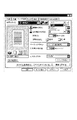
このようにプリンタドライバのプロパティで設定されている内容は設定ファイルとしてOSが提供する構造体(WindowsOSでは、DEVMODEと呼ばれる)に格納される。その構造体には、例えばスプールファイル303に含まれる加工設定中にスプールファイルマネージャ304にストアを行うかどうかの設定が含まれており、スプールファイルマネージャ304がプリンタドライバを介して加工設定を読み込み、ストア指定がなされていた場合、前述したようにスプールファイル303にページ描画ファイルとジョブ設定ファイルとが生成・格納され、図16のようにスプールファイルマネージャのウインドウ画面がポップアップされ、スプールファイル303にスプールされたジョブがリスト表示される。図16には、4つのジョブがスプールされている例を示しており、メニューバーもしくは、そのすぐ下のメニューアイコンを押下することにより、ジョブの操作を行うことができる。メニューバーとメニューアイコンの操作の数は同じである。
【0043】
操作種類としては、ジョブを選択した状態で、「印刷」、中間コードのスプールファイルをそのまま残して印刷を行わせる「セーブして印刷」、印刷設定を考慮したジョブの出力プレビューを見るための「プレビュー」、中間コードのスプールファイルを削除する「削除」、中間コードのスプールファイルのコピーを生成する「複製」、複数の中間コードのスプールファイルのジョブを結合して1つのジョブにする「結合」、結合ジョブを元の複数のジョブに分割する「分割」、単体ジョブもしくは結合ジョブの印刷設定(レイアウト設定やフィニッシング設定等)を変更する「ジョブ編集」、あるジョブの印刷順序を最初にする「先頭に移動」、あるジョブの印刷順序を1つ早くする「1つ上に移動」、あるジョブの印刷順序を1つお則する「1つ下に移動」、あるジョブの印刷順序を最後にする「最後に移動」の以上11個の操作がある。
【0044】
スプールファイルマネージャのウインドウ画面(図16)上で、ある単体ジョブもしくは結合ジョブのプレビュー指定がされた場合、外部メモリ111に格納されているプレビューア306をRAM102にロードし、プレビューア306に対して、スプールファイル303に記述された中間コードのジョブのプレビュー処理を行うように指示する。
【0045】
プレビューア306はスプールファイル303に含まれる中間コードのページ描画ファイル(PDF)を順次読み出し、スプールファイル303に格納されているジョブ設定ファイル(SDF)に含まれる加工設定情報の内容に従って加工し、グラフィックエンジン202に対してGDI関数を出力し、グラフィックエンジン202が自身のクライアント領域に描画データを出力することによって、画面上の出力が可能となる。
【0046】
グラフィックエンジン202は、指定された出力先に応じて適切なレンダリングを行うことが可能である。このことから、プレビューア306は、デスプーラ305同様に、スプールファイル303に含まれる中間コードをスプールファイル303に含まれる加工設定の内容に従って加工し、グラフィックエンジン202を利用して出力する方法で実現可能となる。このようにプリンタドライバで設定されている加工設定をジョブ設定ファイルとしてスプールファイル303に格納し、このジョブ設定ファイルに基づいてページ描画ファイルのデータを加工して出力することにより、実際の描画データがどのように印刷されるか、更には、Nup(Nページの論理ページを1ページの物理ページに縮小配置して印刷する処理)指定されている場合、両面印刷されている場合、製本印刷指定されている場合、スタンプが指定されている場合、それぞれに応じて、プリンタで出力されるものに近い印刷プレビューをユーザに提供することができる。なお、従来の文書作成等のアプリケーションソフトウェアが有しているプレビュー機能は、あくまでそのアプリケーションにおけるページ設定に基づいて描画しているため、プリンタドライバでの印刷設定が反映されず、実際に印刷出力されるプレビューをユーザに認識させることはできなかった。
【0047】
上記のようにプレビュー処理を行うことにより、図17のようにスプールファイル303に含まれる印刷の加工設定の大プレビューがプレビューア306によって画面上に表示され、その後、ユーザの非表示指示によって、プレビューア306がクローズされ、制御がスプールファイルマネージャのウインドウ画面(図16)に移行する。
【0048】
そして、ユーザがプレビューア306によって表示された内容に従って、印刷を行うならば、スプールファイルマネージャ304上で、「印刷」もしくは「セーブして印刷」を指示することにより印刷要求を発行する。印刷要求は前述したように、デスプーラ305によりジョブ設定ファイルに基づいてページ描画ファイルを加工してGDI関数を生成し、グラフィックエンジン202に伝えられ、ディスパッチャ301経由で、プリンタドライバ203に印刷命令が送られ、印刷が実行される。
【0049】
次に、設定変更エディタ307を用いた設定変更について説明する。
【0050】
その実現方法としては、プレビュー同様、図9において「ストア」指定されたジョブに関して設定可能である。同様のフローによりスプールファイルマネージャ304がポップアップされ、スプールされたジョブがリスト表示される。スプールファイルマネージャのウインドウ画面(図16)上で、「ジョブ編集」が指定され、設定変更指示がされた場合、外部メモリ111に格納されている設定変更エディタ307をRAM102にロードし、設定変更エディタ307に対して、現在またはデフォルトの加工設定の表示を行うように指示する。そして図18のようなジョブ設定画面が表示される。
【0051】
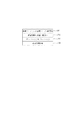
設定変更エディタ307は、「ジョブ編集」が指定されたジョブのジョブ設定ファイルをスプールファイル303から取得し、そのジョブ設定ファイルに指定されている設定項目に基づいて図18のジョブ設定画面のデフォルト値を変更する。図18に示す例では、「ジョブ編集」指定されたジョブのジョブ設定ファイルには、部数:1部、印刷方法:片面、ステイプル:なし、レイアウト:1ページ/枚等が指定されていることになる。
【0052】
この設定変更エディタ307でもスプールファイル303に含まれる中間コードのページ描画ファイルをスプールファイル303に格納されているジョブ設定ファイルに含まれる加工設定の内容に従って加工し、グラフィックエンジン202を用いて自身のクライアント領域に出力することによって、図18に示す画面上の小プレビュー出力が可能となる。またここで、スプールファイル303に格納されているジョブ設定ファイルに含まれる加工設定の内容を変更、修正することが可能である。その際、プリンタドライバ203の設定可能な項目を設定変更エディタ307上のユーザインターフェイスに持っていても、プリンタドライバ203自身のユーザインターフェイスを呼び出しても構わない。図18に示すように、分数、印刷方法(片面、両目、製本印刷)、ステイプル(サドルフィニッシャー等)、ページレイアウト、配置順等の指定ができ、また「詳細設定」を押下することにより、プリンタドライバで指定できる項目の大半を設定しなおすことが可能となる。ただし、解像度、グラフィックモード等の印刷品位に関する設定の変更は許可しないものとする。
【0053】
ここで変更された変更項目は設定変更エディタ307上の認証要求に従い、変更が認証され、制御がスプールファイルマネージャ304に移行する。変更が認証されたものは、印刷設定の変更を保存することになるが、オリジナルのジョブ設定ファイルには保存せずに、ジョブ編集等で用いられるジョブ出力用設定ファイルを新たに生成して保存することになる。ジョブ出力用設定ファイルについての詳細は、図10以降で後述する。
【0054】
そして、ユーザがプレビューア306での確認同様、設定変更内容に従って、印刷を行うならば、スプールファイルマネージャ304上で、印刷要求を発行する。印刷要求はグラフィックエンジン202に伝えられ、ディスパッチャ301経由で、プリンタドライバ203に印刷命令が送られ、印刷が実行される。
【0055】
また、スプールファイルマネージャのウインドウ画面(図16)では、複数の印刷ジョブを結合し、一つの印刷ジョブとして印刷するように指定することが可能である。これも、プレビュー、設定変更同様、図9のプリンタドライバのプロパティにおいて出力先を「ストア」指定されたジョブが前提となる。
【0056】
ユーザが印刷ジョブの結合を行う場合、まず、アプリケーション201からプリンタドライバ203を呼び出し、図9に示すようなユーザインターフェイス上からストアを選択する。前記同様、この選択により、スプールファイル303にストアされ、図16のようにスプールファイルマネージャのウインドウ画面(図16)がポップアップされる。スプールされたジョブはスプールファイルマネージャのウインドウ上にリスト表示される。アプリケーション201から同様の操作をすることにより、スプールファイルマネージャ304上に複数ジョブのリスト表示がされることになる。
【0057】
ここで、複数ジョブを選択し、「結合」が指定された場合、外部メモリ111に格納されている設定変更エディタ307をRAM102にロードし、設定変更エディタ307に対して、リスト上の先頭ジョブまたはデフォルトの加工設定の表示を行うように指示する。そして図18のような結合設定画面が表示される。ここでは、設定変更エディタ307を結合設定画面として用いているが、別モジュールのものを用いても構わない。
【0058】
この設定変更エディタ307は、スプールファイル303に含まれる中間コードのページ描画ファイルをスプールファイル303に格納されているジョブ設定情報に含まれる加工設定の内容に従って加工し、結合ジョブとして指定されたすべてのジョブに対して、グラフィックエンジン202を用いて自身のクライアント領域に出力することによって、画面上の出力を行う。その際、図18に示すプレビュー領域に選択された全てのジョブの小プレビューが可能となる。また、結合ジョブを生成する際に、それぞれの単体ジョブのジョブ設定ファイルを拡張したジョブ出力用設定ファイルを生成する。このジョブ出力用設定ファイルは、ジョブ編集を行う際にも生成されるものであり、1つのジョブに対して1つできるものであり、結合ジョブの場合もまた1つ生成される。
【0059】
ここではそれぞれのジョブに対して、結合する前の加工設定で表示することも、結合ジョブとして統一の加工設定に変更、修正して表示することも可能である。その際、プリンタドライバ203の設定可能な項目を設定変更エディタ307上のユーザインターフェイスに持っていても、プリンタドライバ203自身のユーザインターフェイスを呼び出しても構わない。
【0060】
ここで結合されたジョブ及び変更された変更項目は、前述したように、設定変更エディタ307上の認証要求に従い、変更が認証され、制御がスプールファイルマネージャ304に移行する。これらの操作により、先に選択された複数ジョブは、スプールファイルマネージャのウインドウ上で一つの結合ジョブとして表示される。
【0061】
そして、ユーザがプレビューア306での確認同様、設定変更内容に従って、印刷を行うならば、スプールファイルマネージャ304上で、印刷要求を発行する。印刷要求はグラフィックエンジン202に伝えられ、ディスパッチャ301経由で、プリンタドライバ203に印刷命令が送られ、印刷が実行される。
【0062】
図4は、プリンタ1500の一例である両面印刷機能を有するカラーレーザプリンタの断面図である。
【0063】
このプリンタはホストコンピュータ3000より入力した印刷データに基づいて得られる各色毎の画像データで変調されたレーザ光をポリゴンミラー31により感光ドラム15を走査して静電潜像を形成する。そして、この静電潜像をトナー現像して可視画像を得、これを中間転写体9へ全色について多重転写してカラー可視画像を形成する。そして更に、このカラー可視画像を転写材2へ転写し、転写材2上にカラー可視画像を定着させる。以上の制御を行う画像形成部は、感光ドラム15を有するドラムユニット、接触帯電ローラ17を有する一次帯電部、クリーニング部、現像部、中間転写体9、用紙カセット1や各種ローラ3、4、5、7を含む給紙部、転写ローラ10を含む転写部及び定着部25によって構成されている。
【0064】
ドラムユニット13は、感光ドラム(感光体)15と感光ドラム15のホルダを兼ねたクリーニング機構を有するクリーナ容器14とを一体に構成したものである。このドラムユニット13はプリンタ本体に対して着脱自在に支持され、感光ドラム15の寿命に合わせて容易にユニット交換可能に構成されている。上記感光ドラム15はアルミシリンダの外周に有機光導電体層を塗布して構成し、クリーナ容器14に回転可能に支持されている。感光ドラム15は、図示しない駆動モータの駆動力が伝達されて回転するもので、駆動モータは感光ドラム15を画像形成動作に応じて反時計回り方向に回転させる。感光ドラム15の表面を選択的に露光させることにより静電潜像が形成されるように構成されている。スキャナ部30では、変調されたレーザ光を、モータ31aにより画像信号の水平同期信号を同期して回転するポリゴンミラーにより反射し、レンズ32、反射鏡33を介して感光ドラムを照射する。
【0065】
現像部は、上記静電潜像を可視画像化するために、イエロー(Y)、マゼンダ(M)、シアン(C)の現像を行う3個のカラー現像器20Y、20M、20Cと、ブラック(B)の現像を行う1個のブラック現像器21Bとを備えた構成を有する。カラー現像器20Y、20M、20C及びブラック現像器21Bには、スリーブ20YS、20MS、20CS及び21BSと、これらスリーブ20YS、20MS、20CS、21BSそれぞれの外周に圧接する塗布ブレード20YB、20MB、20CB及び21BBとがそれぞれ設けられる。また3個のカラー現像器20Y、20M、20Cには塗布ローラ20YR、20MR、20CRが設けられている。
【0066】
また、ブラック現像器21Bはプリンタ本体に対して着脱可能に取り付けられており、カラー現像器20Y、20M、20Cは回転軸22を中心に回転する現像ロータリー23にそれぞれ着脱可能に取り付けられている。
【0067】
ブラック現像器21Bのスリーブ21BSは感光ドラム15に対して例えば300μm程度の微小間隔を持って配置されている。ブラック現像器21Bは、器内に内蔵された送り込み部材によってトナーを搬送すると共に、時計回り方向に回転するスリーブ21BSの外周に塗布ブレード21BBによって塗布するように摩擦帯電によってトナーへ電荷を付与する。また、スリーブ21BSに現像バイアスを印加することにより、静電潜像に応じて感光ドラム15に対して現像を行って感光ドラム15にブラックトナーによる可視画像を形成する。
【0068】
3個のカラー現像器20Y、20M、20Cは、画像形成に際して現像ロータリー23の回転に伴って回転し、所定のスリーブ20YS、20MS、20CSが感光ドラム15に対して300μm程度の微小間隔を持って対向することになる。これにより所定のカラー現像器20Y、20M、20Cが感光ドラム15に対向する現像位置に停止し、感光ドラム15に可視画像が作成される。
【0069】
カラー画像形成時には、中間転写体9の1回転毎に現像ロータリー23が回転し、イエロー現像器20Y、マゼンダ現像器20M、シアン現像器20C、次いでブラック現像器21Bの順で現像工程がなされ、中間転写体9が4回転してイエロー、マゼンダ、シアン、ブラックのそれぞれのトナーによる可視画像を順次形成し、その結果フルカラー可視画像を中間転写体9上に形成する。
【0070】
中間転写体9は、感光ドラム15に接触して感光ドラム15の回転に伴って回転するように構成されたもので、カラー画像形成時に時計回り方向に回転し、感光ドラム15から4回の可視画像の多重転写を受ける。また、中間転写体9は画像形成時に後述する転写ローラ10が接触して転写材2を挟持搬送することにより転写材2に中間転写体9上のカラー可視画像を同時に多重転写する。中間転写体の外周部には、中間転写体9の回転方向に関する位置を検知するためのTOPセンサ9a及びRSセンサ9bと、中間転写体に転写されたトナー像の濃度を検知するための濃度センサ9cが配置されている。
【0071】
転写ローラ10は、感光ドラム15に対して接離可能に支承された転写帯電器を備えたもので、金属軸を中抵抗発泡弾性体により巻回することによって構成されている。
【0072】
転写ローラ10は、図4に実線で示すように中間転写体9上にカラー可視画像を多重転写している間は、カラー可視画像を乱さぬように下方に離開している。そして、上記中間転写体9上に4色のカラー可視画像が形成された後は、このカラー可視画像を転写材2に転写するタイミングに合わせてカム部材(不図示)により転写ローラ10を図示点線で示す上方に位置させる。これにより転写ローラ10は転写材2を介して中間転写体9に所定の押圧力で圧接すると共に、バイアス電圧が印加され、中間転写体9上のカラー可視画像が転写材2に転写される。
【0073】
定着部25は、転写2を搬送させながら、転写されたカラー可視画像を定着させるものであり、転写材2を加熱する定着ローラ26と転写材2を定着ローラ26に圧接させるための加圧ローラ27とを備えている。定着ローラ26と加圧ローラ27とは中空状に形成され、内部にそれぞれヒータ28、29が内蔵されている。即ち、カラー可視画像を保持した転写材2は定着ローラ26と加圧ローラ27とにより搬送されると共に、熱及び圧力を加えることによりトナーが表面に定着される。
【0074】
可視画像定着後の転写材2は、その後排紙ローラ34、35、36によって排紙部37へ排出して画像形成動作を終了する。
【0075】
クリーニング手段は、感光ドラム15上及び中間転写体9上に残ったトナーをクリーニングするものであり、感光ドラム15上に形成されたトナーによる可視画像を中間転写体9に転写した後の廃トナーあるいは、中間転写体9上に作成された4色のカラー可視画像を転写材2に転写した後の廃トナーは、クリーナ容器14に蓄えられる。
【0076】
印刷される転写材(記録用紙)2は、給紙トレイ1から給紙ローラ3により取り出されて中間転写体9と転写ローラ10との間に挟まれるようにして搬送されてカラートナー画像が記録され、定着部25を通過してトナー像が定着される。片面印刷の場合には、案内38が上方の排紙部に記録用紙を導くように搬送経路を形成するが、両面印刷に対しては、下方の両面ユニットに導くように経路を形成する。
【0077】
両面ユニットに導かれた記録用紙は、搬送ローラ40によりトレイ1の下部(二点鎖線で示す搬送経路)に一旦送り込まれた後に逆方向に搬送され、両面トレイ39に送られる。両面トレイ39上では、用紙は給紙トレイ1に載置された状態とは表裏が逆になり、また搬送方向について前後が逆になっている。この状態で再びトナー像の転写、定着を再度行うことで、両面印刷ができる。
【0078】
図5は、スプーラ302における、スプールファイル303の生成におけるページ単位保存ステップの処理をフローチャートで示したものである。
【0079】
まずステップ501では、スプーラ302は、アプリケーションからグラフィックエンジン202を介して印刷要求を受け付ける。アプリケーションにおいては、図8に示すような印刷設定を入力するダイアログが表示され、このダイアログから入力された印刷設定がプリンタドライバよりスプーラ303に渡される。図8に示す設定入力ダイアログにおいては、801のような1物理ページにレイアウトする論理ページの数を決定するような設定項目等を含んでいる。
【0080】
ステップ502では、スプーラ302は、受け付けた印刷要求がジョブ開始要求か判定し、もしステップ502でジョブ開始要求であると判断した場合には、ステップ503に進み、スプーラ302は、中間データを一時的に保存するためのスプールファイル303を作成する。続いて、ステップ504では、スプーラ302は、スプールファイルマネージャ304へ中間データ作成処理の進捗を通知し、続くステップ505でスプーラ302のページ数カウンタを1に初期化する。ここで、スプールファイルマネージャ304においては、中間データ作成処理が開始されたジョブに対するジョブの情報や加工設定などをスプールファイル303より読み込み、記憶する。
【0081】
一方、ステップ502において、ジョブ開始要求ではなかったと判断した場合には、ステップ506に進む。
【0082】
ステップ506では、スプーラ302は、受け付けた要求がジョブ終了要求かどうかの判別を行う。ジョブ終了要求でないと判断した場合には、ステップ507に進み、改ページかどうかの判別を行う。もしもステップ507で改ページであると判断した場合には、ステップ508に進み、スプールファイルマネージャ304へ中間データ作成処理の進捗を通知する。そしてページ数カウンタをインクリメントして、中間コードを格納しているページ描画ファイルを閉じ、次のページ描画ファイルを生成する。このようにページ描画ファイルは、アプリケーションから出力される論理ページ単位に生成される。
【0083】
ステップ507において、受け付けた印刷要求が改ページではないと判断した場合には、ステップ509に進み、スプーラ302は、ページ描画ファイルへの中間コードの書き出しの準備を行う。
【0084】
次に、ステップ510では、印字要求をスプールファイル303へ格納するため、スプーラ302は、印字要求のDDI関数の中間コードへの変換処理を行う。ステップ511では、スプーラ302は、ステップ510において格納可能な形に変換された印刷要求(中間コード)をスプールファイル303のページ描画ファイルへ書き込む。その後、ステップ501に戻り、再びアプリケーションからの印刷要求を受け付ける。この一連のステップ501からステップ511までの処理を、アプリケーションよりジョブ終了要求(End Doc)を受け取るまで続ける。また、スプーラ302は、同時にプリンタドライバ203からDEVMODE構造体に格納されている加工設定等の情報を取得し、ジョブ設定ファイルとしてスプールファイル303に格納する。一方、ステップ506にて、アプリケーションからの印刷要求がジョブ終了であると判断した場合には、アプリケーションからの印刷要求は全て終了であるので、ステップ512に進み、スプールファイルマネージャ304へ中間データ作成処理の進捗を通知し、処理を終える。
【0085】
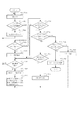
図6は、スプールファイルマネージャ304における、スプールファイル303の生成プロセスと以降説明する印刷描画データ生成プロセスの間での制御の詳細をフローチャートで示したものである。
【0086】
ステップ601では、スプールファイルマネージャ304は、スプーラ302あるいはデスプーラ305からの中間データ作成処理の進捗通知を受け付ける。
【0087】
ステップ602では、スプールファイルマネージャ304は、もし進捗通知が前述のステップ504において通知されるスプーラ302からの印刷開始通知であるかどうか判定し、もしそうであればステップ603へ進み、印刷の加工設定をスプールファイル303から読み込み、ジョブの管理を開始する。一方、ステップ602において、スプーラ302からの印刷開始通知でなければステップ604へ進み、スプールファイルマネージャ304は、進捗通知が前述のステップ508において通知されるスプーラ302からの1論理ページの中間データ作成終了通知(改ページ)であるかどうか判定する。ここで1論理ページの中間データ作成終了通知であればステップ605へ進み、この論理ページに対する論理ページ情報を格納する。そして、続くステップ606では、この時点でスプールが終了したn論理ページに対して、1物理ページの印刷が開始できるかを判定する。ここで、印刷可能である場合はステップ607へ進み、印刷する1物理ページに対して割り付けれられる論理数から物理ページ番号を決定する。
【0088】
物理ページの計算については、例えば、加工設定が1物理ページに4論理ページを配置するような設定(例えば、4面ハガキに対する4ページ印刷の設定)の場合、第1物理ページは第4論理ページがスプールされた時点で印刷可能となり、第1物理ページとなる。続いて、第2物理ページは第8論理ページがスプールされた時点で印刷可能となる。
【0089】
また、論理ページ数の総数が1物理ページに配置する論理ページ数の倍数でなくても、ステップ512におけるスプール終了通知によって1物理ページに配置する論理ページが決定可能である。
【0090】
そして、ステップ608では、図10に示すような形式で、印刷可能となった物理ページを構成する論理ページ番号と、その物理ページ番号などの情報がジョブ出力用設定ファイル(物理ページ情報を含むファイル)に保存され、物理ページ情報が1物理ページ分追加されたことがデスプーラ305に通知される。その後ステップ601に戻り、次の通知を待つ。本実施例においては、印刷処理の1ページ(Nページ印刷の場合は、論理ページがNページ分)、即ち1物理ページを構成する論理ページがスプールされた時点で印刷ジョブのスプールが全て終了していなくても印刷処理が可能である。
【0091】
一方、ステップ604において、進捗通知がスプーラ302からの1論理ページの印刷終了通知でなかった場合ステップ609へ進み、スプールファイルマネージャ304は、前述のステップ512において通知されるスプーラ302からのジョブ終了通知であるかどうかを判定する。ここで、ジョブ終了通知である場合、前述のステップ606へ進む。一方、ジョブ終了通知でない場合、ステップ610へ進み、スプールファイルマネージャ304は、受け付けた通知がデスプーラ305からの1物理ページの印刷終了通知であるかどうか判定する。ここで、1物理ページの印刷終了通知である場合はステップ611へ進み、加工設定の印刷処理が全て終了したかを判定する。加工設定の印刷処理がすべて終了した場合、ステップ612へ進み、デスプーラ305に印刷終了の通知を行う。
【0092】
一方、加工設定に対する印刷がまだ終了していないと判断した場合、前述の606へ進む。本実施例におけるデスプーラ305は印刷処理を行う単位として1物理ページ数を想定している。また、ステップ608では、1物理ページの印刷処理を行うのに必要な情報をファイルに逐次保存し、再利用可能な形式にしているが、再利用不要な場合には、共有メモリ等高速な媒体を使用し、1物理ページ単位で次々と上書きする実装にして、速度とリソースを節約するような実装形式であってもよい。また、デスプールの進捗よりもスプールの進捗の方が早い場合や全ページのスプール終了後からデスプールが開始されるような場合には、ステップ608で1物理ページ毎にページ印刷可能を通知せずに、デスプール側の進捗に応じて、複数物理ページもしくは全物理ページが印刷可能になったという通知内容にして、通知回数を節約することが可能である。
【0093】
ステップ610において、通知がデスプーラ305からの1物理ページの印刷終了通知でないと判断された場合、ステップ613へ進み、スプールファイルマネージャ304は、デスプーラ305からの印刷終了通知かどうかを判定する。通知がデスプーラ305からの印刷終了通知と判定された場合、ステップ614へ進み、スプールファイルマネージャ304は、スプールファイル303の該当するページ描画ファイルの削除を行い処理を終える。ただし、一方、デスプーラ305からの印刷終了通知でなかった場合はステップ615へ進み、その他通常処理を行い、次の通知を待つ。
【0094】
図7は、デスプーラ305における、第一種の描画関数を生成するプロセスの詳細をフローチャートで示したものである。
【0095】
デスプーラ305は、スプールファイルマネージャ304からの印刷要求に応じて、スプールファイル303から必要な情報(ページ描画ファイルおよびジョブ設定ファイル)を読み出して第一種の描画関数を生成する。生成された第一種の描画関数におけるプリンタへの転送方法については図3で説明した通りである。
【0096】
第一種の描画関数の生成では、まず、ステップ701において、前述のスプールファイルマネージャ304からの通知を入力する。続くステップ702では、デスプーラ305は、入力された通知がジョブの終了通知かどうか判定し、ジョブ終了通知であるならばステップ703へ進み、終了フラグを立て、ステップ705へ進む。一方、ステップ702においてジョブ終了通知でない場合は、ステップ704に進み、前述のステップ608における1物理ページの印刷開始要求が通知されたかどうか判定する。ステップ704において開始要求と判定されなかった場合は、ステップ710へ進み、その他エラー処理を行い、ステップ701へ戻り次の通知を待つ。
【0097】
一方、ステップ704において1物理ページの印刷開始要求と判定された場合は、ステップ705へ進み、デスプーラ305は、ステップ704で通知を受けた印刷処理可能な物理ページのIDを保存する。続くステップ706では、デスプーラ305は、ステップ705で保存した物理ページIDのすべてのページに関して印刷処理が済んでいるかどうか判定する。ここで全物理ページの処理が済んでいる場合は、ステップ707へ進み、前述のステップ703で終了フラグが立てられているのか判定する。終了フラグがたっている場合は、ジョブの印刷が終了したとみなし、デスプーラ305の処理終了の通知をスプールファイルマネージャ304に通知し、処理を終える。ステップ707で、終了フラグが立っていないと判定された場合は、ステップ701へ戻り次の通知を待つ。
【0098】
一方、ステップ706で、印刷可能な物理ページが残っていると判定された場合には、ステップ708へ進み、デスプーラ305は、保存された物理ページIDから未処理の物理ページIDを順に読み出し、読み出した物理ページIDに対応する物理ページの描画関数の生成に必要な情報を読み込み、印刷処理を行う。ここでいう印刷処理とは、スプールファイル303に格納された中間データ形式の印刷要求命令をデスプーラ305においてグラフィックエンジン202が認識可能な形式(GDI関数)に変換し、転送する処理に相当する。
【0099】
本実施例のような、複数論理ページを1物理ページにレイアウトするような加工設定(以下Nページ印刷)については、このステップで縮小配置を考慮にいれながら変換する。必要な印刷処理が終えたならば、続くステップ709において1物理ページの第二種の描画関数の生成終了の通知をスプールファイルマネージャ304に対して行う。そして再びステップ706へ戻り、ステップ705で保存しておいた印刷可能な物理ページIDすべてについて印刷処理を行うまで繰り返す。
【0100】
以上が、ディスパッチャ301、スプーラ302、スプールファイルマネージャ304、デスプーラ305を用いた印刷処理の流れである。上記のように処理することにより、スプーラ302が中間コードを生成してスプールファイル303に格納するタイミングでアプリケーション201が印刷処理から開放されるので、プリンタドライバ203に直接出力するよりも短時間で済む。また、スプールファイル303にプリンタドライバの印刷設定を踏まえた中間ファイル(ページ描画ファイル、ジョブ設定ファイル)として一時保存しているので、実際に印刷されるべき印刷プレビューをユーザに認識させることや、複数のアプリケーションにより生成した印刷ジョブの結合や並び替えが可能となり、印刷設定の変更を行う場合にも、再度アプリケーションを立ち上げて印刷をすることなしにユーザに行わせることを可能とする。
【0101】
ここで、スプーラ302を用いた印刷処理において、デスプーラ305によりグラフィックエンジン202への印刷要求時にジョブ出力用設定ファイルが生成されるが、プレビューやジョブ結合等を行う場合もジョブ出力用設定ファイルが生成される。ジョブ出力用設定ファイルは、単体ジョブの場合はジョブ設定ファイルと同等のものであり、結合ジョブの場合は複数のジョブ設定情報に基づいて生成されるものである。ここでジョブ出力用設定ファイルについて説明する。
【0102】
図10は、ステップ608において、スプールファイルマネージャ304が生成する印刷可能となった物理ページを構成する情報を保存しているジョブ出力用設定ファイルの例を示す。フィールド1001は、ジョブを識別するためのIDで、本情報を保存しているファイル名や共有メモリの名称という形で保持することも可能である。フィールド1002はジョブ設定情報である。ジョブ設定情報には、グラフィックエンジン202に対してジョブの印刷を開始するために必要な構造体、Nページ印刷の指定、ページ枠などの追加描画の指定、部数、ステイプルなどのフィニッシング指定など、1つのジョブに対して1つしか設定できない情報が含まれている。ジョブ設定情報1002には、ジョブに対する機能に応じて必要なだけ情報が保存される。フィールド1003はジョブの物理ページ数で、本フィールド以降、この数の分だけ物理ページ情報が保存されていることを示す。本実施例では、印刷可能な物理ページ数を通知する方式であるので、このフィールドは無くても動作可能である。これ以降、フィールド1004から最後までフィールド1003の数だけ物理ページ情報が格納される。物理ページ情報については図12で説明する。
【0103】
図11は、図10のフィールド1002に図示されたジョブ設定情報の一例である。フィールド1101は全物理ページ数である。フィールド1102は、全論理ページ数である。フィールド1101および1102は、印刷ジョブに対して、ページ数などを付加情報として追加する場合などに利用する。印刷処理が続いている際には、両フィールドは暫定的な値、もしくは、印刷処理(本実施例におけるデスプーラ305の描画関数の生成処理)が終了するまでスプールファイルマネージャ304は印刷可能な物理ページの情報の作成を延期する。フィールド1103は本印刷ジョブを何部印刷するかを指定する部数情報である。フィールド1104は、フィールド1103で複数部印刷する設定の場合、部単位で印刷するかどうかの指定である。フィールド1104はステイプル、パンチ、Z折などのフィニッシング情報で、プリンタ本体もしくは外部にフィニッシャーがある場合に指定される。フィールド1106は付加印刷情報で、ページ枠などの飾り、日付などの付加情報、ユーザ名、ページ数、ウォーターマーク印刷等、ジョブに対して付加する情報が保存される。機能が増えるに従って本ジョブ設定情報に含まれるフィールドの数も増加し、例えば、両面印刷が可能な場合は、両面印刷の指定を保存するフィールドが追加される。
【0104】
図12は、図10のフィールド1004に図示された物理ページ情報の一例を示す。最初のフィールド1201は物理ページ番号で、印刷順序の管理や、物理ページ番号を追加印刷する際に使用される値である。フィールド1202は物理ページ設定情報で、物理ページ毎にレイアウトやカラー・モノクロの指定が可能である場合、レイアウトやカラー・モノクロの設定が保存される。フィールド1203は本物理ページに割り付けられる論理ページ数で、1物理ページに4ページを割り付ける場合には4もしくは4ページ印刷を示すIDが保存される。フィールド1204以降はフィールド1203で指定された数だけ論理ページの情報が保存される。アプリケーション201から印刷されたページ数によっては、1203で指定されるページ数よりも実際のページデータ数が少なくなる場合がある。その場合には、論理ページ情報に空ページを示す特別なデータを保存して対応する。
【0105】
図13は、1202の物理ページ設定情報の例である。フィールド1301は物理ページ上への論理ページの配置順で、Nページ印刷で、物理ページ上に論理ページを配置する順番(左上から横へ、左上から下へ等)の指定が保存されている。システムによっては、配置順ではなく、フィールド1204以降の論理ページ情報の順番をページ番号順ではなく、配置順に応じた順序で配することで1301の設定を代用する場合もある。フィールド1302は両面印刷の表・裏の情報で、例えば綴じ代を表裏でそろえる際に使用される。フィールド1303はカラーページかモノクロページかの指定で、プリンタがモノクロモードとカラーモードを持つ場合、カラーページとモノクロページが混在する文書で、カラーページをカラーモードで、モノクロページをモノクロモードで印刷したい場合などに使用される値である。この情報を持つことにより、オートカラーモードとして、ページ単位にカラープリンタで処理を変更することが可能となる。つまり、カラーページは、中間転写体(中間転写ドラム、中間転写ベルト)もしくは転写体(転写ドラム、転写ベルト)がデバイスカラーの数分、YMCKなら4回転し、モノクロページは、ブラックだけ1回転することにより転写制御することを可能とする。フィールド1304は付加印刷情報で、物理ページに対して、ページ数や、日付などの付加情報を印刷する場合に使用される。物理ページ設定情報も、システムの機能に応じてフィールドが追加される。
【0106】
図14は、1204で示された論理ページ情報の一例を示す。フィールド1401は論理ページのIDで、このIDを利用して、スプールファイル303から論理ページに対応するページ描画ファイルの中間コードを参照する。このIDを利用して論理ページの中間コードへアクセス可能であれば良く、ファイルやメモリポインタであっても、論理ページを構成する中間コード自身が入っていてもよい。フィールド1402は論理ページ番号で論理ページ番号を付加情報として印刷する場合や、論理ページIDの補助情報に使用される。フィールド1403のフォーマット情報には、論理ページ単位で指定可能である各種設定項目が保存される。例えば、ページ枠などの付加印刷情報、拡縮率などの論理ページ単位に指定される各種設定の情報が保存される。また、必要であれば、論理ページ単位のカラー・モノクロ情報などの論理ページに対する属性情報を保存する事も可能である。逆に、論理ページ単位で設定を切り替える事や論理ページ単位での属性情報が不要であるようなシステムでは、フィールド1403は不要である。
【0107】
ジョブ出力用設定ファイルは、上記のように構成されている。なお、ジョブ設定ファイルもほぼ同様であり、印刷体裁(片面、両面、製本印刷)、印刷レイアウト(Nup、ポスター印刷)、付加情報(ウォーターマーク、日付、ユーザ名の付加)、部数、用紙サイズ情報がジョブとして有しており、物理ページ毎に、論理ページの配置順、両面印刷の表面か、裏面か、カラーモード等から構成されている。
【0108】
更に、図3では、これまで説明した拡張システムに加えて、ジョブの設定変更機能を持つ設定変更エディタ307を配した例を示している。本実施例ではジョブの設定内容は、単体ジョブは、ジョブ設定ファイルに、また結合ジョブは、図10に示したジョブ出力用設定ファイル中に含まれており、中間コードを保存しているページ描画ファイル303とは独立しているため、ジョブ出力用設定ファイルを作り変えることでジョブの設定変更が可能である。設定変更エディタ307は単独で、あるいはスプールファイルマネージャ304と連携して、ジョブ出力用設定ファイルを作り変え、あるいは、一部を書き換えることでジョブの設定変更機能を実現している。
【0109】
図15は、設定変更エディタ307におけるジョブ設定変更処理プロセスの詳細をフローチャートで示したものである。
【0110】
まずステップ1501では、設定変更エディタは、ジョブ設定ファイルもしくはジョブ出力用設定ファイルを読み込む。ジョブ出力用設定ファイルはプレビューア305、デスプーラ303が読み込むものと同じファイルである。次に、ステップ1502へ進み、読み込んだ結果を、ユーザに表示する。ステップ1503で、図18に示したようなユーザインターフェイス上で、ユーザとの対話を行い、前述したメニューの指定等により設定内容を変更する。このステップは、対話形式でなく、ファイルなどに書きこまれた設定変更の内容に応じて変更するバッチ形式でもよい。次にステップ1504へ進み、ステップ1501で設定変更エディタは、最初に読み込んだ内容と、現在指定されている設定内容に変更があったかどうかの判定を行う。設定内容に変更が合った場合は、ステップ1505へ進み、新規のジョブ出力用設定ファイルを生成し、変更があったことをスプールファイルマネージャに通知して終了する。
【0111】
ステップ1505で、変更がないと判定された場合は、変更がなかったことをスプールファイルマネージャに通知して終了する。このように新規のジョブ出力用設定ファイルを生成するが、図18のユーザインターフェイス画面において、「OK」ボタンが選択されることにより、新規のジョブ出力用設定ファイルが有効となり、古いジョブ出力用設定ファイルは削除される。また、ジョブ出力用設定ファイルからの変更ではなく、単体ジョブのジョブ設定ファイルの場合は削除せずに保存しておく。また、図18の画面で「初期状態に戻す」ボタンが選択された場合は、新規のジョブ出力用設定ファイルを削除し、古いジョブ出力用設定ファイルが有効となり、表示に反映させる。本実施例では、設定変更エディタ307を別モジュールとして説明しているが、単にスプールファイルマネージャ304のユーザインターフェイスの一部であってもよい。設定変更エディタ307で実際に変更内容をジョブ出力用設定ファイルに書きこまずに、設定変更の内容のみをスプールファイルマネージャ304へと通知するだけで、実際のジョブ出力用設定ファイルの変更はスプールファイルマネージャ304側で行う実装形式でもよい。
【0112】
図3では、更に、複数印刷ジョブを結合し、一つの印刷ジョブとして印刷する拡張システムが図示されているが、結合ジョブをデスプール・プレビューするための拡張について説明する。
【0113】
通常、中間形式のスプールファイル303はジョブ単位で作成される。単独ジョブの場合は、処理対象ジョブファイル中の各論理ページの中間コードを順に読み出して処理を行うので、フィールド1401の論理ページIDは、各論理ページがファイルのどこに位置しているのかを示す相対あるいは絶対オフセットで実現可能である。結合ジョブの場合はフィールド1401のジョブIDから、スプールファイルと、そのジョブに属するページ情報を特定する必要がある。本実施例では、スプールファイルを識別するIDを論理ページIDに付加することで、スプールファイルを特定する方式とする。この場合、主な変更点はフィールド1401のみで済む。スプールファイルが識別できれば、ページ部分の読み込みは単独ジョブの処理と同じロジックで処理することが可能であるからである。また、スプールファイルが各論理ページ毎に別ファイルの形で保存されている場合は、論理ページのファイル名をそのままフィールド1401の論理ページIDとする実装形もある。
【0114】
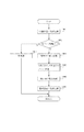
図19は本発明を特徴付けるNページ印刷機能を実現する部分であるデスプーラ305およびスプールファイルマネージャ304の処理を説明するためのフローチャートを示した図である。これを用い、本発明の処理フローを説明する。
【0115】
前述したように、一連の印刷処理の中で、デスプーラ305は、スプールファイルマネージャ304からの印刷要求に応じて、スプールファイル303から必要な情報(ページ描画ファイルおよびジョブ設定ファイル)を読み出して第二種の描画関数を生成する。ここで、デスプーラ305が印刷処理(GDIに対する描画関数を生成する処理)を開始する前に、スプールファイルマネージャ304における各処理が行われる。
【0116】
まず、スプールファイルマネージャ304は、スプーラ302からの通知(改ページ通知もしくはスプール終了通知)に基づいて印刷要求が可能である場合に、印刷体裁の取得処理(ステップ1901)を行う。これは、スプールファイルマネージャ304が、ジョブ設定ファイルより、現在のジョブ(アプリケーションから印刷要求のあったドキュメントに相当する一覧の描画データ)で所望されている印刷体裁を取得する処理である。ここでは、4ページのデータを1物理ページに並べる印刷体裁(4ページ印刷)が選択されているものとする。なお、この印刷体裁は、前述したようにプリンタドライバのプロパティUI(ユーザインタフェース)を介してユーザにより設定されている設定値である。
【0117】
そして、ステップ1902において、スプールファイルマネージャ304は、取得した印刷体裁の設定情報がNページ印刷の設定であるか否かの判定処理を行う。Nページ印刷であると判断された場合は、ステップ1904に処理を進め、Nページ印刷でないと判断された場合は、ステップ1903に処理を進める。先に示したように、4ページ印刷が選択されていると仮定しているため、ここではNページ印刷であると判定されることになる。
【0118】
ステップ1904では、スプールファイルマネージャ304は、物理用紙に配置する論理ページの配置領域を算出するN等分処理を行う。これは、図21(a)で示されるように、指定されている出力用紙を先に取得したNページ情報に従ってN等分する処理である。ここでは、4ページ印刷が指定してあるので、図21(a)のように4等分される。
【0119】
そしてステップ1905において、スプールファイルマネージャ304は、前記ステップでN等分された用紙の配置領域に対するオフセット処理を行う。これは、先にN等分された各領域に印刷マージンに相当する幅を各領域の四辺から減算し、オフセット処理を行い、各領域の有効印字領域を確定させる処理である。これにより、図21(b)で示されるようにオフセット処理後のN等分された用紙の配置領域が求められる。図21の(b)において、A〜Dは既にページ描画ファイルおよびジョブ設定ファイルより取得している値(印刷マージン)であり、4等分された各領域が同様のオフセット値になるように、つまり、A=A’、B=B’、C=C’、D=D’となるように配置領域が設定される。
【0120】
そしてステップ1906において、スプールファイルマネージャ304は、縮小率の算出処理を行う。これは、先に算出された各配置領域(本実施例では、有効印字領域で四辺を均等化した領域)内にページ描画ファイルから取得された各々のページが収まるように縮小率を算出する処理である。図21(c)で示すように、例えば、E×Fで示される配置領域に対して論理ページG×Hのページ情報を収める場合、E/G、F/Hの小さい方が縮小率として選択され、領域に収まるように配置されるわけである。その際、スプールファイルマネージャ304により、縮小された論理ページが配置領域のそれぞれの辺に対して中心にくるようにセンタリング配置処理が実行される。これにより、全ての領域が設定され、次のステップ1907において、スプールファイルマネージャ304はデスプーラ305に対して描画関数の生成処理を依頼し、デスプーラ305は、スプールファイルマネージャ304により決定された縮小率や配置領域に対して、スプールファイル303から読み出したスプールデータを加工処理し、グラフィックエンジン202が解釈可能な描画関数(GDI関数)を再生成し、デスプーラ305はグラフィックエンジン202に対して再生成した描画関数を出力する。
【0121】
グラフィックエンジン202はデスプーラ305から入力される第一種の描画関数(GDI関数)をプリンタドライバ203が解釈可能な第二種の描画関数(DDI関数)に変換し、ディスパッチャ301に出力する。ディスパッチャ301はグラフィックエンジン202から受け取った描画関数(DDI関数)をプリンタドライバ203に渡す。ここで、前述したようにディスパッチャ301は、描画関数を受けた場合に、グラフィックエンジン202に第一種の描画関数を渡したモジュールがアプリケーション201であるかデスプーラ305であるかを判断し、デスプーラ305であると判断された場合に、第二種の描画関数をプリンタドライバ203に渡すことになる。プリンタドライバ203は、ディスパッチャ301から受け取った第二種の描画関数であるDDI関数に基づいてページ単位にPDLで記述される印刷データを生成し、システムスプーラ204に出力する。システムスプーラ204は、印刷データをプリンタ1500に順次送出する。このように、スプーラ302により描画関数を一度スプールし、デスプーラ305で編集処理して再度グラフィックエンジン202経由でプリンタドライバ203は描画関数を受け取ることにより、Nページ印刷機能やスタンプ機能やページ制御(順序変更、削除など)などの機能をプリンタドライバ203内に組み込む必要がなくなるため、プリンタドライバモジュール203は一般化した共通プリンタドライバとして作成でき、ここの機能拡張はスプールファイルマネージャ304およびデスプーラ305により吸収でき、開発工程が短くて済むという効果も得られる。また、ディスパッチャ301、スプーラ302、スプールファイルマネージャ304、デスプーラ305は、プリンタベンダーにより1つの仮想プリンタドライバとして情報処理装置に組み込まれることになり、プリンタドライバがNページ機能を提供することにもなる。
【0122】
このように処理することにより、物理用紙をN等分した領域に対して中央に論理ページが配置されるNページ印刷機能を情報処理装置に組み込まれるソフトウェアで提供することが可能となる。
【0123】
[第二実施例]
本第一実施例では、物理用紙をN等分した領域に対して中央に論理ページが配置されるNページ印刷機能(以下、物理Nページ印刷と呼ぶ)をプリンタドライバで提供することについて説明した。本第二実施例では、Nページ印刷を行う場合に、物理用紙に対する印刷可能領域に対してNページ分の論理ページを縮小配置するNページ印刷機能(以下、印刷可能領域Nページ印刷と呼ぶ)と物理Nページ印刷のいずれの機能を用いるかを切り替える処理について説明する。
【0124】
この物理Nページ印刷と印刷可能領域Nページ印刷との切替処理について、図20を用いて説明する。
【0125】
前述したように、一連の印刷処理の中で、デスプーラ305は、スプールファイルマネージャ304からの印刷要求に応じて、スプールファイル303から必要な情報(ページ描画ファイルおよびジョブ設定ファイル)を読み出して描画関数を生成する。
【0126】
実施例同様、ステップS2001では、スプールファイルマネージャ304は、印刷体裁の取得処理を行う。これは、ジョブ設定ファイルより、現在処理中の印刷ジョブで所望されている(設定されている)印刷体裁を取得する処理である。
【0127】
そして、ステップ2002において、スプールファイルマネージャ304は、物理Nページ印刷情報(以下、物理Nページ印刷条件とも呼ぶ)の取得処理を行う。本実施例における物理Nページ印刷条件とは、ステップ2001で取得された情報がNページ印刷である場合に、どのNページ印刷を物理Nページ印刷とするかの条件である。例えば、図22(a)のように各フラグを2〜16ページ印刷に割り当て、該当するNページ印刷は前述した物理Nページ印刷を用いて印刷し、該当しないNページ印刷は前述した印刷可能領域Nページ印刷を用いて印刷をするということである。ここでは、4ページ印刷であり、図22(b)のようにフラグが設定されているものとする。この物理Nページ印刷情報は、スプールファイルマネージャ304がプリンタドライバ203から取得するが、プリンタドライバ203は、デバイス(本実施例では、プリンタ1500)から直接取得するものである。これは、図9に示すプリンタドライバのプロパティUIにおいて、「デバイスの設定」シートを開くことにより、図示省略した「デバイス情報の取得」ボタンをユーザが押下する指示をすることをトリガーとして、デバイス情報取得モジュールが起動されて、外部デバイス(本実施例ではプリンタ1500に相当する。また、図示省略したプリントサーバであってもよい。)からデバイス情報を取得する。デバイス情報は、デバイスに装着されているオプションの構成や、本物理Nページ印刷情報を含んでいる。
【0128】
その後、ステップ2003において、スプールファイルマネージャ304は、ステップ2001で取得した情報に基づいて、印刷要求のあった印刷ジョブがNページ印刷であるか否かの判定を行う。Nページ印刷の指定がある場合はステップ2004に処理が進み、Nページ印刷でない通常の印刷である場合はステップ2005に処理が進む。なおここでは、先に示したように4ページ印刷が選択されていると仮定しているため、Nページ印刷であると判定されることになる。
【0129】
そしてステップ2004において、スプールファイルマネージャ304は、現在指定されているNページ印刷が、第一実施例で前述した物理Nページ印刷であるか、印刷可能領域Nページ印刷であるかの判定を行う。この判定処理により物理Nページ印刷であると判定された場合はステップ2006に処理を進め、また、物理Nページ印刷でないと判定された(印刷可能領域Nページ印刷であると判定された)場合はステップ2007に処理を進める。また、この判定処理は、ステップ2002で取得された物理Nページ印刷条件に基づいて、現在指定されているNページ印刷が、物理Nページ印刷であるか、通常のNページ印刷であるかを判定することにより実現する。ここでは、図22(b)のフラグが設定してあると仮定しているので、これは、4ページ印刷は物理Nページ印刷を行うという意味である。所望するNページ印刷は、4ページ印刷であるので、ステップ2006に処理を進め、前述した第一実施例と同様のフローにより、4ページの物理Nページ印刷が行われることとなる。
【0130】
すなわち、ステップ2006では、スプールファイルマネージャ304は、物理用紙に配置する論理ページの配置領域を算出するN等分処理を行う。これは、図21(a)で示されるように、指定されている出力用紙を先に取得したNページ情報に従ってN等分する処理である。ここでは、4ページ印刷が指定してあるので、図21(a)のように4等分される。
【0131】
そしてステップ2008において、スプールファイルマネージャ304は、前記ステップ2006でN等分された用紙の配置領域に対するオフセット処理を行う。これは、先にN等分された各領域に印刷マージンに相当する幅を各領域の四辺から減算し、オフセット処理を行い、各領域の有効印字領域を確定させる処理である。
【0132】
そしてステップ2009において、スプールファイルマネージャ304は、縮小率の算出処理を行う。これは、先に算出された各配置領域(本実施例では、有効印字領域で四辺を均等化した領域)内にページ描画ファイルから取得された各々のページが収まるように縮小率を算出する処理である。これにより、全ての領域が設定され、次のステップ2010において、スプールファイルマネージャ304はデスプーラ305に対して描画関数の生成処理を依頼し、デスプーラ305は、スプールファイルマネージャ304により決定された縮小率や配置領域に対して、スプールファイル303から読み出したスプールデータを加工処理し、グラフィックエンジン202が解釈可能な描画関数(GDI関数)を再生成し、デスプーラ305はグラフィックエンジン202に対して再生成した描画関数を出力する。
【0133】
また、ステップ2004の判定処理で物理Nページ印刷でないと判定された場合は、ステップ2007において、スプールファイルマネージャ304は、通常のNページ印刷である印刷可能領域Nページ印刷処理を行うよう設定し、デスプーラ305に描画関数の生成依頼を行うことになる。
【0134】
このように処理することにより、物理用紙をN等分した領域のそれぞれに対して中央に論理ページが配置される物理Nページ印刷機能と、物理用紙に対する印刷可能領域をN等分した領域に対してNページ分の論理ページを縮小配置する印刷可能領域Nページ印刷機能とで、いずれの機能を用いるかを切り替えて印刷処理するモジュールを、情報処理装置に組み込まれるソフトウェアで提供することが可能となる。
【0135】
なお、本第二実施例では、ステップ2002で取得される物理Nページ印刷条件を、あるNページ印刷にのみ適用したが、図22(a)それぞれのNページ印刷に対してフラグを用意しているので、例えば、図22(c)のフラグのように設定することにより、6ページ印刷と4ページ印刷に対して、物理Nページ印刷を行い、残りのNページ印刷に対しては、印刷可能領域Nページ印刷を設定することも可能である。
【0136】
また、ステップ2004の判定処理は、本第二実施例では、ステップ2002で取得される予め設定されている物理Nページ印刷条件に基づいて判定したが、この物理Nページ印刷条件は、「どのNページ印刷を物理Nページ印刷とする」ことを示す条件に限る必要はない。例えば、図8に示されるプリンタドライバの印刷設定のプロパティUIにおいて、出力用紙サイズで「4面ハガキ」という出力用紙を用意し、この用紙が選択された場合に物理Nページ印刷機能で印刷レイアウトを4ページ印刷に設定することも可能である。この場合、ステップ2004において、出力用紙サイズを物理Nページ印刷条件として、出力用紙サイズが「4面ハガキ」になっているかを判定し、「4面ハガキ」になっている場合は物理Nページ印刷を行い、それ以外の出力用紙である場合は、印刷可能領域Nページ印刷を行うよう制御してもよい。
【0137】
なお、本発明は、複数の機器(例えばホストコンピュータ、インタフェイス機器、リーダ、プリンタなど)から構成されるシステムに適用しても、一つの機器からなる装置(複写機、プリンタ、ファクシミリ装置など)に適用してもよい。
【0138】
また、本発明の目的は、前述した実施形態の機能を実現するソフトウェアのプログラムコードを記憶した記憶媒体を、システムあるいは装置のコンピュータ(またはCPUやMPU)が記憶媒体に格納されたプログラムコードを読出し実行することによっても、達成される。
【0139】
この場合、記憶媒体から読み出されたプログラムコード自体が前述した実施形態の機能を実現することになり、そのプログラムコードを記憶した記憶媒体は本発明を構成することになる。本発明の印刷制御プログラムは、スプーラ302、スプールファイルマネージャ304、デスプーラ305およびプリンタドライバ302の各モジュールを含んでおり、各モジュールが本発明の特徴構成になる各工程(前述したフローチャートにおける工程)を実現することになる。
【0140】
プログラムコードを供給するための記憶媒体としては、例えば、フロッピーディスク、ハードディスク、光ディスク、光磁気ディスク、CD−ROM、CD−R、CD−RW、磁気テープ、不揮発性のメモリカード、ROM、VDVなどを用いることができる。
【0141】
また、コンピュータが読み出したプログラムコードを実行することにより、前述した実施形態の機能が実現されるだけでなく、そのプログラムコードの指示に基づき、コンピュータ上で稼動しているOS(オペレーティングシステム)などが実際の処理の一部または全部を行い、その処理によって前述した実施形態の機能が実現される場合も含まれる。
【0142】
更に、記憶媒体から読出されたプログラムコードが、コンピュータに挿入された機能拡張ボードやコンピュータに接続された機能拡張ユニットに備わるメモリに書き込まれた後、そのプログラムコードの指示に基づき、その機能拡張ボードや機能拡張ユニットに備わるCPUなどが実際の処理の一部または全部を行い、その処理によって前述した実施形態の機能が実現される場合も含まれる。
【0143】
【発明の効果】
以上説明したように、本発明によれば、物理用紙を基準にしたNページ印刷機能を情報処理装置または情報処理装置に組み込まれる印刷制御プログラムの機能として提供することが可能となる。
【0144】
また、物理用紙を基準にしたNページ印刷機能と印刷可能領域をN等分した領域を基準としてNページ印刷機能とを併用して、適宜切り替えることが可能となる。
【図面の簡単な説明】
【図1】本発明の一実施例を示す印刷制御装置の構成を説明するブロック図である。
【図2】プリンタが接続されたホストコンピュータの典型的なプリントシステムの構成を示すブロック図である。
【図3】アプリケーションからの印刷命令をプリンタ制御コマンドに変換する前に、一旦中間コードスプールするプリントシステムの構成を示すブロック図である。
【図4】本発明におけるプリンタについて説明した図である。
【図5】スプーラ302における処理を示したフローチャートである。
【図6】スプールファイルマネージャ304における印刷制御について示したフローチャートである。
【図7】デスプーラ305における処理を示したフローチャートである。
【図8】印刷設定画面の一例である。
【図9】印刷スプール設定画面の一例である。
【図10】ジョブ出力用設定ファイルの一例である。
【図11】ジョブ出力用設定ファイルにおけるジョブ設定情報の一例である。
【図12】ジョブ出力用設定ファイルにおける物理ページ情報の一例である。
【図13】物理ページ情報における物理ページ設定情報の一例である。
【図14】スプールファイルマネージャ304からデスプーラ305に対して物理ページの印刷要求を行う際に渡すデータ形式の一例を示した図である。
【図15】設定変更エディタ307における設定変更処理について示したフローチャートである。
【図16】スプールファイルマネージャ304でスプールされている印刷ジョブ一覧を表示する画面の一例である。
【図17】プレビューア306の画面の一例である。
【図18】設定変更エディタ307の画面の一例である。
【図19】本発明を特徴付ける処理フローの一例である。
【図20】本発明を特徴付ける処理フローの一例である。
【図21】本発明の実施例を説明した図である。
【図22】本発明の実施例を説明した図である。
【符号の説明】
1 CPU
2 RAM
3 ROM
4 システムバス
12 CPU
13 ROM
19 RAM
3000 ホストコンピュータ
1500 プリンタ[0001]
BACKGROUND OF THE INVENTION
The present invention relates to an information processing apparatus, a print control method, and a storage medium storing a print control program, and in particular, print control in an information processing apparatus such as a personal computer that generates print data to be printed by a printing apparatus such as a printer. The present invention relates to a program print control method.
[0002]
[Prior art]
2. Description of the Related Art Conventionally, in a printing apparatus such as a printer, an N-page printing function (printing data for N pages on one sheet) is performed by reducing and arranging a plurality of pages of print data received from a host computer in accordance with one output sheet. To print). However, in order to realize this function in the printing apparatus, it is necessary to prepare intermediate data format data that is easy to print by analyzing print data for N pages. For this reason, if 2-page printing or 4-page printing is still performed, when realizing 9-page printing or 16-page printing, the printing apparatus requires a very large amount of buffer memory, which increases the cost. Not.
[0003]
For this reason, recent printing systems are provided with processing that can obtain the same effect as the N-page printing function on the printer driver side which is printer control software installed in a host computer. Specifically, the drawing command input from the application is spooled, and when the drawing command for the designated N pages is spooled, the drawing command for N pages is reduced to calculate the coordinates, and a new drawing command is created. To generate print data in the printer language.
[0004]
The N-page printing function of such a printer driver divides a printable area obtained by subtracting a print margin from a paper size into N equal parts, and issues a logical page drawing command so that it fits in the N-divided logical page print area. The coordinates are calculated by reducing. By processing in this way, the logical page is arranged in the printable area, so that a problem such as the drawing content not being printed does not occur, and there is a little drawing content for the N-page printing function on the printer side. Although it is reduced, the layout is close to the center, so that the printing result can be made beautiful.
[0005]
[Problems to be solved by the invention]
However, the N-page printing function in the conventional printer driver allocates N logical pages based on the printable area. For this reason, when the printed paper is cut to a size of 1 / N, there is a drawback that the output appearance is deviated as compared with the case where printing is directly performed on the cut paper. In other words, a four-sided postcard issued by the Ministry of Posts and Telecommunications (two postcards arranged vertically and horizontally into four sheets of paper, which can be divided into four after printing and used in the same way as normal postcards.) On the other hand, if the N-page printing function of the printer driver is used, the printing position may be shifted due to the arrangement. For example, the upper left postcard is printed at the lower right, the upper right postcard is printed at the lower left, the lower left postcard is printed at the upper right, and the lower right postcard is printed at the upper left. For this reason, printing on a zip code or the like is shifted, so that there is a problem that a printed matter with unsatisfactory printing results can be obtained.
[0006]
However, it has not been considered that the printer driver provides an N-page printing function that always arranges logical pages in an N-divided area on the basis of physical paper.
[0007]
In recent printer drivers, the N-page printing function is provided by a module common to each printer driver, so that N-page printing is performed based on either physical paper or printable area. The function had to be shared by all printer drivers.
[0008]
Therefore, an object of the present invention is to provide an N-page printing function based on physical paper as a function of an information processing apparatus and a print control program incorporated in the information processing apparatus.
[0009]
It is another object of the present invention to provide a function for switching an N-page printing function based on physical paper and an N-page printing function based on an area obtained by dividing the printable area into N parts as appropriate. To do.
[0015]
[Means for Solving the Problems]
In order to solve the above object, an information processing apparatus according to the present invention provides: An information processing apparatus including a printer driver that generates print data to be printed by a printing apparatus using drawing data of a plurality of pages input from an application, For each of an input means for inputting N page printing designation for printing drawing data of N pages (N> 1, N is an integer) on one printing paper, and an area obtained by dividing physical paper into N equal parts Physical N-page printing arrangement means for reducing the drawing data of each page in the center, and printable area N-page printing arrangement for reducing the drawing data of each page with respect to an area obtained by dividing the printable area for physical paper into N equal parts And determining whether to perform layout processing using the physical N page print layout unit or the printable area N page print layout unit when an N page print designation is input by the input unit and the input unit Means and Generating means for generating print data that is reduced and arranged using the physical N page print arrangement means or the printable area N page print arrangement means determined by the determination means; It is what has.
[0016]
In addition, it further includes a condition acquisition unit that acquires a physical N page print condition, and the determination unit is configured to output the physical N page print placement unit and the print based on the physical N page print condition acquired by the condition acquisition unit It is determined which of the possible area N page print arrangement means is used for the arrangement processing.
[0017]
The physical N page print condition is information indicating which N page print is to be performed as a physical N page among a plurality of N page prints.
[0018]
The physical N page printing condition is information indicating that physical N page printing is performed when a predetermined output paper size is designated.
[0020]
Another invention of the present invention is solved by a print control method for realizing the above processing and a storage medium storing a print control program.
[0021]
DETAILED DESCRIPTION OF THE INVENTION
[First embodiment]
Hereinafter, examples suitable for applying the present invention will be described.
[0022]
FIG. 1 is a block diagram illustrating the configuration of a print control system according to an embodiment of the present invention. As long as the function of the present invention is executed, a system in which processing is performed by being connected via a network such as a LAN or WAN, whether it is a single device or a system composed of a plurality of devices. Even so, the present invention can be applied.
[0023]
In the figure, a
[0024]
A keyboard controller (KBC) 105 controls key input from a
[0025]
Note that the
[0026]
The
[0027]
The
[0028]
The external memory 1114 described above is not limited to one, and a plurality of external memories may be provided. In addition to the built-in font, a plurality of font option cards, an external memory storing a program for interpreting printer control languages with different language systems, and the like may be connected. Further, an NVRAM (not shown) may be provided, and printer mode setting information from the operation unit 1501 may be stored. Further, the operation unit 1501 is provided with a switch for operation on the operation panel, an LED display, and the like.
[0029]
FIG. 2 is a configuration diagram of typical print processing in a host computer to which a printing apparatus such as a printer is directly connected or connected via a network. The
[0030]
The
[0031]
In addition to the printing system comprising the printer and host computer shown in FIG. 2, the printing system of this embodiment has a configuration in which a print command from an application is temporarily spooled with intermediate code data as shown in FIG.
[0032]
FIG. 3 is an extension of the system shown in FIG. 2. When a print command (DDI function, which is a second type of drawing function) is sent from the
[0033]
For these purposes, the system of FIG. 2 has been expanded to spool with intermediate code data as shown in FIG. In order to process the print command, settings are normally made from a window provided by the
[0034]
Details of FIG. 3 will be described below. As shown in the figure, in this expanded processing method, the
[0035]
The
[0036]
When the
[0037]
The despooler 305 processes the page drawing file of the intermediate code included in the spool file 303 according to the job setting file including the processing setting information included in the spool file 303, regenerates the GDI function, and converts the GDI function again via the
[0038]
If the print command (DDI function) received by the
[0039]
The
[0040]
Further, FIG. 3 shows an example in which a
[0041]
In order to perform print preview, print setting change, and combination of a plurality of jobs, the user first designates “Store” in the pull-down menu which is a means for performing “designation of output destination” in the printer driver properties shown in FIG. There is a need. If you want to see only the preview, you can also select “Preview” as the destination designation.
[0042]
The contents set in the properties of the printer driver in this way are stored as a setting file in a structure (called DEVMODE in Windows OS) provided by the OS. The structure includes, for example, a setting for whether to store in the
[0043]
The operation type is “Print” with the job selected, “Save and Print” to leave the spool file of the intermediate code as it is, and “Job Save” to see the output preview of the job considering the print settings. "Preview", "Delete" to delete the intermediate code spool file, "Duplicate" to generate a copy of the intermediate code spool file, "Combine" to combine multiple intermediate code spool file jobs into one job “Divide” to divide the combined job into a plurality of original jobs, “job editing” to change the print settings (layout settings, finishing settings, etc.) of a single job or a combined job, Move to the top ”, move the print order of a job forward by one,“ move up ”, and set the print order of a job by one There are eleven operations more "move down one", "last movement" of the printing order of a job to last.
[0044]
When a preview of a single job or a combined job is designated on the spool file manager window screen (FIG. 16), the
[0045]
The
[0046]
The
[0047]
By performing the preview process as described above, a large preview of the print processing settings included in the spool file 303 is displayed on the screen by the
[0048]
If the user performs printing in accordance with the contents displayed by the
[0049]
Next, setting change using the setting
[0050]
As a realization method, it is possible to set a job designated as “Store” in FIG. The
[0051]
The setting
[0052]
This setting
[0053]
The change item changed here is authenticated in accordance with the authentication request on the setting
[0054]
If the user performs printing according to the setting change contents as in the confirmation by the
[0055]
Also, on the spool file manager window screen (FIG. 16), it is possible to specify that a plurality of print jobs are combined and printed as one print job. This is also premised on a job for which “store” is specified as the output destination in the printer driver properties shown in FIG.
[0056]
When the user combines print jobs, first, the
[0057]
Here, when a plurality of jobs are selected and “join” is designated, the setting
[0058]
The setting
[0059]
Here, each job can be displayed with the processing settings before combining, or can be displayed after being changed and corrected to a unified processing setting as a combined job. At this time, items that can be set in the
[0060]
As described above, the combined job and the changed change item are authenticated in accordance with the authentication request on the setting
[0061]
If the user performs printing according to the setting change contents as in the confirmation by the
[0062]
FIG. 4 is a cross-sectional view of a color laser printer having a double-sided printing function, which is an example of the
[0063]
This printer forms an electrostatic latent image by scanning the
[0064]
The
[0065]
The developing unit includes three
[0066]
The black developing
[0067]
The sleeve 21BS of the black developing
[0068]
The three
[0069]
At the time of color image formation, the developing
[0070]
The intermediate transfer member 9 is configured to contact the
[0071]
The
[0072]
As shown by a solid line in FIG. 4, the
[0073]
The fixing unit 25 fixes the transferred color visible image while conveying the
[0074]
The
[0075]
The cleaning unit cleans the toner remaining on the
[0076]
The transfer material (recording paper) 2 to be printed is taken out from the paper feed tray 1 by the paper feed roller 3 and conveyed so as to be sandwiched between the intermediate transfer member 9 and the
[0077]
The recording sheet guided to the duplex unit is once fed to the lower part of the tray 1 (conveying path indicated by a two-dot chain line) by the conveying
[0078]
FIG. 5 is a flowchart showing the process of the page unit storage step in the generation of the spool file 303 in the
[0079]
First, in step 501, the
[0080]
In step 502, the
[0081]
On the other hand, if it is determined in step 502 that the request is not a job start request, the process proceeds to step 506.
[0082]
In step 506, the
[0083]
If it is determined in step 507 that the received print request is not a page break, the process proceeds to step 509 and the
[0084]
Next, in step 510, in order to store the print request in the spool file 303, the
[0085]
FIG. 6 is a flowchart showing details of control in the
[0086]
In step 601, the
[0087]
In step 602, the
[0088]
Regarding the calculation of the physical page, for example, when the processing setting is a setting such that four logical pages are arranged in one physical page (for example, the setting of four-page printing for a four-sided postcard), the first physical page is the fourth logical page. Can be printed at the time when is spooled and becomes the first physical page. Subsequently, the second physical page can be printed when the eighth logical page is spooled.
[0089]
Even if the total number of logical pages is not a multiple of the number of logical pages allocated to one physical page, the logical page to be allocated to one physical page can be determined by the spool end notification in step 512.
[0090]
In step 608, in the format shown in FIG. 10, information such as the logical page number constituting the printable physical page and the physical page number is set in the job output setting file (file including physical page information). ) And the despooler 305 is notified that one physical page has been added. Thereafter, the process returns to step 601 to wait for the next notification. In this embodiment, one page of print processing (in the case of N page printing, logical pages are equivalent to N pages), that is, when the logical pages constituting one physical page are spooled, the print job spooling is all completed. The printing process is possible even if it is not.
[0091]
On the other hand, if the progress notification is not a print end notification of one logical page from the
[0092]
On the other hand, if it is determined that printing for the processing setting has not yet been completed, the processing proceeds to step 606 described above. The despooler 305 in this embodiment assumes the number of one physical page as a unit for performing print processing. In step 608, information necessary for printing one physical page is sequentially stored in a file so that it can be reused. If reuse is unnecessary, a high-speed medium such as a shared memory is used. May be implemented in such a manner that one physical page is overwritten one after another to save speed and resources. Further, when the spool progress is faster than the despooling progress or when the despooling is started after the spooling of all the pages is completed, it is not notified in step 608 that page printing is possible for each physical page. Depending on the progress on the despooling side, it is possible to save the number of notifications by setting the notification contents that a plurality of physical pages or all physical pages can be printed.
[0093]
If it is determined in step 610 that the notification is not a print end notification for one physical page from the despooler 305, the process advances to step 613, and the
[0094]
FIG. 7 is a flowchart showing details of the process of generating the first kind of drawing function in the despooler 305.
[0095]
In response to a print request from the
[0096]
In the generation of the first kind of drawing function, first, in step 701, the notification from the
[0097]
On the other hand, if it is determined in step 704 that the print start request is for one physical page, the process proceeds to step 705, and the despooler 305 stores the ID of the physical page that can be printed that is notified in step 704. In the subsequent step 706, the despooler 305 determines whether or not the print processing has been completed for all the pages having the physical page ID stored in step 705. If all the physical pages have been processed, the process proceeds to step 707 to determine whether the end flag is set in step 703 described above. If the end flag is set, it is considered that the printing of the job has been completed, the processing end notification of the despooler 305 is notified to the
[0098]
On the other hand, if it is determined in step 706 that there are still printable physical pages, the process proceeds to step 708, and the despooler 305 sequentially reads and reads the unprocessed physical page ID from the stored physical page ID. The information necessary for generating the drawing function of the physical page corresponding to the physical page ID is read and printing processing is performed. Here, the printing process corresponds to a process of converting the print request command in the intermediate data format stored in the spool file 303 into a format (GDI function) that can be recognized by the
[0099]
For the processing setting (hereinafter, N-page printing) in which a plurality of logical pages are laid out on one physical page as in the present embodiment, conversion is performed in consideration of the reduced arrangement in this step. When the necessary print processing is completed, in step 709, the
[0100]
The above is the flow of print processing using the
[0101]
Here, in print processing using the
[0102]
FIG. 10 shows an example of a job output setting file that stores information constituting the printable physical page generated by the
[0103]
FIG. 11 is an example of job setting information illustrated in the
[0104]
FIG. 12 shows an example of physical page information shown in the
[0105]
FIG. 13 shows an example of physical
[0106]
FIG. 14 shows an example of logical page information indicated by 1204. A
[0107]
The job output setting file is configured as described above. The job setting file is almost the same as the print format (single side, double side, bookbinding printing), print layout (Nup, poster printing), additional information (watermark, date, user name addition), number of copies, and paper size information. Are arranged as a job, and each physical page is composed of a logical page arrangement order, front or back of double-sided printing, color mode, and the like.
[0108]
Further, FIG. 3 shows an example in which a
[0109]
FIG. 15 is a flowchart showing details of the job setting change processing process in the setting
[0110]
First, in step 1501, the setting change editor reads a job setting file or a job output setting file. The job output setting file is the same file that the previewer 305 and despooler 303 read. In step 1502, the read result is displayed to the user. In step 1503, a dialogue with the user is performed on the user interface as shown in FIG. 18, and the setting contents are changed by specifying the menu described above. This step may be a batch format that changes according to the contents of the setting change written in a file or the like instead of the interactive format. In step 1504, the setting change editor determines whether or not there is a change between the first read content and the currently specified setting content. If the setting contents have been changed, the process proceeds to step 1505 to generate a new job output setting file, notifies the spool file manager of the change, and ends.
[0111]
If it is determined in step 1505 that there is no change, the spool file manager is notified that there has been no change, and the process ends. In this way, a new job output setting file is generated. When the “OK” button is selected on the user interface screen in FIG. 18, the new job output setting file becomes valid, and the old job output setting file is displayed. The file is deleted. Also, instead of changing from the job output setting file, the job setting file of a single job is stored without being deleted. If the “return to initial state” button is selected on the screen of FIG. 18, the new job output setting file is deleted, and the old job output setting file becomes valid and is reflected in the display. In this embodiment, the setting
[0112]
FIG. 3 further illustrates an extended system that combines a plurality of print jobs and prints them as a single print job. The extension for despooling and previewing a combined job will be described.
[0113]
Normally, the intermediate format spool file 303 is created for each job. In the case of a single job, the intermediate code of each logical page in the processing target job file is sequentially read and processed, so the logical page ID in the
[0114]
FIG. 19 is a flowchart for explaining the processing of the despooler 305 and the
[0115]
As described above, in the series of print processing, the despooler 305 reads out necessary information (page drawing file and job setting file) from the spool file 303 in response to a print request from the
[0116]
First, the
[0117]
In
[0118]
In
[0119]
In step 1905, the
[0120]
In
[0121]
The
[0122]
By performing processing in this way, it is possible to provide an N-page printing function in which a logical page is arranged in the center with respect to an N-divided area of physical paper by software incorporated in the information processing apparatus.
[0123]
[Second Example]
In the first embodiment, it has been described that the printer driver provides an N-page printing function (hereinafter referred to as physical N-page printing) in which a logical page is arranged in the center with respect to an area obtained by dividing physical paper into N equal parts. . In the second embodiment, when performing N-page printing, an N-page printing function that reduces and arranges logical pages for N pages with respect to the printable area on the physical paper (hereinafter referred to as printable area N-page printing). A process for switching which function to use is selected.
[0124]
Switching processing between physical N page printing and printable area N page printing will be described with reference to FIG.
[0125]
As described above, in the series of print processing, the despooler 305 reads necessary information (page drawing file and job setting file) from the spool file 303 in response to a print request from the
[0126]
As in the embodiment, in step S2001, the
[0127]
In
[0128]
Thereafter, in
[0129]
In
[0130]
That is, in
[0131]
In
[0132]
In
[0133]
If it is determined in
[0134]
By processing in this way, a physical N-page printing function in which a logical page is arranged in the center for each of the N-divided areas of the physical paper, and an N-divided printable area for the physical paper. With the printable area N-page printing function for reducing and arranging N pages of logical pages, it is possible to provide a module for performing print processing by switching which function is used by software incorporated in the information processing apparatus. Become.
[0135]
In the second embodiment, the physical N-page printing condition acquired in
[0136]
In the second embodiment, the determination process in
[0137]
Note that the present invention can be applied to a system composed of a plurality of devices (for example, a host computer, an interface device, a reader, a printer, etc.), or a device (copier, printer, facsimile device, etc.) composed of a single device. You may apply to.
[0138]
Another object of the present invention is to read a program code stored in a storage medium by a computer (or CPU or MPU) of a system or apparatus, which stores a program code of software that realizes the functions of the above-described embodiments. It is also achieved by executing.
[0139]
In this case, the program code itself read from the storage medium realizes the functions of the above-described embodiments, and the storage medium storing the program code constitutes the present invention. The print control program of the present invention includes modules of a
[0140]
As a storage medium for supplying the program code, for example, floppy disk, hard disk, optical disk, magneto-optical disk, CD-ROM, CD-R, CD-RW, magnetic tape, nonvolatile memory card, ROM, VDV, etc. Can be used.
[0141]
Further, by executing the program code read by the computer, not only the functions of the above-described embodiments are realized, but also an OS (operating system) operating on the computer based on the instruction of the program code. A case where part or all of actual processing is performed and the functions of the above-described embodiments are realized by the processing is also included.
[0142]
Furthermore, after the program code read from the storage medium is written into a memory provided in a function expansion board inserted into the computer or a function expansion unit connected to the computer, the function expansion board is based on the instruction of the program code. The CPU included in the function expansion unit performs part or all of the actual processing, and the functions of the above-described embodiments are realized by the processing.
[0143]
【The invention's effect】
As described above, according to the present invention, it is possible to provide an N-page printing function based on physical paper as a function of the information processing apparatus or a print control program incorporated in the information processing apparatus.
[0144]
In addition, the N page printing function based on the physical paper and the N page printing function based on the area obtained by dividing the printable area into N parts can be used and switched as appropriate.
[Brief description of the drawings]
FIG. 1 is a block diagram illustrating a configuration of a print control apparatus according to an embodiment of the present invention.
FIG. 2 is a block diagram illustrating a configuration of a typical print system of a host computer to which a printer is connected.
FIG. 3 is a block diagram illustrating a configuration of a print system that temporarily spools an intermediate code before converting a print command from an application into a printer control command.
FIG. 4 is a diagram illustrating a printer according to the present invention.
FIG. 5 is a flowchart showing processing in the
FIG. 6 is a flowchart showing print control in the spool file manager.
FIG. 7 is a flowchart showing processing in the despooler 305;
FIG. 8 is an example of a print setting screen.
FIG. 9 is an example of a print spool setting screen.
FIG. 10 is an example of a job output setting file.
FIG. 11 is an example of job setting information in a job output setting file.
FIG. 12 is an example of physical page information in a job output setting file.
FIG. 13 is an example of physical page setting information in physical page information.
FIG. 14 is a diagram illustrating an example of a data format that is passed when the
15 is a flowchart showing setting change processing in a setting
FIG. 16 is an example of a screen that displays a list of print jobs spooled by the spool file manager.
FIG. 17 is an example of a screen of the
18 is an example of a screen of a setting
FIG. 19 is an example of a processing flow characterizing the present invention.
FIG. 20 is an example of a processing flow characterizing the present invention.
FIG. 21 is a diagram illustrating an embodiment of the present invention.
FIG. 22 is a diagram illustrating an embodiment of the present invention.
[Explanation of symbols]
1 CPU
2 RAM
3 ROM
4 System bus
12 CPU
13 ROM
19 RAM
3000 Host computer
1500 printer
Claims (12)
Nページ(N>1、Nは整数)の描画データを1枚の印刷用紙に印刷するためのNページ印刷の指定を入力する入力手段と、
物理用紙をN等分した領域のそれぞれに対して中央に各ページの描画データを縮小配置する物理Nページ印刷配置手段と、
物理用紙に対する印刷可能領域をN等分した領域に対して各ページの描画データを縮小配置する印刷可能領域Nページ印刷配置手段と、
前記入力手段によりNページ印刷の指定が入力される場合に、前記物理Nページ印刷配置手段と前記印刷可能領域Nページ印刷配置手段とのいずれを用いて配置処理するかを判定する判定手段と、
前記判定手段により判定された前記物理Nページ印刷配置手段もしくは前記印刷可能領域Nページ印刷配置手段を用いて縮小配置された印刷データを生成する生成手段と、
を有することを特徴とする情報処理装置。 An information processing apparatus including a printer driver that generates print data to be printed by a printing apparatus using drawing data of a plurality of pages input from an application,
Input means for inputting N-page printing designation for printing drawing data of N pages (N> 1, N is an integer) on one printing paper;
Physical N-page printing arrangement means for reducing and arranging drawing data for each page in the center with respect to each of N equal areas of physical paper;
Printable area N-page printing arrangement means for reducing and arranging drawing data of each page with respect to an area obtained by dividing the printable area for physical paper into N equal parts;
A determination unit for determining which of the physical N page print layout unit and the printable area N page print layout unit to perform layout processing when designation of N page print is input by the input unit;
Generating means for generating print data that is reduced and arranged using the physical N page print arrangement means or the printable area N page print arrangement means determined by the determination means;
An information processing apparatus comprising:
前記判定手段は、前記条件取得手段により取得される物理Nページ印刷条件に基づいて、前記物理Nページ印刷配置手段と前記印刷可能領域Nページ印刷配置手段とのいずれを用いて配置処理するかを判定することを特徴とする請求項1記載の情報処理装置。It further has condition acquisition means for acquiring physical N page printing conditions,
The determination unit determines which of the physical N page print layout unit and the printable area N page print layout unit is to perform layout processing based on the physical N page print condition acquired by the condition acquisition unit. the information processing apparatus according to claim 1, wherein the determining.
Nページ(N>1、Nは整数)の描画データを1枚の印刷用紙に印刷するためのNページ印刷の指定を入力する入力工程と、
物理用紙をN等分した領域のそれぞれに対して中央に各ページの描画データを縮小配置する物理Nページ印刷配置工程と、
物理用紙に対する印刷可能領域をN等分した領域に対して各ページの描画データを縮小配置する印刷可能領域Nページ印刷配置工程と、
前記入力工程でNページ印刷の指定が入力される場合に、前記物理Nページ印刷配置工程と前記印刷可能領域Nページ印刷配置工程とのいずれを用いて配置処理するかを判定する判定工程と、
前記判定工程で判定された前記物理Nページ印刷配置工程もしくは前記印刷可能領域Nページ印刷配置工程を用いて縮小配置された印刷データを生成する生成工程と、
を含むことを特徴とする印刷制御方法。 A print control method in an information processing apparatus including a printer driver that generates print data to be printed by a printing apparatus using drawing data of a plurality of pages input from an application,
An input step of inputting N page printing designation for printing drawing data of N pages (N> 1, N is an integer) on one printing paper;
A physical N-page printing arrangement step for arranging drawing data of each page in a reduced manner in the center with respect to each of N equal areas of physical paper;
A printable area N page printing arrangement step for reducing and arranging drawing data of each page with respect to an area obtained by dividing the printable area for physical paper into N equal parts;
A determination step for determining which of the physical N-page printing arrangement step and the printable area N-page printing arrangement step is used when the N-page printing designation is input in the input step;
A generation step of generating reduced print data using the physical N page print layout step or the printable area N page print layout step determined in the determination step;
A printing control method comprising:
前記判定工程は、前記条件取得工程で取得される物理Nページ印刷条件に基づいて、前記物理Nページ印刷配置工程と前記印刷可能領域Nページ印刷配置工程とのいずれを用いて配置処理するかを判定することを特徴とする請求項5記載の印刷制御方法。A condition acquisition step of acquiring physical N page printing conditions;
Whether the determination step uses the physical N page printing arrangement step or the printable area N page printing arrangement step based on the physical N page printing condition acquired in the condition acquisition step. The printing control method according to claim 5, wherein the determination is performed.
Nページ(N>1、Nは整数)の描画データを1枚の印刷用紙に印刷するためのNページ印刷の指定を入力する入力工程と、
物理用紙をN等分した領域のそれぞれに対して中央に各ページの描画データを縮小配置する物理Nページ印刷配置工程と、
物理用紙に対する印刷可能領域をN等分した領域に対して各ページの描画データを縮小配置する印刷可能領域Nページ印刷配置工程と、
前記入力工程でNページ印刷の指定が入力される場合に、前記物理Nページ印刷配置工程と前記印刷可能領域Nページ印刷配置工程とのいずれを用いて配置処理するかを判定する判定工程と、
前記判定工程で判定された前記物理Nページ印刷配置工程もしくは前記印刷可能領域Nページ印刷配置工程を用いて縮小配置された印刷データを生成する生成工程と、
を含むことを特徴とするコンピュータ読み取り可能な印刷制御プログラムを格納した記憶媒体。 A storage medium that stores a print control program that is read and executed by an information processing device for generating print data to be printed by a printing device using drawing data of a plurality of pages input from an application,
An input step of inputting N page printing designation for printing drawing data of N pages (N> 1, N is an integer) on one printing paper;
A physical N-page printing arrangement step for arranging drawing data of each page in a reduced manner in the center with respect to each of N equal areas of physical paper;
A printable area N page printing arrangement step for reducing and arranging drawing data of each page with respect to an area obtained by dividing the printable area for physical paper into N equal parts;
A determination step for determining which of the physical N-page printing arrangement step and the printable area N-page printing arrangement step is used when the N-page printing designation is input in the input step;
A generation step of generating reduced print data using the physical N page print layout step or the printable area N page print layout step determined in the determination step;
A storage medium storing a computer-readable print control program.
前記判定工程は、前記条件取得工程で取得される物理Nページ印刷条件に基づいて、前記物理Nページ印刷配置工程と前記印刷可能領域Nページ印刷配置工程とのいずれを用いて配置処理するかを判定することを特徴とする請求項9記載の記憶媒体。The print control program further includes a condition acquisition step of acquiring physical N page print conditions,
Whether the determination step uses the physical N page printing arrangement step or the printable area N page printing arrangement step based on the physical N page printing condition acquired in the condition acquisition step. The storage medium according to claim 9 , wherein the storage medium is determined.
Priority Applications (2)
| Application Number | Priority Date | Filing Date | Title |
|---|---|---|---|
| JP2000371544A JP3733288B2 (en) | 2000-12-06 | 2000-12-06 | Information processing apparatus, print control method, and storage medium |
| US09/994,723 US7304764B2 (en) | 2000-12-06 | 2001-11-28 | Information processing apparatus, printing control method, and storage medium product |
Applications Claiming Priority (1)
| Application Number | Priority Date | Filing Date | Title |
|---|---|---|---|
| JP2000371544A JP3733288B2 (en) | 2000-12-06 | 2000-12-06 | Information processing apparatus, print control method, and storage medium |
Publications (3)
| Publication Number | Publication Date |
|---|---|
| JP2002175165A JP2002175165A (en) | 2002-06-21 |
| JP2002175165A5 JP2002175165A5 (en) | 2005-10-27 |
| JP3733288B2 true JP3733288B2 (en) | 2006-01-11 |
Family
ID=18841250
Family Applications (1)
| Application Number | Title | Priority Date | Filing Date |
|---|---|---|---|
| JP2000371544A Expired - Fee Related JP3733288B2 (en) | 2000-12-06 | 2000-12-06 | Information processing apparatus, print control method, and storage medium |
Country Status (2)
| Country | Link |
|---|---|
| US (1) | US7304764B2 (en) |
| JP (1) | JP3733288B2 (en) |
Families Citing this family (24)
| Publication number | Priority date | Publication date | Assignee | Title |
|---|---|---|---|---|
| JP3937666B2 (en) * | 1999-11-02 | 2007-06-27 | キヤノン株式会社 | Printing control method and apparatus |
| JP4027102B2 (en) * | 2002-01-31 | 2007-12-26 | キヤノン株式会社 | Information processing apparatus, information processing method, and control program |
| JP4175625B2 (en) * | 2003-03-25 | 2008-11-05 | 大日本スクリーン製造株式会社 | Apparatus and method for print preview |
| AU2003902362A0 (en) * | 2003-05-14 | 2003-05-29 | Outback Software Pty Limited | Arranging components on a sheet |
| JP4490188B2 (en) * | 2003-07-31 | 2010-06-23 | 株式会社リコー | Print processing apparatus, print processing system, control method for print processing apparatus, control program for print processing apparatus, and recording medium |
| JP2005165466A (en) * | 2003-11-28 | 2005-06-23 | Canon Inc | Print controller, print control method and computer program |
| JP4332461B2 (en) * | 2004-04-16 | 2009-09-16 | キヤノン株式会社 | Image processing apparatus and method |
| JP2006031614A (en) * | 2004-07-21 | 2006-02-02 | Brother Ind Ltd | Image formation system |
| US7636921B2 (en) * | 2004-09-01 | 2009-12-22 | Ati Technologies Inc. | Software and methods for previewing parameter changes for a graphics display driver |
| JP3961527B2 (en) * | 2004-11-08 | 2007-08-22 | 京セラミタ株式会社 | Image forming apparatus |
| US7880913B2 (en) * | 2005-12-13 | 2011-02-01 | Infoprint Solutions Company, Llc | Methods and systems for segmenting logical pages into work units for processing on multiple compute systems |
| US20080079286A1 (en) * | 2006-09-29 | 2008-04-03 | Sharp Laboratories Of America, Inc. | Systems and methods for remotely configuring a remote interface to an imaging device |
| JP4829768B2 (en) * | 2006-12-19 | 2011-12-07 | キヤノン株式会社 | Image forming apparatus, control method for image forming apparatus, management apparatus for managing image forming apparatus, and control method for management apparatus for managing image forming apparatus |
| US8456690B2 (en) * | 2006-12-21 | 2013-06-04 | Xerox Corporation | Imposition enhancements for automatic document printing |
| JP2009260903A (en) * | 2008-03-18 | 2009-11-05 | Ricoh Co Ltd | Image processing apparatus, image processing method and image processing program |
| KR101296681B1 (en) * | 2008-09-24 | 2013-08-16 | 삼성전자주식회사 | Method for processing image and image forming device for using the same |
| JP5448517B2 (en) * | 2009-03-26 | 2014-03-19 | キヤノン株式会社 | Information processing method, information processing apparatus, and program |
| JP6270455B2 (en) * | 2013-06-26 | 2018-01-31 | キヤノン株式会社 | Image forming apparatus, image forming apparatus control method, and program |
| JP6545246B2 (en) * | 2013-06-26 | 2019-07-17 | キヤノン株式会社 | Image forming apparatus, control method of image forming apparatus, and program |
| JP5655909B2 (en) * | 2013-08-07 | 2015-01-21 | 株式会社リコー | Method and information processing apparatus |
| US9207891B1 (en) * | 2014-09-30 | 2015-12-08 | Ricoh Company, Ltd. | Hidden information at flush pattern locations for print jobs |
| JP6516439B2 (en) * | 2014-10-30 | 2019-05-22 | キヤノン株式会社 | PRINT CONTROL DEVICE, PRINT CONTROL METHOD, AND PROGRAM |
| JP7025241B2 (en) | 2018-02-22 | 2022-02-24 | 株式会社Screenホールディングス | Print data generator, print data generation method, and print data generation program |
| JP7025240B2 (en) | 2018-02-22 | 2022-02-24 | 株式会社Screenホールディングス | Print data generator, print data generation method, and print data generation program |
Family Cites Families (3)
| Publication number | Priority date | Publication date | Assignee | Title |
|---|---|---|---|---|
| US5495561A (en) * | 1993-06-21 | 1996-02-27 | Taligent, Inc. | Operating system with object-oriented printing interface |
| JP3630943B2 (en) * | 1997-02-07 | 2005-03-23 | キヤノン株式会社 | Information processing apparatus, print control method, print control system, and storage medium storing print control program |
| JPH11119955A (en) * | 1997-10-17 | 1999-04-30 | Minolta Co Ltd | Printing processor |
-
2000
- 2000-12-06 JP JP2000371544A patent/JP3733288B2/en not_active Expired - Fee Related
-
2001
- 2001-11-28 US US09/994,723 patent/US7304764B2/en active Active
Also Published As
| Publication number | Publication date |
|---|---|
| JP2002175165A (en) | 2002-06-21 |
| US7304764B2 (en) | 2007-12-04 |
| US20020067508A1 (en) | 2002-06-06 |
Similar Documents
| Publication | Publication Date | Title |
|---|---|---|
| JP4298146B2 (en) | Information processing apparatus and method for generating print data | |
| JP3619087B2 (en) | Information processing apparatus, information processing method, and storage medium storing computer-readable program | |
| JP4834256B2 (en) | Information processing apparatus, print data generation method, print control program, and storage medium | |
| JP3634695B2 (en) | Printing control method and apparatus | |
| JP3733288B2 (en) | Information processing apparatus, print control method, and storage medium | |
| JP3689662B2 (en) | Information processing apparatus and display method thereof | |
| JP3679660B2 (en) | Information processing apparatus, information processing method, and storage medium storing computer-readable program | |
| JP3937666B2 (en) | Printing control method and apparatus | |
| US7233403B2 (en) | Print control method and apparatus | |
| US20140168706A1 (en) | Print control method and apparatus | |
| US7911640B2 (en) | Information processing apparatus, printing data generation method, and printing control program | |
| US20060061793A1 (en) | Information processing apparatus and method | |
| JP4777475B2 (en) | Information processing apparatus, control method, and storage medium storing computer-readable program | |
| JP3631068B2 (en) | Information processing apparatus, information processing method, and storage medium storing computer-readable program | |
| US7362465B2 (en) | Information processing apparatus and control method therefor | |
| JP3673684B2 (en) | Information processing apparatus, information processing method, and storage medium storing computer-readable program | |
| JP2001130115A (en) | Method and device for controlling print | |
| JP2004157610A (en) | Information processor |
Legal Events
| Date | Code | Title | Description |
|---|---|---|---|
| A521 | Request for written amendment filed |
Free format text: JAPANESE INTERMEDIATE CODE: A523 Effective date: 20050905 |
|
| TRDD | Decision of grant or rejection written | ||
| A01 | Written decision to grant a patent or to grant a registration (utility model) |
Free format text: JAPANESE INTERMEDIATE CODE: A01 Effective date: 20051004 |
|
| A61 | First payment of annual fees (during grant procedure) |
Free format text: JAPANESE INTERMEDIATE CODE: A61 Effective date: 20051017 |
|
| R150 | Certificate of patent or registration of utility model |
Free format text: JAPANESE INTERMEDIATE CODE: R150 |
|
| FPAY | Renewal fee payment (event date is renewal date of database) |
Free format text: PAYMENT UNTIL: 20091021 Year of fee payment: 4 |
|
| FPAY | Renewal fee payment (event date is renewal date of database) |
Free format text: PAYMENT UNTIL: 20091021 Year of fee payment: 4 |
|
| FPAY | Renewal fee payment (event date is renewal date of database) |
Free format text: PAYMENT UNTIL: 20101021 Year of fee payment: 5 |
|
| FPAY | Renewal fee payment (event date is renewal date of database) |
Free format text: PAYMENT UNTIL: 20101021 Year of fee payment: 5 |
|
| FPAY | Renewal fee payment (event date is renewal date of database) |
Free format text: PAYMENT UNTIL: 20111021 Year of fee payment: 6 |
|
| FPAY | Renewal fee payment (event date is renewal date of database) |
Free format text: PAYMENT UNTIL: 20111021 Year of fee payment: 6 |
|
| FPAY | Renewal fee payment (event date is renewal date of database) |
Free format text: PAYMENT UNTIL: 20121021 Year of fee payment: 7 |
|
| FPAY | Renewal fee payment (event date is renewal date of database) |
Free format text: PAYMENT UNTIL: 20131021 Year of fee payment: 8 |
|
| LAPS | Cancellation because of no payment of annual fees |