JP4295065B2 - Fuel pump mounting structure - Google Patents
Fuel pump mounting structure Download PDFInfo
- Publication number
- JP4295065B2 JP4295065B2 JP2003379125A JP2003379125A JP4295065B2 JP 4295065 B2 JP4295065 B2 JP 4295065B2 JP 2003379125 A JP2003379125 A JP 2003379125A JP 2003379125 A JP2003379125 A JP 2003379125A JP 4295065 B2 JP4295065 B2 JP 4295065B2
- Authority
- JP
- Japan
- Prior art keywords
- fuel pump
- fuel
- fuel tank
- bracket
- mounting structure
- Prior art date
- Legal status (The legal status is an assumption and is not a legal conclusion. Google has not performed a legal analysis and makes no representation as to the accuracy of the status listed.)
- Expired - Fee Related
Links
Images


Classifications
-
- B—PERFORMING OPERATIONS; TRANSPORTING
- B62—LAND VEHICLES FOR TRAVELLING OTHERWISE THAN ON RAILS
- B62J—CYCLE SADDLES OR SEATS; AUXILIARY DEVICES OR ACCESSORIES SPECIALLY ADAPTED TO CYCLES AND NOT OTHERWISE PROVIDED FOR, e.g. ARTICLE CARRIERS OR CYCLE PROTECTORS
- B62J35/00—Fuel tanks specially adapted for motorcycles or engine-assisted cycles; Arrangements thereof
-
- F—MECHANICAL ENGINEERING; LIGHTING; HEATING; WEAPONS; BLASTING
- F02—COMBUSTION ENGINES; HOT-GAS OR COMBUSTION-PRODUCT ENGINE PLANTS
- F02B—INTERNAL-COMBUSTION PISTON ENGINES; COMBUSTION ENGINES IN GENERAL
- F02B37/00—Engines characterised by provision of pumps driven at least for part of the time by exhaust
- F02B37/12—Control of the pumps
- F02B37/18—Control of the pumps by bypassing exhaust from the inlet to the outlet of turbine or to the atmosphere
Description
本発明は、燃料タンクの内部に内蔵し、燃料ポンプ本体に付属して燃料ポンプ本体を燃料タンクの所定個所に取付けるときに用いる燃料ポンプケースの取付構造に関するものである。 The present invention is built into the interior of the fuel tank, to a preparative attachment structure of the fuel pump case used when supplied with the fuel pump body mounting the fuel pump body at a predetermined location of the fuel tank.
従来、燃料ポンプに付属し、燃料ポンプを燃料タンクの所定位置に取付けるときに用いる燃料ポンプケースが知られている(例えば、特許文献1参照。)。
特許文献1を次図に基づいて説明する。
図7は従来の技術の基本構成を説明した図であり、ポンプケース200に燃料ポンプ201と電源供給カプラ202とを装着し、この電源供給カプラ202に燃料ポンプ201の電源供給ケーブル203の先端に取付けた相手側カプラ204を差し込み、燃料タンクの底壁205の外側にシール部材206と、ポンプケース200を順にセットし、固定部材207と底壁205とでシール部材206及びポンプケース200を狭持し、締付けナット209を締付けて燃料ポンプ201と一体化したポンプケース200を取付けたことを示す。Patent document 1 is demonstrated based on the following figure.
FIG. 7 is a diagram for explaining the basic configuration of the prior art. A
ポンプケース200の取付け構造は、燃料タンクの底壁205に下側から固定部材207を取付け、シール部材206及びポンプケース200とを挟持して、ポンプケース200の荷重を固定部材207で受けるという構造である。 The mounting structure of the
シール部材の締付け時の厚さは、固定部材207とポンプケース200の2部品の寸法から決定される。従って、シール部材206の締め代管理には、常にこれらの2部品の寸法管理が必要であった。 The thickness at the time of tightening of the seal member is determined from the dimensions of the two parts of the
本発明は、所定のシール作用を確保し、締め代管理を容易にする燃料ポンプ取付構造を提供することを課題とする。 It is an object of the present invention to provide a fuel pump mounting structure that ensures a predetermined sealing action and facilitates tightening allowance management.
請求項1に係る発明は、燃料ポンプ本体に付属してこの燃料ポンプ本体を燃料タンクの所定個所に取付けるときに用いるケースであって、それのフランジ部をシール部材を介して燃料タンク側へ押圧することでシール作用を発揮させる形式の燃料ポンプケースにおいて、フランジ部の縁を燃料タンク側に折曲げて折曲げ部とし、この折曲げ部の内側に、且つ、フランジ部と燃料タンク側の間にシール部材が配置され、折曲げ部の高さを、シール部材が所定のシール作用を発揮するシール部材厚さに合致させ、シール部材および折曲げ部の縁を受けるブラケットを燃料タンク側に設け、ブラケットに、フランジ部を燃料タンクの側へ押圧する板状の固定部材を取付け、この固定部材とブラケットとでフランジ部を挟持し折曲げ部の縁をブラケットに当接させて固定することを特徴とする。 Invention, the fuel pump body supplied with the fuel pump body a case that is used when attached to a predetermined position of the fuel tank, pressing its flange portion via a sealing member to the fuel tank side according to claim 1 In the fuel pump case of the type that exhibits the sealing action, the edge of the flange portion is bent to the fuel tank side to form a bent portion, inside the bent portion and between the flange portion and the fuel tank side. A seal member is arranged on the fuel tank, the height of the bent portion is matched to the thickness of the seal member where the seal member exhibits a predetermined sealing action, and a bracket for receiving the edge of the seal member and the bent portion is provided on the fuel tank side . , bracket to bracket mounting the plate-shaped fixing member for pressing the flange portion to the side of the fuel tank, the edge of the bent portion sandwiching the flange portion between the fixing member and the bracket It is brought into contact, characterized in that fixed.
燃料タンク側へ押圧してシール作用を発揮する燃料ポンプケースのフランジ部を折曲げ、折曲げたフランジ折曲げ部の高さを、シール部材が所定のシール作用を発揮するようにシール部材厚さに合致させた。
フランジ折曲げ部の高さをシール部材厚さに合致させたので、フランジ折曲げ部の高さの管理のみで所定のシール作用を容易に発揮させることができる。
請求項2に係る発明では、燃料タンクは、燃料ポンプ本体を取付ける所定箇所に、下方に段差を持つ段差部を備え、この段差部に、シール部材と折曲げ部の縁を位置させて、燃料ポンプ本体を取付けることを特徴とする。
請求項3に係る発明は、段差部には、この段差部からケースのフランジ部の外方に延びる水抜き通路を備えたことを特徴とする。
請求項4に係る発明では、シール部材は、L字断面を呈し、外周部が、フランジ部と燃料タンク側の間に挟持され、内周部が、フランジ部から燃料タンク側へ延在しつつケースと燃料タンク側とに当接していることを特徴とする。
請求項5に係る発明は、ブラケットには、燃料タンク側から固定部材側へ突出する凸部を備えるサブブラケットを含み、この凸部に形成された穴部にボルトを差し込んでサブブラケットをブラケットに固定し、ボルトとナットとの間に固定部材を挟持するようにしたことを特徴とする。
The flange of the fuel pump case that exerts a sealing action by pressing toward the fuel tank side is bent, and the height of the bent flange bent part is set so that the sealing member exhibits a predetermined sealing action. Matched.
Since the height of the flange bent part is matched with the thickness of the seal member, a predetermined sealing action can be easily exhibited only by managing the height of the flange bent part.
In the invention according to claim 2, the fuel tank is provided with a step portion having a step below at a predetermined position where the fuel pump main body is attached, and the edge of the seal member and the bent portion is positioned at the step portion, A pump body is attached.
The invention according to claim 3 is characterized in that the stepped portion is provided with a drainage passage extending from the stepped portion to the outside of the flange portion of the case.
In the invention according to claim 4, the seal member has an L-shaped cross section, the outer peripheral portion is sandwiched between the flange portion and the fuel tank side, and the inner peripheral portion extends from the flange portion to the fuel tank side. It is in contact with the case and the fuel tank side.
According to a fifth aspect of the present invention, the bracket includes a sub bracket having a convex portion protruding from the fuel tank side to the fixing member side, and a bolt is inserted into a hole formed in the convex portion so that the sub bracket is used as the bracket. The fixing member is clamped between the bolt and the nut.
請求項1に係る発明では、燃料ポンプケースのフランジ部を折曲げ、折曲げたフランジ折曲げ部の高さをシール部材厚さに合致させたので、フランジ折曲げ部の高さの管理のみで、所定のシール作用を容易に確保することができるという利点がある。
請求項2に係る発明では、燃料ポンプ本体を取り付ける所定箇所に、下方に段差を持つ段差部を備え、この段差部に、シール部材と折曲げ部を位置させて、燃料ポンプ本体を取り付けるので、燃料ポンプを低く配置することができる。燃料ポンプを低く配置することが可能となるため、フロアをフラット形状にし易くなるという利点がある。
請求項3に係る発明では、段差部には、この段差部からケースのフランジ部の外方に延びる水抜き通路を備えたので、段差部の水抜きが確実にできるという利点がある。
In the invention according to claim 1, since the flange portion of the fuel pump case is bent and the height of the bent flange portion is matched with the thickness of the seal member, only the height of the flange bent portion is managed. There is an advantage that a predetermined sealing action can be easily secured.
In the invention according to claim 2, the fuel pump main body is attached to the predetermined portion where the fuel pump main body is attached by providing a stepped portion having a step below, and the sealing member and the bent portion are positioned on the stepped portion. The fuel pump can be arranged low. Since it becomes possible to arrange | position a fuel pump low, there exists an advantage that it becomes easy to make a floor into a flat shape.
In the invention which concerns on Claim 3, since the level difference part was equipped with the drainage channel | path extended from the level difference part to the outward of the flange part of a case, there exists an advantage that the level difference part can be drained reliably.
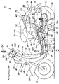
図1は本発明に係る自動二輪車の左側面図である。なお、図面は符号の向きに見るものとする。
自動二輪車10は、車体フレーム11と、車体フレーム11のヘッドパイプ11aに取付けたフロントフォーク12と、フロントフォーク12に取付けた前輪13と、フロントフォーク12に連結したハンドル14と、車体フレーム11の後部に上下スイング可能に取付けたユニットスイングエンジン15と、ユニットスイングエンジン15に取付けた後輪16と、ユニットスイングエンジン15の後端部を懸架したリヤクッションユニット17と、車体フレーム11の後部上部に取付けた収納ボックス18と、収納ボックス18の上に配置し開閉可能に取付けたシート19とを、主要構成とした自動二輪車である。FIG. 1 is a left side view of a motorcycle according to the present invention. The drawings are viewed in the direction of the reference numerals.
The
車体フレーム11は、ヘッドパイプ11aを一体成形したダイキャスト製フロントフレーム11Fと、ダイキャスト製リヤフレーム11Rとを、連結部11Cで連結した。
ユニットスイングエンジン15は、エンジン21と遠心クラッチ付きベルトコンバータ無段変速機22とからなる。エンジン21は、シリンダ部分を収納ボックス18と燃料タンク42との間に臨ませ、略水平方向に傾斜した水冷式4サイクルエンジンである。In the
The
更に自動二輪車10は、車体フレーム11をボディカバー30で覆ったものである。ボディカバー30は、ヘッドパイプ11aの前部を覆うフロントカバー31と、ヘッドパイプ11aを挟みフロントカバー31の後部を覆うとともに運転者の脚部前方を覆うレッグシールド32と、運転者の足を載せるステップフロア(低床式足載板)33と、ステップフロア33の外縁から下方へ延ばした左右一対のフロアサイドカバー34と、これらフロアサイドカバー34の下縁間を覆うアンダカバー35と、シート19下周りの前部を覆うシート下部カバー36と、シート19下後部と後輪16の上方を覆うリヤカバー37と、左右一対のサイドカバー38とからなる。 Furthermore, the
このような自動二輪車10は、レッグシールド32の部分にメインスイッチ(イグニッションキーシリンダ)41を配置し、ステップフロア33の下に燃料タンク42並びに燃料タンク42内に内蔵した燃料ポンプ43を配置し、車体フレーム11の後部上端部に図示せぬトレイを設けるとともに、このトレイにラジエータ用リザーブタンク44、バッテリ45並びに制御ユニット46を配置したものである。 In such a
図中、51はハンドルグリップ、52は左ブレーキレバー、53はメータパネル、54はミラー、55は左右一対に設けられるフロントウインカ、56Fは前側ハンドルカバー、56Rは後側ハンドルカバー、57はヘッドランプ、58はフロントカバー31内に設けられるホーン、59はフロントフォーク12と共に回動するフロントフェンダ、61は左右一対のエンジンハンガ、62はエンジン始動用キックペダル、63は車体左側に設けたエアクリーナ、64はキャブレータ、65はエンジン21のクランク軸21aの右端に設けたエンジン冷却用ラジエータ、66はエンジン用排気管、67は車体右側に設けた排気用マフラ、71はメインスタンド、72はリヤフェンダ、73はテールランプ、74はリヤウインカ、75はキャリア、Heはヘルメットである。 In the figure, 51 is a handle grip, 52 is a left brake lever, 53 is a meter panel, 54 is a mirror, 55 is a front turn signal provided in a pair of left and right, 56F is a front handle cover, 56R is a rear handle cover, and 57 is a headlamp. , 58 is a horn provided in the
図2は図1の2部拡大断面図であり、本発明の燃料ポンプケースを装備した燃料タンクの断面図を示す。
燃料ポンプケース80は、燃料ポンプ43本体に付属して燃料ポンプ43本体を燃料タンク42の所定個所に取付けるときに用いるケースである。そして、燃料ポンプ43の吐出口81からエンジン21(図1参照)へ向かう燃料の通路82を内蔵した燃料ポンプケース80において、燃料の通路82は、燃料ポンプの吐出口81に直交する燃料出口83を備え、且つ燃料ポンプの吐出口81から吐出した燃料が円滑に燃料出口83に向かうように傾斜したガイド面84を備えた。2 is an enlarged cross-sectional view of part 2 of FIG. 1, and shows a cross-sectional view of a fuel tank equipped with the fuel pump case of the present invention.
The
そして、燃料出口82に燃料供給路85を付設し、燃料供給路85の出口にエンジン側に向けて燃料パイプ87を取付けた。
また、燃料の通路82にリリーフ弁88に連通する燃料排出口89を設けた。
なお、91は燃料タンク42から燃料を吸入する吸入口、92はサンクションフィルター、93は燃料切れ検出ユニット、94は燃料切れ検出用フロートである。A
In addition, a
Note that 91 is an intake port for sucking fuel from the
次に、燃料ポンプケース80の取付け関係について説明する。
フロントフレーム11Fに燃料タンク42を取付け、燃料タンク42の上面に燃料ポンプケース80が嵌まるようにケース取付けブラケット96を設けた。
あらかじめ、燃料タンク42に燃料ポンプケース80を固定するために、ケース取付けブラケット96にサブブラケット97を介してボルト98を取付けた。Next, the attachment relationship of the
The
In advance, in order to fix the
そして、ケース取付けブラケット96に、燃料ポンプ本体43、リリーフ弁88を取付けた燃料ポンプケース80とシール部材99を嵌め、この燃料ポンプケース80の上に固定部材101を載せて、最後に、締付けナット102により燃料ポンプケース80を固定する。
燃料の通路82に、燃料の通路内圧が所定圧力を超えると開いて燃料を燃料タンク42に戻すリリーフ弁88を臨ませた。Then, the
A
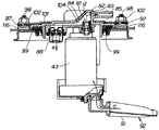
図3は図2の3矢視図であり、燃料タンク42(図2参照)に燃料ポンプケース80を嵌め、この燃料ポンプケース80の上に固定部材101を載せて、最後に、締付けナット102により燃料ポンプケース80を固定したことを示す。
燃料ポンプケース80の上に燃料の通路82を備え、燃料の通路82の燃料出口83に燃料供給路85を付設した。
103は燃料ポンプ43に電源を供給する電源供給コネクタである。FIG. 3 is a view taken in the direction of arrow 3 in FIG. 2. The
A
A
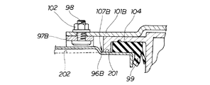
図4は図2の4部拡大図であり、燃料ポンプケース80の締付け構造について詳しく説明する。
燃料ポンプケース80を構成するフランジ部の縁105を燃料タンク42側に折曲げて折曲げ部106とし、この折曲げ部106の高さHを、シール部材99が所定のシール作用を発揮するシール部材厚さに合致させた。FIG. 4 is an enlarged view of part 4 of FIG. 2, and the tightening structure of the
The
前述のように、燃料タンク42の上側に燃料ポンプケース80が嵌まるようにケース取付けブラケット96を設け、ケース取付けブラケット96にサブブラケット97を介してボルト98を取付けた。 As described above, the
ケース取付けブラケット96の上面107にシール部材の下面108及びフランジ部の縁105を折曲げた折曲げ部106の縁105とを当接し、シール部材99の上面109にフランジ部の下面111を当接させ、このフランジ部の上面112に固定部材の下面113を当て、サブブラケットの鍔部114と固定部材101を、ボルト98と締付けナット102とで挟持して締付けることにより燃料タンク42に燃料ポンプケース80を固定する。 The
なお、サブブラケット97の穴部115にボルト98を差し込んだ後、サブブラケット97の脚部116をケース取付けブラケット96にあらかじめ固着するが、固着方法は例えば、スポット溶接、アーク溶接等の溶接手段により固着する。
図3に戻って、燃料ポンプケース80を固定するために設けたボルト98の個数を4つとしたが、所定のシール作用を得るための個数については4つに限定するものではなく任意の数に設定することができる。ボルト98のサイズについても、任意のサイズに設定可能とする。In addition, after inserting the
Returning to FIG. 3, the number of
図5は本発明に係る燃料ポンプケースの締付け作用図であり、ケース取付けブラケット96に燃料タンク42と一体化しフランジ部104にシール部材99を嵌めた燃料ポンプケース80を載せ、固定部材101を載せ、締付けナット102をボルト98に装着して、燃料ポンプケース80を締付け途中のフランジ部104とシール部材99とケース取付けブラケットの上面107の3者相互の位置関係を示す。 FIG. 5 is a diagram showing the tightening action of the fuel pump case according to the present invention. The
燃料ポンプケース80を締付け途中において、先ずシール部材99の下面108がケース取付けブラケット96の上面107に当接し、締付けナット102の締付けをすすめると、シール部材の下面108が当接したまま、フランジ部の折曲げ部106の縁105はブラケットの上面107に近づく。 In the middle of tightening the
図4に戻って、締付けナット102の締付けを更にすすめると、シール部材99の下面108がケース取付けブラケット96の上面107に当接したままつぶれ、ついには、フランジ部の折曲げ部106の縁105がブラケットの上面107に当接して締付けが完了する。 Returning to FIG. 4, when the tightening of the tightening
燃料タンク42側へ押圧してシール作用を発揮する燃料ポンプケース80のフランジ部104を折曲げ、折曲げたフランジ折曲げ部106の高さHを、シール部材99が所定のシール作用を発揮するようにシール部材厚さHに合致させた。
フランジ折曲げ部106の高さHをシール部材厚さHに合致させたので、フランジ折曲げ部106の高さの管理のみで所定のシール作用を容易に発揮させることができる。The
Since the height H of the flange
図6は本発明に係る燃料ポンプを装備した燃料ポンプケースの作用図であり、吸入口91からサンクションフィルター92を通じて矢印cのごとく燃料ポンプ43に入った燃料は、燃料ポンプの吐出口81から矢印dのごとく燃料の通路82に入り、吐出口81から燃料出口83に向かうように傾斜したガイド面84の作用により、燃料をより円滑に燃料出口83に流すことができる。そして、燃料の通路82の燃料圧力が所定圧力以上に上昇すると、この燃料はリリーフ弁88により矢印eのごとく流れることを示す。 FIG. 6 is an operation diagram of a fuel pump case equipped with the fuel pump according to the present invention. The fuel that has entered the
燃料ポンプの吐出口81から吐出した燃料は、燃料の通路82に傾斜させて配置したガイド面84にガイドされてゆるやかに向きを変え燃料供給管85に入る。
燃料はガイド面84によりゆるやかに向きを変え、円滑に流れ燃料供給管85に入るため、流れの乱れは少ない。The fuel discharged from the
The fuel gently changes its direction by the
また、リリーフ弁88を燃料ポンプケース80と一体化したので、リリーフ弁88関連の追加部品を不要にし、制約の多い燃料ポンプケース80廻りのスペースを節減することができる。 Further, since the
さらにまた、燃料ポンプの吐出口81から吐出した燃料が円滑に燃料出口83に向かうように傾斜させたガイド面84は、燃料ポンプケース80の壁面104を傾斜させることにより形成した。
燃料ポンプケース80の壁面104を傾斜させることによりガイド面84を形成したので、追加部材を準備すること無く燃料の通路82内の燃料を円滑に流すことができる。Furthermore, the
Since the
図7は図3の別実施例図であり、燃料ポンプケース80の上に固定部材101を載せて、締付けナット102により燃料ポンプケース80を固定したことを示す。
本図において、締付けナット102による締付け箇所を8箇所としたが、必要に応じて締付けナット102の個数を変更することも可能である。
また、ケース取付けブラケット96Bの上面107Bには、取付け穴に沿って下方に段差を持つ段差部201を備え、さらに水抜き通路202を備えた。
FIG. 7 is a diagram showing another embodiment of FIG. 3 and shows that the fixing
In this figure, the number of tightening
On the
図8は図4の別実施例図であり、燃料タンク42の上側に燃料ポンプケース80が嵌まるようにケース取付けブラケット96Bを設け、ケース取付けブラケット96Bにサブブラケット97Bを介してボルト98を取付けたことを示す。 FIG. 8 is a diagram showing another embodiment of FIG. 4, and a
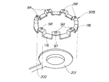
図9は本発明の別実施例に係るサブブラケットの矢視図であり、116はサブブラケット97Bの脚部、98はボルトを示す。
図に示すように、ブラケットの脚部116の間にあってボルト98の下方の一箇所に水抜き通路202を配置した。
別実施例によれば、燃料ポンプを低く配置することができることから、ステップフロア33をフラット形状にし易くなる。また、段差部201の水抜きも確実にできる。
9 is an arrow view of a sub-bracket according to another embodiment of the present invention, 116 legs of the sub-bracket 97B, 98 denotes a bolt.
As shown in the figure, a
According to another embodiment, since the fuel pump can be arranged low, the
尚、本発明に係るポンプケースのシール部材の材質は、ゴム系でも良いしプラスチック系でも良い。
また、シール部材の形状は、本実施の形態において2リップタイプとしたが、1リップタイプ及び複数リップタイプでも差し支えない。
更にまた、本発明の燃料ポンプケースは、実施の形態では燃料タンクに内蔵した自動二輪車に適用したが、三輪車にも適用可能であり、一般の車両に適用することは差し支えない。The material of the seal member of the pump case according to the present invention may be rubber or plastic.
In addition, the shape of the seal member is a two-lip type in the present embodiment, but a one-lip type or a plurality of lip types may be used.
Furthermore, although the fuel pump case of the present invention is applied to a motorcycle built in a fuel tank in the embodiment, it can also be applied to a tricycle and can be applied to a general vehicle.
本発明の燃料ポンプケースは、自動二輪車に好適である。 The fuel pump case of the present invention is suitable for a motorcycle.
42…燃料タンク、43…燃料ポンプ、80…燃料ポンプケース、82…燃料の通路、84…ガイド面、96…ケース取付けブラケット、97…サブブラケット、99…シール部材、101…固定部材、104…フランジ部、105…フランジ部の縁、106…折曲げ部。 42 ... Fuel tank, 43 ... Fuel pump, 80 ... Fuel pump case, 82 ... Fuel passage, 84 ... Guide surface, 96 ... Case mounting bracket, 97 ... Sub bracket, 99 ... Seal member, 101 ... Fixing member, 104 ... Flange part, 105 ... edge of flange part, 106 ... bent part.
Claims (5)
前記フランジ部の縁を前記燃料タンク側に折曲げて折曲げ部の縁とし、この折曲げ部の内側に、且つ、前記フランジ部と前記燃料タンク側の間に前記シール部材が配置され、前記折曲げ部の高さを、前記シール部材が所定のシール作用を発揮するシール部材厚さに合致させ、
前記シール部材および前記折曲げ部の縁を受けるブラケットを前記燃料タンク側に設け、
前記ブラケットに、前記フランジ部を前記燃料タンクの側へ押圧する板状の固定部材を取付け、
この固定部材と前記ブラケットとで前記フランジ部を挟持し前記折曲げ部の縁を前記ブラケットに当接させて固定することを特徴とする燃料ポンプ取付構造。 It includes a case which is used when mounting the fuel pump body supplied with the fuel pump body at a predetermined location of the fuel tank, to exert sealing action by pressing the flange portion of the case through a seal member to the fuel tank In the type of fuel pump mounting structure,
The edge of the flange portion is bent to the fuel tank side to form an edge of the bent portion, and the seal member is disposed inside the bent portion and between the flange portion and the fuel tank side, The height of the bent portion is matched to the thickness of the sealing member where the sealing member exhibits a predetermined sealing action,
A bracket for receiving an edge of the sealing member and the bent portion is provided on the fuel tank side ,
To the bracket, attaching the plate-shaped fixing member for pressing the flange portion to the side of the fuel tank,
A fuel pump mounting structure characterized in that the fixing member and the bracket sandwich the flange portion and fix the bent portion by contacting the edge of the bent portion with the bracket.
Priority Applications (3)
| Application Number | Priority Date | Filing Date | Title |
|---|---|---|---|
| JP2003379125A JP4295065B2 (en) | 2003-10-02 | 2003-10-02 | Fuel pump mounting structure |
| TW093128613A TWI257451B (en) | 2003-10-02 | 2004-09-21 | Fuel pump case |
| CN2004100959522A CN1605747B (en) | 2003-10-02 | 2004-09-30 | Fuel pump mounting structure |
Applications Claiming Priority (1)
| Application Number | Priority Date | Filing Date | Title |
|---|---|---|---|
| JP2003379125A JP4295065B2 (en) | 2003-10-02 | 2003-10-02 | Fuel pump mounting structure |
Publications (3)
| Publication Number | Publication Date |
|---|---|
| JP2005113892A JP2005113892A (en) | 2005-04-28 |
| JP2005113892A5 JP2005113892A5 (en) | 2006-11-16 |
| JP4295065B2 true JP4295065B2 (en) | 2009-07-15 |
Family
ID=34544489
Family Applications (1)
| Application Number | Title | Priority Date | Filing Date |
|---|---|---|---|
| JP2003379125A Expired - Fee Related JP4295065B2 (en) | 2003-10-02 | 2003-10-02 | Fuel pump mounting structure |
Country Status (3)
| Country | Link |
|---|---|
| JP (1) | JP4295065B2 (en) |
| CN (1) | CN1605747B (en) |
| TW (1) | TWI257451B (en) |
Families Citing this family (10)
| Publication number | Priority date | Publication date | Assignee | Title |
|---|---|---|---|---|
| JP4488362B2 (en) | 2005-11-01 | 2010-06-23 | 本田技研工業株式会社 | Fuel pump mounting structure |
| JP4755554B2 (en) * | 2005-11-22 | 2011-08-24 | 本田技研工業株式会社 | Scooter type fuel pump arrangement structure |
| ATE456505T1 (en) * | 2007-09-03 | 2010-02-15 | Yamaha Motor Res & Dev Europe Srl | FUEL TANK ARRANGEMENT FOR A MOTORCYCLE AND MOTORCYCLE EQUIPPED WITH SUCH A TANK ARRANGEMENT |
| DE102009003051A1 (en) * | 2009-05-13 | 2010-11-18 | Robert Bosch Gmbh | Method for filling a fuel system for motor vehicles |
| JP5358382B2 (en) * | 2009-09-30 | 2013-12-04 | 本田技研工業株式会社 | Fuel pump support structure |
| JP5123928B2 (en) * | 2009-12-22 | 2013-01-23 | 本田技研工業株式会社 | Fuel supply device |
| JP5664422B2 (en) * | 2011-04-11 | 2015-02-04 | スズキ株式会社 | Fuel pump mounting structure and motorcycle |
| CN103213635A (en) * | 2013-04-15 | 2013-07-24 | 江门市大长江集团有限公司 | Fuel tank cap and oil filler sealing structure assembly for motorcycle |
| JP6300276B2 (en) | 2014-12-15 | 2018-03-28 | 本田技研工業株式会社 | Fuel pump unit seal structure |
| CN216887242U (en) * | 2022-02-17 | 2022-07-05 | 上海峰飞航空科技有限公司 | Leak protection oil tank and unmanned aerial vehicle |
Family Cites Families (4)
| Publication number | Priority date | Publication date | Assignee | Title |
|---|---|---|---|---|
| JP3772630B2 (en) * | 2000-03-02 | 2006-05-10 | スズキ株式会社 | Motorcycle fuel tank equipment |
| JP4432194B2 (en) * | 2000-03-16 | 2010-03-17 | 株式会社デンソー | Engine fuel supply packing |
| JP3938473B2 (en) * | 2001-01-23 | 2007-06-27 | 本田技研工業株式会社 | Fuel pump tank mounting structure |
| JP4176456B2 (en) * | 2002-11-29 | 2008-11-05 | 本田技研工業株式会社 | Fuel system layout structure for motorcycles |
-
2003
- 2003-10-02 JP JP2003379125A patent/JP4295065B2/en not_active Expired - Fee Related
-
2004
- 2004-09-21 TW TW093128613A patent/TWI257451B/en not_active IP Right Cessation
- 2004-09-30 CN CN2004100959522A patent/CN1605747B/en not_active Expired - Fee Related
Also Published As
| Publication number | Publication date |
|---|---|
| TWI257451B (en) | 2006-07-01 |
| CN1605747B (en) | 2010-09-29 |
| CN1605747A (en) | 2005-04-13 |
| TW200513589A (en) | 2005-04-16 |
| JP2005113892A (en) | 2005-04-28 |
Similar Documents
| Publication | Publication Date | Title |
|---|---|---|
| CA2515966C (en) | Fuel tank mounting structure in saddleride type vehicle | |
| JP5627154B2 (en) | Straddle-type electric vehicle | |
| US6341792B1 (en) | Tank cover attachment structure for motorcycle | |
| JP4463639B2 (en) | Cooling structure for electric vehicles | |
| US7845446B2 (en) | Scooter type vehicle | |
| JP5926653B2 (en) | Storage structure of saddle-ride type vehicle | |
| EP2457813B1 (en) | Inner rack structure for saddle-ride type vehicle | |
| JP4295065B2 (en) | Fuel pump mounting structure | |
| JP4575335B2 (en) | Fuel tank | |
| US7581784B2 (en) | Front structure for vehicle | |
| AU2007201661A1 (en) | Vehicle instrument panel device | |
| JP4249345B2 (en) | Scooter type motorcycle air cleaner | |
| JP5719264B2 (en) | Canister layout for saddle riding type vehicles | |
| JP2008050006A (en) | Heat shielding structure of fuel tank for scooter type vehicle | |
| US7140462B2 (en) | Supplemental air cleaner for an all-terrain vehicle, and all-terrain vehicle incorporating same | |
| TWI764595B (en) | Straddled vehicle | |
| JP3901904B2 (en) | Intake chamber structure of motorcycle | |
| JP4015418B2 (en) | Scooter type motorcycle | |
| JPH10203453A (en) | Windscreen device for scooter type vehicle | |
| JP3594700B2 (en) | Motorcycle body cover | |
| JP3041820B2 (en) | Motorcycle and tricycle handle covers | |
| JPH07110625B2 (en) | Scooter type vehicle storage device | |
| TWI323762B (en) | ||
| JP2003205877A (en) | Storage box structure for scooter type motorcycle | |
| JP2716720B2 (en) | Motor cleaner air cleaner chamber mounting structure |
Legal Events
| Date | Code | Title | Description |
|---|---|---|---|
| A521 | Written amendment |
Free format text: JAPANESE INTERMEDIATE CODE: A523 Effective date: 20060929 |
|
| A621 | Written request for application examination |
Free format text: JAPANESE INTERMEDIATE CODE: A621 Effective date: 20060929 |
|
| A977 | Report on retrieval |
Free format text: JAPANESE INTERMEDIATE CODE: A971007 Effective date: 20080630 |
|
| A131 | Notification of reasons for refusal |
Free format text: JAPANESE INTERMEDIATE CODE: A131 Effective date: 20080708 |
|
| A521 | Written amendment |
Free format text: JAPANESE INTERMEDIATE CODE: A523 Effective date: 20080908 |
|
| A131 | Notification of reasons for refusal |
Free format text: JAPANESE INTERMEDIATE CODE: A131 Effective date: 20081210 |
|
| A521 | Written amendment |
Free format text: JAPANESE INTERMEDIATE CODE: A523 Effective date: 20090203 |
|
| TRDD | Decision of grant or rejection written | ||
| A01 | Written decision to grant a patent or to grant a registration (utility model) |
Free format text: JAPANESE INTERMEDIATE CODE: A01 Effective date: 20090407 |
|
| A01 | Written decision to grant a patent or to grant a registration (utility model) |
Free format text: JAPANESE INTERMEDIATE CODE: A01 |
|
| A61 | First payment of annual fees (during grant procedure) |
Free format text: JAPANESE INTERMEDIATE CODE: A61 Effective date: 20090409 |
|
| FPAY | Renewal fee payment (event date is renewal date of database) |
Free format text: PAYMENT UNTIL: 20120417 Year of fee payment: 3 |
|
| R150 | Certificate of patent or registration of utility model |
Free format text: JAPANESE INTERMEDIATE CODE: R150 |
|
| FPAY | Renewal fee payment (event date is renewal date of database) |
Free format text: PAYMENT UNTIL: 20130417 Year of fee payment: 4 |
|
| FPAY | Renewal fee payment (event date is renewal date of database) |
Free format text: PAYMENT UNTIL: 20130417 Year of fee payment: 4 |
|
| FPAY | Renewal fee payment (event date is renewal date of database) |
Free format text: PAYMENT UNTIL: 20140417 Year of fee payment: 5 |
|
| LAPS | Cancellation because of no payment of annual fees |