JP3772630B2 - Motorcycle fuel tank equipment - Google Patents
Motorcycle fuel tank equipment Download PDFInfo
- Publication number
- JP3772630B2 JP3772630B2 JP2000057686A JP2000057686A JP3772630B2 JP 3772630 B2 JP3772630 B2 JP 3772630B2 JP 2000057686 A JP2000057686 A JP 2000057686A JP 2000057686 A JP2000057686 A JP 2000057686A JP 3772630 B2 JP3772630 B2 JP 3772630B2
- Authority
- JP
- Japan
- Prior art keywords
- pump
- fuel
- mounting bracket
- pump mounting
- tank
- Prior art date
- Legal status (The legal status is an assumption and is not a legal conclusion. Google has not performed a legal analysis and makes no representation as to the accuracy of the status listed.)
- Expired - Fee Related
Links
Images


Classifications
-
- B—PERFORMING OPERATIONS; TRANSPORTING
- B62—LAND VEHICLES FOR TRAVELLING OTHERWISE THAN ON RAILS
- B62J—CYCLE SADDLES OR SEATS; AUXILIARY DEVICES OR ACCESSORIES SPECIALLY ADAPTED TO CYCLES AND NOT OTHERWISE PROVIDED FOR, e.g. ARTICLE CARRIERS OR CYCLE PROTECTORS
- B62J35/00—Fuel tanks specially adapted for motorcycles or engine-assisted cycles; Arrangements thereof
-
- Y—GENERAL TAGGING OF NEW TECHNOLOGICAL DEVELOPMENTS; GENERAL TAGGING OF CROSS-SECTIONAL TECHNOLOGIES SPANNING OVER SEVERAL SECTIONS OF THE IPC; TECHNICAL SUBJECTS COVERED BY FORMER USPC CROSS-REFERENCE ART COLLECTIONS [XRACs] AND DIGESTS
- Y10—TECHNICAL SUBJECTS COVERED BY FORMER USPC
- Y10T—TECHNICAL SUBJECTS COVERED BY FORMER US CLASSIFICATION
- Y10T137/00—Fluid handling
- Y10T137/8593—Systems
- Y10T137/85978—With pump
- Y10T137/86035—Combined with fluid receiver
- Y10T137/86043—Reserve or surge receiver
-
- Y—GENERAL TAGGING OF NEW TECHNOLOGICAL DEVELOPMENTS; GENERAL TAGGING OF CROSS-SECTIONAL TECHNOLOGIES SPANNING OVER SEVERAL SECTIONS OF THE IPC; TECHNICAL SUBJECTS COVERED BY FORMER USPC CROSS-REFERENCE ART COLLECTIONS [XRACs] AND DIGESTS
- Y10—TECHNICAL SUBJECTS COVERED BY FORMER USPC
- Y10T—TECHNICAL SUBJECTS COVERED BY FORMER US CLASSIFICATION
- Y10T137/00—Fluid handling
- Y10T137/8593—Systems
- Y10T137/86187—Plural tanks or compartments connected for serial flow
- Y10T137/86212—Plural compartments formed by baffles
Landscapes
- Engineering & Computer Science (AREA)
- Mechanical Engineering (AREA)
- Cooling, Air Intake And Gas Exhaust, And Fuel Tank Arrangements In Propulsion Units (AREA)
Description
【0001】
【発明の属する技術分野】
本発明は、タンク本体の内部に燃料ポンプが設置された自動二輪車の燃料タンク装置に関するものである。
【0002】
【従来の技術】
近年、自動二輪車についても排気ガスの低公害化や省燃費化が必須とされ、これに応じて燃料噴射装置による燃料供給方式が普及しつつある。このような自動二輪車では、エンジン側に設けられた燃料噴射装置に燃料タンク内の燃料を圧送してやる必要があり、燃料タンクに燃料ポンプが付設されている。図4は、このような燃料タンク装置の従来例を示すものである。
【0003】
ここに示すように、タンク本体101内部の底面101aの最低部付近に燃料ポンプ102が設置され、その吸入部103が底面101aよりもやや高い位置にある。燃料ポンプ102が作動すると、タンク本体101内部の燃料が吸入部103から吸入されて所定圧に加圧され、高圧な燃料が燃料ホース104を経て燃料噴射装置105に供給される。
【0004】
燃料ポンプ102の吸入部103がタンク本体101の底面101aよりも上方に置かれる理由は、燃料が切れた時でもタンク本体101の内部に少量の燃料(残留燃料)が残るようにして燃料ポンプ102の過回転による過熱を燃料により冷却可能にするためである。
【0005】
【発明が解決しようとする課題】
しかしながら、このように燃料ポンプ102の吸入部103がタンク本体101の底面101aよりも高い位置にあることから、例えばタンク本体101内の燃料が残り少ない時に自動二輪車が急減速した際、タンク本体101内の燃料が前方に片寄って燃料ポンプ102の吸入部103が燃料液面上に露出し、燃料ポンプ102が空気を吸入して一時的な燃料切れが起こり得るという問題がある。
【0006】
本発明に係る自動二輪車の燃料タンク装置は、上記問題点を解決するべく発明されたものであり、その目的は、燃料残量が少なくなった時における一時的な燃料切れの発生を防止するとともに、タンク本体と燃料ポンプ間の組付性およびシール性を向上させ、併せて燃料ポンプ関連の部品点数と組立工数を削減することにある。
【0007】
【課題を解決するための手段】
上記目的を達成するため、本発明に係る自動二輪車の燃料タンク装置は、請求項1に記載したように、タンク本体の底面に燃料ポンプが設置された自動二輪車の燃料タンク装置において、前記タンク本体の底面に形成した貫通穴の内周に、ポンプ取付ブラケットを下方から嵌合して液密に固着する一方、前記タンク本体の底面に固着されたポンプ取付ブラケットの下面に、有底椀状のポンプケースの上面を液密に取り付け、前記ポンプ取付ブラケットは、その中心にポンプ取付穴が形成され、かつこのポンプ取付穴を囲むようにポンプ取付ブラケット上面側から上方に突出する略筒状の囲い部を一体に形成し、前記ポンプ取付穴および囲い部を通して前記燃料ポンプをポンプケースに一体的に設け、前記ポンプケースの内部空間をタンク本体の内部空間に上記ポンプ取付穴および囲い部内を経て連通させるとともに、燃料ポンプの吸入部をポンプケースの内部に配置し、この吸入部をタンク本体の底面とポンプケースの底面との間の高さに位置付けたことを特徴とする。
【0008】
この構成において、タンク本体内部の燃料は燃料ポンプのポンプケース内に流れて吸入部に吸入される。タンク本体内部の燃料が少なくなると、ポンプケース内の燃料液面の高さが吸入部を下回った時点で燃料の吸入がストップするが、吸入部よりも下方に残る残留燃料により燃料ポンプが冷却されて過熱が防止される。そして、燃料が残り少ない時に自動二輪車が急減速してタンク本体内部の燃料が前方に片寄っても、ポンプケース内に溜まる残留燃料の液面が燃料ポンプの吸入部よりも上方に保たれるので一時的な燃料切れが起きない。
【0009】
また、本発明に係る自動二輪車の燃料タンク装置は、前記ポンプ取付ブラケットのポンプ取付穴の周囲に、上方に延びる略筒状の囲い部を一体形成した。この囲い部の設置により、前述のようにタンク本体内部の燃料が片寄った際に、燃料ポンプの吸入部に対する残留燃料の液面が高くなるため、一時的な燃料切れが一層確実に防止される。また、囲い部を別部品として設ける必要がなくなり、燃料ポンプ関連の部品点数と組立工数が削減される。
【0010】
さらに、本発明に係る自動二輪車の燃料タンク装置は、前記タンク本体の底面に別体のポンプ取付ブラケットを液密に固着し、このポンプ取付ブラケットに前記ポンプ取付穴を形成し、ポンプ取付ブラケットの下面と前記ポンプケースの上面を液密に合わせて締結固定した。こうすることにより、タンク本体と燃料ポンプとの間における組付性およびシール性が向上する。
【0012】
【発明の実施の形態】
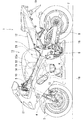
以下、本発明の一実施形態について図面を参照しながら説明する。図1は、本発明に係る燃料タンク装置が適用された自動二輪車の一例を示す左側面図である。
【0013】
この自動二輪車1は、その車体フレーム2の前頭部に前輪3を支持するフロントフォーク4がハンドルバー5等と共に左右回動自在に軸支され、車体フレーム2の中央下部にて車幅方向に軸支されたピボット軸6には後輪7を支持するスイングアーム8が上下回動可能に軸支されている。
【0014】
車体フレーム2の前半部分は左右一対の太いメインパイプ10により構成され、その上部に燃料タンク装置11が設けられ、燃料タンク装置11の後方に着座シート12が載置されている。燃料タンク装置11の下方には例えば直列4気筒の4サイクルDOHC水冷エンジン13が搭載され、エンジン13の上部に横4連の燃料噴射装置14が接続され、その上部に箱状のエアクリーナー15が接続されている。エンジン13の出力はチェーン16により後輪7に伝達される。
【0015】
また、エンジン13の前面から延出する排気管18がエンジン13の下面を回って後方に延び、排気マフラー19に繋がっている。自動二輪車1の車体前半部は流線形のカウリング21に覆われており、エンジン13や燃料噴射装置14、エアクリーナー15、排気管18等は外部に対して隠蔽される。
【0016】
図2にも示すように、燃料タンク装置11は、タンク本体22の底面22a後部に燃料ポンプ23が設置された構成であり、タンク本体22の前部下面には上方に凹む凹部22a(図1参照)が形成され、ここにエアクリーナー15が収容される。燃料ポンプ23の下部(後述するポンプケース37)はタンク本体22の底面22a後部から下方に突出(露出)し、ここに設けられたユニオン24と燃料噴射装置14との間が燃料ホース25で接続される。
【0017】
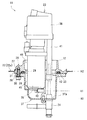
図3に拡大して示すように、タンク本体22の底面22a後部には円形の貫通穴27が形成され、その内周に下方から嵌合される形で別体のポンプ取付ブラケット28が溶接等により固着され、このポンプ取付ブラケット28に開設された円形のポンプ取付穴29に燃料ポンプ23がスクリュー部材30で取り付けられる構造である。
【0018】
ポンプ取付ブラケット28は平面視で略環状であり、中心に上記ポンプ取付穴29が形成され、その周囲に複数のネジ孔31が下方から形成されている(例えば5箇所)。また、ポンプ取付ブラケット28の上面側にはポンプ取付穴29の外周を囲むように上方に延びる短い筒状の囲い部32が一体に形成され、ポンプ取付ブラケット28の下面側かつポンプ取付穴29の直ぐ外周には環状のシール溝33が刻設されている。
【0019】
一方、燃料ポンプ23は、ポンプ本体35の上にフィルター部36が搭載され、ポンプ本体35の下部にはポンプケース37が一体的に設けられ、このポンプケース37が燃料ポンプ23全体をタンク本体22(ポンプ取付ブラケット28)に取り付ける取付ブラケットを兼ねている。ポンプケース37は有底椀状に形成され、その上部に形成された平板状の取付フランジ38に、ポンプ取付ブラケット28のネジ孔31に整合する複数のスクリュー孔39が形成されている。
【0020】
ポンプ本体35の下部に設けられている吸入部40はポンプケース37の内部にあり、その高さH1がタンク本体22の底面22aの高さH2とポンプケース37の底面37aの高さH3との間に、好ましくはややH3寄りになるように設定されている。また、フィルター部36から下方に延びる吐出管41がポンプケース37に設けられた前述のユニオン24に繋がる。
【0021】
ポンプ取付ブラケット28のシール溝33には耐燃料性のあるゴム製のシールリング43が嵌装され、ポンプケース37の取付フランジ38がポンプ取付ブラケット28の下面に合わせられ、複数のスクリュー部材30が取付フランジ38のスクリュー孔39に挿通されてポンプ取付ブラケット28のネジ孔31に締結される。これにより、ポンプケース37(取付フランジ38)の上面がポンプ取付ブラケット28の下面に固定され、燃料ポンプ23全体がタンク本体22に固定される。シールリング43はポンプ取付ブラケット28とポンプケース37間の液密性を保つ。
【0022】
このように、タンク本体22の底面22a(貫通穴27)に別体のポンプ取付ブラケット28を固着し、このポンプ取付ブラケット28の下面にポンプケース37を複数のスクリュー部材30で締結固定する構造としたことにより、例えばタンク本体22の底面22aに燃料ポンプ23のポンプケース37を直接締結固定した場合に比べてタンク本体22と燃料ポンプ23との間の組付性やシール性を格段に向上させることができ、信頼性も高められる。
【0023】
ところで、燃料ポンプ23のポンプ本体35と、ポンプケース37の内側面およびポンプ取付ブラケット28のポンプ取付穴29ならびに囲い部32との間には空隙45があり、この空隙45によりポンプケース37の内部空間がポンプ取付穴29を経てタンク本体22の内部空間に連通しており、タンク本体22に注入された燃料(非図示)がポンプ取付穴29を通ってポンプケース37内に流れ込むようになっている。
【0024】
このように構成された燃料タンク装置11において、燃料ポンプ23が作動すると、タンク本体22内からポンプ取付穴29を経てポンプケース37内に流れ込んだ燃料が吸入部40に吸入され、吸入された燃料はポンプ本体35により所定圧まで加圧されてからフィルター部36により濾過され、吐出管41からユニオン24と燃料ホース25を経て燃料噴射装置14に供給される。
【0025】
例えば、タンク本体22内部の燃料が少なくなった時に自動二輪車1が急減速すると、タンク本体22内部の燃料は慣性力により前方に片寄るが、ポンプケース37内に満ちている燃料はタンク本体22の底面22aよりも低位置にあるため前方に流動せずにポンプケース37内にとどまり、その液面が燃料ポンプ23の吸入部40よりも上方に保たれる。したがって、一時的な燃料切れが起こらない。
【0026】
このようにポンプケース37内に残留する残留燃料の量は、ポンプ取付穴29の周囲に設けられた囲い部32によって大幅に増量され、燃料ポンプ23の吸入部40に対する残留燃料の液面が高くなるため、例えば急激な加減速が繰り返されるような運転状況下においても一時的な燃料切れを確実に防止することができる。なお、囲い部32をポンプ取付ブラケット28に一体形成したことにより、囲い部32を別部品として設ける必要がなくなるため、燃料ポンプ23の関連部品点数や組立工数を削減することができる。
【0027】
また、タンク本体22内部の燃料が一層少なくなり、ポンプケース37内の燃料液面の高さが吸入部40の高さH1を下回ると燃料の吸入はストップするが、ポンプケース37内には吸入部40よりも下方に少量の燃料が残留し、この残留燃料によりポンプ本体35が冷却されるため、ポンプ本体35の過回転による過熱が防止される。
【0028】
【発明の効果】
本発明に係る自動二輪車の燃料タンク装置は、タンク本体の底面に形成した貫通穴の内周に、ポンプ取付ブラケットを下方から嵌合して液密に固着する一方、前記タンク本体の底面に固着されたポンプ取付ブラケットの下面に、有底椀状のポンプケースの上面を液密に取り付け、前記ポンプ取付ブラケットは、その中心にポンプ取付穴が形成され、かつこのポンプ取付穴を囲むようにポンプ取付ブラケット上面側から上方に突出する略筒状の囲い部を一体に形成し、前記ポンプ取付穴および囲い部を通して前記燃料ポンプをポンプケースに一体的に設け、前記ポンプケースの内部空間をタンク本体の内部空間に上記ポンプ取付穴および囲い部内を経て連通させるとともに、燃料ポンプの吸入部をポンプケースの内部に配置し、この吸入部をタンク本体の底面とポンプケースの底面との間の高さに位置付けたことを特徴とするものであり、これによればタンク本体内部で残り少なくなった燃料が片寄っても、略筒状の囲い部を含めたポンプケース内に残留燃料を確保でき、燃料ポンプの吸入部が燃料液面上に露出して一時的な燃料切れが発生することを有効に防止することができる。
【0029】
また、本発明に係る自動二輪車の燃料タンク装置は、ポンプ取付穴の周囲に上方に突出する略筒状の囲い部をポンプ取付ブラケットと一体に設けたため、タンク本体内部の燃料が片寄った際における燃料ポンプの吸入部に対する残留燃料の液面を高くし、一時的な燃料切れの発生を一層確実に防止することができる。また、囲い部を別部品として設ける必要がなくなり、燃料ポンプ関連の部品点数と組立工数が削減される。
【図面の簡単な説明】
【図1】本発明に係る燃料タンク装置が適用された自動二輪車の一例を示す左側面図。
【図2】燃料タンク装置を拡大した左側面図。
【図3】本発明の一実施形態を示すタンク本体底面とポンプ取付ブラケットと燃料ポンプの拡大縦断面図。
【図4】従来の技術を示す燃料タンク装置の拡大左側面図。
【符号の説明】
1 自動二輪車
11 燃料タンク装置
14 燃料噴射装置
22 タンク本体
22a タンク本体の底面
23 燃料ポンプ
28 ポンプ取付ブラケット
29 ポンプ取付穴
30 スクリュー部材
32 囲い部
37 ポンプケース
37a ポンプケースの底面
40 吸入部
43 シールリング
45 空隙[0001]
BACKGROUND OF THE INVENTION
The present invention relates to a fuel tank apparatus for a motorcycle in which a fuel pump is installed inside a tank body.
[0002]
[Prior art]
2. Description of the Related Art In recent years, it has become essential for motorcycles to reduce exhaust gas pollution and to reduce fuel consumption, and fuel supply systems using fuel injection devices are becoming increasingly popular. In such a motorcycle, it is necessary to pump the fuel in the fuel tank to a fuel injection device provided on the engine side, and a fuel pump is attached to the fuel tank. FIG. 4 shows a conventional example of such a fuel tank apparatus.
[0003]
As shown here, the
[0004]
The reason why the
[0005]
[Problems to be solved by the invention]
However, since the
[0006]
The motorcycle fuel tank device according to the present invention was invented to solve the above-mentioned problems, and its purpose is to prevent the occurrence of temporary fuel shortage when the remaining fuel amount is low. It is to improve the assembling property and the sealing property between the tank main body and the fuel pump, and to reduce the number of parts and assembly man-hours related to the fuel pump.
[0007]
[Means for Solving the Problems]
In order to achieve the above object, a fuel tank apparatus for a motorcycle according to the present invention is the fuel tank apparatus for a motorcycle in which a fuel pump is installed on the bottom surface of the tank body. of the inner periphery of the through hole formed in the bottom surface, while secured in a liquid-tight fitted the pump mounting brackets from below the lower surface of the pump mounting bracket which is secured to the bottom surface of the tank body, a bottomed bowl-shaped The top surface of the pump case is liquid-tightly attached, and the pump mounting bracket has a substantially cylindrical enclosure that has a pump mounting hole at its center and projects upward from the top surface of the pump mounting bracket so as to surround the pump mounting hole. part of integrally formed, provided integrally with the fuel pump to the pump casing through the pump mounting hole and enclosure, the tank main body internal space of the pump case With communicating via an internal space in the pump mounting hole and the enclosure portion, arranged suction portion of the fuel pump inside the pump casing, the suction unit at a height between the bottom surface of the bottom surface and the pump casing of the tank body It is characterized by positioning.
[0008]
In this configuration, the fuel inside the tank body flows into the pump case of the fuel pump and is sucked into the suction portion. When the fuel inside the tank body decreases, the fuel suction stops when the fuel level in the pump case falls below the suction part, but the fuel pump is cooled by the residual fuel remaining below the suction part. This prevents overheating. And even if the motorcycle decelerates suddenly when the fuel is low and the fuel inside the tank body is displaced forward, the liquid level of the residual fuel that remains in the pump case is kept above the intake part of the fuel pump. No fuel shortage occurs.
[0009]
In the fuel tank device for a motorcycle according to the present invention, a substantially cylindrical enclosure extending upward is integrally formed around the pump mounting hole of the pump mounting bracket. By installing this enclosure, when the fuel inside the tank body is offset as described above, the liquid level of the residual fuel with respect to the suction portion of the fuel pump becomes higher, so that temporary fuel shortage can be prevented more reliably. . Moreover, it is not necessary to provide the enclosure as a separate part, and the number of parts related to the fuel pump and the number of assembly steps are reduced.
[0010]
Further, in the fuel tank device for a motorcycle according to the present invention, a separate pump mounting bracket is liquid-tightly fixed to the bottom surface of the tank body , the pump mounting hole is formed in the pump mounting bracket, and the pump mounting bracket The lower surface and the upper surface of the pump case were fastened together in a liquid-tight manner. By doing so, the assembling property and the sealing property between the tank body and the fuel pump are improved.
[0012]
DETAILED DESCRIPTION OF THE INVENTION
Hereinafter, an embodiment of the present invention will be described with reference to the drawings. FIG. 1 is a left side view showing an example of a motorcycle to which a fuel tank device according to the present invention is applied.
[0013]
In the motorcycle 1, a front fork 4 that supports a
[0014]
The front half portion of the
[0015]
Further, an
[0016]
As shown in FIG. 2, the
[0017]
As shown in FIG. 3 in an enlarged manner, a circular through
[0018]
The
[0019]
On the other hand, the
[0020]
The
[0021]
A fuel-resistant
[0022]
As described above, a separate
[0023]
By the way, there is a
[0024]
In the
[0025]
For example, when the motorcycle 1 suddenly decelerates when the fuel in the tank
[0026]
In this way, the amount of residual fuel remaining in the
[0027]
In addition, when the fuel in the
[0028]
【The invention's effect】
The fuel tank apparatus for a motorcycle according to the present invention, the inner periphery of the through hole formed in the bottom surface of the tank body, while secured in a liquid-tight fitted the pump mounting brackets from below, fixed to a bottom surface of the tank body The upper surface of a bottomed bowl-shaped pump case is liquid-tightly attached to the lower surface of the pump mounting bracket, and the pump mounting bracket has a pump mounting hole formed at the center thereof and surrounds the pump mounting hole. A substantially cylindrical enclosure projecting upward from the upper surface of the mounting bracket is integrally formed, and the fuel pump is integrally provided in the pump case through the pump mounting hole and the enclosure, and the internal space of the pump case is defined as a tank body. motor with communicating via the pump mounting hole and the enclosure unit in the internal space, arranged suction portion of the fuel pump inside the pump casing, the suction portion of the Which is characterized in that positioned at a height between the bottom surface of the click body bottom surface and the pump casing, even if offset is scarce since the fuel inside the tank body according to a substantially cylindrical enclosure It is possible to ensure the residual fuel in the pump case including the fuel, and to effectively prevent the fuel pump suction portion from being exposed on the fuel liquid level and causing a temporary fuel shortage.
[0029]
Further, the fuel tank device for a motorcycle according to the present invention is provided with a substantially cylindrical surrounding portion that protrudes upward around the pump mounting hole integrally with the pump mounting bracket. The liquid level of the residual fuel with respect to the suction part of the fuel pump can be increased, and the occurrence of temporary fuel shortage can be more reliably prevented. Moreover, it is not necessary to provide the enclosure as a separate part, and the number of parts related to the fuel pump and the number of assembly steps are reduced.
[Brief description of the drawings]
FIG. 1 is a left side view showing an example of a motorcycle to which a fuel tank device according to the present invention is applied.
FIG. 2 is an enlarged left side view of the fuel tank device.
FIG. 3 is an enlarged vertical sectional view of a tank body bottom face, a pump mounting bracket, and a fuel pump showing an embodiment of the present invention.
FIG. 4 is an enlarged left side view of a fuel tank device showing a conventional technique.
[Explanation of symbols]
DESCRIPTION OF SYMBOLS 1
Claims (1)
前記タンク本体の底面に形成した貫通穴の内周に、ポンプ取付ブラケットを下方から嵌合して液密に固着する一方、
前記タンク本体の底面に固着されたポンプ取付ブラケットの下面に、有底椀状のポンプケースの上面を液密に取り付け、
前記ポンプ取付ブラケットは、その中心にポンプ取付穴が形成され、かつこのポンプ取付穴を囲むようにポンプ取付ブラケット上面側から上方に突出する略筒状の囲い部を一体に形成し、
前記ポンプ取付穴および囲い部を通して前記燃料ポンプをポンプケースに一体的に設け、
前記ポンプケースの内部空間をタンク本体の内部空間に上記ポンプ取付穴および囲い部内を経て連通させるとともに、燃料ポンプの吸入部をポンプケースの内部に配置し、
この吸入部をタンク本体の底面とポンプケースの底面との間の高さに位置付けたことを特徴とする自動二輪車の燃料タンク装置。In a motorcycle fuel tank device in which a fuel pump is installed on the bottom of the tank body,
While fitting the pump mounting bracket from below to the inner periphery of the through hole formed in the bottom surface of the tank body ,
On the bottom surface of the pump mounting bracket fixed to the bottom surface of the tank body, the top surface of the bottomed bowl-shaped pump case is liquid-tightly attached,
The pump mounting bracket is integrally formed with a substantially cylindrical enclosure projecting upward from the top surface of the pump mounting bracket so that a pump mounting hole is formed at the center of the pump mounting bracket and surrounding the pump mounting hole.
The fuel pump is integrally provided in the pump case through the pump mounting hole and the enclosure,
Together to communicate with the interior space through the pump mounting hole and the enclosure portion of the tank main body internal space of the pump case, to place the suction portion of the fuel pump inside the pump casing,
A fuel tank device for a motorcycle, wherein the suction portion is positioned at a height between the bottom surface of the tank body and the bottom surface of the pump case.
Priority Applications (3)
| Application Number | Priority Date | Filing Date | Title |
|---|---|---|---|
| JP2000057686A JP3772630B2 (en) | 2000-03-02 | 2000-03-02 | Motorcycle fuel tank equipment |
| DE10109865A DE10109865B4 (en) | 2000-03-02 | 2001-03-01 | Fuel tank for motorcycle |
| US09/796,428 US6401750B2 (en) | 2000-03-02 | 2001-03-02 | Fuel tank unit of motorcycle |
Applications Claiming Priority (1)
| Application Number | Priority Date | Filing Date | Title |
|---|---|---|---|
| JP2000057686A JP3772630B2 (en) | 2000-03-02 | 2000-03-02 | Motorcycle fuel tank equipment |
Publications (2)
| Publication Number | Publication Date |
|---|---|
| JP2001247071A JP2001247071A (en) | 2001-09-11 |
| JP3772630B2 true JP3772630B2 (en) | 2006-05-10 |
Family
ID=18578426
Family Applications (1)
| Application Number | Title | Priority Date | Filing Date |
|---|---|---|---|
| JP2000057686A Expired - Fee Related JP3772630B2 (en) | 2000-03-02 | 2000-03-02 | Motorcycle fuel tank equipment |
Country Status (3)
| Country | Link |
|---|---|
| US (1) | US6401750B2 (en) |
| JP (1) | JP3772630B2 (en) |
| DE (1) | DE10109865B4 (en) |
Families Citing this family (40)
| Publication number | Priority date | Publication date | Assignee | Title |
|---|---|---|---|---|
| JP3889214B2 (en) * | 2000-09-29 | 2007-03-07 | 本田技研工業株式会社 | Vehicle fuel supply system |
| JP3879392B2 (en) * | 2000-11-29 | 2007-02-14 | スズキ株式会社 | Motorcycle fuel tank |
| JP3938473B2 (en) * | 2001-01-23 | 2007-06-27 | 本田技研工業株式会社 | Fuel pump tank mounting structure |
| US7422243B2 (en) * | 2003-07-29 | 2008-09-09 | Honda Motor Co., Ltd. | Structure of fuel pump installation area for two-wheeled vehicle |
| US6907865B1 (en) * | 2003-08-05 | 2005-06-21 | Walbro Engine Management, L.L.C. | Fuel tank assembly |
| JP4367913B2 (en) * | 2003-09-30 | 2009-11-18 | 本田技研工業株式会社 | Motorcycle fuel tank structure |
| JP4295065B2 (en) * | 2003-10-02 | 2009-07-15 | 本田技研工業株式会社 | Fuel pump mounting structure |
| JP4363566B2 (en) * | 2003-12-12 | 2009-11-11 | 本田技研工業株式会社 | Fuel supply device |
| JP4316390B2 (en) * | 2004-01-09 | 2009-08-19 | 本田技研工業株式会社 | Rider riding four-wheeled vehicle for rough terrain |
| US7992901B2 (en) * | 2004-01-27 | 2011-08-09 | Yamaha Hatsudoki Kabushiki Kaisha | Straddling type of vehicle |
| JP4388856B2 (en) * | 2004-06-04 | 2009-12-24 | 本田技研工業株式会社 | Motorcycle fuel tank |
| JP2006131028A (en) * | 2004-11-04 | 2006-05-25 | Aisan Ind Co Ltd | Fuel tank structure of motorcycle |
| US20080169033A1 (en) * | 2005-03-14 | 2008-07-17 | Inergy Auto. Systems Research (Societe Anonyme) | Fuel Tank With Low Profile Fuel Reservoir |
| JP2006257980A (en) * | 2005-03-17 | 2006-09-28 | Keihin Corp | In-line fuel supply device in fuel injection device |
| JP2007137406A (en) * | 2005-10-20 | 2007-06-07 | Yamaha Motor Co Ltd | Motorcycle fuel supply device and motorcycle |
| JP2007118627A (en) * | 2005-10-24 | 2007-05-17 | Yamaha Motor Co Ltd | Fuel tank assembly and straddle-type vehicle equipped with the fuel tank assembly |
| JP4563920B2 (en) * | 2005-10-31 | 2010-10-20 | 本田技研工業株式会社 | Fuel supply device |
| US7275523B2 (en) * | 2005-11-22 | 2007-10-02 | Keihin Corporation | Fuel supply unit in fuel tank for motorcycle |
| JP4711854B2 (en) * | 2006-02-27 | 2011-06-29 | 株式会社ケーヒン | Fuel supply system for motorcycles |
| JP4785576B2 (en) * | 2006-03-17 | 2011-10-05 | 株式会社ケーヒン | Fuel supply system for motorcycles |
| JP4725398B2 (en) * | 2006-04-12 | 2011-07-13 | スズキ株式会社 | Motorcycle fuel tank |
| JP5030485B2 (en) * | 2006-06-26 | 2012-09-19 | ヤマハ発動機株式会社 | Saddle riding vehicle |
| EP1953379B1 (en) * | 2007-02-01 | 2012-12-19 | Yamaha Hatsudoki Kabushiki Kaisha | Vehicle |
| USD595633S1 (en) | 2007-03-08 | 2009-07-07 | Stonie Todd Channel | Fuel tank and air passage assembly |
| JP2008230492A (en) * | 2007-03-22 | 2008-10-02 | Suzuki Motor Corp | Motorcycle fuel supply system |
| JP4916366B2 (en) * | 2007-04-06 | 2012-04-11 | 三菱電機株式会社 | Vehicle fuel supply system |
| US20080314670A1 (en) * | 2007-06-20 | 2008-12-25 | Buell Motorcycle Company | Fuel pump mounting for a motorcycle |
| US20090000844A1 (en) * | 2007-06-27 | 2009-01-01 | Jesus Castillo | Fuel module with quick disconnect cover for easy filter replacement |
| JP5235089B2 (en) * | 2008-03-27 | 2013-07-10 | 本田技研工業株式会社 | Fuel pump mounting structure |
| JP2010031774A (en) * | 2008-07-30 | 2010-02-12 | Mikuni Corp | Fuel supply system |
| JP5352008B2 (en) * | 2010-07-30 | 2013-11-27 | 本田技研工業株式会社 | Vehicle fuel tank assembly |
| JP5530293B2 (en) * | 2010-07-30 | 2014-06-25 | 本田技研工業株式会社 | Motorcycle |
| JP5520171B2 (en) * | 2010-09-14 | 2014-06-11 | 本田技研工業株式会社 | Fuel pump mounting device for saddle riding type vehicles |
| US8134469B2 (en) | 2010-10-27 | 2012-03-13 | Ford Global Technologies, Llc | Wireless fuel level sensor for a vehicle fuel tank |
| JP5996257B2 (en) * | 2011-12-15 | 2016-09-21 | 本田技研工業株式会社 | Saddle riding |
| JP2015068312A (en) * | 2013-09-30 | 2015-04-13 | 本田技研工業株式会社 | Fuel pump attachment structure |
| JP6645330B2 (en) * | 2016-04-13 | 2020-02-14 | スズキ株式会社 | Motorcycle fuel tank device |
| JP6993254B2 (en) * | 2018-02-07 | 2022-01-13 | 本田技研工業株式会社 | Saddle-type vehicle |
| JP2022522261A (en) * | 2019-02-28 | 2022-04-15 | プラスチック・オムニウム・アドヴァンスド・イノベーション・アンド・リサーチ | Connection between a liquid tank made of plastic material and a liquid supply module mounted on the vehicle |
| JP2023175180A (en) * | 2022-05-30 | 2023-12-12 | マツダ株式会社 | vehicle fuel tank structure |
Family Cites Families (8)
| Publication number | Priority date | Publication date | Assignee | Title |
|---|---|---|---|---|
| JPS5710762A (en) * | 1980-06-24 | 1982-01-20 | Honda Motor Co Ltd | Fuel injector for motor cycle |
| US4653762A (en) * | 1984-12-27 | 1987-03-31 | Honda Giken Kogyo Kabushiki Kaisha | Fuel tank and fuel feed system for a motorcycle |
| JPS63258280A (en) * | 1987-04-14 | 1988-10-25 | 本田技研工業株式会社 | Arrangement structure of submerged pump unit in fuel tank |
| JP2819290B2 (en) * | 1988-07-15 | 1998-10-30 | ヤマハ発動機株式会社 | Motorcycle fuel tank device |
| JP3303708B2 (en) * | 1997-01-31 | 2002-07-22 | 三菱電機株式会社 | Vehicle fuel supply system |
| US6065452A (en) * | 1997-11-19 | 2000-05-23 | Mitsubishi Denki Kabushiki Kaisha | Fuel feeder for vehicles |
| JP3745384B2 (en) * | 1998-07-02 | 2006-02-15 | 三菱電機株式会社 | Vehicle fuel supply system |
| JP4108192B2 (en) * | 1998-08-26 | 2008-06-25 | 本田技研工業株式会社 | Motorcycle fuel tank |
-
2000
- 2000-03-02 JP JP2000057686A patent/JP3772630B2/en not_active Expired - Fee Related
-
2001
- 2001-03-01 DE DE10109865A patent/DE10109865B4/en not_active Expired - Lifetime
- 2001-03-02 US US09/796,428 patent/US6401750B2/en not_active Expired - Lifetime
Also Published As
| Publication number | Publication date |
|---|---|
| JP2001247071A (en) | 2001-09-11 |
| DE10109865A1 (en) | 2001-09-20 |
| US20010018932A1 (en) | 2001-09-06 |
| US6401750B2 (en) | 2002-06-11 |
| DE10109865B4 (en) | 2006-02-16 |
Similar Documents
| Publication | Publication Date | Title |
|---|---|---|
| JP3772630B2 (en) | Motorcycle fuel tank equipment | |
| US6253790B1 (en) | Fuel tank for motorcycle | |
| US9016414B2 (en) | Air cleaner device for vehicle | |
| TWI417215B (en) | Motorcycle | |
| JP2005170273A (en) | Fuel supply device | |
| US20080308331A1 (en) | Motorcycle including a rider saddle and a fuel tank | |
| JP2018053757A (en) | Oil filter mounting structure of on-vehicle internal combustion engine | |
| JPH04269373A (en) | Air intake device for motorcycle fuel injection type engine | |
| US7717466B2 (en) | Mounting structure for fuel pump of vehicle engine and vehicle installing the same | |
| JP2002106440A (en) | Vehicle fuel supply system | |
| WO2004072469A1 (en) | Fuel-feeding device for two-wheeled motor vehicle | |
| TWI238220B (en) | Motorcycle | |
| JP2006057566A (en) | vehicle | |
| US6971371B2 (en) | Air-fuel mixing and delivery apparatus for an internal combustion engine | |
| JP3873646B2 (en) | Motorcycle fuel supply system | |
| JP4202610B2 (en) | Motorcycle electrical component arrangement structure | |
| JP5975680B2 (en) | Fuel supply device for saddle riding type vehicle | |
| JP4730244B2 (en) | Intake device for motorcycle | |
| JP5545937B2 (en) | Motorcycle | |
| JP2011252405A (en) | Fuel supply device of vehicle | |
| JP2021055640A (en) | Saddle ride-type vehicle | |
| JP4149723B2 (en) | Battery arrangement structure for motorcycles | |
| JPH062537A (en) | Exhaust emission control device of motorcycle | |
| JP2002303132A (en) | Motorcycle | |
| CN1603607B (en) | fuel pump housing |
Legal Events
| Date | Code | Title | Description |
|---|---|---|---|
| A131 | Notification of reasons for refusal |
Free format text: JAPANESE INTERMEDIATE CODE: A131 Effective date: 20050524 |
|
| A977 | Report on retrieval |
Free format text: JAPANESE INTERMEDIATE CODE: A971007 Effective date: 20050525 |
|
| A521 | Request for written amendment filed |
Free format text: JAPANESE INTERMEDIATE CODE: A523 Effective date: 20050705 |
|
| A02 | Decision of refusal |
Free format text: JAPANESE INTERMEDIATE CODE: A02 Effective date: 20051025 |
|
| A521 | Request for written amendment filed |
Free format text: JAPANESE INTERMEDIATE CODE: A523 Effective date: 20051219 |
|
| A911 | Transfer to examiner for re-examination before appeal (zenchi) |
Free format text: JAPANESE INTERMEDIATE CODE: A911 Effective date: 20051228 |
|
| TRDD | Decision of grant or rejection written | ||
| A01 | Written decision to grant a patent or to grant a registration (utility model) |
Free format text: JAPANESE INTERMEDIATE CODE: A01 Effective date: 20060124 |
|
| A61 | First payment of annual fees (during grant procedure) |
Free format text: JAPANESE INTERMEDIATE CODE: A61 Effective date: 20060206 |
|
| R151 | Written notification of patent or utility model registration |
Ref document number: 3772630 Country of ref document: JP Free format text: JAPANESE INTERMEDIATE CODE: R151 |
|
| S531 | Written request for registration of change of domicile |
Free format text: JAPANESE INTERMEDIATE CODE: R313532 |
|
| R350 | Written notification of registration of transfer |
Free format text: JAPANESE INTERMEDIATE CODE: R350 |
|
| FPAY | Renewal fee payment (event date is renewal date of database) |
Free format text: PAYMENT UNTIL: 20100224 Year of fee payment: 4 |
|
| FPAY | Renewal fee payment (event date is renewal date of database) |
Free format text: PAYMENT UNTIL: 20110224 Year of fee payment: 5 |
|
| FPAY | Renewal fee payment (event date is renewal date of database) |
Free format text: PAYMENT UNTIL: 20110224 Year of fee payment: 5 |
|
| FPAY | Renewal fee payment (event date is renewal date of database) |
Free format text: PAYMENT UNTIL: 20120224 Year of fee payment: 6 |
|
| FPAY | Renewal fee payment (event date is renewal date of database) |
Free format text: PAYMENT UNTIL: 20130224 Year of fee payment: 7 |
|
| FPAY | Renewal fee payment (event date is renewal date of database) |
Free format text: PAYMENT UNTIL: 20130224 Year of fee payment: 7 |
|
| FPAY | Renewal fee payment (event date is renewal date of database) |
Free format text: PAYMENT UNTIL: 20140224 Year of fee payment: 8 |
|
| LAPS | Cancellation because of no payment of annual fees |