JP4293431B2 - Vehicle control apparatus and vehicle control method - Google Patents
Vehicle control apparatus and vehicle control method Download PDFInfo
- Publication number
- JP4293431B2 JP4293431B2 JP2003166821A JP2003166821A JP4293431B2 JP 4293431 B2 JP4293431 B2 JP 4293431B2 JP 2003166821 A JP2003166821 A JP 2003166821A JP 2003166821 A JP2003166821 A JP 2003166821A JP 4293431 B2 JP4293431 B2 JP 4293431B2
- Authority
- JP
- Japan
- Prior art keywords
- wheel
- distribution ratio
- force
- wheels
- vehicle
- Prior art date
- Legal status (The legal status is an assumption and is not a legal conclusion. Google has not performed a legal analysis and makes no representation as to the accuracy of the status listed.)
- Expired - Lifetime
Links
- 238000000034 method Methods 0.000 title claims description 34
- 230000008859 change Effects 0.000 claims description 155
- 238000012545 processing Methods 0.000 claims description 32
- 238000013459 approach Methods 0.000 claims description 15
- 238000001514 detection method Methods 0.000 description 21
- 238000010586 diagram Methods 0.000 description 14
- 230000007246 mechanism Effects 0.000 description 12
- 239000000725 suspension Substances 0.000 description 12
- 230000007423 decrease Effects 0.000 description 7
- 230000004044 response Effects 0.000 description 6
- 230000005484 gravity Effects 0.000 description 5
- PHEDXBVPIONUQT-RGYGYFBISA-N phorbol 13-acetate 12-myristate Chemical compound C([C@]1(O)C(=O)C(C)=C[C@H]1[C@@]1(O)[C@H](C)[C@H]2OC(=O)CCCCCCCCCCCCC)C(CO)=C[C@H]1[C@H]1[C@]2(OC(C)=O)C1(C)C PHEDXBVPIONUQT-RGYGYFBISA-N 0.000 description 4
- 230000008569 process Effects 0.000 description 4
- 230000001133 acceleration Effects 0.000 description 2
- 230000003247 decreasing effect Effects 0.000 description 2
- 230000000694 effects Effects 0.000 description 2
- 230000009471 action Effects 0.000 description 1
- 230000005540 biological transmission Effects 0.000 description 1
- 238000013461 design Methods 0.000 description 1
- 238000011156 evaluation Methods 0.000 description 1
- 238000009472 formulation Methods 0.000 description 1
- 230000001771 impaired effect Effects 0.000 description 1
- 239000000203 mixture Substances 0.000 description 1
- 230000004043 responsiveness Effects 0.000 description 1
- 230000003068 static effect Effects 0.000 description 1
Images

Classifications
-
- B—PERFORMING OPERATIONS; TRANSPORTING
- B60—VEHICLES IN GENERAL
- B60W—CONJOINT CONTROL OF VEHICLE SUB-UNITS OF DIFFERENT TYPE OR DIFFERENT FUNCTION; CONTROL SYSTEMS SPECIALLY ADAPTED FOR HYBRID VEHICLES; ROAD VEHICLE DRIVE CONTROL SYSTEMS FOR PURPOSES NOT RELATED TO THE CONTROL OF A PARTICULAR SUB-UNIT
- B60W40/00—Estimation or calculation of non-directly measurable driving parameters for road vehicle drive control systems not related to the control of a particular sub unit, e.g. by using mathematical models
- B60W40/08—Estimation or calculation of non-directly measurable driving parameters for road vehicle drive control systems not related to the control of a particular sub unit, e.g. by using mathematical models related to drivers or passengers
- B60W40/09—Driving style or behaviour
-
- B—PERFORMING OPERATIONS; TRANSPORTING
- B60—VEHICLES IN GENERAL
- B60T—VEHICLE BRAKE CONTROL SYSTEMS OR PARTS THEREOF; BRAKE CONTROL SYSTEMS OR PARTS THEREOF, IN GENERAL; ARRANGEMENT OF BRAKING ELEMENTS ON VEHICLES IN GENERAL; PORTABLE DEVICES FOR PREVENTING UNWANTED MOVEMENT OF VEHICLES; VEHICLE MODIFICATIONS TO FACILITATE COOLING OF BRAKES
- B60T8/00—Arrangements for adjusting wheel-braking force to meet varying vehicular or ground-surface conditions, e.g. limiting or varying distribution of braking force
- B60T8/17—Using electrical or electronic regulation means to control braking
- B60T8/1755—Brake regulation specially adapted to control the stability of the vehicle, e.g. taking into account yaw rate or transverse acceleration in a curve
-
- B—PERFORMING OPERATIONS; TRANSPORTING
- B60—VEHICLES IN GENERAL
- B60W—CONJOINT CONTROL OF VEHICLE SUB-UNITS OF DIFFERENT TYPE OR DIFFERENT FUNCTION; CONTROL SYSTEMS SPECIALLY ADAPTED FOR HYBRID VEHICLES; ROAD VEHICLE DRIVE CONTROL SYSTEMS FOR PURPOSES NOT RELATED TO THE CONTROL OF A PARTICULAR SUB-UNIT
- B60W30/00—Purposes of road vehicle drive control systems not related to the control of a particular sub-unit, e.g. of systems using conjoint control of vehicle sub-units
- B60W30/02—Control of vehicle driving stability
- B60W30/045—Improving turning performance
-
- B—PERFORMING OPERATIONS; TRANSPORTING
- B60—VEHICLES IN GENERAL
- B60T—VEHICLE BRAKE CONTROL SYSTEMS OR PARTS THEREOF; BRAKE CONTROL SYSTEMS OR PARTS THEREOF, IN GENERAL; ARRANGEMENT OF BRAKING ELEMENTS ON VEHICLES IN GENERAL; PORTABLE DEVICES FOR PREVENTING UNWANTED MOVEMENT OF VEHICLES; VEHICLE MODIFICATIONS TO FACILITATE COOLING OF BRAKES
- B60T2260/00—Interaction of vehicle brake system with other systems
- B60T2260/06—Active Suspension System
-
- B—PERFORMING OPERATIONS; TRANSPORTING
- B60—VEHICLES IN GENERAL
- B60W—CONJOINT CONTROL OF VEHICLE SUB-UNITS OF DIFFERENT TYPE OR DIFFERENT FUNCTION; CONTROL SYSTEMS SPECIALLY ADAPTED FOR HYBRID VEHICLES; ROAD VEHICLE DRIVE CONTROL SYSTEMS FOR PURPOSES NOT RELATED TO THE CONTROL OF A PARTICULAR SUB-UNIT
- B60W40/00—Estimation or calculation of non-directly measurable driving parameters for road vehicle drive control systems not related to the control of a particular sub unit, e.g. by using mathematical models
- B60W40/12—Estimation or calculation of non-directly measurable driving parameters for road vehicle drive control systems not related to the control of a particular sub unit, e.g. by using mathematical models related to parameters of the vehicle itself, e.g. tyre models
- B60W40/13—Load or weight
- B60W2040/1307—Load distribution on each wheel suspension
Landscapes
- Engineering & Computer Science (AREA)
- Transportation (AREA)
- Mechanical Engineering (AREA)
- Automation & Control Theory (AREA)
- Physics & Mathematics (AREA)
- Mathematical Physics (AREA)
- Control Of Driving Devices And Active Controlling Of Vehicle (AREA)
- Arrangement And Driving Of Transmission Devices (AREA)
- Retarders (AREA)
- Arrangement And Mounting Of Devices That Control Transmission Of Motive Force (AREA)
- Regulating Braking Force (AREA)
- Vehicle Body Suspensions (AREA)
Description
【0001】
【発明の属する技術分野】
本発明は、車両の運動状態を制御する車両制御装置および車両制御方法に係り、特に、車輪のコーナリングパワーに基づいた車両の状態の制御に関する。
【0002】
【従来の技術】
従来より、車輪に加えられる駆動・制動トルクを制御する、或いは、車輪のサスペンション特性を制御することにより、車両の運動状態を制御する車両制御手法が知られている。この車両制御手法では、例えば、コーナリングといった走行状況において、車両の運動状態が最適となるように制御を行うことで、操安性の向上を図っている。このような技術の一つに、車輪摩擦力利用率を用いて車両の運動状態を制御する車両制御装置がある(例えば、特許文献1参照)。この車両制御装置は、それぞれの車輪の車輪摩擦力利用率を求め、この車輪摩擦力利用率が目標車輪摩擦力利用率に近づくように、それぞれの車輪の車輪状態を制御する。この車輪摩擦力利用率は、実摩擦力(車輪と路面との間に実際に発生している前後力と横力との合力)の、最大摩擦力(車輪と路面との間の実際の摩擦係数と、車輪と路面との間に実際に発生している上下力との積)に対する比率として算出される。
【0003】
【特許文献1】
特許第3132190号公報
【0004】
【発明が解決しようとする課題】
ところで、本発明者は、このような車両制御がより有効となる走行状況(例えば、コーナリング走行または低摩擦係数路面走行など)において、車両の運動状態を効果的に制御するためには、車輪のコーナリングパワーに注目することが好ましいと考えた。なぜならば、コーナリングパワーは、その値の大小により、車両の挙動変化(コーナリングフォース)の応答性を示し、車両の運動状態と密接に拘わる値だからである。そのため、コーナリングパワーに基づいて、車両の操安性を評価することができる。例えば、2自由度のみを考慮した車両運動モデル(横方向の並進運動と鉛直軸まわりの回転運動を考慮したモデル)を用いた操安性解析や車両運動制御では、一般に、コーナリングパワーを用いて定式化(例えば、スタティックマージン、スタビリティファクタ等)が行われるといった如くである。
【0005】
上記の特許文献1に開示された手法は、車輪摩擦力利用率を目標摩擦力利用率に近づけることで、車両の運動状態を向上させている。しかしながら、仮に、車輪の車輪摩擦力利用率を目標摩擦利用率に近づけた場合でも、車輪のコーナリングパワーに着目してみると、このときの車輪のコーナリングパワーが各輪で不適当な値となる可能性がある。例えば、車輪のコーナリングパワーが小さくなった場合には、車両のコントロール性が損なわれる虞がある。
【0006】
本発明は、かかる事情に鑑みてなされたものであり、その目的は、新規な車両制御手法を提供することである。
【0007】
また、本発明の別の目的は、左右の車輪のコーナリングパワーに基づいて車両の状態を制御することにより、例えば、コーナリングといった走行状態において、車両の操安性の向上を図ることである。
【0008】
【課題を解決するための手段】
かかる課題を解決するために、第1の発明は、車両の運動状態を制御する車両制御装置において、検出部と、特定部と、推定部と、処理部と、制御部とを有する車両制御装置を提供する。この車両制御装置において、検出部は、車輪に作用する前後力、横力および上下力を含む作用力を検出する。特定部は、車輪と路面との間の摩擦係数を特定する。推定部は、検出された作用力と、特定された摩擦係数とに基づいて、左右の車輪のそれぞれのコーナリングパワーを推定する。処理部は、推定されたコーナリングパワーに基づいて算出される、左右の車輪に関するコーナリングパワーの代表値が、左右の車輪に関するコーナリングパワーの代表値の現在値よりも大きくなるように、左右の車輪に対する作用力分配比を表す第1の制御値を決定する。制御部は、決定された第1の制御値に基づき車両の状態を制御する。
【0009】
また、第2の発明は、車両の運動状態を制御する車両制御装置において、検出部と、特定部と、推定部と、処理部と、制御部とを有する車両制御装置を提供する。この車両制御装置において、検出部は、車輪に作用する前後力、横力および上下力を含む作用力を検出する。特定部は、車輪と路面との間の摩擦係数を特定する。推定部は、検出された作用力と、特定された摩擦係数とに基づいて、左右の車輪のそれぞれのコーナリングパワーを推定する。処理部は、推定されたコーナリングパワーに基づいて、作用力によるコーナリングパワーの変化率を左右の車輪毎に算出するとともに、算出された左右の車輪に関する変化率に基づいて、左車輪に関する変化率と、右車輪に関する変化率とが近づくように、第1の制御値を決定する。制御部は、決定された第1の制御値に基づき車両の状態を制御する。
【0010】
ここで、第2の発明において、処理部は、変化率として、前後力によるコーナリングパワーの変化率を算出し、算出された左右の車輪に関する変化率を比較することにより、第1の制御値として、左右の車輪のうち一方の車輪に作用する前後力を小さく、かつ、他方の車輪に作用する前後力を大きくするように、左右の車輪に対する前後力配分比を決定することが好ましい。また、制御部は、車輪に作用する前後力が決定された前後力配分比となるように、左右の車輪に対する駆動力配分比または制動力配分比を制御することが望ましい。この場合、一方の車輪に関する変化率は、他方の車輪に関する変化率よりも小さいことことが好ましい。
【0011】
また、第2の発明において、処理部は、変化率として、上下力によるコーナリングパワーの変化率を算出し、算出された左右の車輪に関する変化率を比較することにより、第1の制御値として、左右の車輪のうち一方の車輪に作用する上下力を小さく、かつ、他方の車輪に作用する上下力を大きくするように、左右の車輪に対する上下力配分比を決定することが好ましい。制御部は、車輪に作用する上下力が決定された上下力配分比となるように、左右の車輪に対する垂直荷重配分比を制御することが望ましい。この場合、一方の車輪に関する変化率は、他方の車輪に関する変化率よりも大きいことが好ましい。
【0012】
また、第1または第2の発明において、処理部は、車両のスタビリティファクタが目標スタビリティファクタに近づくように、第2の制御値をさらに決定し、制御部は、決定された第2の制御値に基づき車両の状態をさらに制御してもよい。この場合、処理部は、第2の制御値として、前後の車輪に対する前後力配分比を決定し、制御部は、車輪に作用する前後力が決定された前後力配分比となるように、前後の車輪に対する駆動力配分比または制動力配分比をさらに制御することが好ましい。あるいは、処理部は、第2の制御値として、前後の車輪に対する上下力配分比を決定し、制御部は、車輪に作用する上下力が決定された上下力配分比となるように、前後の車輪に対する垂直荷重配分比をさらに制御することが望ましい。
【0013】
また、第3の発明は、車両の運動状態を制御する車両制御方法において、車輪に作用する前後力、横力および上下力を含む作用力と、車輪と路面との間の摩擦係数とに基づいて、左右の車輪のそれぞれのコーナリングパワーを推定する第1のステップと、推定されたコーナリングパワーに基づいて算出される、左右の車輪に関するコーナリングパワーの代表値が、左右の車輪に関するコーナリングパワーの代表値の現在値よりも大きくなるように、左右の車輪に対する作用力分配比を表す第1の制御値を決定する第2のステップと、決定された第1の制御値に基づいて、車両の状態を制御する第3のステップとを有することを特徴とする車両制御方法を提供する。
【0014】
また、第4の発明は、車両の運動状態を制御する車両制御方法において、車輪に作用する前後力、横力および上下力を含む作用力と、車輪と路面との間の摩擦係数とに基づいて、左右の車輪のそれぞれのコーナリングパワーを推定する第1のステップと、推定されたコーナリングパワーに基づいて、作用力によるコーナリングパワーの変化率を左右の車輪毎に算出するとともに、算出された左右の車輪に関する変化率に基づいて、左車輪に関する変化率と、右車輪に関する変化率とが近づくように、第1の制御値を決定する第2のステップと、決定された第1の制御値に基づき車両の状態を制御する第3のステップとを有することを特徴とする車両制御方法を提供する。
【0015】
ここで、第4の発明において、第2のステップは、変化率として、前後力によるコーナリングパワーの変化率を算出し、算出された左右の車輪に関する変化率を比較することにより、第1の制御値として、左右の車輪のうち一方の車輪に作用する前後力を小さく、かつ、他方の車輪に作用する前後力を大きくするように、左右の車輪に対する前後力配分比を決定するステップであることが好ましい。また、第3のステップは、車輪に作用する前後力が決定された前後力配分比となるように、左右の車輪に対する駆動力配分比または制動力配分比を制御するステップであることが望ましい。この場合、一方の車輪に関する変化率は、他方の車輪に関する変化率よりも小さいことが好ましい。
【0016】
また、第4の発明において、第2のステップは、変化率として、上下力によるコーナリングパワーの変化率を算出し、算出された左右の車輪に関する変化率を比較することにより、第1の制御値として、左右の車輪のうち一方の車輪に作用する上下力を小さく、かつ、他方の車輪に作用する上下力を大きくするように、左右の車輪に対する上下力配分比を決定するステップであることが好ましい。また、第3のステップは、車輪に作用する上下力が決定された上下力配分比となるように、左右の車輪に対する垂直荷重配分比を制御するステップであることが望ましい。この場合、一方の車輪に関する変化率は、他方の車輪に関する変化率よりも大きいことが好ましい。
【0017】
また、第3または第4の発明において、第2のステップは、車両のスタビリティファクタが目標スタビリティファクタに近づくように、第2の制御値を決定する第4のステップをさらに有し、第3のステップは、決定された第2の制御値に基づき車両の状態を制御する第5のステップをさらに有していてもよい。この場合、第4のステップは、第2の制御値として、前後の車輪に対する前後力配分比を決定するステップであり、第5のステップは、車輪に作用する前後力が決定された前後力配分比となるように、前後の車輪に対する駆動力配分比または制動力配分比をさらに制御するステップであることことが好ましい。あるいは、第4のステップは、第2の制御値として、前後の車輪に対する上下力配分比を決定するステップであり、第5のステップは、車輪に作用する上下力が決定された上下力配分比となるように、前後輪に対する垂直荷重配分比をさらに制御することが望ましい。
【0018】
【発明の実施の形態】
(第1の実施形態)
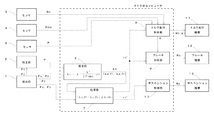
図1は、本実施形態にかかる車両制御装置の全体構成を示したブロック構成図である。この車両制御装置は、左右の車輪のコーナリングパワーkaを考慮して、左右の車輪に対する前後力配分比、または、左右の車輪に対する上下力配分比を決定する。そして、車輪に作用する前後力が、この決定された前後力配分比となるように、左右の車輪に対する駆動力配分比(或いは制動力配分比)が制御される。または、車輪に作用する上下力が、この決定された上下力配分比となるように、左右輪に対する垂直荷重配分比が制御される。これにより、車両の状態(すなわち、車輪の状態量)が変化するため、左右の車輪のコーナリングパワーkaが所望とする値に近づく方向に作用し、車両の操安性の向上を図ることができる。まず、本実施形態にかかる車両制御の概念を明確にすべく、コーナリングパワーkaについて説明し、その後に車両制御装置の具体的なシステム構成およびシステム処理について説明する。
【0019】
コーナリングパワーkaは、車輪すべり角βwの微小変化による横力Fy(車輪があるすべり角βwで旋回するときに、接地面に発生する摩擦力のうち車輪中心面に直角な方向に発生する分力)の変化率である。すなわち、コーナリングパワーkaは、ある車輪すべり角βwにおける横力Fyの傾き(微分値)として定義することができる。そのため、コーナリングパワーkaは、車輪すべり角βwと横力Fyとの関係に基づいて、一義的に導出することができる。このコーナリングパワーkaは車両の操安性に大きな影響を与えるパラメータであり、この値が大きいと操舵に対する車両の挙動変化の応答性が速くなり、この値が小さいと操舵に対する車両の挙動変化の応答性が緩慢になる。例えば、コーナリング走行時、或いは、低摩擦係数路面での走行時において、挙動変化の応答性は速いことが望ましく、基本的に、コーナリングパワーkaは大きい方が好ましい。
【0020】
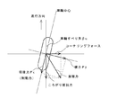
図2は、車輪に作用する作用力を示した説明図である。同図に示すように、車輪に関する作用力としては、上述した横力Fyの他に、前後力Fx、コーナリングフォースなどが挙げられる。車輪があるすべり角βwで旋回するときに、接地面に発生する摩擦力のうち車輪中心面に平行な方向に発生する分力が前後力Fxであり、車輪進行方向に直角な方向に発生する分力がコーナリングフォースである。また、図中には明記しないが、車輪に関する作用力としては、さらに垂直方向の荷重、所謂上下力Fz(図示せず)が挙げられる。
【0021】
作用力として挙げられるこれらの力のうち、横力Fyとコーナリングフォースとは比較的に類似した力として扱うことができる。横力Fyとコーナリングフォースとは値として一対一に対応するものではないが、実用上、車両がとり得る車輪すべり角βwの範囲内において両者の値は近似する。本明細書では、コーナリングフォースと横力Fyとを実質的に同じと見なし、横力Fyをベースとしてコーナリングパワーkaについて考える。すなわち、横力Fyとコーナリングパワーkaとの関係が事前に分かっていれば、コーナリングパワーkaは、横力Fyに基づいて、一義的に特定されることになる。以下、横力Fyとコーナリングパワーkaとの関係について考える。
【0022】
車輪すべり角βwと、車輪に作用する横力Fyとは、以下に示す数式1を満たす。
【数1】

この数式1は、車輪の力学特性を示すタイヤモデルに基づき、車輪に作用する横力Fyを車輪すべり角βwで二次近似した式である。同数式において、係数kは、実験的に求めることができる定数であり、車輪と路面との間の摩擦係数μおよび上下力Fzに依存して変化する(数式2)。
【数2】
この係数kは車輪の特性を示す値であり、この値が高いと車輪の剛性が高いことを意味し、また、値が小さいと車輪の剛性が低いことを意味する。同数式から分かるように、係数kは、車輪すべり角βwが0における横力Fyの傾き(微分値)である。以下、この値を基準コーナリングパワーkと称する。
【0025】
一方、横力Fyの取り得る最大値である横力最大値Fymaxは、上下力Fz、前後力Fxおよび摩擦係数μから、数式3に基づき算出される。
【数3】
また、コーナリングパワーkaは、ある車輪すべり角βwにおける横力Fyの傾き(微分値)であるので、コーナリングパワーkaは、数式1を車輪すべり角βwで微分した数式4として表すことができる。
【数4】
数式1〜4から分かるように、車輪に作用する前後力Fx、横力Fyおよび上下力Fzと、摩擦係数μとが既知となれば、車輪すべり角βwは、一意に特定される。この車輪すべり角βwが特定されると、車輪のコーナリングパワーkaは、車輪すべり角βwと横力Fyとの関係に基づいて、一義的に算出することができる。
【0028】
つぎに、前後力Fx(または上下力Fz)とコーナリングパワーkaとの関係について説明する。前後力Fxとコーナリングパワーkaとの関係は、数式1および数式4から車輪すべり角βwを消去することにより、数式5として表すことができる。
【数5】
ここで、同数式中のFymaxを数式3で置換すると、数式5は数式6となる。
【数6】
このコーナリングパワーkaの傾向を見るため、数式6の分数部分を摩擦係数μと上下力Fzとの積(μ・Fz)で割り、無次元化する(数式7)。
【数7】
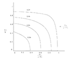
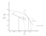
図3は、前後力Fxとコーナリングパワーkaとの関係を示した図である。同図は数式7をグラフ化したものであり、縦軸はコーナリングパワーkaを表し、横軸は無次元化した前後力(Fx/μFz)を表している。なお、説明の便宜上、コーナリングパワーkaを基準コーナリングパワーkで割ることにより、縦軸も無次元化されている。同図では、横軸上を0から1へ向かう程、前後力Fxが大きくなることを意味し、縦軸上を0から1へ向かう程、コーナリングパワーkaが大きくなることを意味する。また、同図には、数式7における分子部分(Fy/μFz)の値を0.2,0.4,0.6,0.8とした場合の、前後力Fxとコーナリングパワーkaとの関係がそれぞれ実線で示されている。各実線はこの分子部分(Fy/μFz)の値に拘わらず基本的に同じ傾向を示すものの、この値(Fy/μFz)が大きくなるに従い、前後力Fxとコーナリングパワーkaとの関係は相対的に小さくなっている。同図から分かるように、コーナリングパワーkaは、前後力Fxが小さくなる程その値が大きくなり、前後力Fxが大きくなる程その値が小さくなる。したがって、車輪のコーナリングパワーkaを大きくするためには、車輪に作用する前後力Fxを小さくすればよいことになる。前後力Fxの調整は、車輪に加えられる駆動力または制動力を制御することにより行うことができる。
【0032】
4つの車輪を備えた一般的な車両において、車輪に駆動力(または制動力)が定常的に加えられている状態を想定する。各車輪に作用する前後力Fxの総和は一定であるため、ある車輪に作用する前後力Fxを小さくすると、これに応じて他の車輪に作用する前後力Fxが大きくなる。そのため、各車輪に作用する前後力Fxのすべてを小さくするは困難であり、それ故に、各車輪のコーナリングパワーkaのすべてを大きくすることもまた困難である。そこで、本実施形態では、左右輪に対する前後力配分比rxを変化させることで、左右輪の各コーナリングパワーkaの代表値(例えば、平均値)が、現在の値よりも大きくなるような(好ましくは、最大値となるような)制御を行うことにする(左右輪のコーナリングパワーkaの最大化)。
【0033】
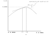
図4は、正規化された左右輪のコーナリングパワーの平均値ka_aveと左右輪の前後力配分比rxとの関係を示す図である。同図には、一例として、左旋回時の内輪(左前輪)と外輪(右前輪)とに関するこれらの関係が示されている。以下、左前輪のコーナリングパワーkaをコーナリングパワーka_fl、右前輪のコーナリングパワーkaをコーナリングパワーka_frと記述し、各車輪のコーナリングパワーkaを区別する。同図に示す関係は、数式7に基づき算出される各コーナリングパワーka_fl,ka_frから、左右輪のコーナリングパワーの平均値ka_ave((ka_fl+ka_fr)/2)と、前後力配分比rxとの関係を導き出すことにより、一義的に求めることができる。左右輪のコーナリングパワーの平均値ka_aveを縦軸、前後力配分比rxを横軸に設定した場合、両者の関係は、ある前後力配分比rx(rx0)において極大値(ka_avemax)を有する、上に凸のグラフとなる。なお、車両が左旋回をしている場合、極大値となり得る前後力配分比rx0は、前後力配分比rxが左右輪に対して一対一となる位置よりも外(右)輪偏重寄りに存在する。
【0034】
同図を参照し、左右輪に対する前後力配分比rxによるコーナリングパワーの平均値ka_aveの変化率Δkについて考える。この変化率Δkは、ある前後力配分比rxにおけるコーナリングパワーの平均値ka_aveの接線(直線L1)に関する傾き(微分値)である。具体的には、この直線L1は、前後力配分比rxが最も内輪偏重(左輪偏重)の場合に最も右上がりの直線(Δk:正の値)となり、前後力配分比rxが外輪偏重(右輪偏重)になるに従い、その傾きが水平に近づいていく。前後力配分比rx0において、直線L1は、水平な直線(Δk:0)となり、前後力配分比rxがさらに外輪偏重(右輪偏重)になるに従い、右下がりの直線となっていく。そして、前後力配分比rxが最も外輪偏重(右輪偏重)の場合に、直線L1は、最も右下がりの直線(Δk:負の値)となる。
【0035】
ここで、現在の前後力配分比rxを、例えば、左右輪に対して一対一の状態(前後力配分比rx1)と考える。図4に示すように、車両が左旋回をしている場合、この配分比rx1は前後力配分比rx0よりも内(左)輪偏重寄りに位置するため、直線L1は右上がりの傾向を示し、変化率Δkは正の所定値となる。この前後力配分比rxにおいて、左右輪のコーナリングパワーの平均値ka_aveを大きくするためには、直線L1の傾きがなだらかになる方向に(Δkが減少する方向に)、前後力配分比rxを変化させる必要がある。同図に示す例では、前後力配分比rxを現在の前後力配分比rx1よりも外輪偏重にすれば、直線L1の傾きがなだらかになり(Δkが減少し)、コーナリングパワーの平均値ka_aveは極大値ka_avemaxに向かって大きくなる。したがって、どのような走行状況であっても、変化率Δkを0に近づける方向に前後力配分比rxを変化させれば、コーナリングパワーの平均値ka_aveは、極大値ka_avemaxに向かって大きくなることになる(好ましくは、極大値ka_avemaxと一致する)。
【0036】
上記の変化率Δkは、以下に示す数式8として表すことができる。
【数8】
数式8において、k_flは左前輪の基準コーナリングパワーkであり、k_frは右前輪の基準コーナリングパワーkである。一方、kc_flは、左前輪に関する無次元化した前後力Fx/μFzによる無次元化したコーナリングパワーka_fl/k_flの変化率(以下、単に「左前輪変化率kc_fl」という)である。また、kc_frは、右前輪に関する無次元化した前後力Fx/μFzによる無次元化したコーナリングパワーka_fr/k_frの変化率(以下、単に「右前輪変化率kc_fr」という)である。数式8から分かるように、変化率Δkは、右前輪変化率kc_frと右前輪の基準コーナリングパワーk_frとの積(kc_fr・k_fr)と、左前輪変化率kc_flと左前輪の基準コーナリングパワーk_flとの積(kc_fl・k_fl)との差に比例する。したがって、この変化率Δkを0に近づけるためには、これらの積kc_fr・k_fr,kc_fl・k_flの値が近づけばよいことになる。
【0038】
図5はコーナリングパワーkaと前後力Fxとの関係を示した図であり、図3と同様、横軸(前後力Fx)および縦軸(コーナリングパワーka)は無次元化されている。図4と同様に、前後力配分比rxが左右輪に対して一対一の状況で車両が左旋回をしていると考える。同図には、内輪(左前輪)のコーナリングパワーka_flと前後力Fxとの関係が実線で示されており、外輪(右前輪)のコーナリングパワーka_frと前後力Fxとの関係が点線で示されている。同図において、上述の左前輪変化率kc_flは、ある前後力Fxにおける左前輪のコーナリングパワーka_flの接線(直線L2)に関する傾き(微分値)に相当する。また、右前輪変化率kc_frは、ある前後力Fxにおける右前輪のコーナリングパワーka_frの接線(直線L3)に関する傾き(微分値)に相当する。図5において、縦軸は無次元化されているが、正規化されたコーナリングパワーka_fl(またはka_fr)を縦軸とした場合、各直線L2,L3の傾きはそれぞれkc_fl・k_fl(直線L2)、kc_fr・k_fr(直線L3)となる。したがって、上記数式8に示す変化率Δkを0に近づけることは、直線L2の傾き(左前輪変化率kc_fl)と直線L3の傾き(右前輪変化率kc_fr)とを近づけることと等価である。
【0039】
そこで、前後力Fxの変化に応じた各変化率kc_fl,kc_frの傾向について考えてみる。左右前輪のコーナリングパワーka_fl,ka_frと前後力Fxとの関係は、値の大小はあるものの基本的に同じグラフ傾向を示すため、前後力Fxの変化に応じた各変化率kc_fl,kc_frの傾向も同じと考えることができる。そのため、ここでは、前後力Fxの変化に応じた左前輪変化率kc_flの傾向についてのみ考える。左前輪に作用する前後力Fxが最大の場合、直線L2は傾きが急な右下がりの直線となり、左前輪変化率kc_flは最小値(負の値)をとなる。この状態から左前輪に作用する前後力Fxが小さくなっていくと、直線L2は傾きなだらかな直線へと変わっていき、左前輪変化率kc_flは大きくなる。そして、左前輪に作用する前後力Fxが0の場合、直線L2は傾きが最もなだらになり、左前輪変化率kc_flは最大値(負の値)となる。
【0040】
例えば、図5に示すように、左前輪変化率kc_flが右前輪変化率kc_frよりも小さい場合(kc_fr>kc_fl)、すなわち、直線L2が直線L3よりも傾きが急な場合について考える。これらの直線L2,L3の傾きを近づけるためには、左前輪の前後力Fxを小さくすることで、直線L2の傾きを現在の傾きよりもなだらかな方向へ変えるとともに、右前輪の前後力Fxを大きくすることで、直線L3の傾きを現在の傾きよりも急な方向へ変えればよい。換言すれば、左前輪変化率kc_flと、右前輪変化率kc_frとを比較して、変化率が小さい一方の車輪(図5に示す例では左前輪)に作用する前後力Fxを小さくし、変化率が大きい他方の車輪(図5に示す例では右前輪)に作用する前後力Fxを大きくすればよい。これにより、直線L2の傾き(左前輪変化率kc_fl)と直線L3の傾き(右前輪変化率kc_fr)とが近づく方向に作用し、上記Δkが0に近づく方向に作用する。そのため、本実施形態では、このような知得に基づき、現在の前後力配分比rxから所定量分だけ配分比を変化させることにより、Δkが0に近づくような目標前後力配分比rx’を決定する。そして、車輪に作用する前後力が目標前後力配分比rx’となるように、駆動力(制動力)配分比Rxを制御する。例えば、図5に示す例では、現在の前後力配分比rxよりも右輪偏重となるように、目標前後力配分比rx’を決定するといった如くである。
【0041】
再び図3を参照すると、無次元化されたグラフからは、上下力Fzとコーナリングパワーkaとの関係も把握することができる。同図において、横軸上を0から1へ向かう程、上下力Fzが小さくなることを意味する。コーナリングパワーkaは、上下力Fzが小さくなる程その値が小さくなり、上下力Fzが大きくなる程その値が大きくなる。すなわち、車輪のコーナリングパワーkaを大きくするためには、車輪に作用する上下力Fzを大きくすればよいことになる。上下力Fzの調整は、車輪にかかる垂直荷重を制御することにより行うことができる。ただし、上述した前後力Fxと同様、各車輪に作用する上下力Fzの総和は一定である。そこで、左右輪に対する上下力配分比rzを調整することにより、コーナリングパワーkaの最大化を図ることにする。
【0042】
図3に示す関係は無次元化したものであるため、正規化された左右輪のコーナリングパワーの平均値ka_aveと左右輪に対する上下力配分比rzとの関係も、図4と同様の傾向を示す。すなわち、左右輪のコーナリングパワーの平均値ka_aveを縦軸、上下力配分比rzを横軸に設定した場合、両者の関係は、ある上下力配分比rz(rz0(rx0に相当))において極大値(ka_avemax)を有する、上に凸のグラフとなる。したがって、変化率Δkを0に近づける方向に上下力配分比rzを変化させれば、コーナリングパワーの平均値ka_aveは、極大値ka_avemaxに向かって大きくなる。この変化率Δkを0に近づけるためには、数式8に示した各積kc_fr・k_fr,kc_fl・k_flが値として近づけばよいことになる。
【0043】
図5は、無次元化されているため、上下力Fzとコーナリングパワーkaとの関係も理解することができる。例えば、同図に示すように、現在の左前輪変化率kc_flが右前輪変化率kc_frよりも小さい場合(kc_fr>kc_fl)、すなわち、直線L2が直線L3よりも傾きが急な場合について考える。これらの直線L2,L3の傾きを近づけるためには、左前輪の上下力Fzを大きくすることで、直線L2の傾きを現在の傾きよりもなだらかな方向へ変えるとともに、右前輪の上下力Fzを小さくするで、直線L3の傾きを現在の傾きよりも急な方向へ変えればよい。換言すれば、左前輪変化率kc_flと、右前輪変化率kc_frとを比較して、変化率が小さい一方の車輪(図5に示す例では左車輪)に作用する上下力Fzを大きくし、変化率が大きい他方の車輪(図5に示す例では右車輪)に作用する上下力Fzを小さくすればよい。これにより、直線L2の傾き(左前輪変化率kc_fl)と直線L3の傾き(右前輪変化率kc_fr)とが近づく方向に作用し、上記Δkが0に近づく方向に作用する。そこで、本実施形態では、現在の上下力配分比rzから所定量分だけ配分比を変化させることにより、Δkが0に近づくような目標上下力配分比rz’を決定する。そして、車輪に作用する上下力が目標上下力配分比rz’となるように、垂直荷重配分比Rzを制御することとする。例えば、図5に示す例では、現在の上下力配分比rzよりも左輪偏重となるように、目標上下力配分比rz’を決定するといった如くである。
【0044】
以上のような車両制御の概念を踏まえた上で、再び図1を参照して、本実施形態にかかる車両制御装置のシステム構成について説明する。車両制御装置としては、CPU、RAM、ROM、入出力インターフェースなどで構成されたマイクロコンピュータを用いることができる。車両制御装置は、ROMに記憶された制御プログラムに従い、上述した制御値(例えば、前後力配分比rx、上下力配分比rz)に関する演算を行う。そして、この演算によって算出された制御値に応じた駆動力(制動力)配分比または垂直荷重配分比が演算され、この演算結果に応じた制御信号が各種アクチュエータに対して出力される。車両制御装置には、このような演算を行うために、検出部1から得られる車輪に作用する作用力、特定部2から得られる車輪と路面との間の摩擦係数μが入力されている。また、この車両制御装置には、センサ3,4から得られた車両状態信号(エンジン回転数Ne、アクセル開度θacc)およびセンサ5から得られた現在のトランスミッションのギヤ位置を示すギヤ位置信号Pがさらに入力されている。
【0045】
検出部1は、車輪に接続する車軸に取付けられた少なくとも一つ以上の応力検出センサ(例えば、抵抗歪ゲージ)と、この応力検出センサからの検出信号を処理する信号処理回路とで構成される。この検出部1は各車輪に設けられており、各車輪に関する作用力が車両制御装置に対して入力される。作用力に起因して車軸に生じる応力はこの作用力に比例するという知得に基づき、検出部1は、応力を通じて作用力を検出する。検出部1によって検出される作用力は、横力Fy、前後力Fxおよび上下力Fzの3つである。なお、図1において、検出部1は便宜上一つのブロックとして明記されているが、このブロックは各車輪に設けられる検出部1のすべてを総括している。検出部1に関する詳細な構成については、特開平4−331336号公報に記載されているので、必要ならば参照されたい。
【0046】
特定部2は、車輪と路面との間の摩擦係数μを特定する。本実施形態において、特定部2は、上述した検出部1からの出力情報を用いることにより、路面摩擦力(すなわち、前後力Fx)と上下力Fzとの比として摩擦係数μを特定する。ただし、摩擦係数μを特定する場合、特定部2は、検出部1からの出力値に基づいてこれを特定する以外に、周知の手法を用いて推定してもよい。摩擦係数μを推定する手法としては、例えば、現在の車両のヨーレート、舵角、横加速度および車速を、種々の摩擦係数μにおけるこれらの値と比較することにより、推定する手法が挙げられる。このような推定手法の一例は、本出願人によって既に提案されている特開平8−2274号公報に開示されているので、必要ならば参照されたい。なお、検出部1が自身の検出結果に基づいて摩擦係数μを算出するのであれば、図1に示す特定部2を省略し、検出部1が特定部2としての機能を果たしてもよい。
【0047】
マイクロコンピュータを機能的に捉えた場合、この車両制御装置は、推定部6と、処理部7と、制御部8〜10とで構成される。推定部6は、各車輪について検出された作用力Fx,Fy,Fzと、特定された摩擦係数μとを読み込む。そして、この読み込まれた値に基づいて、各車輪のコーナリングパワーkaを算出する。処理部7は、各車輪のコーナリングパワーkaに基づいて算出される、左右の車輪のコーナリングパワーの平均値ka_aveが、左右輪の車輪のコーナリングパワーの平均値ka_aveの現在値よりも大きくなるように、前後力配分比rx(または上下力配分比rz)を決定する。具体的には、処理部7は、左右の車輪毎に、前後力Fx(または上下力Fz)によるコーナリングパワーkaの変化率kc_fl,kc_frを算出する。そして、算出された左右の車輪に関する変化率kc_fl,kc_frに基づき、左車輪に関する変化率kc_flと、右車輪に関する変化率kc_frとが近づくように、前後力配分比rx(または上下力配分比rz)が決定される。この決定された前後力配分比rx(または上下力配分比rz)は、制御信号として制御部8〜10のいずれかに対して出力される。
【0048】
この制御部8〜10はトルク配分制御部8、ブレーキ制御部9およびサスペンション制御部10で構成されており、各制御部8〜10は制御対象となる車両の状態に応じて適宜使い分けられる。例えば、処理部7が演算を行うことにより、所定の前後力配分比rxを決定した場合、処理部7はこの値に応じた制御信号をトルク配分制御部8またはブレーキ制御部9に対して出力する。これにより、トルク配分制御部8がトルク配分機構11を制御する、或いは、ブレーキ制御部9がブレーキ機構12を制御することにより、左右輪に対する駆動力配分比(または制動力配分比)Rxが制御される。また、処理部7が演算を行うことにより、所定の上下力配分比rzを決定した場合、処理部7はこの値に応じた制御信号をサスペンション制御部10に対して出力する。これにより、サスペンション制御部10がサスペンション機構13を制御することにより、左右輪に対する垂直荷重配分比Rzが制御される。
【0049】
図6は、本実施形態にかかる車両制御の手順を示したフローチャートである。このフローチャートに示した処理は、所定間隔毎に呼び出され、マイクロコンピュータによって実行される。以下、同図を参照し、本実施形態にかかるシステム処理を説明するが、ここでは、前輪における左右輪の前後力配分比rxを制御することにより、前輪に関する左右輪のコーナリングパワーkaを最大化する手法について説明する。まず、ステップ1において、推定部6は摩擦係数μを読み込む。そして、推定部6は、検出部1からのセンサ信号から、前後力Fx、横力Fyおよび上下力Fzを読み込む(ステップ2)。つぎに、読み込まれた情報を用い、上記の数式4に基づいて、各車輪のコーナリングパワーkaが算出される(ステップ3)。
【0050】
ステップ4において、算出された各車輪のコーナリングパワーkaに基づいて、左前輪に関する前後力Fxによるコーナリングパワーka_flの変化率(左前輪変化率)kc_flが算出される。具体的には、左前輪変化率kc_flは、算出された左前輪のコーナリングパワーka_flに基づいて、この値ka_flに対応した接線(例えば、図5に示した直線L2)に関する傾き(微分値)として算出される。また、右前輪に関する前後力Fxによるコーナリングパワーka_frの変化率(右前輪変化率)kc_frが同様の手法により算出される。
【0051】
ステップ5において、左前輪変化率kc_flと右前輪変化率kc_frとの差の絶対値が、所定の判定値kcthよりも大きいか否かが判定される。このような判定処理を設ける理由は、各変化率kc_fl,kc_frが現段階で近似している場合には、すでに左右輪のコーナリングパワーの平均値ka_aveが最大付近となっている可能性が高く、あえて車両の状態を変える必要がないからである。そのため、このような状況での制御を回避すべく、ステップ6、7の処理に先立ち、コーナリングパワーkaを最大化する必要があるか否かの判定が行われる。
【0052】
上記の判定値kcthは、左前輪変化率kc_flと右前輪変化率kc_frとが実質的に同一と見なせる程度の、各変化率kc_fl,kc_frの差の絶対値に関する最大値として、実験やシミュレーションを通じて予め設定されている。したがって、この判定により肯定された場合(すなわち、左前輪変化率kc_flと右前輪変化率kc_frとの差の絶対値が判定値kcthよりも大きい場合)には、このステップ5に続くステップ6に進む。一方、この判定により否定された場合(左前輪変化率kc_flと右前輪変化率kc_frとの差分の絶対値が判定値kcth以下である場合)、ステップ6、7をスキップして本ルーチンを抜ける。
【0053】
ステップ5に続くステップ6において、現在の左右前輪における前後力配分比rxに基づいて、目標前後力配分比rx’が決定される。具体的には、まず、算出された左右前輪の各変化率kc_fl,kc_frが比較される。そして、現在の前後力配分比rxよりも、変化率が小さい一方の車輪に作用する前後力Fxを小さく、変化率が大きい他方の車輪に作用する前後力Fxを大きくするような値として、目標前後力配分比rx’が求められる。例えば、図5に示したように、左前輪変化率kc_flよりも右前輪変化率kc_frの方が大きい状況では、現在の前後力配分比rxよりもステップ値相当だけ右前輪偏重となるように、目標前後力配分比rx’が算出される。一方、左前輪変化率kc_flよりも右前輪変化率kc_frが小さい状況では、現在の前後力配分比rxよりもステップ値相当だけ左前輪偏重となるように、目標前後力配分比rx’が算出される。
【0054】
ステップ7において、決定された目標前後力配分比rx’に基づいて、左右前輪に対する駆動力配分比Rxが算出される。具体的には、まず、エンジン回転数Neおよびスロットル開度θaccに基づいて、エンジン出力が推定される。つぎに、ギヤ位置Pに相当するギヤ比と乗算することにより、入力トルクTiが算出される。そして、目標前後力配分比rx’と、入力トルクTiとに基づき、前後輪に対するトルク配分比を考慮した上で、目標前後力配分比rx’となるような左右前輪に対するトルク配分比α(すなわち、駆動力配分比Rx)が算出される。そして、トルク配分制御部8は、決定された左右輪に対するトルク配分比αに応じた制御信号をトルク配分機構11に対して出力し、本ルーチンを抜ける。
【0055】
トルク配分機構(例えば、フロントデファレンシャル装置)11は、出力された制御信号に応じて作動し、左右前輪に加えられるトルク配分を制御する。これにより、左右前輪に作用する前後力Fxがステップ値相当だけ調整された目標前後力配分比rx’となるように、駆動力配分比Rxが制御される。なお、車輪にかかる駆動力配分制御に関する詳細については、特開平8−2274号公報に開示されているので、必要ならば参照されたい。
【0056】
このように、本実施形態によれば、左前輪に関する前後力Fxによるコーナリングパワーの変化率(左前輪変化率)kc_flと、右前輪に関する前後力Fxによるコーナリングパワーの変化率(右前輪変化率)kc_frとが算出される。つぎに、算出された各変化率kc_fl,kc_frを比較することにより、変化率が小さい一方の車輪に作用する前後力Fxを小さく、変化率が大きい他方の車輪に作用する前後力Fxを大きくするように、目標前後力配分比rx’が決定される。そして、車輪に作用する前後力Fxがこの目標前後力配分比rx’となるように、駆動力配分比Rxが制御される。これにより、車両の状態が変化し、左前輪変化率kc_flと、右前輪変化率kc_frとが近づく方向に作用することになり、左右前輪のコーナリングパワーの平均値ka_aveは、車両の状態を制御する前のそれよりも大きくなる。上述の如く、個々の車輪のコーナリングパワーkaを個別で大きくすることは困難であるが、このような制御を行うことにより、前輪(または後輪)の全体でコーナリングパワーkaを平均的に大きくすることができる。よって、挙動変化の応答性を速くすることができるので、例えば、コーナリングといった走行状況における車両の操安性の向上を図ることができる。
【0057】
上述の実施形態では、前輪の左右輪を制御対象としてコーナリングパワーの平均値ka_aveの最大化を説明したが、同様の概念に基づいて、後輪の左右輪の左右輪を制御対象としてコーナリングパワーkaの最大化を図ることもできる。また、前後輪のそれぞれの左右輪を制御対象として、コーナリングパワーkaの最大化を図ってもよい。
【0058】
また、制御の安定性を優先させる上で、ステップ値(微小値)相当の制御を行ったが、左前輪変化率kc_flと、右前輪変化率kc_frとが同じとなるような、目標前後力配分比rx’を直接的に求めてもよい。この目標前後力配分比rx’は、左前輪変化率kc_flと右前輪変化率kc_frとを等価と見なし、所定の数値演算を行うことにより一義的に求めることができる。ただし、かかる手法は、演算が複雑であり、処理の煩雑化につながるので、左前輪変化率kc_flと右前輪変化率kc_frとが同じとなるような目標前後力配分比rx’を、収束演算などに基づいて求めてもよい。
【0059】
なお、本明細書では、左右輪のコーナリングパワーkaの代表値として平均値を用いて説明したが、平均値以外にも、左右輪のコーナリングパワーkaの総和または積などを用いてもよい。左右輪のコーナリングパワーkaの総和または積を用いても基本的な概念は同じであり、左右輪のコーナリングパワーkaの代表値が現在値よりも大きくなるように車両の状態を制御することにより、操安性の向上を図ることができる。
【0060】
また、目標前後力配分比rx’となるように、車両の状態を制御をするのであれば、制動力配分比Rxを制御することにより、これを行うこともできる。かかる制御は、ブレーキ制御部9によって行われる。このブレーキ制御部9には、上述したトルク配分制御部8からの情報(すなわち、トルク配分比α)が入力されている。そのため、ブレーキ制御部9は、このトルク配分比αと、目標前後力配分比rx’とに基づいて、車輪に作用する前後力Fxが目標前後力配分比rx’となるように、制動力配分比Rxを算出する。そして、決定された制動力配分比Rxに応じた制御信号をブレーキ機構12に対して出力する。これにより、ブレーキ機構(例えば、ABS装置)12が、ブレーキ制御部9から出力された制御信号に応じて作動し、車輪に加えられる制動力配分が制御される。具体的には、車輪に作用する前後力Fxがステップ値相当だけ調整された目標前後力配分比rx’となるように、制動力配分比Rxが制御される。これにより、左前輪変化率kc_flと、右前輪変化率kc_frとが近づく方向に作用することで、左右輪のコーナリングパワーの平均値ka_aveを現在のそれよりも大きくすることができる。
【0061】
また、上述した説明では、左右輪に対する前後力配分比rxを調整することにより、左右輪のコーナリングパワーの最大化を説明した。しかしながら、上述した概念に基づき、左右輪に対する上下力配分比rzを調整することにより、左右輪のコーナリングパワーの最大化を図ってもよい。なお、システム処理の内容は、基本的に、図6に示す処理と同じであり、ここでの説明は省略する。特に相違する点は、処理部7が、ステップ値相当だけ変位させた目標上下力配分比rz’を決定することである。具体的には、左右の車輪に関する各変化率kc_fl,kc_frのうち、変化率が小さい一方の車輪に作用する上下力Fzを大きく、変化率が大きい他方の車輪に作用する上下力Fzを小さくするように、目標上下力配分比rz’が決定される。そして、決定された目標上下力配分比rz’に応じた制御信号が、サスペンション制御部10に対して出力される。サスペンション制御部10は、車輪に作用する上下力Fzが目標上下力配分比rz’となるように、左右輪に対する垂直荷重配分比Rzを決定し、決定した値に応じた制御信号をサスペンション機構13に対して出力する。これにより、サスペンション機構13が、サスペンション制御部10から出力された制御信号に応じて作動し、車輪に加えられる垂直荷重配分zが制御される。具体的には、車輪に作用する上下力Fzがステップ値相当だけ調整された目標上下力配分比rz’となるように、垂直荷重配分比Rzが制御される。これにより、左前輪変化率kc_flと、右前輪変化率kc_frとが近づく方向に作用することで、左右輪のコーナリングパワーの平均値ka_aveを現在のそれよりも大きくすることができる。なお、車輪に作用する垂直荷重制御手法の詳細については、特開昭62−275814号公報に開示されているので、必要ならば参照されたい。
【0062】
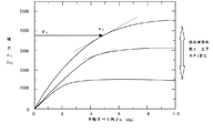
本実施形態では、車輪すべり角βwと横力Fyとの関係をタイヤモデルを用い、これを二次近似することで定義したが、本発明はこれに限定されるものではない。例えば、車輪すべり角βwと横力Fyとの関係は、様々な条件下(前後力Fx、上下力Fzおよび摩擦係数μ)で実験的に求められるタイヤ特性を用いたり、別の数値モデル(Fialaモデル等)を用いたりして定義することもできる。図7は、実験的に算出された車輪すべり角βwと横力Fyとの関係の一例を示す説明図である。このような実験値を用いたとしても、車輪すべり角βwと横力Fyとの関係に基づき、車輪のコーナリングパワーkaは、車輪すべり角βwの増加とともに増す横力Fyの割合(すなわち、微分値)として、一義的に算出される。
【0063】
また、上述した実施形態では、コーナリングパワーkaを、数式4として定義したが、数式9として簡略的に算出することができる。
【数9】
ここで、上述したコーナリングパワーkaと区別するため、同数式に示すkpを偽コーナリングパワーと称する。この偽コーナリングパワーkpは、基本的に、数式4に示すコーナリングパワーkaとほぼ同様な傾向を示す。したがって、上述した実施形態で用いたコーナリングパワーkaに変えて、この偽コーナリングパワーkpを用いても、同様の作用と効果とを奏することができる。
【0065】
また、上述した検出部1は、車輪に作用する作用力を直接検出しているため、非線形性の要素が強いコーナリングパワーkaを精度よく特定することができる。その結果、例えば、限界コーナリングといった走行状況であったとしても、或いは、低摩擦係数路面といった走行状況であったとしても、コーナリングパワーkaを精度よく特定することができる。これにより、より有効に、コーナリングパワーの最大化を図ることができる。
【0066】
(第2の実施形態)
第2の実施形態では、上述した左右輪のコーナリングパワーkaの最大化を行うとともに、車両のスタビリティファクタを目標スタビリティファクタに近づけるように、制御値をさらに決定する。ここで、スタビリティファクタとは、車両のステア特性を示す評価値であり、コーナリング時の車両の挙動(すなわち、安定性)の目安となる値である。この値が正の場合、車両はアンダーステア傾向となり、この値が負の場合、車両はオーバーステア傾向となる。このスタビリティファクタの最適値は車両によって異なり、設計段階などにおいて設定される。このスタビリティファクタの最適値を常に追従するように車両が走行することで、車両の運動状態は適切に維持される。以下、左右輪のコーナリングパワーkaの最大化と、スタビリティファクタとの関係について説明する。
【0067】
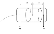
図8は、車両に作用するモーメントを示す説明図である。操舵角一定で走行している車両を考えた場合、前輪に働く力Ffによって生じる車体周りのモーメントM1(Ff×lf,lf:車両の重心から前輪までの距離)と、後輪に働く力Frによって生じる車体周りのモーメントM2(Fr×lr,lr:車両の重心から後輪までの距離)は、通常釣り合っている。この関係から、ステア特性を数式によって求める場合に使われる係数がスタビリティファクタである。しかしながら、第1の実施形態に示すように、前輪(或いは後輪)における左右輪の前後力配分比rxを変えると、車両には、この前後力配分比制御に応じたヨーモーメントが発生する。これにより、初期的には釣り合っていたモーメントM1,M2の釣り合いがくずれ、スタビリティファクタが最適値から外れてしまう虞がある。そこで、第2の実施形態では、左右輪に対する前後力配分比制御を加味した上で、現在の車両のスタビリティファクタが目標スタビリティファクタに近づくように車両の状態をさらに制御することにある。ここで、スタビリティファクタの基本形を数式10に示す。
【数10】
ここで、mは車両の質量、lfは前輪の車軸軸と車両の重心との間の距離、lrは後輪の車軸と車両の重心との間の距離である。また、ka_faveは、左前輪のコーナリングパワーをka_fl、右前輪のコーナリングパワーをka_frとした場合の、両コーナリングパワーka_fl,ka_frの平均値である。同様に、ka_raveは、左後輪のコーナリングパワーをka_rl、右後輪のコーナリングパワーをka_rrとした場合の、両コーナリングパワーka_rl,ka_rrの平均値である。
【0069】
センサなどから求められるスタビリティファクタを実スタビリティファクタA1とすれば、左右輪の前後力配分比制御によるヨーモーメントを考慮した実スタビリティファクタA1は、下式で表すことができる。
【数11】
ここで、ΔFxは左右輪の前後力差(外輪の駆動力が大きい方向を正とする)であり、dはトレッド、y”は横加速度である。また、検出部1または特定部2などにより求められる値には、記号の後ろに「1」が添えられている。
【0071】
また、スタビリティファクタAの最適値を目標スタビリティファクタA2とすると、実スタビリティファクタA1が目標スタビリティファクタA2に近づくようにするには、以下に示す数式12が「0」に近づけばよい。
【数12】
ここで、目標スタビリティファクタA2に関する各値ka_fave,ka_raveには、記号の後ろに「2」が添えられている。これらの値ka_fave2,ka_rave2は、目標スタビリティファクタA2に応じて予め設定されている値である。数式12に示すΔAが0に近づくためには、数式13に示す等式が成り立つように、前輪のコーナリングパワーの平均値ka_fave1と、後輪のコーナリングパワーの平均値ka_rave1とを制御すればよい。
【数13】
左右輪の前後力配分比rxを制御する以前に車両が目標スタビリティファクタA2を満たしていたと考えた場合、この前後力配分比制御により、仮想的に車両の重心位置が所定値(ΔFx・d/m・y”)だけ後方に移動したと考えることができる。数式13を成立させるためには、前輪のコーナリングパワーの平均値ka_fave1を大きくし、後輪のコーナリングパワーの平均値ka_rave1を小さくすればよい。このようなコーナリングパワーを実現するためには、現在の前後輪に対する前後力配分比よりもステップ値相当だけ後輪偏重となるように、前後輪の前後力配分比を決定すればよいことになる。そして、前後輪に作用する前後力が、この決定された前後力配分比となるように、前後輪に対する駆動力配分比(或いは制動力配分比)を制御すればよい。あるいは、現在の上下力配分比よりもステップ値相当だけ前輪偏重となるように、前後輪の上下力配分比を決定してもよい。このケースでは、前後輪に作用する上下力が、この決定された前後力配分比となるように、前後輪に対する垂直荷重配分比を制御すればよい。
【0074】
このように、ステップ値相当だけ、前後輪に対する前後力配分比または上下力配分比を制御することより、実スタビリティファクタA1が目標スタビリティに近づく方向に作用する。これにより、左右輪に対する前後力配分比制御に起因したヨーモーメントを相殺することができるので、左右輪に対する上下力配分比制御を行った場合でも、車両のステア特性が維持され、操安性の向上を図ることができる。なお、上述のヨーモーメントの発生は、基本的に、左右輪に関する駆動力配分比制御を行ったときに生じ得るので、左右輪に関する上下力配分比制御を行った場合には、このようなことは考慮する必要はない。
【0075】
例えば、四輪駆動の車輪であれば、左右輪の前後力配分比制御に加え、前後輪の前後力配分比制御(または上下力配分比制御)を行うことにより、コーナリングパワーkaの最大化を図りつつ、所定のスタビリティファクタを得ることができる。また、前輪(または後輪)駆動の車両であれば、左右輪の前後力配分制御に加え、前後輪の上下力配分比制御を行うことにより、コーナリングパワーkaの最大化を図りつつ、所定のスタビリティファクタを得ることができる。
【0076】
【発明の効果】
このように本発明では、左右の車輪のコーナリングパワーに着目し、これらのコーナリングパワーの代表値が、現在の値よりも大きくなるように車両の状態が制御される。個々の車輪のコーナリングパワーを個別で大きくすることは困難であるが、このような制御を行うことにより、左右の車輪全体でコーナリングパワーを大きくすることができる。これにより、挙動変化の応答性を速くすることができるので、例えば、コーナリングといった走行状況における車両の操安性の向上を図ることができる。
【図面の簡単な説明】
【図1】 本実施形態にかかる車両制御装置の全体構成を示したブロック構成図
【図2】 車輪に作用する作用力を示した説明図
【図3】 前後力とコーナリングパワーとの関係を示した図
【図4】 正規化された左右輪のコーナリングパワーの平均値と左右輪の前後力配分比との関係を示す図
【図5】 前後力とコーナリングパワーとの関係を示した図
【図6】 本実施形態にかかる車両制御の手順を示したフローチャート
【図7】 車輪すべり角と横力との関係の一例を示す説明図
【図8】 車両に作用するモーメントを示す説明図
【符号の説明】
1 検出部
2 特定部
3 センサ
4 センサ
5 センサ
6 推定部
7 処理部
8 トルク配分制御部
9 ブレーキ制御部
10 サスペンション制御部
11 トルク配分機構
12 ブレーキ機構
13 サスペンション機構[0001]
BACKGROUND OF THE INVENTION
The present invention relates to a vehicle control device and a vehicle control method for controlling a motion state of a vehicle, and more particularly to control of a vehicle state based on cornering power of wheels.
[0002]
[Prior art]
2. Description of the Related Art Conventionally, there has been known a vehicle control method for controlling a motion state of a vehicle by controlling driving / braking torque applied to the wheel or controlling suspension characteristics of the wheel. In this vehicle control method, for example, in a driving situation such as cornering, control is performed so that the motion state of the vehicle is optimized, thereby improving the operability. One such technique is a vehicle control device that controls the motion state of a vehicle using a wheel frictional force utilization rate (see, for example, Patent Document 1). This vehicle control apparatus calculates | requires the wheel frictional force utilization factor of each wheel, and controls the wheel state of each wheel so that this wheel frictional force utilization factor approaches the target wheel frictional force utilization factor. This wheel friction force utilization rate is the maximum friction force (actual friction between the wheel and the road surface) of the actual friction force (the resultant force between the longitudinal force and the lateral force actually generated between the wheel and the road surface). (The product of the coefficient and the vertical force actually generated between the wheel and the road surface).
[0003]
[Patent Document 1]
Japanese Patent No. 3132190
[0004]
[Problems to be solved by the invention]
By the way, in order to effectively control the motion state of the vehicle in a traveling situation where the vehicle control is more effective (for example, cornering traveling or low friction coefficient road traveling), the present inventor We thought it was preferable to pay attention to cornering power. This is because the cornering power indicates the response of the vehicle behavior change (cornering force) depending on the magnitude of the value, and is closely related to the motion state of the vehicle. Therefore, the operability of the vehicle can be evaluated based on the cornering power. For example, cornering power is generally used in stability control and vehicle motion control using a vehicle motion model that takes into account only two degrees of freedom (a model that takes into account lateral translational motion and rotational motion around the vertical axis). It seems that formulation (for example, static margin, stability factor, etc.) is performed.
[0005]
The technique disclosed in
[0006]
The present invention has been made in view of such circumstances, and an object thereof is to provide a novel vehicle control method.
[0007]
Another object of the present invention is to improve vehicle operability in a running state such as cornering by controlling the state of the vehicle based on the cornering power of the left and right wheels.
[0008]
[Means for Solving the Problems]
In order to solve such a problem, a first invention is a vehicle control device that controls a motion state of a vehicle, and includes a detection unit, a specifying unit, an estimation unit, a processing unit, and a control unit. I will provide a. In this vehicle control device, the detection unit detects an acting force including a longitudinal force, a lateral force, and a vertical force acting on the wheels. The specifying unit specifies a friction coefficient between the wheel and the road surface. The estimation unit estimates the cornering powers of the left and right wheels based on the detected acting force and the identified friction coefficient. The processing unit is calculated based on the estimated cornering power, so that the representative value of the cornering power for the left and right wheels is larger than the current value of the representative value of the cornering power for the left and right wheels. Represents the force distribution ratio for the left and right wheels A first control value is determined. The control unit controls the state of the vehicle based on the determined first control value.
[0009]
Moreover, 2nd invention provides the vehicle control apparatus which has a detection part, the specific | specification part, an estimation part, a process part, and a control part in the vehicle control apparatus which controls the motion state of a vehicle. In this vehicle control device, the detection unit detects an acting force including a longitudinal force, a lateral force, and a vertical force acting on the wheels. The specifying unit specifies a friction coefficient between the wheel and the road surface. The estimation unit estimates the cornering powers of the left and right wheels based on the detected acting force and the identified friction coefficient. The processing unit calculates the change rate of the cornering power due to the acting force for each of the left and right wheels based on the estimated cornering power, and based on the calculated change rate for the left and right wheels, The first control value is determined so that the rate of change related to the right wheel approaches. The control unit controls the state of the vehicle based on the determined first control value.
[0010]
Here, in the second invention, the processing unit calculates the change rate of the cornering power due to the longitudinal force as the change rate, and compares the calculated change rates related to the left and right wheels as the first control value. The longitudinal force distribution ratio for the left and right wheels is preferably determined so that the longitudinal force acting on one of the left and right wheels is small and the longitudinal force acting on the other wheel is large. Further, it is desirable that the control unit controls the driving force distribution ratio or the braking force distribution ratio for the left and right wheels so that the longitudinal force acting on the wheels becomes the determined longitudinal force distribution ratio. In this case, the rate of change for one wheel is preferably smaller than the rate of change for the other wheel.
[0011]
Further, in the second invention, the processing unit calculates the change rate of the cornering power due to the vertical force as the change rate, and compares the calculated change rates related to the left and right wheels as the first control value, It is preferable to determine the vertical force distribution ratio for the left and right wheels so that the vertical force acting on one of the left and right wheels is small and the vertical force acting on the other wheel is large. It is desirable that the controller controls the vertical load distribution ratio for the left and right wheels so that the vertical force acting on the wheels becomes the determined vertical force distribution ratio. In this case, the rate of change for one wheel is preferably greater than the rate of change for the other wheel.
[0012]
In the first or second invention, the processing unit further determines a second control value so that the vehicle stability factor approaches the target stability factor, and the control unit determines the determined second value. The state of the vehicle may be further controlled based on the control value. In this case, the processing unit determines the front / rear force distribution ratio with respect to the front and rear wheels as the second control value, and the control unit performs the front / rear force distribution ratio so that the front / rear force acting on the wheels becomes the determined front / rear force distribution ratio. It is preferable to further control the driving force distribution ratio or the braking force distribution ratio with respect to the wheels. Alternatively, the processing unit determines the vertical force distribution ratio for the front and rear wheels as the second control value, and the control unit determines that the vertical force acting on the wheels becomes the determined vertical force distribution ratio. It is desirable to further control the vertical load distribution ratio for the wheels.
[0013]
According to a third aspect of the present invention, there is provided a vehicle control method for controlling a motion state of a vehicle based on an acting force including a longitudinal force, a lateral force, and a vertical force acting on a wheel, and a friction coefficient between the wheel and a road surface. The first step of estimating the cornering power of each of the left and right wheels, and the representative value of the cornering power for the left and right wheels calculated based on the estimated cornering power is the representative of the cornering power for the left and right wheels. To be greater than the current value of the value, Represents the force distribution ratio for the left and right wheels A vehicle control method comprising: a second step of determining a first control value; and a third step of controlling the state of the vehicle based on the determined first control value. .
[0014]
According to a fourth aspect of the present invention, there is provided a vehicle control method for controlling a motion state of a vehicle, based on an acting force including a longitudinal force, a lateral force and a vertical force acting on a wheel, and a friction coefficient between the wheel and a road surface. Then, based on the first step of estimating the cornering power of the left and right wheels and the estimated cornering power, the change rate of the cornering power due to the acting force is calculated for each of the left and right wheels. The second step of determining the first control value based on the change rate related to the left wheel and the change rate related to the right wheel approach the change rate related to the left wheel and the determined first control value. And a third step of controlling the state of the vehicle on the basis of the vehicle control method.
[0015]
Here, in the fourth invention, the second step calculates the change rate of the cornering power due to the longitudinal force as the rate of change, and compares the calculated rate of change relating to the left and right wheels, thereby performing the first control. As a value, it is a step for determining the longitudinal force distribution ratio for the left and right wheels so that the longitudinal force acting on one of the left and right wheels is reduced and the longitudinal force acting on the other wheel is increased. Is preferred. The third step is preferably a step of controlling the driving force distribution ratio or the braking force distribution ratio with respect to the left and right wheels so that the longitudinal force acting on the wheels becomes the determined longitudinal force distribution ratio. In this case, the rate of change for one wheel is preferably smaller than the rate of change for the other wheel.
[0016]
In the fourth invention, the second step calculates the change rate of the cornering power due to the vertical force as the rate of change, and compares the calculated rate of change for the left and right wheels to thereby calculate the first control value. The vertical force distribution ratio for the left and right wheels is determined so that the vertical force acting on one of the left and right wheels is reduced and the vertical force acting on the other wheel is increased. preferable. The third step is preferably a step of controlling the vertical load distribution ratio for the left and right wheels so that the vertical force acting on the wheels becomes the determined vertical force distribution ratio. In this case, the rate of change for one wheel is preferably greater than the rate of change for the other wheel.
[0017]
In the third or fourth aspect of the invention, the second step further includes a fourth step of determining a second control value such that the vehicle stability factor approaches the target stability factor, The step 3 may further include a fifth step of controlling the state of the vehicle based on the determined second control value. In this case, the fourth step is a step of determining the longitudinal force distribution ratio for the front and rear wheels as the second control value, and the fifth step is a longitudinal force distribution in which the longitudinal force acting on the wheels is determined. Preferably, the step is a step of further controlling the driving force distribution ratio or the braking force distribution ratio with respect to the front and rear wheels so that the ratio becomes the ratio. Alternatively, the fourth step is a step of determining the vertical force distribution ratio for the front and rear wheels as the second control value, and the fifth step is a vertical force distribution ratio in which the vertical force acting on the wheels is determined. It is desirable to further control the vertical load distribution ratio with respect to the front and rear wheels.
[0018]
DETAILED DESCRIPTION OF THE INVENTION
(First embodiment)
FIG. 1 is a block configuration diagram showing the overall configuration of the vehicle control apparatus according to the present embodiment. This vehicle control device determines the longitudinal force distribution ratio for the left and right wheels or the vertical force distribution ratio for the left and right wheels in consideration of the cornering power ka of the left and right wheels. The driving force distribution ratio (or braking force distribution ratio) for the left and right wheels is controlled so that the longitudinal force acting on the wheels becomes the determined longitudinal force distribution ratio. Alternatively, the vertical load distribution ratio with respect to the left and right wheels is controlled so that the vertical force acting on the wheels becomes the determined vertical force distribution ratio. Thereby, since the state of the vehicle (that is, the state amount of the wheel) changes, the cornering power ka of the left and right wheels acts in a direction approaching a desired value, and the operability of the vehicle can be improved. . First, in order to clarify the concept of vehicle control according to the present embodiment, the cornering power ka will be described, and then a specific system configuration and system processing of the vehicle control device will be described.
[0019]
The cornering power ka is a lateral force Fy due to a slight change in the wheel slip angle βw (a component force generated in a direction perpendicular to the wheel center plane among the frictional force generated on the ground contact surface when the wheel turns at a certain slip angle βw). ) Change rate. That is, the cornering power ka can be defined as the slope (differential value) of the lateral force Fy at a certain wheel slip angle βw. Therefore, the cornering power ka can be uniquely derived based on the relationship between the wheel slip angle βw and the lateral force Fy. The cornering power ka is a parameter that has a great influence on the maneuverability of the vehicle. When this value is large, the response of the change in the behavior of the vehicle to the steering becomes fast, and when this value is small, the response of the change in the behavior of the vehicle to the steering. Sex is slow. For example, when cornering traveling or traveling on a road surface with a low friction coefficient, it is desirable that the response of the behavior change be fast, and basically it is preferable that the cornering power ka is large.
[0020]
FIG. 2 is an explanatory diagram showing the acting force acting on the wheel. As shown in the figure, the acting force related to the wheel includes a longitudinal force Fx, a cornering force and the like in addition to the lateral force Fy described above. When the wheel turns at a certain slip angle βw, the component force generated in the direction parallel to the wheel center plane among the frictional force generated on the ground contact surface is the longitudinal force Fx, which is generated in the direction perpendicular to the wheel traveling direction. The component force is the cornering force. Further, although not clearly shown in the drawing, the acting force relating to the wheel may further include a load in the vertical direction, so-called vertical force Fz (not shown).
[0021]
Of these forces listed as acting forces, the lateral force Fy and the cornering force can be treated as relatively similar forces. The lateral force Fy and the cornering force do not have a one-to-one correspondence as values, but practically both values are approximated within the range of the wheel slip angle βw that the vehicle can take. In this specification, the cornering force and the lateral force Fy are regarded as substantially the same, and the lateral force Fy is used as a base. corner Consider ring power ka. That is, if the relationship between the lateral force Fy and the cornering power ka is known in advance, the cornering power ka is uniquely specified based on the lateral force Fy. Hereafter, the lateral force Fy corner Consider the relationship with the ring power ka.
[0022]
The wheel slip angle βw and the lateral force Fy acting on the wheel satisfy
[Expression 1]
[Expression 2]
The coefficient k is a value indicating the characteristics of the wheel. A high value means that the wheel has high rigidity, and a small value means that the wheel has low rigidity. As can be seen from the equation, the coefficient k is the slope (differential value) of the lateral force Fy when the wheel slip angle βw is zero. Hereinafter, this value is referred to as a reference cornering power k.
[0025]
On the other hand, the lateral force maximum value Fymax, which is the maximum value that the lateral force Fy can take, is calculated based on Formula 3 from the vertical force Fz, the longitudinal force Fx, and the friction coefficient μ.
[Equation 3]
Further, since the cornering power ka is the slope (differential value) of the lateral force Fy at a certain wheel slip angle βw, the cornering power ka can be expressed as
[Expression 4]
As can be seen from
[0028]
Next, the relationship between the longitudinal force Fx (or vertical force Fz) and the cornering power ka will be described. The relationship between the longitudinal force Fx and the cornering power ka can be expressed as
[Equation 5]
Here, when Fymax in the equation is replaced with Equation 3,
[Formula 6]
In order to see the tendency of the cornering power ka, the fractional part of
[Expression 7]
FIG. 3 is a diagram showing the relationship between the longitudinal force Fx and the cornering power ka. This figure is a graph of Equation 7. The vertical axis represents the cornering power ka, and the horizontal axis represents the dimensionless longitudinal force (Fx / μFz). For convenience of explanation, the vertical axis is also made dimensionless by dividing the cornering power ka by the reference cornering power k. In the figure, it means that the longitudinal force Fx increases as it goes from 0 to 1 on the horizontal axis, and the cornering power ka increases as it goes from 0 to 1 on the vertical axis. In the same figure, the solid line represents the relationship between the longitudinal force Fx and the cornering power ka when the value of the molecular part (Fy / μFz) in Equation 7 is 0.2, 0.4, 0.6, 0.8. . Each solid line shows basically the same tendency regardless of the value of this molecular part (Fy / μFz), but as this value (Fy / μFz) increases, the relationship between the longitudinal force Fx and the cornering power ka is relative. It is getting smaller. As can be seen from the figure, the cornering power ka increases as the longitudinal force Fx decreases, and decreases as the longitudinal force Fx increases. Therefore, in order to increase the cornering power ka of the wheel, the longitudinal force Fx acting on the wheel may be reduced. The longitudinal force Fx can be adjusted by controlling the driving force or braking force applied to the wheels.
[0032]
In a general vehicle having four wheels, it is assumed that a driving force (or braking force) is constantly applied to the wheels. Since the total sum of the longitudinal force Fx acting on each wheel is constant, if the longitudinal force Fx acting on a certain wheel is reduced, the longitudinal force Fx acting on the other wheel is increased accordingly. For this reason, it is difficult to reduce all of the longitudinal force Fx acting on each wheel, and therefore it is also difficult to increase all of the cornering power ka of each wheel. Therefore, in the present embodiment, by changing the longitudinal force distribution ratio rx for the left and right wheels, the representative value (for example, the average value) of each cornering power ka of the left and right wheels is larger than the current value (preferably Will be controlled (maximizing the cornering power ka of the left and right wheels).
[0033]
FIG. 4 is a diagram showing the relationship between the normalized average power ka_ave of the left and right wheels and the longitudinal force distribution ratio rx of the left and right wheels. In the figure, as an example, the relationship between the inner wheel (left front wheel) and the outer wheel (right front wheel) when turning left is shown. Hereinafter, the cornering power ka of the left front wheel is described as cornering power ka_fl and the cornering power ka of the right front wheel is described as cornering power ka_fr, and the cornering power ka of each wheel is distinguished. The relationship shown in the figure is derived from the respective cornering powers ka_fl and ka_fr calculated based on Expression 7, and the relationship between the average value ka_ave ((ka_fl + ka_fr) / 2) of the left and right wheels and the longitudinal force distribution ratio rx. This can be determined uniquely. When the average value ka_ave of the left and right wheel cornering power is set on the vertical axis and the longitudinal force distribution ratio rx is set on the horizontal axis, the relationship between them has a maximum value (ka_avemax) at a certain longitudinal force distribution ratio rx (rx0). The graph becomes convex. When the vehicle is turning left, the front / rear force distribution ratio rx0 that can be the maximum value exists closer to the outer (right) wheel than the position where the front / rear force distribution ratio rx is one-to-one with respect to the left and right wheels. To do.
[0034]
With reference to this figure, the change rate Δk of the average value ka_ave of the cornering power according to the longitudinal force distribution ratio rx for the left and right wheels will be considered. This rate of change Δk is an inclination (differential value) with respect to a tangent (straight line L1) of the average value ka_ave of the cornering power at a certain longitudinal force distribution ratio rx. Specifically, this straight line L1 is the straight line (Δk: positive value) that rises to the most right when the front / rear force distribution ratio rx is the innermost wheel load (left wheel load), and the front / rear force distribution ratio rx is the outer wheel load (right). The inclination becomes closer to the horizontal as the wheel becomes more uneven. In the front / rear force distribution ratio rx0, the straight line L1 becomes a horizontal straight line (Δk: 0), and becomes a straight line descending to the right as the front / rear force distribution ratio rx becomes more eccentric to the outer wheel (right wheel). When the longitudinal force distribution ratio rx is the outermost wheel load (right wheel load), the straight line L1 is the rightmost straight line (Δk: negative value).
[0035]
Here, the current longitudinal force distribution ratio rx is considered to be, for example, a one-to-one state (front / rear force distribution ratio rx1) with respect to the left and right wheels. As shown in FIG. 4, when the vehicle is turning left, the distribution ratio rx1 is located closer to the inner (left) wheel than the front / rear force distribution ratio rx0, so the straight line L1 shows a tendency to rise to the right. The change rate Δk is a positive predetermined value. In order to increase the average value ka_ave of the cornering power of the left and right wheels at this longitudinal force distribution ratio rx, the longitudinal force distribution ratio rx is changed in the direction in which the slope of the straight line L1 becomes gentle (in the direction in which Δk decreases). It is necessary to let In the example shown in the figure, if the front / rear force distribution ratio rx is set to be more eccentric than the current front / rear force distribution ratio rx1, the slope of the straight line L1 becomes gentle (Δk decreases), and the average value ka_ave of the cornering power is It increases toward the maximum value ka_avemax. Therefore, in any driving situation, if the longitudinal force distribution ratio rx is changed in a direction that brings the rate of change Δk closer to 0, the average value ka_ave of the cornering power increases toward the maximum value ka_avemax. (Preferably coincident with the maximum value ka_avemax).
[0036]
The rate of change Δk can be expressed as
[Equation 8]
In
[0038]
FIG. 5 is a diagram showing the relationship between the cornering power ka and the longitudinal force Fx. As in FIG. 3, the horizontal axis (longitudinal force Fx) and the vertical axis (cornering power ka) are dimensionless. As in FIG. 4, it is assumed that the vehicle is turning left in a situation where the front / rear force distribution ratio rx is one-to-one with respect to the left and right wheels. In the figure, the relationship between the cornering power ka_fl of the inner ring (left front wheel) and the longitudinal force Fx is indicated by a solid line, and the relationship between the cornering power ka_fr of the outer ring (right front wheel) and the longitudinal force Fx is indicated by a dotted line. ing. In the figure, the left front wheel change rate kc_fl described above corresponds to a slope (differential value) with respect to the tangent (straight line L2) of the cornering power ka_fl of the left front wheel at a certain longitudinal force Fx. Further, the right front wheel change rate kc_fr corresponds to a slope (differential value) with respect to a tangent line (straight line L3) of the cornering power ka_fr of the right front wheel at a certain longitudinal force Fx. In FIG. 5, the vertical axis is dimensionless, but when the normalized cornering power ka_fl (or ka_fr) is the vertical axis, the slopes of the straight lines L2 and L3 are kc_fl · k_fl (straight line L2), respectively. kc_fr · k_fr (straight line L3). Therefore, bringing the rate of change Δk shown in
[0039]
Thus, let us consider the tendency of each change rate kc_fl, kc_fr according to the change in the longitudinal force Fx. The relationship between the cornering powers ka_fl, ka_fr of the left and right front wheels and the longitudinal force Fx shows basically the same graph trend although the values are large, so the tendency of each change rate kc_fl, kc_fr according to the variation of the longitudinal force Fx is also It can be considered the same. Therefore, here, only the tendency of the left front wheel change rate kc_fl according to the change of the longitudinal force Fx will be considered. When the longitudinal force Fx acting on the left front wheel is maximum, the straight line L2 is a straight line with a steep downward slope to the right, and the left front wheel change rate kc_fl has a minimum value (negative value). As the longitudinal force Fx acting on the left front wheel decreases from this state, the straight line L2 changes to a straight line with a gentle slope, and the left front wheel change rate kc_fl increases. When the longitudinal force Fx acting on the left front wheel is zero, the straight line L2 has the most gentle inclination, and the left front wheel change rate kc_fl has the maximum value (negative value).
[0040]
For example, as shown in FIG. 5, consider the case where the left front wheel change rate kc_fl is smaller than the right front wheel change rate kc_fr (kc_fr> kc_fl), that is, the straight line L2 is steeper than the straight line L3. In order to make the inclinations of these straight lines L2 and L3 closer, by reducing the front / rear force Fx of the left front wheel, the inclination of the straight line L2 is changed to a gentler direction than the current inclination, and the front / rear force Fx of the right front wheel is changed. By increasing the value, the inclination of the straight line L3 may be changed in a direction steeper than the current inclination. In other words, the left front wheel change rate kc_fl and the right front wheel change rate kc_fr are compared, and the longitudinal force Fx acting on one of the wheels having the smaller change rate (the left front wheel in the example shown in FIG. 5) is reduced. The longitudinal force Fx acting on the other wheel (the right front wheel in the example shown in FIG. 5) having a large rate may be increased. As a result, the slope of the straight line L2 (left front wheel change rate kc_fl) and the slope of the straight line L3 (right front wheel change rate kc_fr) act in a direction approaching, and Δk acts in a direction approaching zero. Therefore, in this embodiment, based on such knowledge, the target longitudinal force distribution ratio rx ′ such that Δk approaches 0 is obtained by changing the distribution ratio by a predetermined amount from the current longitudinal force distribution ratio rx. decide. Then, the driving force (braking force) distribution ratio Rx is controlled so that the longitudinal force acting on the wheels becomes the target longitudinal force distribution ratio rx ′. For example, in the example shown in FIG. 5, the target longitudinal force distribution ratio rx ′ is determined such that the right wheel is more deviated than the current longitudinal force distribution ratio rx.
[0041]
Referring to FIG. 3 again, the relationship between the vertical force Fz and the cornering power ka can also be grasped from the dimensionless graph. In the same figure, it means that the vertical force Fz becomes smaller as it goes from 0 to 1 on the horizontal axis. The cornering power ka decreases as the vertical force Fz decreases, and increases as the vertical force Fz increases. That is, in order to increase the cornering power ka of the wheel, the vertical force Fz acting on the wheel may be increased. The vertical force Fz can be adjusted by controlling the vertical load applied to the wheel. However, as with the longitudinal force Fx described above, the sum of the vertical forces Fz acting on each wheel is constant. Therefore, the cornering power ka is maximized by adjusting the vertical force distribution ratio rz for the left and right wheels.
[0042]
Since the relationship shown in FIG. 3 is non-dimensional, the relationship between the normalized average power ka_ave of the left and right wheels and the vertical force distribution ratio rz for the left and right wheels also shows the same tendency as in FIG. . That is, when the average value ka_ave of the left and right wheels is set to the vertical axis and the vertical force distribution ratio rz is set to the horizontal axis, the relationship between them is a maximum value at a certain vertical force distribution ratio rz (rz0 (corresponding to rx0)). This is an upwardly convex graph with (ka_avemax). Therefore, if the vertical force distribution ratio rz is changed in the direction in which the change rate Δk is close to 0, the average value ka_ave of the cornering power increases toward the maximum value ka_avemax. In order to bring this rate of change Δk closer to 0, the products kc_fr · k_fr, kc_fl · k_fl shown in
[0043]
Since FIG. 5 is dimensionless, it is possible to understand the relationship between the vertical force Fz and the cornering power ka. For example, as shown in the figure, consider the case where the current left front wheel change rate kc_fl is smaller than the right front wheel change rate kc_fr (kc_fr> kc_fl), that is, the straight line L2 is steeper than the straight line L3. In order to make the inclinations of these straight lines L2 and L3 closer, by increasing the vertical force Fz of the left front wheel, the inclination of the straight line L2 is changed to a gentler direction than the current inclination, and the vertical force Fz of the right front wheel is changed. It is sufficient to change the inclination of the straight line L3 in a direction steeper than the current inclination. In other words, the left front wheel change rate kc_fl and the right front wheel change rate kc_fr are compared, and the vertical force Fz acting on one wheel having a small change rate (the left wheel in the example shown in FIG. 5) is increased and changed. The vertical force Fz acting on the other wheel having the larger rate (the right wheel in the example shown in FIG. 5) may be reduced. As a result, the slope of the straight line L2 (left front wheel change rate kc_fl) and the slope of the straight line L3 (right front wheel change rate kc_fr) act in a direction approaching, and Δk acts in a direction approaching zero. Therefore, in this embodiment, by changing the distribution ratio by a predetermined amount from the current vertical force distribution ratio rz, the target vertical force distribution ratio rz ′ is determined so that Δk approaches zero. Then, the vertical load distribution ratio Rz is controlled so that the vertical force acting on the wheels becomes the target vertical force distribution ratio rz ′. For example, in the example shown in FIG. 5, the target vertical force distribution ratio rz ′ is determined so that the left wheel is more deviated than the current vertical force distribution ratio rz.
[0044]
Based on the concept of vehicle control as described above, the system configuration of the vehicle control apparatus according to the present embodiment will be described with reference to FIG. 1 again. As the vehicle control device, a microcomputer composed of a CPU, a RAM, a ROM, an input / output interface, and the like can be used. The vehicle control device performs calculations related to the above-described control values (for example, the longitudinal force distribution ratio rx and the vertical force distribution ratio rz) according to a control program stored in the ROM. Then, a driving force (braking force) distribution ratio or a vertical load distribution ratio corresponding to the control value calculated by this calculation is calculated, and control signals corresponding to the calculation result are output to various actuators. In order to perform such calculation, the vehicle control device is input with the acting force acting on the wheel obtained from the
[0045]
The
[0046]
The specifying
[0047]
When the microcomputer is functionally grasped, the vehicle control device includes an
[0048]
The
[0049]
FIG. 6 is a flowchart showing a procedure of vehicle control according to the present embodiment. The processing shown in this flowchart is called at predetermined intervals and executed by the microcomputer. Hereinafter, the system processing according to the present embodiment will be described with reference to the same figure, but here, the cornering power ka of the left and right wheels for the front wheels is maximized by controlling the front / rear force distribution ratio rx of the left and right wheels. The method to do is demonstrated. First, in
[0050]
In
[0051]
In
[0052]
The determination value kcth is a maximum value regarding the absolute value of the difference between the change rates kc_fl and kc_fr so that the left front wheel change rate kc_fl and the right front wheel change rate kc_fr can be regarded as substantially the same. Is set. Therefore, when the determination is affirmative (that is, when the absolute value of the difference between the left front wheel change rate kc_fl and the right front wheel change rate kc_fr is larger than the determination value kcth), the process proceeds to step 6 following
[0053]
In
[0054]
In step 7, the driving force distribution ratio Rx for the left and right front wheels is calculated based on the determined target longitudinal force distribution ratio rx ′. Specifically, first, the engine output is estimated based on the engine speed Ne and the throttle opening θacc. Next, the input torque Ti is calculated by multiplying the gear ratio corresponding to the gear position P. Then, based on the target longitudinal force distribution ratio rx ′ and the input torque Ti, the torque distribution ratio α for the left and right front wheels (that is, the target longitudinal force distribution ratio rx ′ is considered after considering the torque distribution ratio for the front and rear wheels. , Driving force distribution ratio Rx) is calculated. Then, the torque
[0055]
The torque distribution mechanism (for example, front differential device) 11 operates according to the output control signal, and controls the torque distribution applied to the left and right front wheels. Thus, the driving force distribution ratio Rx is controlled so that the longitudinal force Fx acting on the left and right front wheels becomes the target longitudinal force distribution ratio rx ′ adjusted by a step value. Details regarding the driving force distribution control applied to the wheels are disclosed in Japanese Patent Laid-Open No. 8-2274, so refer to them if necessary.
[0056]
Thus, according to the present embodiment, the rate of change in cornering power due to the longitudinal force Fx for the left front wheel (left front wheel rate of change) kc_fl and the rate of change in cornering power due to the longitudinal force Fx for the right front wheel (rate of change in the right front wheel). kc_fr is calculated. Next, by comparing the calculated change rates kc_fl and kc_fr, the longitudinal force Fx acting on one wheel having a small change rate is reduced, and the longitudinal force Fx acting on the other wheel having a large change rate is increased. As described above, the target longitudinal force distribution ratio rx ′ is determined. Then, the driving force distribution ratio Rx is controlled so that the longitudinal force Fx acting on the wheels becomes the target longitudinal force distribution ratio rx ′. As a result, the vehicle state changes, and the left front wheel change rate kc_fl and the right front wheel change rate kc_fr act in the approaching direction, and the average value ka_ave of the cornering power of the left and right front wheels controls the vehicle state. It becomes bigger than the previous one. As described above, it is difficult to individually increase the cornering power ka of each wheel. However, by performing such control, the cornering power ka of the entire front wheel (or rear wheel) is increased on average. be able to. Therefore, since the response of the behavior change can be increased, for example, it is possible to improve the operability of the vehicle in a driving situation such as cornering.
[0057]
In the above-described embodiment, the maximization of the average value ka_ave of the cornering power has been described with the left and right wheels of the front wheel being controlled. However, based on the same concept, the cornering power ka with the left and right wheels of the rear wheel being controlled is controlled. Can be maximized. Further, the cornering power ka may be maximized with the left and right wheels of the front and rear wheels being controlled.
[0058]
In addition, in order to prioritize the stability of the control, the control corresponding to the step value (small value) was performed, but the target longitudinal force distribution so that the left front wheel change rate kc_fl and the right front wheel change rate kc_fr are the same. The ratio rx ′ may be obtained directly. This target longitudinal force distribution ratio rx ′ can be uniquely obtained by assuming that the left front wheel change rate kc_fl and the right front wheel change rate kc_fr are equivalent, and performing a predetermined numerical calculation. However, since this method is complicated in calculation and leads to complicated processing, the target front / rear force distribution ratio rx ′ in which the left front wheel change rate kc_fl and the right front wheel change rate kc_fr are the same is calculated as the convergence calculation. You may ask based on.
[0059]
In the present specification, the average value is used as the representative value of the cornering power ka of the left and right wheels. However, in addition to the average value, the sum or product of the cornering power ka of the left and right wheels may be used. Even if the sum or product of the cornering power ka of the left and right wheels is used, the basic concept is the same. By controlling the vehicle state so that the representative value of the cornering power ka of the left and right wheels is larger than the current value, It is possible to improve the maneuverability.
[0060]
In addition, if the vehicle state is controlled so that the target longitudinal force distribution ratio rx ′ is obtained, this can also be performed by controlling the braking force distribution ratio Rx. Such control is performed by the
[0061]
In the above description, the cornering power of the left and right wheels has been maximized by adjusting the longitudinal force distribution ratio rx for the left and right wheels. However, the cornering power of the left and right wheels may be maximized by adjusting the vertical force distribution ratio rz for the left and right wheels based on the concept described above. Note that the contents of the system processing are basically the same as the processing shown in FIG. 6, and a description thereof is omitted here. The difference is that the processing unit 7 determines a target vertical force distribution ratio rz ′ that is displaced by a step value. Specifically, out of the change rates kc_fl and kc_fr relating to the left and right wheels, the vertical force Fz acting on one wheel having a small change rate is increased, and the vertical force Fz acting on the other wheel having a large change rate is decreased. As described above, the target vertical force distribution ratio rz ′ is determined. Then, a control signal corresponding to the determined target vertical force distribution ratio rz ′ is output to the
[0062]
In this embodiment, the relationship between the wheel slip angle βw and the lateral force Fy is defined by using a tire model and quadratic approximation thereof, but the present invention is not limited to this. For example, the relationship between the wheel slip angle βw and the lateral force Fy can be obtained by using tire characteristics experimentally obtained under various conditions (longitudinal force Fx, vertical force Fz and friction coefficient μ), or by using another numerical model (Fiala It can also be defined using a model). FIG. 7 is an explanatory diagram showing an example of the relationship between the experimentally calculated wheel slip angle βw and the lateral force Fy. Even if such experimental values are used, the cornering power ka of the wheel is based on the relationship between the wheel slip angle βw and the lateral force Fy, and the wheel cornering power ka increases as the wheel slip angle βw increases (ie, the differential value). ) And is uniquely calculated.
[0063]
In the above-described embodiment, the cornering power ka is defined as
[Equation 9]
Here, in order to distinguish from the above-described cornering power ka, kp shown in the equation is referred to as a false cornering power. This false cornering power kp basically shows the same tendency as the cornering power ka shown in
[0065]
Moreover, since the
[0066]
(Second Embodiment)
In the second embodiment, the control value is further determined so as to maximize the cornering power ka of the left and right wheels and to bring the vehicle stability factor closer to the target stability factor. Here, the stability factor is an evaluation value that indicates the steering characteristic of the vehicle, and is a value that serves as a measure of the behavior (that is, stability) of the vehicle during cornering. When this value is positive, the vehicle tends to understeer, and when this value is negative, the vehicle tends to oversteer. The optimum value of the stability factor differs depending on the vehicle and is set at the design stage. When the vehicle travels so as to always follow the optimum value of the stability factor, the motion state of the vehicle is appropriately maintained. Hereinafter, the relationship between the maximization of the cornering power ka of the left and right wheels and the stability factor will be described.
[0067]
FIG. 8 is an explanatory diagram showing moments acting on the vehicle. Considering a vehicle traveling at a constant steering angle, the moment M1 around the vehicle body caused by the force Ff acting on the front wheel (Ff × lf, if: distance from the center of gravity of the vehicle to the front wheel) and the force Fr acting on the rear wheel The moment M2 (Fr × lr, lr: distance from the center of gravity of the vehicle to the rear wheel) generated by the vehicle is normally balanced. From this relationship, the coefficient used when the steer characteristic is obtained by an equation is the stability factor. However, as shown in the first embodiment, when the front / rear force distribution ratio rx of the left and right wheels in the front wheel (or rear wheel) is changed, a yaw moment corresponding to the front / rear force distribution ratio control is generated in the vehicle. As a result, the balance of moments M1 and M2 that were initially balanced may be lost, and the stability factor may deviate from the optimum value. Therefore, in the second embodiment, the vehicle state is further controlled so that the current vehicle stability factor approaches the target stability factor in consideration of the longitudinal force distribution ratio control for the left and right wheels. Here, the basic form of the stability factor is shown in
[Expression 10]
Here, m is the mass of the vehicle, lf is the distance between the front axle and the center of gravity of the vehicle, and lr is the distance between the rear axle and the center of gravity of the vehicle. Further, ka_fave is an average value of the cornering powers ka_fl and ka_fr when the cornering power of the left front wheel is ka_fl and the cornering power of the right front wheel is ka_fr. Similarly, ka_rave is an average value of both cornering powers ka_rl and ka_rr when the cornering power of the left rear wheel is ka_rl and the cornering power of the right rear wheel is ka_rr.
[0069]
Assuming that the stability factor required from the sensor or the like is the actual stability factor A1, the actual stability factor A1 in consideration of the yaw moment by the longitudinal force distribution ratio control of the left and right wheels can be expressed by the following equation.
[Expression 11]
Here, ΔFx is a difference between the front and rear forces of the left and right wheels (a direction in which the driving force of the outer wheel is large is positive), d is a tread, and y ″ is a lateral acceleration. The required value is preceded by a “1”.
[0071]
Further, assuming that the optimum value of the stability factor A is the target stability factor A2, in order for the actual stability factor A1 to approach the target stability factor A2, the following equation 12 should be close to “0”. .
[Expression 12]
Here, each value ka_fave and ka_rave relating to the target stability factor A2 is appended with “2” after the symbol. These values ka_fave2 and ka_rave2 are values set in advance according to the target stability factor A2. In order for ΔA shown in Equation 12 to
[Formula 13]
If it is considered that the vehicle has satisfied the target stability factor A2 before controlling the front / rear force distribution ratio rx of the left and right wheels, the center of gravity position of the vehicle is virtually set to a predetermined value (ΔFx · d by this front / rear force distribution ratio control. / M · y ″) can be considered to have moved backward. In order to satisfy
[0074]
Thus, by controlling the longitudinal force distribution ratio or the vertical force distribution ratio with respect to the front and rear wheels by an amount corresponding to the step value, the actual stability factor A1 acts in a direction approaching the target stability. As a result, the yaw moment caused by the front / rear force distribution ratio control for the left and right wheels can be canceled out, so that even when the vertical force distribution ratio control for the left and right wheels is performed, the vehicle steering characteristics are maintained, and the operability is improved. Improvements can be made. The generation of the above-mentioned yaw moment can basically occur when the driving force distribution ratio control for the left and right wheels is performed. Therefore, this is the case when the vertical force distribution ratio control for the left and right wheels is performed. Does not need to be considered.
[0075]
For example, in the case of a four-wheel drive wheel, the cornering power ka is maximized by performing front / rear wheel front / rear force distribution ratio control (or vertical force distribution ratio control) in addition to front / rear wheel front / rear force distribution ratio control. A predetermined stability factor can be obtained while planning. Further, in the case of a vehicle driven by front wheels (or rear wheels), in addition to front / rear wheel front / rear force distribution control, front / rear wheel vertical force distribution ratio control is performed to maximize cornering power ka and Stability factor can be obtained.
[0076]
【The invention's effect】
Thus, in the present invention, focusing on the cornering power of the left and right wheels, the state of the vehicle is controlled such that the representative value of these cornering powers is greater than the current value. Although it is difficult to individually increase the cornering power of each wheel, the cornering power can be increased for the entire left and right wheels by performing such control. Thereby, since the responsiveness of a behavior change can be made quick, for example, it is possible to improve the operability of the vehicle in a driving situation such as cornering.
[Brief description of the drawings]
FIG. 1 is a block diagram showing the overall configuration of a vehicle control device according to an embodiment.
FIG. 2 is an explanatory diagram showing the acting force acting on the wheel
FIG. 3 is a diagram showing the relationship between longitudinal force and cornering power.
FIG. 4 is a diagram showing the relationship between the averaged cornering power of the left and right wheels and the front / rear force distribution ratio of the left and right wheels
FIG. 5 is a diagram showing the relationship between longitudinal force and cornering power.
FIG. 6 is a flowchart showing a vehicle control procedure according to the embodiment.
FIG. 7 is an explanatory diagram showing an example of the relationship between wheel slip angle and lateral force.
FIG. 8 is an explanatory diagram showing moments acting on the vehicle
[Explanation of symbols]
1 detector
2 specific part
3 Sensor
4 Sensor
5 Sensor
6 Estimator
7 processing section
8 Torque distribution control unit
9 Brake control section
10 Suspension controller
11 Torque distribution mechanism
12 Brake mechanism
13 Suspension mechanism
Claims (18)
車輪に作用する前後力、横力および上下力を含む作用力を検出する検出部と、
車輪と路面との間の摩擦係数を特定する特定部と、
前記検出された作用力と、前記特定された摩擦係数とに基づいて、左右の車輪のそれぞれのコーナリングパワーを推定する推定部と、
前記推定されたコーナリングパワーに基づいて算出される、左右の車輪に関するコーナリングパワーの代表値が、当該左右の車輪に関するコーナリングパワーの代表値の現在値よりも大きくなるように、左右の車輪に対する作用力分配比を表す第1の制御値を決定する処理部と、
前記決定された第1の制御値に基づき車両の状態を制御する制御部と
を有することを特徴とする車両制御装置。In a vehicle control device that controls a motion state of a vehicle,
A detecting unit for detecting an acting force including a longitudinal force, a lateral force and a vertical force acting on the wheel;
A specific part for specifying a friction coefficient between the wheel and the road surface;
An estimation unit that estimates the cornering power of each of the left and right wheels based on the detected acting force and the identified friction coefficient;
The acting force on the left and right wheels is calculated based on the estimated cornering power so that the representative value of the cornering power for the left and right wheels is larger than the current value of the representative value of the cornering power for the left and right wheels. A processing unit for determining a first control value representing a distribution ratio ;
And a controller that controls a state of the vehicle based on the determined first control value.
車輪に作用する前後力、横力および上下力を含む作用力を検出する検出部と、
車輪と路面との間の摩擦係数を特定する特定部と、
前記検出された作用力と、前記特定された摩擦係数とに基づいて、左右の車輪のそれぞれのコーナリングパワーを推定する推定部と、
前記推定されたコーナリングパワーに基づいて、前記作用力によるコーナリングパワーの変化率を左右の車輪毎に算出するとともに、当該算出された左右の車輪に関する変化率に基づいて、左車輪に関する変化率と、右車輪に関する変化率とが近づくように、第1の制御値を決定する処理部と、
前記決定された第1の制御値に基づき車両の状態を制御する制御部と
を有することを特徴とする車両制御装置。In a vehicle control device that controls a motion state of a vehicle,
A detecting unit for detecting an acting force including a longitudinal force, a lateral force and a vertical force acting on the wheel;
A specific part for specifying a friction coefficient between the wheel and the road surface;
An estimation unit that estimates the cornering power of each of the left and right wheels based on the detected acting force and the identified friction coefficient;
Based on the estimated cornering power, the change rate of the cornering power due to the acting force is calculated for each left and right wheel, and based on the calculated change rate for the left and right wheels, the change rate for the left wheel, A processing unit that determines the first control value so that the rate of change related to the right wheel approaches,
And a controller that controls a state of the vehicle based on the determined first control value.
前記制御部は、車輪に作用する前後力が前記決定された前後力配分比となるように、左右の車輪に対する駆動力配分比または制動力配分比を制御することを特徴とする請求項2に記載された車両制御装置。The processing unit calculates, as the change rate, a change rate of cornering power due to longitudinal force, and compares the calculated change rates related to the left and right wheels. The longitudinal force distribution ratio for the left and right wheels is determined so that the longitudinal force acting on one of the wheels is small and the longitudinal force acting on the other wheel is large,
3. The control unit according to claim 2, wherein the control unit controls the driving force distribution ratio or the braking force distribution ratio with respect to the left and right wheels so that the longitudinal force acting on the wheels becomes the determined longitudinal force distribution ratio. The vehicle control apparatus described.
前記制御部は、車輪に作用する上下力が前記決定された上下力配分比となるように、左右の車輪に対する垂直荷重配分比を制御することを特徴とする請求項2に記載された車両制御装置。The processing unit calculates, as the change rate, a change rate of cornering power due to vertical force, and compares the calculated change rates related to the left and right wheels, whereby the first control value is calculated as the left and right wheels. The vertical force distribution ratio for the left and right wheels is determined so that the vertical force acting on one wheel is small and the vertical force acting on the other wheel is large,
3. The vehicle control according to claim 2, wherein the control unit controls a vertical load distribution ratio for the left and right wheels so that a vertical force acting on the wheels becomes the determined vertical force distribution ratio. 4. apparatus.
前記制御部は、前記決定された第2の制御値に基づき車両の状態をさらに制御することを特徴とする請求項1から4のいずれかに記載された車両制御装置。The processing unit further determines a second control value so that the vehicle stability factor approaches the target stability factor,
The vehicle control device according to claim 1, wherein the control unit further controls a state of the vehicle based on the determined second control value.
前記制御部は、車輪に作用する前後力が前記決定された前後力配分比となるように、前後の車輪に対する駆動力配分比または制動力配分比をさらに制御することを特徴とする請求項7に記載された車両制御装置。The processing unit determines a longitudinal force distribution ratio for the front and rear wheels as the second control value,
The control unit further controls a driving force distribution ratio or a braking force distribution ratio with respect to the front and rear wheels so that a front / rear force acting on the wheels becomes the determined front / rear force distribution ratio. The vehicle control device described in 1.
前記制御部は、車輪に作用する上下力が前記決定された上下力配分比となるように、前後の車輪に対する垂直荷重配分比をさらに制御することを特徴とする請求項7に記載された車両制御装置。The processing unit determines a vertical force distribution ratio for front and rear wheels as the second control value,
The vehicle according to claim 7, wherein the control unit further controls a vertical load distribution ratio with respect to the front and rear wheels so that a vertical force acting on the wheels becomes the determined vertical force distribution ratio. Control device.
車輪に作用する前後力、横力および上下力を含む作用力と、車輪と路面との間の摩擦係数とに基づいて、左右の車輪のそれぞれのコーナリングパワーを推定する第1のステップと、
前記推定されたコーナリングパワーに基づいて算出される、左右の車輪に関するコーナリングパワーの代表値が、当該左右の車輪に関するコーナリングパワーの代表値の現在値よりも大きくなるように、左右の車輪に対する作用力分配比を表す第1の制御値を決定する第2のステップと、
前記決定された第1の制御値に基づいて、車両の状態を制御する第3のステップと
を有することを特徴とする車両制御方法。In a vehicle control method for controlling a motion state of a vehicle,
A first step of estimating the cornering power of each of the left and right wheels based on an acting force including a longitudinal force, a lateral force and a vertical force acting on the wheel, and a friction coefficient between the wheel and the road surface;
The acting force on the left and right wheels is calculated based on the estimated cornering power so that the representative value of the cornering power for the left and right wheels is larger than the current value of the representative value of the cornering power for the left and right wheels. A second step of determining a first control value representing the distribution ratio ;
And a third step of controlling the state of the vehicle based on the determined first control value.
車輪に作用する前後力、横力および上下力を含む作用力と、車輪と路面との間の摩擦係数とに基づいて、左右の車輪のそれぞれのコーナリングパワーを推定する第1のステップと、
前記推定されたコーナリングパワーに基づいて、前記作用力によるコーナリングパワーの変化率を左右の車輪毎に算出するとともに、当該算出された左右の車輪に関する変化率に基づいて、左車輪に関する変化率と、右車輪に関する変化率とが近づくように、第1の制御値を決定する第2のステップと、
前記決定された第1の制御値に基づき車両の状態を制御する第3のステップと
を有することを特徴とする車両制御方法。In a vehicle control method for controlling a motion state of a vehicle,
A first step of estimating the cornering power of each of the left and right wheels based on an acting force including a longitudinal force, a lateral force and a vertical force acting on the wheel, and a friction coefficient between the wheel and the road surface;
Based on the estimated cornering power, the change rate of the cornering power due to the acting force is calculated for each left and right wheel, and based on the calculated change rate for the left and right wheels, the change rate for the left wheel, A second step of determining a first control value such that the rate of change with respect to the right wheel approaches;
And a third step of controlling the state of the vehicle based on the determined first control value.
前記第3のステップは、車輪に作用する前後力が前記決定された前後力配分比となるように、左右の車輪に対する駆動力配分比または制動力配分比を制御するステップであることを特徴とする請求項11に記載された車両制御方法。The second step calculates, as the rate of change, a rate of change of cornering power due to longitudinal force, and compares the calculated rate of change for the left and right wheels, thereby obtaining the left and right as the first control value. Determining the longitudinal force distribution ratio for the left and right wheels so that the longitudinal force acting on one of the wheels is reduced and the longitudinal force acting on the other wheel is increased;
The third step is a step of controlling the driving force distribution ratio or the braking force distribution ratio with respect to the left and right wheels so that the longitudinal force acting on the wheels becomes the determined longitudinal force distribution ratio. The vehicle control method according to claim 11.
前記第3のステップは、車輪に作用する上下力が前記決定された上下力配分比となるように、左右の車輪に対する垂直荷重配分比を制御するステップであることを特徴とする請求項11に記載された車両制御方法。The second step calculates, as the rate of change, a rate of change of cornering power due to vertical force, and compares the calculated rate of change for the left and right wheels as the first control value. Determining the vertical force distribution ratio for the left and right wheels so that the vertical force acting on one of the wheels is small and the vertical force acting on the other wheel is large,
The third step is a step of controlling the vertical load distribution ratio with respect to the left and right wheels so that the vertical force acting on the wheels becomes the determined vertical force distribution ratio. The vehicle control method described.
前記第3のステップは、前記決定された第2の制御値に基づき車両の状態を制御する第5のステップをさらに有することを特徴とする請求項10から13のいずれかに記載された車両制御方法。The second step further includes a fourth step of determining a second control value such that the vehicle stability factor approaches the target stability factor;
The vehicle control according to any one of claims 10 to 13, wherein the third step further includes a fifth step of controlling a state of the vehicle based on the determined second control value. Method.
前記第5のステップは、車輪に作用する前後力が前記決定された前後力配分比となるように、前後の車輪に対する駆動力配分比または制動力配分比を制御するステップであることを特徴とする請求項16に記載された車両制御方法。The fourth step is a step of determining a longitudinal force distribution ratio for the front and rear wheels as the second control value,
The fifth step is a step of controlling the driving force distribution ratio or the braking force distribution ratio with respect to the front and rear wheels so that the front / rear force acting on the wheels becomes the determined front / rear force distribution ratio. The vehicle control method according to claim 16.
前記第5のステップは、車輪に作用する上下力が前記決定された上下力配分比となるように、前後の車輪に対する垂直荷重配分比を制御するステップであることを特徴とする請求項16に記載された車両制御方法。The fourth step is a step of determining a vertical force distribution ratio for the front and rear wheels as the second control value,
The fifth step is a step of controlling a vertical load distribution ratio for the front and rear wheels so that a vertical force acting on the wheels becomes the determined vertical force distribution ratio. The vehicle control method described.
Priority Applications (4)
| Application Number | Priority Date | Filing Date | Title |
|---|---|---|---|
| JP2003166821A JP4293431B2 (en) | 2003-06-11 | 2003-06-11 | Vehicle control apparatus and vehicle control method |
| EP04013645A EP1486391B1 (en) | 2003-06-11 | 2004-06-09 | Vehicle control device and vehicle control method |
| DE602004031395T DE602004031395D1 (en) | 2003-06-11 | 2004-06-09 | Control device and control method for motor vehicles |
| US10/864,820 US7373236B2 (en) | 2003-06-11 | 2004-06-10 | Vehicle control device and vehicle control method |
Applications Claiming Priority (1)
| Application Number | Priority Date | Filing Date | Title |
|---|---|---|---|
| JP2003166821A JP4293431B2 (en) | 2003-06-11 | 2003-06-11 | Vehicle control apparatus and vehicle control method |
Publications (2)
| Publication Number | Publication Date |
|---|---|
| JP2005003083A JP2005003083A (en) | 2005-01-06 |
| JP4293431B2 true JP4293431B2 (en) | 2009-07-08 |
Family
ID=33296854
Family Applications (1)
| Application Number | Title | Priority Date | Filing Date |
|---|---|---|---|
| JP2003166821A Expired - Lifetime JP4293431B2 (en) | 2003-06-11 | 2003-06-11 | Vehicle control apparatus and vehicle control method |
Country Status (4)
| Country | Link |
|---|---|
| US (1) | US7373236B2 (en) |
| EP (1) | EP1486391B1 (en) |
| JP (1) | JP4293431B2 (en) |
| DE (1) | DE602004031395D1 (en) |
Families Citing this family (24)
| Publication number | Priority date | Publication date | Assignee | Title |
|---|---|---|---|---|
| JP4638185B2 (en) * | 2004-08-04 | 2011-02-23 | 富士重工業株式会社 | Vehicle behavior control device |
| US7826948B2 (en) * | 2004-10-15 | 2010-11-02 | Ford Global Technologies | Vehicle loading based vehicle dynamic and safety related characteristic adjusting system |
| JP4114657B2 (en) * | 2004-10-25 | 2008-07-09 | 三菱自動車工業株式会社 | Vehicle turning behavior control device |
| JP4186081B2 (en) * | 2005-02-02 | 2008-11-26 | トヨタ自動車株式会社 | Vehicle braking / driving force control device |
| JP4835054B2 (en) * | 2005-07-12 | 2011-12-14 | 株式会社デンソー | Vehicle stabilization control system |
| US7386379B2 (en) * | 2005-07-22 | 2008-06-10 | Gm Global Technology Operations, Inc. | Method and apparatus to control coordinated wheel motors |
| GB2428755B (en) * | 2005-08-01 | 2010-04-07 | Ford Global Tech Inc | Vehicle control systems |
| GB2428754B (en) * | 2005-08-01 | 2010-12-29 | Ford Global Tech Llc | Control system for a vehicle |
| JP4491400B2 (en) * | 2005-10-24 | 2010-06-30 | 日立オートモティブシステムズ株式会社 | Vehicle tire condition detection method and vehicle tire condition detection device |
| JP4781882B2 (en) * | 2006-03-31 | 2011-09-28 | 株式会社豊田中央研究所 | Vehicle motion control apparatus and control method |
| FR2901761B1 (en) * | 2006-05-31 | 2009-02-13 | Renault Sas | DEVICE FOR CONTROLLING THE DRIVE OF A MOTOR VEHICLE |
| JP2008168743A (en) * | 2007-01-10 | 2008-07-24 | Fuji Heavy Ind Ltd | Vehicle body behavior control device |
| JP2009006873A (en) * | 2007-06-28 | 2009-01-15 | Honda Motor Co Ltd | Vehicular drive control apparatus |
| GB0804709D0 (en) * | 2008-03-13 | 2008-04-16 | Qed Group Ltd | Torque distribution wheel motors according to normal forces |
| JP5297117B2 (en) * | 2008-08-19 | 2013-09-25 | 富士重工業株式会社 | Vehicle behavior control device |
| US9550480B2 (en) * | 2011-10-21 | 2017-01-24 | Autoliv Nissin Brake Systems Japan Co., Ltd. | Vehicle brake hydraulic pressure control apparatus and road surface friction coefficient estimating device |
| CN104024076B (en) * | 2011-12-28 | 2016-10-12 | 日产自动车株式会社 | The control device of vehicle |
| JP6318795B2 (en) * | 2014-04-08 | 2018-05-09 | 日産自動車株式会社 | Vehicle turning control device and vehicle turning control method |
| KR20150128046A (en) * | 2014-05-08 | 2015-11-18 | 현대모비스 주식회사 | SYSTEM AND METHOD FOR CONTROLLING VEHICLE WHEEL USING iTire SENSOR |
| JP6416574B2 (en) * | 2014-09-29 | 2018-10-31 | 日立オートモティブシステムズ株式会社 | VEHICLE CONTROL METHOD, VEHICLE CONTROL SYSTEM, VEHICLE CONTROL DEVICE, AND CONTROL PROGRAM |
| US10407035B1 (en) * | 2016-08-03 | 2019-09-10 | Apple Inc. | Integrated chassis control |
| US11136021B1 (en) * | 2017-10-18 | 2021-10-05 | Zoox, Inc. | Independent control of vehicle wheels |
| KR20220037538A (en) * | 2020-09-17 | 2022-03-25 | 현대자동차주식회사 | Apparatus and method for improving motion performance of turning vehicle |
| CN113997927B (en) * | 2021-12-15 | 2023-10-27 | 吉林大学 | Stability control method based on distributed driving electric automobile |
Family Cites Families (11)
| Publication number | Priority date | Publication date | Assignee | Title |
|---|---|---|---|---|
| JPH0741783B2 (en) | 1986-05-23 | 1995-05-10 | 日産自動車株式会社 | Suspension controller |
| DE68925713T2 (en) * | 1988-10-13 | 1996-10-10 | Japan Electronics Industry Ltd | Road surface friction transducer and road surface friction coefficient transducer and vehicle anti-lock braking system |
| DE3935588A1 (en) * | 1989-10-23 | 1991-04-25 | Forschungsgesellschaft Kraftfa | Motor vehicle stabilisation by electronic computer and memory - involves engine control and braking to re-establish satisfactory gradients of tyre lateral forces w.r.t. angular attitudes |
| JP2736395B2 (en) | 1990-03-19 | 1998-04-02 | 日本電子工業 株式会社 | Wheel force measuring device and structure stress measuring device |
| JP3132190B2 (en) | 1992-09-17 | 2001-02-05 | トヨタ自動車株式会社 | Vehicle control device |
| JP3268124B2 (en) * | 1994-06-27 | 2002-03-25 | 富士重工業株式会社 | Vehicle torque distribution control device |
| DE19744725A1 (en) * | 1997-10-10 | 1999-04-15 | Itt Mfg Enterprises Inc | Method to determine variable characteristics, which define motor vehicle behavior |
| DE10050420A1 (en) * | 2000-10-12 | 2003-03-27 | Bayerische Motoren Werke Ag | Driving dynamics control system of a motor vehicle |
| JP3601487B2 (en) * | 2000-11-20 | 2004-12-15 | トヨタ自動車株式会社 | Vehicle braking / driving force control device |
| JP4267495B2 (en) * | 2004-03-31 | 2009-05-27 | 本田技研工業株式会社 | Driving force control method for four-wheel drive vehicle |
| US7191047B2 (en) * | 2004-09-27 | 2007-03-13 | Delphi Technologies, Inc. | Motor vehicle control using a dynamic feedforward approach |
-
2003
- 2003-06-11 JP JP2003166821A patent/JP4293431B2/en not_active Expired - Lifetime
-
2004
- 2004-06-09 DE DE602004031395T patent/DE602004031395D1/en not_active Expired - Lifetime
- 2004-06-09 EP EP04013645A patent/EP1486391B1/en not_active Expired - Fee Related
- 2004-06-10 US US10/864,820 patent/US7373236B2/en not_active Expired - Fee Related
Also Published As
| Publication number | Publication date |
|---|---|
| US20040267429A1 (en) | 2004-12-30 |
| EP1486391A1 (en) | 2004-12-15 |
| DE602004031395D1 (en) | 2011-03-31 |
| EP1486391B1 (en) | 2011-02-16 |
| US7373236B2 (en) | 2008-05-13 |
| JP2005003083A (en) | 2005-01-06 |
Similar Documents
| Publication | Publication Date | Title |
|---|---|---|
| JP4293431B2 (en) | Vehicle control apparatus and vehicle control method | |
| JP4459561B2 (en) | Cornering power control device and cornering power control method | |
| JP3882116B2 (en) | Method for controlling running stability of vehicle | |
| JP4091110B2 (en) | Brake device | |
| JP4829289B2 (en) | Vehicle attitude stabilization control method and apparatus | |
| US6922617B2 (en) | Vehicle control device and vehicle control method | |
| KR20080105032A (en) | A method of determining vehicle properties | |
| US6591179B1 (en) | Method and system for progressive engagement of all-wheel drive | |
| JPH10138785A (en) | Yaw moment control device for vehicle | |
| US5103925A (en) | Rear wheel steering control system for vehicle | |
| JP2003159966A (en) | Travelling control device for vehicle | |
| KR20210037785A (en) | Apparatus and method for improving ride comfort of a vehicle | |
| JP5540641B2 (en) | Tire condition estimation device | |
| JP2003081119A (en) | Motor-driven power steering device for automobile | |
| JP6267440B2 (en) | Vehicle control device | |
| JP3919908B2 (en) | Driver's driving characteristic determination device | |
| JP3271956B2 (en) | Road surface friction coefficient estimation device for vehicles | |
| JP2020066361A (en) | Vehicular control device | |
| JP3039071B2 (en) | Vehicle turning limit judgment device | |
| JP2009184625A (en) | Road surface friction coefficient estimation device and driving force distribution controller for four-wheel drive vehicle having the road surface friction coefficient estimation device | |
| JP2006335218A (en) | Spoiler control device | |
| JP4019925B2 (en) | Roll status judgment device | |
| KR100750854B1 (en) | Control method for electronic stability program in a vehicle | |
| JP2015033291A (en) | Vehicle control device | |
| JP6003523B2 (en) | Vehicle behavior control apparatus and vehicle behavior control method |
Legal Events
| Date | Code | Title | Description |
|---|---|---|---|
| A621 | Written request for application examination |
Free format text: JAPANESE INTERMEDIATE CODE: A621 Effective date: 20060609 |
|
| A977 | Report on retrieval |
Free format text: JAPANESE INTERMEDIATE CODE: A971007 Effective date: 20081216 |
|
| A131 | Notification of reasons for refusal |
Free format text: JAPANESE INTERMEDIATE CODE: A131 Effective date: 20081225 |
|
| A521 | Written amendment |
Free format text: JAPANESE INTERMEDIATE CODE: A523 Effective date: 20090219 |
|
| TRDD | Decision of grant or rejection written | ||
| A01 | Written decision to grant a patent or to grant a registration (utility model) |
Free format text: JAPANESE INTERMEDIATE CODE: A01 Effective date: 20090401 |
|
| A01 | Written decision to grant a patent or to grant a registration (utility model) |
Free format text: JAPANESE INTERMEDIATE CODE: A01 |
|
| A61 | First payment of annual fees (during grant procedure) |
Free format text: JAPANESE INTERMEDIATE CODE: A61 Effective date: 20090402 |
|
| FPAY | Renewal fee payment (event date is renewal date of database) |
Free format text: PAYMENT UNTIL: 20120417 Year of fee payment: 3 |
|
| R150 | Certificate of patent or registration of utility model |
Free format text: JAPANESE INTERMEDIATE CODE: R150 |
|
| FPAY | Renewal fee payment (event date is renewal date of database) |
Free format text: PAYMENT UNTIL: 20120417 Year of fee payment: 3 |
|
| FPAY | Renewal fee payment (event date is renewal date of database) |
Free format text: PAYMENT UNTIL: 20130417 Year of fee payment: 4 |
|
| FPAY | Renewal fee payment (event date is renewal date of database) |
Free format text: PAYMENT UNTIL: 20130417 Year of fee payment: 4 |
|
| FPAY | Renewal fee payment (event date is renewal date of database) |
Free format text: PAYMENT UNTIL: 20140417 Year of fee payment: 5 |
|
| R250 | Receipt of annual fees |
Free format text: JAPANESE INTERMEDIATE CODE: R250 |
|
| S531 | Written request for registration of change of domicile |
Free format text: JAPANESE INTERMEDIATE CODE: R313531 |
|
| R350 | Written notification of registration of transfer |
Free format text: JAPANESE INTERMEDIATE CODE: R350 |
|
| R250 | Receipt of annual fees |
Free format text: JAPANESE INTERMEDIATE CODE: R250 |
|
| R250 | Receipt of annual fees |
Free format text: JAPANESE INTERMEDIATE CODE: R250 |
|
| R250 | Receipt of annual fees |
Free format text: JAPANESE INTERMEDIATE CODE: R250 |
|
| S533 | Written request for registration of change of name |
Free format text: JAPANESE INTERMEDIATE CODE: R313533 |
|
| R350 | Written notification of registration of transfer |
Free format text: JAPANESE INTERMEDIATE CODE: R350 |
|
| R250 | Receipt of annual fees |
Free format text: JAPANESE INTERMEDIATE CODE: R250 |
|
| R250 | Receipt of annual fees |
Free format text: JAPANESE INTERMEDIATE CODE: R250 |