JP4289750B2 - Toner supply container - Google Patents

Toner supply container Download PDF

Info

Publication number
JP4289750B2
JP4289750B2 JP2000010017A JP2000010017A JP4289750B2 JP 4289750 B2 JP4289750 B2 JP 4289750B2 JP 2000010017 A JP2000010017 A JP 2000010017A JP 2000010017 A JP2000010017 A JP 2000010017A JP 4289750 B2 JP4289750 B2 JP 4289750B2
Authority
JP
Japan
Prior art keywords
toner
container
shutter
main body
toner supply
Prior art date
Legal status (The legal status is an assumption and is not a legal conclusion. Google has not performed a legal analysis and makes no representation as to the accuracy of the status listed.)
Expired - Fee Related
Application number
JP2000010017A
Other languages
Japanese (ja)
Other versions
JP2001194884A (en
JP2001194884A5 (en
Inventor
村上  雄也
文朗 田澤
Current Assignee (The listed assignees may be inaccurate. Google has not performed a legal analysis and makes no representation or warranty as to the accuracy of the list.)
Canon Inc
Original Assignee
Canon Inc
Priority date (The priority date is an assumption and is not a legal conclusion. Google has not performed a legal analysis and makes no representation as to the accuracy of the date listed.)
Filing date
Publication date
Application filed by Canon Inc filed Critical Canon Inc
Priority to JP2000010017A priority Critical patent/JP4289750B2/en
Publication of JP2001194884A publication Critical patent/JP2001194884A/en
Publication of JP2001194884A5 publication Critical patent/JP2001194884A5/ja
Application granted granted Critical
Publication of JP4289750B2 publication Critical patent/JP4289750B2/en
Anticipated expiration legal-status Critical
Expired - Fee Related legal-status Critical Current

Links

Images

Landscapes

  • Dry Development In Electrophotography (AREA)

Description

【0001】
【発明の属する技術分野】
本発明は、電子写真写真複写機やプリンタ等の電子写真画像形成装置にトナーを補給するためのトナー補給容器に関する。
【0002】
【従来の技術】
電子写真複写機やレーザービームプリンタ等の電子写真画像形成装置は、一様に帯電された感光ドラムに選択的な露光を行うことによって感光ドラム上に静電潜像を形成し、この静電潜像をトナーで現像してトナー像を形成する。その後、トナーが無くなる都度、トナーを補給しなければならない。ここで、電子写真画像形成装置にトナーを補給するためのトナー補給容器には、収納したトナーを画像形成装置本体のトナー受け入れ容器に一度に全量補給する一括補給型容器と、画像形成装置本体に容器を装着した後、そのまま該容器を据え置く据え置き型容器とに大別される。尚、据え置き型容器はトナーを使い切るまで徐々に現像装置にトナーを補給するものである。
【0003】
近年、画像形成装置のコンパクト化を図るため、トナー補給容器は据え置き型が使用される傾向にある。そして、トナー補給容器を交換する際に容器内に残留するトナーが排出開口から飛散するのを防止するためにシャッタ部材を設けている。
【0004】
【発明が解決しようとする課題】
ところが、シャッター部材とトナー排出開口間のシール性を維持するため、又、落下衝撃等によるトナー補給容器本体内のトナー洩れを防止するため、封止部材として柔らかい弾性体で構成されたパッキン部材をトナー排出開口を囲むようにトナー補給容器本体の外側表面に貼付した場合、シャッタ部材の開閉方向と交差するパッキン部材の開口部縁端がトナー排出開口開閉時のシャッタ部材との摺擦により捲れ上がり、シャッタ部材の開封強度が上昇してしまう場合があり、最悪の場合にはパッキン部材が破損してしまう可能性がある。
【0005】
又、シャッタ部材の開閉方向と交差するパッキン部材の外縁端がトナー排出開口開閉時やトナー補給容器本体へのシャッタ部材組み込み時のシャッタ部材との摺擦により捲れ上がり、同様に開封強度が上昇してしまう場合もある。
【0006】
本発明は上記問題に鑑みてなされたもので、その目的とする処は、トナー排出開口を封止する容器シャッタの開封時におけるパッキン部材の捲れと破損を防ぐことができるトナー補給容器を提供することにある。
【0007】
【課題を解決するための手段】
上記目的を達成するための本発明は、電子写真画像形成装置本体が備えるトナー補給装置にトナーを供給するためのトナー補給容器において、
前記電子写真画像形成装置本体に供給するためのトナーを収納するトナー補給容器本体と、該トナー補給容器本体に収納されているトナーを排出するためトナー補給容器本体の円筒面に設けられたトナー排出開口と、前記トナー補給容器本体に沿って移動し前記トナー排出開口を開封可能に封止するための容器シャッタと、前記トナー排出開口の周囲の円筒面に固定されて該トナー排出開口の周囲と前記容器シャッタ間で圧縮されることによってシール性を維持するパッキン部材と、を有し、
前記容器シャッタは、前記トナー補給装置に設けられたトナー補給口を開閉する本体シャッタの凹部に係合し、前記本体シャッタと連動して開閉するように構成され、
前記容器シャッタにおける前記トナー補給容器本体側の面に設けられ、かつ前記容器シャッタにおけるシャッタ閉じ方向下流側の端部から前記シャッタ閉じ方向下流側に延出し、前記容器シャッタと前記本体シャッタとの間に形成される隙間を覆うためのシール部材、を有し、
前記容器シャッタ及び前記シール部材の前記シャッタ閉じ方向下流側の端部は、前記容器シャッタの開閉時において前記トナー排出口の前記容器シャッタの開閉方向と交差する縁端上を通過するように構成され、
前記パッキン部材の前記容器シャッタの開閉方向と交差する開口部縁端が少なくとも前記容器シャッタ及び前記シール部材に接触しないように、前記容器シャッタの開閉方向と交差する縁端近傍の前記パッキン部材の固定面がトナー排出開口内へ向かって下るように傾斜していることを特徴とする。
【0023】
【発明の実施の形態】
以下に本発明の実施の形態を添付図面に基づいて説明する。
【0024】
以下に説明する各実施の形態は、電子写真画像形成装置本体にトナーを供給するためのトナー補給容器に関するものであって、該トナー補給容器は、トナーを収納するトナー収納部と、該トナー収納部に収納されたトナーを排出するためのトナー排出開口と、該トナー排出開口を開封可能に封止するための開閉部材と、画像形成装置本体に装着された際に前記トナー排出開口を開放するために前記開閉部材を移動させるための駆動力を受ける駆動力受け部とを有している。
【0025】
<実施の形態1>
(電子写真画像形成装置)
図28は本発明の実施の形態1に係るトナー補給容器を装着した電子写真画像形成装置の縦断面図である。
【0026】
図28に示す電子写真画像形成装置において、操作者によって原稿101が原稿台ガラス102の上に置かれ、光学部103の複数のミラーとレンズにより感光ドラム104上に原稿101の光像が結像される。
【0027】
一方、給送カセット105〜108に積載された記録媒体(用紙、OHPシート等であって、以下、用紙と称する)Pのうち、不図示の操作部から操作者が入力した情報に基づいたサイズの用紙Pを選択する。そして、送り出しローラ105A〜108Aのうち、選択された給送カセット(105〜108)に応じたローラ(105A〜108A)が回転する。そして、給紙カセット105〜108から送り出された1枚の用紙Pを搬送部109を経由してレジストローラ110間で搬送する。レジストローラ110は、感光ドラム104の回転と光学部103のスキャンのタイミングとを同期させて用紙Pを感光ドラム104へ搬送する。そして、用紙Pは、転写手段111によって感光ドラム104上のトナー像の転写を受け、トナー像が転写された用紙Pは分離手段112によって感光ドラム104から分離される。そして、用紙Pは搬送部113によって搬送されて定着部114に至り、定着部114で熱と圧力によってトナー像が用紙P上に定着される。その後、
1)片面コピーの場合、用紙Pは反転部115を通過して排出ローラ116によってトレー117へ排出される。
2)多重コピーの場合、用紙Pは反転部115のフラッパー118によって搬送部119,120へ搬送され、レジストローラ110まで達する。その後、前記と同様に用紙Pは画像形成部と搬送部113及び定着部114を通ってトレー117へ排出される。
3)両面コピーの場合、用紙Pは反転部115を通って一旦排出ローラ116によってその一部が機外へ排出される。その後、用紙Pの終端がフラッパー118を通過した後、排出ローラ116を逆回転させる。そして、用紙Pを再度機内へ搬送する。この用紙Pは、搬送部119,120へ搬送されてレジストローラ110まで至り、前記と同様に用紙Pは画像形成部と搬送部113及び定着部114を通ってトレー117へ排出される。
【0028】
以上の構成を有する電子写真画像形成装置において、感光ドラム104の周りには、現像装置201とクリーニング手段202及び一次帯電手段203が配置されている。現像装置201は感光ドラム104に形成された静電潜像をトナーを用いて現像するものであり、装置本体124には現像装置201にトナーを供給するためのトナー補給容器1が取り外し可能に装着されている。
【0029】
ここで、現像装置201は、感光ドラム104との間に微小隙間(約300μm)を設けて配置された現像ローラ201aを有しており、現像に際しては現像ブレード201bによって現像ローラ201a周面に薄層のトナー層が形成される。そして、現像ローラ201aに現像バイアスを印加することによって、感光ドラム104に形成された静電潜像が現像される。
【0030】
又、帯電手段203は、感光ドラム104を帯電するものであり、クリーニング手段202は感光ドラム104に残留するトナーを除去するものである。そして、現像によってトナーが減少すると、トナー補給装置100からトナーが順次補給される。
【0031】
ここで、トナー補給容器1の交換について説明する。
【0032】
先ず、トナー補給装置100内のトナーが無くなったことが図29に示す報知部124aに報知される。すると、操作者は、図29に示す装置本体124に開口する開口部122を覆う開閉部材121を開ける。開口部122の奥には、トナー補給容器1を取り外し可能に装着するホルダー31(具体的にはトナー補給装置本体54)が設けられている。このホルダー31にトナー補給容器1をその長手方向に沿って挿入するが、このとき、トナー補給容器1はホルダー31の長手方向に沿って設けられたガイドに導かれて所定位置まで挿入される。トナー補給容器1を挿入した後、操作者がトナー補給容器1のハンドル15を回転させると、トナー補給容器1内のトナーが現像装置201に供給される。そして、操作者が開閉部材121を閉めると、電源スイッチが入って画像形成装置は駆動可能となる。
【0033】
即ち、現像装置201内のセンサ(図示せず)が現像装置201内のトナーが減少した信号を発すると、図12に示すトナー搬送スクリュー46,47が回転し、ケース48内のトナーが徐々に現像装置201に供給される。そして、現像装置201内のトナーの量が所定量に達すると、トナー搬送スクリュー46,47は停止する。この動作を繰り返す。
【0034】
やがてケース48内のトナーが減少すると、ケース48内のセンサ(不図示)がトナーが減少した信号を発し、トナー補給容器1内の搬送部材29が回転してトナーをケース48へ送り込むが、ケース48内のトナー量が所定量に達すると、搬送部材29は停止する。この動作を繰り返す。そして、ケース48内のセンサが前記信号を発してもトナーが供給されない場合には、報知部124a(図29参照)にトナー補給容器1を交換する旨の表示を行う。
【0035】
(トナー補給容器)
本実施の形態に係るトナー補給容器1(図1〜図3参照)は画像形成装置内のトナー補給装置100に装着される。このトナー補給容器1はそのまま据え置かれる所謂据え置き型(ビルトイン)のものであって、収納しているトナーを使い切るまで徐々に現像部へトナー供給する。尚、本発明は据え置き型のトナー補給容器にその適用が限定されず、例えば所謂一括供給型トナー補給容器等にも適用される。
【0036】
而して、トナー補給容器1は、図4に示すように、トナー収納部であるトナーコンテナ11、該トナーコンテナ11の長手方向の両端側にそれぞれ取り付けられた第1フランジ12と第2フランジ13、第1フランジ12に嵌入するキャップ14、第1フランジ12に回動可能に嵌合するハンドル15を有している。そして、トナーコンテナ11のトナー排出開口11aを開閉する容器シャッタ16を有している。尚、トナーコンテナ11内にはトナー搬送手段としてのトナー搬送部材29が設けられている(図5参照)。
【0037】
(トナーコンテナ)
トナーコンテナ11は、図4に示すように、長手方向と直交する断面が半円に近い円弧部11gに長方形部11hを接続した形状を有しており、その内部が1つの空間から成る中空筒状部材であって、その内部にはトナーが収納される。そして、その円弧部11gの外周面には、トナー排出開口11aが設けられており、このトナー排出開口11aの長手方向両側の周囲にはシャッタ支持部材11eが設けられている。容器シャッタ16は、シャッタ支持部材11eに支持されてトナー排出開口11aを閉鎖する閉鎖位置(図11参照)と該閉鎖位置から退避して前記トナー排出開口11aを開放する開放位置(図12参照)とを取り得る。
【0038】
又、トナーコンテナ11の両側の長手方向には直線状のガイド部11kが設けられており、このガイド部11kはトナー補給容器1を装置本体124に設けられたトナー補給装置100に着脱する際にトナー補給容器1が真直に進退するように規制するものである。
【0039】
尚、本実施の形態では、トナーコンテナ11の形状を断面の下部が半円形で上部が長方形である筒状としたが、この形状に限定されるものではない。例えば、長手方向と交差する断面が円形、楕円形、角を有する形状等であっても良い。又、トナーコンテナ11の構成及び部品点数についても特に限定はない。
【0040】
ところで、トナーコンテナ11には粉体トナーが充填されているが、トナーとしては例えば黒色トナー、色トナー、一成分磁性トナー或は一成分非磁性トナー等が適宜選択される。
【0041】
(第1及び第2フランジの構成)
第1フランジ12及び第2フランジ13はそれぞれトナーコンテナ11端部の内周に丁度嵌合する中空筒形状に成形されており、これらはトナーコンテナ11の長手方向両端に嵌合して接着固定され、その後、トナーコンテナ11が封止される。
【0042】
ここで、第1フランジ12は、端板12bと、該端板12bに続いてトナーコンテナ11の円弧部11gの中心と同一中心を有する円筒状周壁部12eを有しており、この周壁部12e内を通じて該第1フランジ12にはトナー充填口12aが設けられている。又、第2フランジ13は端板13aを有している。
【0043】
尚、第1フランジ12と第2フランジ13はトナーコンテナ11又は該トナーコンテナ11の一部と一体化した構成でも良い。即ち、第1フランジ12と第2フランジ13はトナーコンテナ11の一部を構成しており、1つのトナー収納容器本体を成している。
【0044】
更に、第1フランジ12には、容器挿入方向端部(上流側)となる位置においてトナーを充填するためのトナー充填口12aが設けられているが、該トナー充填口12aの内部には放射状のリブ12cが設けられている(図36及び37参照)。そして、その中心には、後述するトナー搬送部材29を軸支するための軸孔12dが設けられている。又、トナー充填口12aの周囲の円筒状周壁部12eには後述するハンドル15が嵌合し、トナー充填口12aはトナー充填後にキャップ14が嵌め込まれて密閉される。そして、第1フランジ12はトナーコンテナ11に接合されて一体化される。
【0045】
又、第2フランジ13の端板13aには、トナー搬送部材29をトナーコンテナ11の外部から軸支し、且つ、駆動力を伝達する駆動力受け部(例えば、カップリング)を挿入するための孔13cが形成されており、該孔13cの周囲には前記駆動力受け部の外周面を支持するための円筒状周壁部13d(図4及び図5参照)が設けられている。
【0046】
(ハンドル)
ハンドル15は円筒形を成しており、その一端は先太の一文字形の把手15eを有し、他端は、内部が空洞で2段の円筒形でトナーコンテナ11に向かう側が開放されている。このハンドル15は、中間部内周15hがトナーコンテナ11の一端に設けられた円筒状周壁部12eの一部であるハンドル支持部12fに対して手動作により回動可能に嵌合され(図7及び図8参照)。そして、このハンドル15の外周面には駆動力を伝達する係合部15aが設けられている。
【0047】
上記係合部15aは、トナー補給容器1をトナー補給装置100に挿入した際に、図6及び図10に示すようにトナー補給装置100に設けられた駆動力伝達部材21の係合部21aと係合可能なセグメントギヤ形状を有している。そして、この係合部15aはトナー補給容器1を挿入する一連の動作によって係合部21aと係合可能である。
【0048】
図6及び図10に示すように、駆動力伝達部材21は、トナー補給装置100に回転自在に支持される軸21sの両端に駆動力受側係合部21aと駆動力伝達側係合部21bを有している。ここで、係合部21a,21bはギヤであって、複数個の歯を有している。尚、本実施の形態においては、駆動力受側係合部21aはギヤ1枚で構成されている。但し、駆動力受け機構を有していれば、その構成やギヤの枚数については特に制限はない。
【0049】
又、本実施の形態においては、駆動力伝達側係合部21bは駆動力伝達側係合部21gとしてのアイドラギヤを介してセグメントギヤである駆動力受側係合部16dと噛合している。尚、本実施の形態では、駆動力伝達部材21(即ち、軸21s、係合部21a,21b及び係合部21g)は装置本体124側に設けられている。
【0050】
(トナー搬送部材)
図5に示すように、トナー搬送部材29を支持する搬送軸27は、その一端が軸孔12d(図37参照)に回転自在に軸支されている。そして、搬送軸27は他端に固定されたカップリング26aによって回転力を伝達されるよう軸支されている。そして、トナー搬送部材29は、搬送軸27に固定された可撓性部材から成る搬送翼28を有している。尚、カップリング26aはトナーコンテナ11に回転自在に支持されている。
【0051】
上記搬送翼28は、トナーコンテナ11の内周面と摺擦し、トナー搬送排出開口11aに対して先端側が回転方向に従って傾斜した爪部28aを有する複数の翼を備えている。このため、トナーコンテナ11内のトナーをトナー排出開口11aへ向かって送ることができる。
【0052】
ところで、トナー排出開口11aはトナー補給容器1の装置本体124に対する挿入方向から見て手前側(上流側)に配設されている。従って、爪部28aは全て同方向を向いている。尚、トナー排出開口11aの配設位置によっては爪部28aの向きは全て同方向ではなく、適宜各方向へ向けて配置しても良い。又、前記カップリング26aは、トナー補給容器1をトナー補給装置100に装着した際に、トナー補給装置100に設けられた駆動側カップリング44(図19参照)と噛み合い、駆動力を得てトナー搬送部材29を回転駆動する。
【0053】
尚、トナーコンテナ11内のトナーをトナー排出開口11aまで搬送可能であるならばトナー搬送部材29は必ずしも必要ではない。但し、トナー搬送部材29を設けることによってトナーを確実に供給することができる。
【0054】
次に、図9にトナー補給容器1の駆動力を受ける側の端部を示す。トナーコンテナ11の端面には、駆動力受け部材としてのカップリング26aが回転自在に支持されており、このカップリング26aの軸方向両端は軸継手を構成している。そして、トナーコンテナ11内においては、カップリング26aは搬送部材29の搬送軸27の一端と連結されている。
【0055】
トナーコンテナ11の外部には回転力受け部が設けられており、この回転力受け部は、装置本体124にトナー補給容器1を装着した際に、トナー補給装置100に設けられた回転力を伝えるためのカップリング44と連結される。この回転力受け部は図9に示すように半径方向の突起26a1で構成されており、該突起26a1間の凹部26a2に前記駆動側カップリング44の凸部44a(図19参照)が係合して連結される。
【0056】
(容器シャッタ)
図4に示すように、容器シャッタ16の長手方向の両端にはスライド部16fが設けられており、このスライド部16fはトナー排出開口11aの長手方向両側に設けられたガイド部材としてのシャッタ支持部材11eと係合する。そして、この容器シャッタ16はトナー排出開口11aを開閉可能にトナーコンテナ11の円周方向にスライド移動する。即ち、容器シャッタ16のトナー補給容器1の長手方向と直角な断面は円弧形状を成しており、トナーコンテナ11の外周面に沿う形状を有している。尚、スライド部16f及びシャッタ支持部材11eは、容器シャッタ16の円弧の中心線を含む平面で切った断面が鉤形を成していおり(図6参照)、シャッタ支持部材11eは断面鉤形で全長に亘って連続している。
【0057】
スライド部16fには、図20、図21、図39、図40及び図44に示すように、容器シャッタ16の周方向に設けられた複数の貫通孔16tに対応して鉤先16uが突片として形成されている。この鉤先16uのシャッタ支持部材11eと接する面には、図44に示すように、H又はT形に突起16u1が設けられており、この鉤先16uは弾性パッキン部材35に容器シャッタ16が一定の圧力で接触するようにばね部材としての機能を有している。従って、容器シャッタ16が開閉の際の位置によって弾性パッキン部材35から受ける加圧力が変化しても複数の鉤先16uの変形で加圧力が補償される(図21参照)。
【0058】
そして、容器シャッタ16は、トナー補給容器1をトナー補給装置100に装着する際に、図10に示すように、駆動力伝達側係合部21gとしてのギヤと係合可能な回転力を受け部としての駆動力受側係合部16dを有している。この駆動力受側係合部16dは複数個の歯を有しており、トナー補給容器1のトナー補給装置100への挿入の一連の動作で駆動力伝達側係合部21gと係合可能である。
【0059】
ところで、駆動力受側係合部16dは、容器シャッタ16の外側表面16mに刻設されている。ここで、駆動力受側係合部16dのセグメントギヤ形状の歯先円直径とこの係合部16d以外の容器シャッタ16の外径とは略同一に設定されて高さ方向のスペースが節約されている。駆動力受側係合部16dは駆動力伝達側係合部21gに対して係脱するため、該係合部16dはカップリング26aに近い側の容器シャッタ16の縁近くの外側表面に設けられている。これによって、駆動力受側係合部16dは容器シャッタ16が閉鎖位置に位置する際に駆動力伝達側係合部21gに対して係合離脱する。
【0060】
又、トナー補給容器1のトナー補給装置100への挿入の一連の動作で、トナー補給装置100に設けられた駆動力伝達側係合部21gと駆動力受側係合部16dを係合させる。そのため、容器シャッタ16のカップリング26aが設けられている側のスライド部16f(16f1)が駆動力受側係合部16dよりも短く設定されている(図4、図10、図44のA部参照)。即ち、スライド部16f1は、トナー補給容器1をトナー補給装置100へ挿入する際に、駆動力伝達側係合部21gと直面する容器シャッタ16側の長手方向の端面16hが駆動力受側係合部16dの歯の歯すじ方向端面と一致するよう配置されることが望ましい。従って、本実施の形態においては、スライド部16f1を短くするために、切り欠き16gを設けており、この切り欠き16gによって生ずる端面の内長手方向から見る端面が前記端面16hとなる。これによって、駆動力伝達側係合部21gと容器シャッタ16の干渉が避けられる。
【0061】
尚、容器シャッタ16の肉厚が大きいときは、スライド部16f1は容器シャッタ16の円弧に沿う全長に亘って設けられる。そして、前記切り欠き16gに相当する部分は駆動力伝達側係合部21gが通過可能な凹部としても良い。
【0062】
又、容器シャッタ16は、図11に示すように、トナー補給装置100に設けられたトナー補給開口33を開閉する本体シャッタ34の面34b1間の凹部34cと係合する。そして、トナー補給容器1に設けられた容器シャッタ16のスライド移動に連動して本体シャッタ34をスライド移動させることができる。
【0063】
尚、本実施の形態における装置本体124に備えられた駆動力伝達側係合部21b,21gは図6に示すように2枚のギヤによって構成されている。但し、駆動力伝達機構を有していれば、その構成やギヤの枚数については特に制限はない。図3の示すように、容器シャッタ16にはハンドル15を常にトナーコンテナ11の長手方向に押すようにアーム状のばね部16bが設けられており、このばね部16b先端はハンドル15のフランジ15bに圧接されている。
【0064】
(トナー補給装置)
トナー補給装置100は、図11〜図13に示すように、長手方向の断面がトナーコンテナ11に倣って半円筒形の下部54aと矩形の上部54bとを有するカートリッジ受け入れ部となるトナー補給装置本体54を有している。上部54bの内周には、トナー補給容器1のガイド部11kをガイドするための突片54cがガイド部11kの両側に設けられている。この突片54cは、トナー補給装置本体54の口部に一対の他内部ではトナー補給容器1の挿入方向に上下別々に分散して設けられている。
【0065】
そして、トナー補給装置本体54の下部54aの内周には周方向にガイドレール55が設けられており、このガイドレール55に本体シャッタ34のガイド34aが係合している。このガイドレール55及びガイド34aはその長手方向の断面が鉤形であって、互いに抱き合っている。そして、ガイドレール55とガイド34aは、平行してそれぞれ2条設けられている。従って、本体シャッタ34はトナー補給装置本体54に保持されており、本体シャッタ34の突縁34bの内周の半径は容器シャッタ16の内周の半径と同一又はほぼ等しい。
【0066】
本体シャッタ34は移動方向と直交する両側に突縁34bが長手方向に沿って設けられており、該本体シャッタ34には本体シャッタ開口34dが設けられている。但し、この本体シャッタ開口34dはトナー補給開口33を開閉できれば良いために該開口34dの1つの縁34d1のみでも良い。本体シャッタ34の内周に沿う突縁34b間の長さは容器シャッタ16の内周の円弧の長さにほぼ等しいため、トナー補給容器1がトナー補給装置100に挿入されると、容器シャッタ16の長手方向に沿う両側の縁は本体シャッタ34の突縁34bの半径方向へ突出した面34b1間の凹部34cに丁度嵌合される。従って、容器シャッタ16を開閉すると本体シャッタ34は連動する。
【0067】
そこで、トナー排出開口11aとトナー補給開口33を対向するようにしておけば、容器シャッタ16を開くことによってトナーはトナー撹拌送り装置45を介して現像装置204に補給される。前記本体シャッタ開口34dは凹部34cとは本体シャッタ34の周方向に関して突縁34bを間にして隣り合っている。
【0068】
(シール部材)
トナー補給装置100にトナー補給容器1を装着すると、容器シャッタ16は本体シャッタ34の凹部34cに係合する。この凹部34cは本体シャッタ34を長手方向に貫通しており、面34b1は容器シャッタ16のためのガイドとなる。このとき、容器シャッタ16の本体シャッタ開口34dの縁の突縁34bの容器側の面と本体シャッタ34の容器側の面とは略同一面を形成する。容器シャッタ16の容器側の面には、図11〜図17に示すようにシール部材41が設けられており、このシール部材41は、本体シャッタ34のトナー排出開口11aとトナー補給開口33を開閉する側の突縁34bの容器側の面に覆い被されるよう容器シャッタ16の閉方向下流側に延出されている。尚、このシール部材41は容器シャッタ16と本体シャッタ34との隙間gにトナーが侵入するのを阻止するものであり、この目的を達成できれば材質・形状・寸法・取付方法は適宜設定可能である。
【0069】
本実施の形態では、好ましい構成として厚さが125μmのポリエステル(PET)シートを両面テープ(日東電工社製#5000NC)43(図20参照)によって容器シャッタ16に貼り付けてシール部材41とした。
【0070】
シール部材41は前述のように本体シャッタ34の突縁34bに覆い被さるよう構成されているため、トナー補給容器1の脱着時に引っ掛かったり、ぶつかったりしてトナー補給容器1の脱着を阻害しないことが望まれる。又、本体シャッタ34の容器側の面は必ずしも平滑ではないが、これに対して追従して密着することが必要である。これらの要請から、シール部材41としては可撓性のシートや弾性材料から成るシート等が好ましい。
【0071】
シール部材41の取付方法に関しては、トナー補給容器1の装着・取り外し及び容器シャッタ16の開閉を繰り返しても剥れないことが必要であり、これを満足できれば前記両面テープ43をはじめ、種々の公知の接着・接合手段が利用可能である。
【0072】
最も好ましくは、シール部材41をエラストマーで構成し、該シール部材41と容器シャッタ16とを2色成形にて一体的に成形するのが良い。この場合、シール部材41を構成するエラストマーと容器シャッタ16の材料とは相溶性のあるものを選択することが好ましい。或はシール部材41と容器シャッタ16とを同一の材質として両者を完全に一体的に成形しても良い。
【0073】
(シール部材の作用)
次に、シール部材41の作用について説明する。
【0074】
トナー補給容器1を取り外してあるときで容器シャッタ16が本体シャッタ34と係合していない状態では、トナー補給装置100は図19に示すようになっている。ここで、本体シャッタ34はトナー補給開口33を封止する位置にあり、トナー補給開口33からゴミ、その他の異物の混入を防止するようになっている。
【0075】
次に、トナー補給容器1を装着し、トナー補給を行っていくときの状況を図12に示す。ここでは、容器シャッタ16は容器のトナー排出開口11aから退避し、該トナー排出開口11aと本体シャッタ開口34d及びトナー補給開口33が連通する状態になっている。このとき、容器シャッタ16の容器側の面と本体シャッタ34の開口34d側の突縁34bの容器側の面とが略同一面を成しているため、本体シャッタ34の突縁34bとシール部材41とが当接してトナーの通路の通路外に対する密閉性を保つようになっている。又同時に、本体シャッタ34の突縁34b表面へのトナーの付着も防止する。そして、トナー補給容器1に内蔵されたトナー搬送部材29の作用により、トナー補給容器1内に収容されていたトナーは連通した開口11a,34d,33を通って受入れ装置であるトナー撹拌送り装置45側へと補給される。
【0076】
図11、図12の一部拡図である図14及び図15に示すように、シール部材41は図14に示す状態からシャッタ16,34が少し開方向へ移動し、図15に示す状態においてシール部材41の端部が本体シャッタ34の突縁34bとパッキン部材35に挟まれても、シール部材41は薄いPETシートであるためにこの部分での密閉性を損なうことはない。このため、シール部材41の厚さは50μm以上300μm以下であることが望ましい。より好ましくは75μm以上200μm以下、最も好ましくは125μmに設定するのが良い。シール部材41が厚過ぎれば、本体シャッタ34とトナー補給容器1の間のシール性を損ない。薄過ぎればシール部材41の本体の機能である容器シャッタ16の本体シャッタ34との間へのトナーの侵入を防止する作用が不十分となり、トナー補給容器1の取り扱い中及び該トナー補給容器1のトナー補給装置100への脱着時にシール部材41が捲れたりシワが寄ったり、曲がったりする不都合も生ずる。
【0077】
シール部材41がパッキン部材35に接しない位置まで退避させるように構成すれば、シール部材41について厚さの制約はなくなるが、その分だけ本体シャッタ34の移動ストロークは長くなり、トナー補給装置100及びトナー補給容器1をコンパクトに設計することが困難になる。
【0078】
次に、報知部124aにトナー無し検知が点灯するよりも前に、トナー補給容器1を取り出すときの状況とシール部材41の作用について説明する。
【0079】
トナー補給容器1内に未だ相当量のトナーが収容されており、トナー補給容器1のトナー排出開口11a、本体シャッタ開口34d、トナー補給開口33の何れもその内部はトナーで充満されている状態からトナー補給容器1を取り出すが、先ず、開口部を封止する必要がある。
【0080】
容器シャッタ16を閉じ方向に移動させると、これに係合している本体シャッタ34も一体的に容器閉方向へ移動する。このとき、図16に示すように、本体シャッタ開口34d内に充満したトナーはそのまま閉方向へと移動してトナー補給容器1内のトナー及びトナー撹拌送り装置45内のトナーとは分断されていく。閉動作の途中では、図16に示すように本体シャッタ34と容器シャッタ16の隙間gがトナー排出開口11aの真下を通過する状況となり、このとき、図17及び図18に示すように、シール部材41が無いとトナー補給容器1内のトナーは前記隙間gに向かって殺到する。しかし、図16に示す状態ではシール部材41がこの隙間gを覆っているため、隙間gの中へのトナーの侵入は阻止される。
【0081】
尚、この間にシール部材41と容器シャッタ16はパッキン部材35の復元力によって常に図中下向きの付勢力を受け、この結果、シール部材41の容器シャッタ16からの延出部41aも本体シャッタ34の容器側の面に圧接され、より高いシール性が得られるとともに、本体シャッタ34の突縁34b表面へのトナーの付着を阻止する。
【0082】
本体シャッタ34と容器シャッタ16を閉じ切った状況は図14に示すようになるが、トナー補給容器1としては、シール部材41の延出部41aのトナー補給容器1側の面にトナーが付着するものの、容器シャッタ16の外面及びトナーコンテナ11の外面へのトナーの付着が防がれる。前記シール部材41の延出部41aの内側へのトナー付着の量は微小であり、且つ、トナーコンテナ11との間で形成されるポケット状の形状の中であるため、そのトナーは外へは出て来にくく、外部へ飛散することは殆どない。
【0083】
前記シール部材41の延出部41aの延出長さは後述する理由により本体シャッタ34の突縁34bの幅と略等しくするのが好ましいが、寸法としては2mm以上10mm以下が好ましく、より好ましくは4mm以上8mm以下、最も好ましくは6mmに設定するのが良い。延出部41aが短過ぎると前記隙間gへのトナーの侵入を阻止する作用が不十分であるとともに、シール部材41とトナーコンテナ11とで形成される前記ポケット状の形状が浅くなってしまい、付着したトナーを保持する作用も得られない。更には、本体シャッタ34の突縁34b表面へのトナーの付着を阻止する作用も得られない。
【0084】
一方、延出部41aが長過ぎる場合には、トナー補給容器1の着脱時にこの部分が邪魔になり、トナー補給装置100の内面の各所にぶつかる等するという問題がある。又、前記パッキン部材35からの付勢力も延出部41aの最先端部へは伝達し切れなくなり、密閉性はむしろ悪くなる。シール部材41の剛性を高めれば延出部41aが長くても付勢力の伝達は行われるが、本体シャッタ34への追従性が得られず、やはり密閉性は悪くなる。又、本体シャッタ開口34dを狭くしてしまい、トナーが通過するのを妨げる可能性もある。
【0085】
図17及び図18にシール部材を設けない例を示す。
【0086】
報知部124aにトナー無し検知が点灯する前に本体シャッタ34を閉じていくと、図示のように容器シャッタ16と本体シャッタ34の隙間gはトナーに晒され、そこへトナーが侵入していく。そして、侵入したトナーによって容器シャッタ16の外面にはトナーが付着して汚れる。本体シャッタ34の面34b1間の凹部34cに侵入したトナーは出口がないために蓄積する一方であり、画像形成装置のメンテナンス時等に清掃を行わない限り、トナー補給容器1の汚れは次第にひどくなっていく。又、本体シャッタ34の突縁34bにはトナーが付着し、容器シャッタ16及び本体シャッタ34を閉じた後でこのトナーがトナー補給容器1の対向する外面へと転移してトナー補給容器1が汚れる結果となる。
【0087】
[シール部材の他の形態1]
シール部材表面に低摩擦抵抗材料を配置する。
【0088】
パッキン部材35の圧縮は、高いシール性を維持するために、圧縮率及び圧縮応力を増加させることが望ましい。即ち、圧縮率が小さいとパッキン部材35の圧縮応力も小さくなり、十分なシール性が得られず、落下衝撃等にてトナーの洩れが発生してしまう。ところが逆に、圧縮率が大きくなり過ぎるとパッキン部材35の圧縮圧力も大きくなってシール性は向上するが、摺動負荷が増大して容器シャッタ16の開閉駆動力も大きくなってしまう。
【0089】
そこで、高いシール性と低いシャッタ開閉駆動力を同時に実現するため、図20及び図21に示すように、前記シール部材41の前記パッキン部材35と向かい合う側の面に低摩擦抵抗材料として可撓性フィルム42を貼付し、該シール部材41のパッキン部材35表面との摺動摩擦抵抗を低減させている。具体的には、可撓性フィルム42の材質として、ポリエステル、2軸延ポリプロピレン(OPP)、ポリアミド、ポリエチレン、フッ素樹脂の単層又はこれらの複合層を基材として表面にシリコンオイル、シリコンワックス、シリコン系塗料等をコーティングしたものを用いる。
【0090】
好ましくは、前記可撓性フィルム42におけるシリコーンオイルのコーティング層の厚さが0.5μm〜2μmであるものを用い、より好ましくはシリコーンオイルのコーティング層の厚さが0.1μm〜0.5μmであるものを用いる。シリコーンオイルのコーティング層の厚さが厚過ぎるとトナーコンテナ11内のトナーへ悪影響を及ぼし、逆に薄過ぎるとシャッタ開閉強度低下の十分な効果が得られない。
【0091】
以上のように構成されるトナー補給容器1をトナー補給装置100に装着し、トナー無し検知の点灯前にトナー補給容器1を取り出す操作を繰り返したが、先に説明した図20(b)に示すものと同様に容器シャッタ16の外面及びその周囲へのトナー付着と汚れはなく、蓄積も認められなかった。又、容器シャッタ16の開閉駆動力を大きくすることなく密封性能を向上することができた。
【0092】
[シール部材の他の形態2]
本実施の形態は、シール部材41の延出部41aは、トナー補給容器1をトナー補給装置100へ挿入する際に本体シャッタ34の突縁34bの長手方向の端部から本体シャッタ34の突縁34b上へ進入する。
【0093】
そこで、容器シャッタ16が本体シャッタ34の面34b1間の凹部34cへ進入し易くするために、図27において両側(図27では右側が補給装置本体54の下部54bの陰になっている)面34b1の手前角に面取り34b2をするとともに、容器シャッタ16の対応する部分も面取り16p,16qをする(図39及び図40参照)。
【0094】
そして、図27に示すように、本体シャッタ34の突縁34bの手前角にシール部材41の延出部41aを円滑に進入させるために導入部34eが設けられている。この導入部34eは突縁34bの長手方向端部において突縁34bの容器に面する側の面から端面へ次第に下るように傾斜した斜面である。
【0095】
このような導入部34eを設けることによって、シール部材41の延出部41aが本体シャッタ34の突縁34bへ侵入する際に延出部41aの長手方向の端部の損傷を防止することができる。
【0096】
図22〜図26は本体シャッタ34の突縁34bの導入部34eから突縁34b上へシール部材41の延出部41aを更に円滑に侵入させるための構成が示されている。
【0097】
図22ではシール部材41の延出部41aの根元に長手方向に沿ってミシン目41bを施している。図25はミシン目41bを施したシール部材41の斜視図である。このミシン目41bに代えて図26に示すようにトナーコンテナ11に面する側においてシール部材41の延出部41aの根元に長手方向に条溝41cを設けても良い。尚、本例では条溝41cの断面はV字であるが、U字形であっても良い。
【0098】
以上のように構成することによって、シール部材41の延出部41aが本体シャッタ34の突縁34bへ進入する際に本体シャッタ34の導入部34eに当接してミシン目41b又は条溝41cの部分で延出部41aが折曲するため、延出部41aの長手方向の端部損傷を防止することができる。
【0099】
シール部材41は延出部41aを含めて円弧形状としたが、図23に示すようにシール部材41の延出部41a全体をその根元でトナーコンテナ11側へ向けて折曲しても良い。このように延出部41aを設けると、図14に鎖線にて示すように本体シャッタ34の突縁34bの上方に延出部41aが侵入できる。尚、このようにシール部材41の延出部41aを折曲してあっても容器シャッタ16、本体シャッタ34がトナー排出開口11a、本体シャッタ開口34dを開放する際は、延出部41aは長手方向の両端側がパッキン部材35と本体シャッタ34の突縁34bと直角方向の突縁との間に狭圧されるため、突縁34bと延出部41aは密着する。図23に示した例においては延出部41aが折曲しているため、その先端縁は容器シャッタ16の開閉時にパッキン部材35に強く摺接し、これを傷める可能性がある。図24に示す例はこのような懸念を解消したもので、シール部材41の延出部41aをトナー補給容器1の装着方向下流側に延出突片の突出部41dを設け、この部分を折曲したものである。この例では突出部41dはパッキン部材35とは接触しない位置にあり、前記問題は発生せず、最も好ましい実施の形態である。
【0100】
(ロック部材)
トナー補給容器1を画像形成装置本体124に装着する前、取り外し後、ハンドル15がトナーコンテナ11側に係止されるようにロック部材51を設けている(図7及び図8参照)。
【0101】
ロック部材51は、第1フランジ12の端板12bのきわの円筒形のロック部材嵌合部12gに回転自在でトナー補給容器1のトナー補給装置100への着脱方向(図7に示す矢印方向の両方の向き)に移動自在に嵌合している。
【0102】
ロック部材51は、ロック部材嵌合部12gに嵌合する円形のリング部51aの前記端板12bに向かった側の縁に凹部51bを有している。この凹部51bは、第1フランジ12に設けたロック突起12hと嵌合している。ロック部材51には、ハンドル15の端面15iを圧するようにアーム状のばね部51cが一体に設けられている。このばね部51cのばね力によりハンドル15が第1フランジ12の円筒形周壁部12eを設けるとともに、ハンドル15の一部を切り起して設けた抜け止め15j(図3参照)の先端を突条12iに当てている。又、ばね部51cによってロック部材51は第1フランジ12の端板12bに圧接されている。
【0103】
尚、上記ばね部51cの根元に撓みが集中して根元が白化しないように、ばね部51cは先端に向かう程細くなるように形成され、全体的に撓むようになっており、根元への応力集中を防いで根元の白化を防いでいる。このため、ばね部51cの断面が四角形の場合、先端に向かう程断面の幅及び厚みを小さくしている。従って、ばね部51cは根元から先端に向かうに従って断面積が次第に小さくなっている。
【0104】
ロック部材51の外周に設けられた係合リブ51jは、ハンドル15に設けられたトナー補給容器1の着脱方向の溝15k,15mにトナー補給容器1の着脱方向に移動自在に緩く嵌合している。又、ロック部材51の係合リブ51jとハンドル15の溝15j(図3参照)の嵌合によってハンドル15とロック部材51は互いに回転できないようになっているが、相対的に移動自在である(図37及び図38参照)。
【0105】
第1フランジ12に設けられたロック突起12hのトナー補給容器1の着脱方向の高さは、ハンドル15の溝15k,15m中を係合リブ51jが移動する行程長よりも小さく設定されている。又、ハンドル15の溝15j(図7参照)中をロック部材51の係合リブ51jが移動する行程長よりもロック突起12hのトナー補給容器1の着脱方向の高さは小さく設定されている。
【0106】
上記構成により、ロック部材51の凹部51bは第1フランジ12のロック突起12hとロック部材15のばね部51cのばね力で係合しているため、トナー補給容器1はトナー補給装置100に対して挿入・退出途中及び取り外した状態の何れにおいてもハンドル15はトナーコンテナ11に対して非回転である。但し、後述するハンドル15を定位置でトナー補給装置100へ挿入するための手段として設けた第1フランジ12の突起12hとリング部材51の凹部51bとの間で周方向に設けた寸法差によるガタ分によりハンドル15は本例では6°空転するようになっている。
【0107】
ロック部材51にはもう1つの係合リブ51jから外周方向へ向かって突出する薄片の引き抜き止め51eが設けられている。
【0108】
(ロック部材の作用)
次に、ロック部材51の作用を説明する。
【0109】
トナー補給容器1のガイド部11kをトナー補給装置本体54の突片54d間に嵌合してトナー補給装置100内へ挿入すると、容器シャッタ16と本体シャッタ34が係合し、その途中で容器シャッタ16の駆動力受側係合部16dが駆動力伝達側係合部21gと部分的に噛み合い、その直後にハンドル15の駆動力伝達側係合部15aが駆動力受側係合部21aと部分的に噛み合う。容器シャッタ16が本体シャッタ34と部分的に係合に向かうときに前記シール部材41の延出部41aが本体シャッタ34の導入部34e(図39及び図40参照)を通って突縁34b上へ進入する。
【0110】
ここで、ハンドル15を装着方向へ押し付けると、図8に示すように突片51dに設けられた突起51d1がトナー補給装置本体54の当接面54eに当接するとともに、引き抜き止め51eが当接面54fに当接する(図37及び図33参照)。そして、ハンドル15を更に押し込むと、ハンドル15、第1フランジ12、トナーコンテナ11、第2フランジ13等は図7の矢印と同方向へ更に進み、第1フランジ12のロック突起12hは図8に示すように凹部51b外へ出る。
【0111】
ここで、ハンドル15をトナー補給容器1の装着方向から見て時計回り(図8の矢印方向)に回動することができる。そして、ロック部材51はハンドル15と共に回動し、回り始めるとすぐに引き抜き止め51eがトナー補給装置本体54の下部54aの当接面54f上に一体的に設けられた溝54g(図39及び図40参照)に入る。この溝54gはトナー補給装置本体54の下部54aの周壁に沿う円弧形に延設された溝である。
【0112】
その後、トナー排出開口11a、本体シャッタ34が開閉する過程では引き抜き止め51eは溝54gに嵌入したままである。従って、トナー補給容器1をトナー補給装置100へ装着してトナー補給作業が行われている際は、トナー補給容器1をトナー補給装置100からいきなり引き抜けないようになっている。従って、容器シャッタ16と本体シャッタ34が閉まったときのみ、円弧溝54g外へ引き抜き止め51eが出るため、トナー補給容器1をトナー補給装置100から取り外すことができる。
【0113】
この際、ロック解除突起が1箇所であったり、又、複数個でも或る方向に偏って配置されていると、ロック部材51にモーメントが作用したり、ロック部材51が変形してしまってスムーズにスライドしなくなるため、複数個のロック解除突起を円周上になるべく等間隔に配置することが望ましい。本実施の形態では、2つの突起を略180°対向する位置に配置している。本例では引き抜き止め51eもロック解除突起として機能し、突起51d1と引き抜き止め51e及びロック部材51の中心をそれぞれ結ぶ半径方向の線間は約150°の中心角を成している。
【0114】
又、ロック部材51のロック解除のタイミングについては、図38に示すようにロック部材51を回り止めするためのロック突起12hは半径方向に突出してハンドル15と係合可能な突起12h1を有し、ハンドル15の当接面15cからハンドル15の係合リブ51d(引き抜き止め51eを設けた側)を受ける溝15mの端壁12b側へ向かって延出された片方の溝壁15nに突起12h1が当接するまでのハンドル15の回転角度Bは約90°となっている。又、ロック部材51の凹部51bとロック突起12hとの関係はハンドル15が6°だけ空転するように凹部51bの中心角Aにガタを持たせている。
【0115】
トナー補給容器1の内部のトナーが消費されたためにトナー補給容器1を交換する際にはハンドル15を装着時と逆は方向(トナー補給容器1をトナー補給装置100へ挿入する方向から見て反時計回り)に元の位置まで回動させることによって、引き抜き止め51eは円弧形の溝51eから外れ、ばね部51cのばね力でロック部材51はロック部材嵌合部12g上を滑ってロック部材51も元の位置(即ち、突起12hとロック部材51のリング部51aの凹部51bとが係合する位置)に戻ることになる。
【0116】
前述のようにロック部材51はばね部51cによりトナーコンテナ11側に付勢されているため、前記ロック突起12hとロック部材51の凹部51bが係合するようスライドして再びロック状態となる。
【0117】
(トナー補給操作方法)
次に、本実施の形態に係るトナー補給容器1を用いたトナー補給操作について説明する。
【0118】
(1)トナー補給容器1の装着
装置本体124に設けられた開閉部材121を手前90°方向に開く。次に、トナー補給容器1のガイド部11kをトナー補給装置100の突片54c間の溝部54h(図11参照)に係合させる。そして、カップリング26aが設けられた側を先頭にしてトナー補給容器1をトナー補給装置100内へ挿入する。すると、先ずトナー補給容器1の容器シャッタ16とトナー補給装置100内の本体シャッタ34とが係合する。そして、駆動力伝達側係合部21gと容器シャッタ16の駆動力受側係合部16dとが係合する。そして最後に、トナー補給装置100側の駆動力受側係合部21aとハンドル15の駆動力伝達側係合部15aとが係合する。
【0119】
(2)トナー補給容器の設置/トナー補給
トナー補給容器1がトナー補給装置100に装着された状態で、操作者がハンドル15を手動にて時計回りに90°回動させる。すると、回転による駆動力がハンドル15の駆動力伝達側係合部15aからトナー補給装置100の駆動力受側係合部21aを介して伝達部材21に伝達される。更に、駆動力伝達側係合部21gから容器シャッタ16の駆動力受側係合部16dへ伝達される。このように伝達された駆動力によって、容器シャッタ16はトナーコンテナ11のシャッタ支持部材11eに係合しながら円周方向にスライド移動する。このとき、本体シャッタ34は容器シャッタ16のスライド移動に連動する。そのため、トナー補給容器1のトナー排出開口11a、本体シャッタ開口34d及びトナー補給装置100内のトナー補給開口33は同時に開放される。そして、装置本体124のカップリング44からの駆動力を受けたカップリング26aによってトナー搬送部材29が回転駆動されてトナー補給が開始される。
【0120】
尚、これらの操作中にトナーコンテナ11は回転しないため、トナー補給容器1はハンドル15の回転には連動せず、トナー補給装置100内で固定されている。
【0121】
(3)トナー補給容器の取り外し
操作者がハンドル15を反時計方向90°回転させると、(2)と同様の順序で逆向きの駆動力が伝わる。そして、容器シャッタ16はトナー排出開口11aを、又、本体シャッタ34は本体シャッタ開口34dとトナー補給開口33をそれぞれ閉じて一連のトナー補給操作が完了する。
【0122】
尚、トナー補給容器1のトナー補給装置100への装着は、カップリング26a側を先頭にして行われる。そのため、容器シャッタ16の係合部16dは装置本体124側の係合部21aを通過して奥側の係合部21gと係合する。従って、セグメントギヤ状係合部16dの歯先円直径はハンドル15のセグメントギヤ状係合部15aの歯元円直径より小さいことがより好ましい。
【0123】
このような構成とすることにより、一連のトナー補給動作においてトナーコンテナ11は不動となる。そのため、トナーコンテナ11の形状の制約はなくなる。従って、よりスペース効率の高いコンテナ形状を採用することができる。更に、容器シャッタ16をハンドル15と別部材とすることから、トナー排出開口11aの位置をハンドル15近傍とする制約もなくなる。従って、トナー補給容器1の設計自由度が高められる。
【0124】
又、本実施の形態に係るトナー補給容器1は、ハンドル15の係合部15a、駆動伝達部材21の係合部21a、そして、容器シャッタ16の係合部16dという複数の係合部を介してハンドル15の回転駆動を容器シャッタ16の駆動力受係合部16dに伝えている。そのため、これら係合部15a,16d,21aの係合比(ギヤ比)を自由に設計することが可能となる。
【0125】
このことにより、容器シャッタ16の開閉のためのスライド移動距離が長い場合には、ハンドル15の係合比(ギヤ比)を高くしてハンドル15の操作(回動)距離を短くすることができる。又、容器シャッタ16の開閉トルクが高い場合には、ハンドル15の係合比(ギヤ比)を低くしてハンドル15の操作(回転)トルクを低く抑えることもできる。
【0126】
例えば、容器シャッタ16を開閉するためのハンドル15の回転角度を90°とする。そして、トナー補給容器1をトナー補給装置100に挿入する際には、把手15eを垂直方向に位置させる。又、ハンドル15を90°時計方向へ回転させてトナーを排出した状態では、把手15eが水平方向に位置するようにしておく。このようにすれば、操作者が操作し易く、操作者がトナー補給容器1の状態を認識し易い。尚、ハンドル15の容器シャッタ16を開閉するための回転角度は、操作上60°〜120°の範囲が好適である。
【0127】
(トナー撹拌搬送装置)
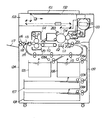
トナー補給装置100にはトナー撹拌送り装置45が付設されている。図11及び図12に示すように、トナー補給開口33を下から覆うようにしてケース48がトナー補給装置本体54に固定されている。ケース48はトナー補給装置100の長手方向とほぼ同長であり、このケース48内には長手方向にトナー搬送部材としての撹拌スクリュー46,47が回転駆動されるように配設されてケース48に支持されている。
【0128】
上記撹拌スクリュー46,47は隔壁48aで仕切られており、長手方向においてトナー補給開口33とは反対側で隔壁48aに設けられた開口によって、斜め上側の撹拌スクリュー46を設けた室48Aと下側の撹拌スクリュー47を設けた室48Bは連通せしめられている。ケース48には、長手方向でトナー補給開口33と同じ側に現像器201へ通ずるトナー排出口48bが設けられている。
【0129】
上記において、トナー補給開口33からトナーが補給されると、回転しているトナー撹拌スクリュー46は室48A内をトナー補給開口33側から長手方向で室48Aの反対側へトナーを送りながらこれを攪拌し、室48Aの前記反対側では隔壁48aに設けられた不図示の開口を通じて室48Bへトナーを落とす。下側のトナー撹拌スクリュー47はトナー撹拌スクリュー46のトナー送り方向とは反対方向へトナーを攪拌しながらこれを送り、トナー排出開口48bから現像装置201へトナーを補給する。
【0130】
(定位置装着手段)
ハンドルの回動からシャッタ開閉に至る駆動力伝達経路において、高精度の部品を用いないで且つコストを掛けないで構成しようとすれば、ギヤ等のバックラッシュやその他の部位に駆動系のガタ及び歪みが生じてしまうことは避け難い。従って、入力ストロークに対する出力ストロークが1:1に対応せず、シャッタを開いてから再び閉じてもシャッタが元の位置に戻らないことがある。このような状態のトナー補給容器を装置本体から抜き出し、そのままトナー補給容器1を再び装着してシャッタの開閉を行うと、シャッタが元に戻らない分が蓄積していき、戻らない量が増大していく。
【0131】
本体シャッタと容器シャッタとを一体的に係合させる構成においては、シャッタの位置ずれによってトナー補給容器が装置本体から抜き出せなくなったり、本体シャッタの位置ずれのために新品の(シャッタが本来の位置にある)トナー補給容器が装着できなくなったりすることがある。
【0132】
このような問題は、ハンドル及びシャッタが装置本体側の中継ギヤと係合する前に予めハンドルを開方向へ所定角度回動させ、ハンドルを閉方向へ回動させる際にはこの分も含めて戻すことによってバックラッシュやガタ等によるストロークロスを吸収し、シャッタを確実に元の位置まで戻すようにすることによって解決される。
【0133】
次に、このような手段を具体的に説明する。
【0134】
図1、図2、図33及び図34に示すように、ハンドル15上にはハンドル突起61が設けられている。このハンドル突起61の形状は平面図(下方から上方に向かって見ている下視図)で示す図41〜図43に示すようにカムフォロワを成しており、作用面61aは図41〜図43の上下方向の幅が狭く、トナー補給装置本体54の上部54bの天板下面に設けられたカムである本体突起62に接触可能となっている。尚、突起61,62はカム対偶を構成している。
【0135】
本体突起62は山形のカム面を有しており、このカム面のリフトはトナー補給装置本体54の中心(下部54aの半径の中心)に対して生ずる中心角がトナー補給容器1とトナー補給装置100間の回動方向のガタを取り、トナー補給容器1をトナー補給装置100に対して所定角度の挿入位置とするのに必要な程度となっている。尚、この中心角は6°以上となっており、本実施の形態では6°に設定している。
【0136】
次に、上記ハンドル突起61と本体突起62の関係位置を作用と共に説明する。
【0137】
トナー補給容器1をトナー補給装置100へ挿入していくと、図33及び図43に示すように、ハンドル突起61は本体突起62のリフト=0の位置で係合開始位置へ来る。このとき、ハンドル15の駆動力伝達係合部15aと本体側の駆動力受側係合部材21aとはトナー補給容器1のトナー補給装置100への挿入方向に距離L1だけ離れている。この距離L1が本体突起62で最大リフトをハンドル突起61に生じさせる行程L2に等しい。
【0138】
図33及び図43に示す状態からトナー補給容器1をトナー補給装置100へ挿入すると、ハンドル突起61は本体突起62上を滑ってハンドル15を回転させる。そこで、図42に示すように、ハンドル15が6°回転してハンドル突起61が本体突起62のカムトップと接触した状態においてハンドル15の係合部15aとトナー補給装置100の係合部21aの歯端が一致する。尚、これらの係合部15a,21aの歯端が一致する僅か前には本体側係合部21gに対して容器シャッタ16の係合部16dの歯端は一致しているため、係合部21gに対する係合部16dの噛み合いは極めて僅か先行する。
【0139】
更に、トナー補給容器1をトナー補給装置100へ挿入すると、図41に示すように、ハンドル15の駆動力伝達側係合部15aとトナー補給装置100の駆動力受側係合部21aが噛み合う。
【0140】
一方、図10に示す駆動力伝達側係合部21gに対してシャッタ16の駆動力受側係合部16dも全歯幅に亘って噛み合うため、図42に示す状態から図41に示す状態へトナー補給容器1が移動する際、ハンドル15は非回転であって、図41に示すようにハンドル突起61は本体突起62のカムトップに対応した位置にある。
【0141】
上述のようにハンドル突起61が本体突起62により変位させられることによってハンドル15は6°回転する。このため、ハンドル15と第1フランジ12に設けられた係合部分にはガタを持たせてある。即ち、図7及び図8に示すように、ロック部材51の凹部51bと第1フランジ12のロック突起12h間及びハンドル15の溝15k,15mと第1フランジ12の係合リブ51dとの間にはハンドル15が6°回転し得る周方向のガタが設けられている。
【0142】
又、上記ハンドル15をハンドル突起61と本体突起62で回動させる前に容器シャッタ16を本体シャッタ34に所定位置で係合させておくため、図39及び図40に示すように、トナー補給装置本体100の下部54aの内周に容器シャッタ16の長手方向の縁(端面)と摺動する位置決め凸部63が設けられている。この凸部63は山形のカム面を有し、カムトップはトナー補給装置本体54の下部54aの周方向について容器シャッタ16が嵌入する本体シャッタ34の凹部の一端側の面34b1が所定の一定位置とされる位置と同位置にある。
【0143】
トナー補給容器1をトナー補給装置100へ挿入すると、容器シャッタ16の面取り部16qが凸部63に当たって容器シャッタ16の位置が一定位置に規制される。容器シャッタ16の片側の側縁16r1と凸部63が摺動して本体シャッタ34に向かい、本体シャッタ34の一方の面34b1の端部の面取り部34b2に容器シャッタ16の面取り部16pが当たり、容器シャッタ16に対して本体シャッタ34は位置を規制され、更に容器シャッタ16は進んで容器シャッタ16の面取り部16qが本体シャッタ34の面取り部34b3と係合して本体シャッタ34の両側の面34b1間に容器シャッタ16が侵入して図39に示すようになった状態でトナー補給装置100側の係合部21a,21gに対してトナー補給容器1側の係合部15a,16dが噛み合い、歯幅方向での所定幅が噛み合った状態で容器シャッタ16と本体シャッタ34は図40に示すようになり、容器シャッタ16の側縁16rの装着方向後方の面取り部16sが凸部63から離れた位置となる。
【0144】
この作用において、容器シャッタ16のトナーコンテナ11のトナー排出開口11aを開閉するための抵抗は、パッキン部材35が容器シャッタ16を加圧しているため、本体シャッタ34の開閉抵抗に比較すると十分大きくなっている。従って、凸部63が容器シャッタ16の位置を定め、容器シャッタ16が本体シャッタ34の位置決めを行う。
【0145】
以上の構成と作用により、本体シャッタ34と容器シャッタ16は係合された際は一定位置となっており、この状態でユーザーがハンドル15をトナー補給容器1のトナー補給装置100への挿入方向から見て時計方向へ84°回動させると、各シャッタ16,34も開く方向へ50°回動して全開する。
【0146】
トナー補給容器1をトナー補給装置100から取り外す際は、ユーザーがハンドル15を上記と逆に反時計方向へ90°回動させると、各シャッタ16,34は閉じる方向へ50°回動して元の位置へ戻る。
【0147】
ここで、ハンドル15の回動角度と各シャッタ16,34の回動角度が開と閉で対応しないが、これはギヤのバックラッシュ、ハンドル15、シャッタ16,34、シャフト等の歪みや曲がり、トナー補給容器1がトナー補給装置100に対して回動すること等が原因であり、予め6°予回動として空転させておくことによって、これらを吸収して各シャッター16,34を元の位置まで戻すことができる。
【0148】
トナー補給容器1をトナー補給装置100から引き抜く際にも、ハンドル突起61と本体突起62との係合により、装着時と同様に開方向へ6°の予回動が行われ、そのトナー補給容器1を再度使用する場合に備えるようになっている。又、万一ハンドル15を反時計方向へ90°回動させないで(例えば84°だけ回動)トナー補給容器1を取り外そうとする場合には、容器シャッタ16と本体シャッタ34とは本来の位置まで戻り切れていない可能性がある。
【0149】
しかし、トナー補給容器1を引き出すことによって容器シャッタ16の面取り部16sとトナー補給装置100の凸部63とが係合して容器シャッタ16と本体シャッタ34を強制的に本来の位置へ戻すようになっているため、前記不都合は回避される。
【0150】
図45に容器シャッタ16を閉めた状態でのトナー排出開口11aの拡大断面を示すが、図示のように、トナー排出開口11aを囲むようにトナーコンテナ11の外側表面にパッキン部材35が貼付されている。
【0151】
尚、パッキン部材35としては、柔らかい弾性体が好ましく、材質として具体的にはシリコン、ウレタン、発泡ポリエチレン等のゴムやスポンジ、好ましくは硬度20°〜70°、圧縮永久歪み10%以下、セルサイズ60〜300μm、密度が0.15〜0.50g/cm3 である低発泡ポリウレタンを用いる。又、パッキン部材35の厚さとしては、シール性や容器シャッタ16の開封強度を考慮すると好ましくは1〜5mm、より好ましくは2〜4mmである。そして、パッキン部材35は、高いシール性を維持するために容器シャッタ16と該パッキン部材35間の距離を縮める等して、好ましくは5〜50%圧縮して用い、より好ましくは30〜40%圧縮して用いる。本実施の形態では、厚さ3mmの低発泡ポリウレタンを容器シャッタ16とパッキン部材35間の距離を2mmにすることで33%圧縮して用いた。
【0152】
パッキン部材35のトナー排出開口11aの長手方向の縁に沿う開口縁端35aは容器シャッタ16と接触しないように構成されている。開口縁端35aと容器シャッタ16間の隙間距離は、好ましくは0.1〜2mm、より好ましくは0.3〜1mmになるように設定し、本実施の形態では隙間間隔を0.5mmとした。又、本実施の形態では、パッキン部材35の貼付け面をトナー排出開口11a内へ向かって傾斜させることによって容器シャッタ16に開口縁端35aを接触させないようにしているが、その傾斜角度は好ましくは10〜15°、より好ましくは20〜40°とし、本実施の形態では傾斜角度30°とした。尚、最初から開口縁端35aを容器シャッタ16に接触しない形状に構成し、それを貼付しても良い。
【0153】
尚、パッキン部材35はトナー排出開口11aの周縁に接着等で固定するが、その際、図46に示すようにパッキン部材35の開口穴側からスリット状の切り込み35bを入れておくと、トナー排出開口11aの長手方向の縁の斜面部分に追随し易くなる。又、2色成形によりトナーコンテナ11とパッキン部材35とを一体成形できれば尚好ましい。
【0154】
以上のような構成を有するトナー補給容器1をトナー補給装置100に装着し、ハンドル15の回動による容器シャッタ16の開閉操作を数回繰り返した結果、パッキン部材35及びシール部材41の捲れ及び破損は発生しなかった。
【0155】
比較例として、図47に開口縁端35aに容器シャッタ16及びシール部材41を接触させる例を示す。このような構成を有するトナー補給容器1をトナー補給装置100に装着し、ハンドル15の回動による容器シャッタ16の開閉操作を数回繰り返した結果、パッキン部材35の開口縁端35a及びシール部材41の捲れ及び破損が発生した。
【0156】
<実施の形態2>
図48に容器シャッタ16を閉めた状態でのトナー排出開口11aの拡大断面を示す。トナー補給容器本体11上のパッキン部材35の貼付け面が円筒面で構成されている。それ以外の構成は実施の形態1と同じである。
【0157】
以上のような構成を有するトナー補給容器1をトナー補給装置100に装着し、ハンドル15の回動による容器シャッタ16の開閉操作を数回繰り返した結果、パッキン部材35及びシール部材41の捲れ及び破損は発生しなかった。
【0158】
パッキン部材35の貼付け面が円筒面で構成されている場合、該パッキン部材35の開口縁端35aは外円方向に向かって突出し易く、平面で構成されている場合と比較して開口縁端35aと容器シャッタ16及びシール部材41が接触し易い構成になっている。本実施の形態は図23に示すようにこのような懸念をも解消したものであり、本発明の効果を得るには最も好ましい実施の形態である。
【0159】
<実施の形態3>
図49に容器シャッタ16を閉めた状態でのトナー排出開口11aの拡大断面を示す。容器シャッタ16はトナー補給容器本体11内に設けられており、トナー補給容器本体11上のパッキン部材35の貼付け面が凹面で構成されている。それ以外の構成は実施の形態1と同じである。
【0160】
以上のような構成を有するトナー補給容器1をトナー補給装置100に装着し、ハンドル15の回動による容器シャッタ16の開閉操作を数回繰り返した結果、パッキン部材35及びシール部材41の捲れ及び破損は発生しなかった。
【0161】
<実施の形態4>
図50に容器シャッタ16を閉めた状態でのトナー排出開口11aの拡大断面を示す。パッキン部材35の長手方向の外縁端35cは容器シャッタ16と接触しないように構成されている。本実施の形態では、パッキン部材35の貼付け面を約30°傾斜させることによって容器シャッタ16に外縁端35cを接触させないようにしているが、最初から外縁端35cを容器シャッタ16に接触しない形状に構成し、それを貼付しても良い。それ以外の構成は実施の形態1と同じである。
【0162】
以上のような構成を有するトナー補給容器1をトナー補給装置100に装着し、ハンドル15の回動による容器シャッタ16の開閉操作を数回繰り返した結果、パッキン部材35及びシール部材41の捲れ及び破損は発生しなかった。
【0163】
以上のような構成により、容器シャッタ16をトナー補給容器本体11に組み込む際や、容器シャッタ16の開封時に該容器シャッタ16及びシール部材41がパッキン部材35に接しない位置まで退避させるように構成されている場合においても、パッキン部材35及びシール部材41の捲れ及び破損を防止することができる。
【0164】
【発明の効果】
以上の説明で明らかなように、本発明によれば、電子写真画像形成装置本体にトナーを供給するためのトナー補給容器を、前記電子写真画像形成装置本体に供給するためのトナーを収納するトナー補給容器本体と、該トナー補給容器本体に収納されているトナーを排出するためのトナー補給容器本体に設けられたトナー排出開口と、該トナー排出開口を開封可能に封止するための容器シャッタと、前記トナー排出開口の周囲に固定されて前記トナー排出開口と前記容器シャッタ間で圧縮されることによってシール性を維持するパッキン部材とを有し、前記パッキン部材の前記容器シャッタの開閉方向と交差する開口部縁端が少なくとも前記容器シャッタに接触しないように構成したため、容器シャッタの開封時におけるパッキン部材の捲れと破損を防ぐことができるという効果が得られる。
【図面の簡単な説明】
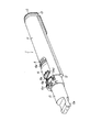
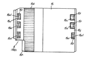
【図1】トナー補給容器を装着方向手前側から見た斜視図である。
【図2】トナー補給容器を装着方向反対側から見た斜視図である。
【図3】トナー補給容器を裏返して見た斜視図である。
【図4】トナー補給容器の分解斜視図である。
【図5】トナー補給容器の縦断面図である。
【図6】容器シャッタの駆動系を示す側面展開図である。
【図7】ハンドルロックを示す側面図である(ロック状態)。
【図8】ハンドルロックを示す側面図である(解除状態)。
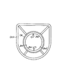
【図9】トナー補給容器の背面図である。
【図10】トナー補給容器の駆動力伝達部材を示す斜視図である。
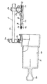
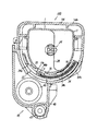
【図11】トナー補給容器の正断面図である(シャッタ閉)。
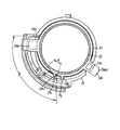
【図12】トナー補給容器の正断面図である(シャッタ開)。
【図13】トナー補給容器の正断面図である(シャッタ開閉中)。
【図14】図11の一部拡大図である。
【図15】図12の一部拡大図である。
【図16】図13の一部拡大図である。
【図17】図16に対応する比較例を示すトナー補給容器の正断面図である。
【図18】図13に対応する比較例を示すトナー補給容器の正断面図である。
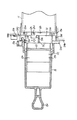
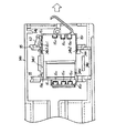
【図19】トナー補給容器が装着されていないトナー補給装置の正断面図である。
【図20】容器シャッタの正断面図である。
【図21】図20(a)の直角方向から見た断面図である。
【図22】容器シャッタの斜視図である(ミシン目)。
【図23】容器シャッタの斜視図である(屈曲)。
【図24】容器シャッタの斜視図である(突片)。
【図25】容器シャッタのシール部材の斜視図である(ミシン目)。
【図26】容器シャッタのシール部材の斜視図である(溝)。
【図27】トナー補給装置の本体シャッタ部を示す斜視図である。
【図28】電子写真画像形成装置の縦断面図である。
【図29】電子写真画像形成装置の斜視図である。
【図30】ハンドルロック部材の側面図である。
【図31】ハンドルロック部材の正面図である。
【図32】ハンドルロック部材の底面図である。
【図33】トナー補給装置へトナー補給容器を装着する作用を示す正面図である。
【図34】トナー補給装置へトナー補給容器を装着する作用を示す正面図である。
【図35】トナー補給装置へトナー補給容器を装着する作用を示す正面図である。
【図36】ハンドルを取り外したトナー補給容器をトナー補給装置へ装着した状態を示す正面図である。
【図37】ハンドルを取り外したトナー補給容器をトナー補給装置へ挿入した状態を示す正面図である。
【図38】ハンドルロック部材の位置のトナー補給容器の正断面図である。
【図39】トナー補給装置の水平断面図である。
【図40】トナー補給装置の水平断面図である。
【図41】定位置装着手段の作用を示す模式図である。
【図42】定位置装着手段の作用を示す模式図である。
【図43】定位置装着手段の作用を示す模式図である。
【図44】容器シャッタの平面図である。
【図45】トナー排出開口の拡大断面図である(シャッタ閉)。
【図46】シャッタを取り外したトナー排出開口の水平断面図である。
【図47】トナー排出開口の拡大断面図である(シャッタ閉)。
【図48】トナー排出開口の拡大断面図である(シャッタ閉)。
【図49】トナー排出開口の拡大断面図である(シャッタ閉)。
【図50】トナー排出開口の拡大断面図である(シャッタ閉)。
【符号の説明】
1 トナー補給容器
11 トナーコンテナ(トナー補給容器本体)
11a トナー排出開口
16 容器シャッタ
35 パッキン部材
35a 開口端縁
35b 切り込み
41 シール部材
42 可撓性フィルム(低摩擦抵抗材料)
124 電子写真画像形成装置本体
[0001]
BACKGROUND OF THE INVENTION
The present invention relates to a toner supply container for supplying toner to an electrophotographic image forming apparatus such as an electrophotographic photocopier or a printer.
[0002]
[Prior art]
An electrophotographic image forming apparatus such as an electrophotographic copying machine or a laser beam printer forms an electrostatic latent image on a photosensitive drum by selectively exposing a uniformly charged photosensitive drum. The image is developed with toner to form a toner image. Thereafter, the toner must be replenished every time the toner runs out. Here, the toner replenishing container for replenishing toner to the electrophotographic image forming apparatus includes a batch replenishment type container that replenishes all of the stored toner in a toner receiving container of the image forming apparatus main body at once, and an image forming apparatus main body. After mounting the container, the container is roughly divided into a stationary container that holds the container as it is. The stationary container gradually replenishes the developing device with toner until the toner is used up.
[0003]
In recent years, there has been a tendency that a stationary toner supply container is used in order to reduce the size of the image forming apparatus. A shutter member is provided to prevent toner remaining in the container from being scattered from the discharge opening when the toner supply container is replaced.
[0004]
[Problems to be solved by the invention]
However, in order to maintain the sealing performance between the shutter member and the toner discharge opening, and to prevent toner leakage in the toner supply container body due to a drop impact or the like, a packing member made of a soft elastic body is used as a sealing member. When affixed to the outer surface of the toner supply container body so as to surround the toner discharge opening, the edge of the opening of the packing member that intersects the opening / closing direction of the shutter member swells due to sliding with the shutter member when the toner discharge opening is opened / closed. The opening strength of the shutter member may increase, and in the worst case, the packing member may be damaged.
[0005]
Further, the outer edge of the packing member intersecting with the opening / closing direction of the shutter member is swollen by sliding with the shutter member when the toner discharge opening is opened / closed or when the shutter member is incorporated into the toner supply container body, and the opening strength is also increased. There is also a case.
[0006]
The present invention has been made in view of the above problems, and an object of the present invention is to provide a toner replenishing container that can prevent the packing member from curling and breaking when the container shutter that seals the toner discharge opening is opened. There is.
[0007]
[Means for Solving the Problems]
  To achieve the above purposebook ofThe invention relates to an electrophotographic image forming apparatus main body.Toner supply deviceIn a toner supply container for supplying toner to
  A toner supply container main body for storing toner to be supplied to the electrophotographic image forming apparatus main body, and a toner supply container main body for discharging the toner stored in the toner supply container main bodyCylindrical surfaceA toner discharge opening provided in the container, a container shutter that moves along the toner supply container body and seals the toner discharge opening so as to be openable, and a periphery of the toner discharge openingCylindrical surfaceA packing member that is fixed to the periphery of the toner discharge opening and is compressed between the container shutter and maintains a sealing property,
  The container shutter is configured to engage with a concave portion of a main body shutter that opens and closes a toner supply port provided in the toner supply device, and is configured to open and close in conjunction with the main body shutter.
  Provided on the surface of the container shutter on the toner supply container main body side, and extends from the downstream end of the container shutter in the shutter closing direction to the downstream in the shutter closing direction, and between the container shutter and the main body shutter. A sealing member for covering the gap formed in the
  The downstream end of the container shutter and the seal member in the shutter closing direction is configured to pass over the edge of the toner discharge port that intersects the opening / closing direction of the container shutter when the container shutter is opened / closed. ,
  The opening edge of the packing member that intersects the opening / closing direction of the container shutter is at least the container shutter.And the sealing memberSo as not to touchThe fixing surface of the packing member in the vicinity of the edge intersecting the opening / closing direction of the container shutter is inclined so as to be lowered toward the toner discharge opening.It is characterized by that.
[0023]
DETAILED DESCRIPTION OF THE INVENTION
Embodiments of the present invention will be described below with reference to the accompanying drawings.
[0024]
Each embodiment described below relates to a toner replenishing container for supplying toner to an electrophotographic image forming apparatus main body, and the toner replenishing container includes a toner accommodating portion that accommodates toner and the toner accommodating container. A toner discharge opening for discharging the toner stored in the unit, an opening / closing member for sealing the toner discharge opening so as to be openable, and opening the toner discharge opening when the image forming apparatus body is mounted. For this purpose, a driving force receiving portion for receiving a driving force for moving the opening / closing member is provided.
[0025]
<Embodiment 1>
(Electrophotographic image forming apparatus)
FIG. 28 is a longitudinal sectional view of the electrophotographic image forming apparatus equipped with the toner supply container according to Embodiment 1 of the present invention.
[0026]
In the electrophotographic image forming apparatus shown in FIG. 28, a manuscript 101 is placed on a platen glass 102 by an operator, and a light image of the manuscript 101 is formed on a photosensitive drum 104 by a plurality of mirrors and lenses of an optical unit 103. Is done.
[0027]
On the other hand, of the recording media (paper, OHP sheets, etc., hereinafter referred to as paper) P loaded in the feeding cassettes 105 to 108, the size based on information input by an operator from an operation unit (not shown). Paper P is selected. Then, among the feed rollers 105A to 108A, the rollers (105A to 108A) corresponding to the selected feed cassette (105 to 108) rotate. Then, one sheet of paper P sent out from the paper feed cassettes 105 to 108 is transported between the registration rollers 110 via the transport unit 109. The registration roller 110 conveys the paper P to the photosensitive drum 104 in synchronization with the rotation of the photosensitive drum 104 and the scanning timing of the optical unit 103. Then, the paper P receives the transfer of the toner image on the photosensitive drum 104 by the transfer unit 111, and the paper P on which the toner image is transferred is separated from the photosensitive drum 104 by the separation unit 112. Then, the paper P is transported by the transport unit 113 and reaches the fixing unit 114, where the toner image is fixed on the paper P by heat and pressure. afterwards,
1) In the case of single-sided copying, the paper P passes through the reversing unit 115 and is discharged to the tray 117 by the discharge roller 116.
2) In the case of multiple copying, the paper P is conveyed to the conveyance units 119 and 120 by the flapper 118 of the reversing unit 115 and reaches the registration roller 110. Thereafter, the paper P is discharged to the tray 117 through the image forming unit, the conveyance unit 113, and the fixing unit 114 in the same manner as described above.
3) In the case of duplex copying, a part of the paper P passes through the reversing unit 115 and is temporarily discharged by the discharge roller 116 to the outside of the apparatus. Thereafter, after the end of the paper P passes through the flapper 118, the discharge roller 116 is rotated in the reverse direction. Then, the paper P is conveyed again into the apparatus. The sheet P is conveyed to the conveyance units 119 and 120 and reaches the registration roller 110, and the sheet P is discharged to the tray 117 through the image forming unit, the conveyance unit 113, and the fixing unit 114 as described above.
[0028]
In the electrophotographic image forming apparatus having the above configuration, a developing device 201, a cleaning unit 202, and a primary charging unit 203 are arranged around the photosensitive drum 104. The developing device 201 develops the electrostatic latent image formed on the photosensitive drum 104 using toner, and the toner supply container 1 for supplying the toner to the developing device 201 is detachably attached to the apparatus main body 124. Has been.
[0029]
Here, the developing device 201 has a developing roller 201a disposed with a minute gap (about 300 μm) between the developing device 201 and the photosensitive drum 104. During development, the developing device 201 is thinned around the developing roller 201a by the developing blade 201b. A toner layer is formed. The electrostatic latent image formed on the photosensitive drum 104 is developed by applying a developing bias to the developing roller 201a.
[0030]
The charging unit 203 charges the photosensitive drum 104, and the cleaning unit 202 removes toner remaining on the photosensitive drum 104. When the toner decreases due to development, the toner is replenished sequentially from the toner replenishing device 100.
[0031]
Here, the replacement of the toner supply container 1 will be described.
[0032]
First, the notification unit 124a shown in FIG. 29 is notified that the toner in the toner replenishing device 100 has run out. Then, the operator opens the opening / closing member 121 that covers the opening 122 that opens in the apparatus main body 124 shown in FIG. A holder 31 (specifically, a toner replenishing device main body 54) on which the toner replenishing container 1 is detachably mounted is provided behind the opening 122. The toner supply container 1 is inserted into the holder 31 along its longitudinal direction. At this time, the toner supply container 1 is guided to a predetermined position by being guided by a guide provided along the longitudinal direction of the holder 31. When the operator rotates the handle 15 of the toner supply container 1 after inserting the toner supply container 1, the toner in the toner supply container 1 is supplied to the developing device 201. When the operator closes the opening / closing member 121, the power switch is turned on and the image forming apparatus can be driven.
[0033]
That is, when a sensor (not shown) in the developing device 201 issues a signal indicating that the toner in the developing device 201 has decreased, the toner conveying screws 46 and 47 shown in FIG. It is supplied to the developing device 201. When the amount of toner in the developing device 201 reaches a predetermined amount, the toner conveying screws 46 and 47 are stopped. This operation is repeated.
[0034]
When the toner in the case 48 eventually decreases, a sensor (not shown) in the case 48 generates a signal indicating that the toner has decreased, and the conveying member 29 in the toner supply container 1 rotates to feed the toner into the case 48. When the toner amount in 48 reaches a predetermined amount, the conveying member 29 stops. This operation is repeated. If toner is not supplied even if the sensor in the case 48 issues the signal, a notification that the toner supply container 1 is to be replaced is displayed on the notification unit 124a (see FIG. 29).
[0035]
(Toner supply container)
The toner supply container 1 (see FIGS. 1 to 3) according to the present embodiment is mounted on a toner supply device 100 in the image forming apparatus. This toner replenishing container 1 is a so-called stationary type (built-in) that is left as it is, and gradually supplies toner to the developing unit until the stored toner is used up. The application of the present invention is not limited to a stationary toner supply container, and for example, the present invention is also applied to a so-called batch supply type toner supply container.
[0036]
Thus, as shown in FIG. 4, the toner replenishing container 1 includes a toner container 11 that is a toner storage unit, and a first flange 12 and a second flange 13 that are attached to both ends of the toner container 11 in the longitudinal direction. The cap 14 is fitted into the first flange 12 and the handle 15 is fitted into the first flange 12 so as to be rotatable. A container shutter 16 that opens and closes the toner discharge opening 11 a of the toner container 11 is provided. In the toner container 11, a toner conveying member 29 is provided as a toner conveying means (see FIG. 5).
[0037]
(Toner container)
As shown in FIG. 4, the toner container 11 has a shape in which a rectangular portion 11h is connected to an arc portion 11g whose cross section perpendicular to the longitudinal direction is close to a semicircle, and the inside thereof is a hollow cylinder having a single space. A toner is stored in the inside of the member. A toner discharge opening 11a is provided on the outer peripheral surface of the arc portion 11g, and shutter support members 11e are provided around both sides of the toner discharge opening 11a in the longitudinal direction. The container shutter 16 is supported by the shutter support member 11e to close the toner discharge opening 11a (see FIG. 11), and the container shutter 16 opens from the closed position to open the toner discharge opening 11a (see FIG. 12). And can take.
[0038]
Further, linear guide portions 11k are provided in the longitudinal direction on both sides of the toner container 11, and the guide portions 11k are used when the toner supply container 1 is attached to and detached from the toner supply device 100 provided in the apparatus main body 124. The toner supply container 1 is regulated so as to advance and retreat straight.
[0039]
In the present embodiment, the shape of the toner container 11 is a cylindrical shape in which the lower part of the cross section is semicircular and the upper part is rectangular. However, the shape is not limited to this. For example, the cross section intersecting the longitudinal direction may be a circle, an ellipse, a shape having a corner, or the like. Further, the configuration and the number of parts of the toner container 11 are not particularly limited.
[0040]
By the way, the toner container 11 is filled with powder toner, and as the toner, for example, black toner, color toner, one-component magnetic toner, one-component non-magnetic toner or the like is appropriately selected.
[0041]
(Configuration of first and second flanges)
The first flange 12 and the second flange 13 are each formed in a hollow cylindrical shape that fits exactly on the inner periphery of the end of the toner container 11, and these are fitted and fixed to both ends of the toner container 11 in the longitudinal direction. Thereafter, the toner container 11 is sealed.
[0042]
Here, the first flange 12 includes an end plate 12b, and a cylindrical peripheral wall portion 12e having the same center as the center of the arc portion 11g of the toner container 11 following the end plate 12b, and the peripheral wall portion 12e. Through the inside, the first flange 12 is provided with a toner filling port 12a. The second flange 13 has an end plate 13a.
[0043]
The first flange 12 and the second flange 13 may be integrated with the toner container 11 or a part of the toner container 11. That is, the first flange 12 and the second flange 13 constitute a part of the toner container 11 and form one toner storage container main body.
[0044]
Further, the first flange 12 is provided with a toner filling port 12a for filling the toner at a position which is the end portion (upstream side) in the container insertion direction, and the inside of the toner filling port 12a has a radial shape. Ribs 12c are provided (see FIGS. 36 and 37). A shaft hole 12d for pivotally supporting a toner conveying member 29 described later is provided at the center. A handle 15 described later is fitted to a cylindrical peripheral wall portion 12e around the toner filling port 12a, and the toner filling port 12a is sealed with a cap 14 after the toner is filled. The first flange 12 is joined and integrated with the toner container 11.
[0045]
Further, the end plate 13a of the second flange 13 is used to insert a driving force receiving portion (for example, a coupling) that supports the toner conveying member 29 from the outside of the toner container 11 and transmits the driving force. A hole 13c is formed, and a cylindrical peripheral wall portion 13d (see FIGS. 4 and 5) for supporting the outer peripheral surface of the driving force receiving portion is provided around the hole 13c.
[0046]
(handle)
The handle 15 has a cylindrical shape. One end of the handle 15 has a tip-shaped handle 15e. The other end of the handle 15 is hollow and has a two-stage cylindrical shape. The side toward the toner container 11 is open. . The handle 15 has a middle inner periphery 15h that is rotatably fitted to a handle support portion 12f that is a part of a cylindrical peripheral wall portion 12e provided at one end of the toner container 11 (see FIGS. 7 and 7). (See FIG. 8). An engaging portion 15 a that transmits driving force is provided on the outer peripheral surface of the handle 15.
[0047]
When the toner replenishing container 1 is inserted into the toner replenishing device 100, the engaging portion 15a is engaged with the engaging portion 21a of the driving force transmitting member 21 provided in the toner replenishing device 100 as shown in FIGS. It has an engageable segment gear shape. The engaging portion 15a can be engaged with the engaging portion 21a by a series of operations for inserting the toner supply container 1.
[0048]
As shown in FIGS. 6 and 10, the driving force transmission member 21 has a driving force receiving side engaging portion 21 a and a driving force transmitting side engaging portion 21 b at both ends of a shaft 21 s rotatably supported by the toner replenishing device 100. have. Here, the engaging portions 21a and 21b are gears and have a plurality of teeth. In the present embodiment, the driving force receiving side engaging portion 21a is composed of one gear. However, as long as the driving force receiving mechanism is provided, there is no particular limitation on the configuration and the number of gears.
[0049]
In the present embodiment, the driving force transmission side engaging portion 21b meshes with the driving force receiving side engaging portion 16d, which is a segment gear, via an idler gear as the driving force transmission side engaging portion 21g. In the present embodiment, the driving force transmission member 21 (that is, the shaft 21s, the engaging portions 21a and 21b, and the engaging portion 21g) is provided on the apparatus main body 124 side.
[0050]
(Toner conveying member)
As shown in FIG. 5, one end of the transport shaft 27 that supports the toner transport member 29 is rotatably supported in the shaft hole 12d (see FIG. 37). The transport shaft 27 is pivotally supported so that rotational force is transmitted by a coupling 26a fixed to the other end. The toner conveying member 29 has a conveying blade 28 made of a flexible member fixed to the conveying shaft 27. The coupling 26a is rotatably supported by the toner container 11.
[0051]
The transport blade 28 includes a plurality of blades having claw portions 28a that rub against the inner peripheral surface of the toner container 11 and whose tip side is inclined according to the rotation direction with respect to the toner transport discharge opening 11a. For this reason, the toner in the toner container 11 can be sent toward the toner discharge opening 11a.
[0052]
By the way, the toner discharge opening 11a is disposed on the front side (upstream side) when viewed from the insertion direction of the toner supply container 1 with respect to the apparatus main body 124. Accordingly, all the claw portions 28a face the same direction. Depending on the arrangement position of the toner discharge opening 11a, the directions of the claw portions 28a may not be the same direction, but may be arranged in each direction as appropriate. Further, when the toner supply container 1 is mounted on the toner supply device 100, the coupling 26a meshes with a drive side coupling 44 (see FIG. 19) provided in the toner supply device 100 to obtain a driving force to obtain toner. The conveyance member 29 is rotationally driven.
[0053]
Note that the toner conveying member 29 is not necessarily required as long as the toner in the toner container 11 can be conveyed to the toner discharge opening 11a. However, the toner can be reliably supplied by providing the toner conveying member 29.
[0054]
Next, FIG. 9 shows an end portion on the side receiving the driving force of the toner supply container 1. A coupling 26a as a driving force receiving member is rotatably supported on the end surface of the toner container 11, and both ends in the axial direction of the coupling 26a constitute a shaft coupling. In the toner container 11, the coupling 26 a is connected to one end of the transport shaft 27 of the transport member 29.
[0055]
A rotational force receiving portion is provided outside the toner container 11, and this rotational force receiving portion transmits the rotational force provided in the toner replenishing device 100 when the toner replenishing container 1 is attached to the apparatus main body 124. And a coupling 44 for connecting. As shown in FIG. 9, the rotational force receiving portion is composed of radial protrusions 26a1, and the protrusions 44a (see FIG. 19) of the drive side coupling 44 engage with the recesses 26a2 between the protrusions 26a1. Connected.
[0056]
(Container shutter)
As shown in FIG. 4, slide portions 16f are provided at both ends in the longitudinal direction of the container shutter 16, and the slide portions 16f are shutter support members as guide members provided on both sides in the longitudinal direction of the toner discharge opening 11a. 11e is engaged. The container shutter 16 slides in the circumferential direction of the toner container 11 so that the toner discharge opening 11a can be opened and closed. That is, the cross section of the container shutter 16 perpendicular to the longitudinal direction of the toner supply container 1 has an arc shape, and has a shape along the outer peripheral surface of the toner container 11. The slide section 16f and the shutter support member 11e have a bowl-shaped cross section cut by a plane including the center line of the arc of the container shutter 16 (see FIG. 6), and the shutter support member 11e has a bowl-shaped cross section. It is continuous over the entire length.
[0057]
As shown in FIGS. 20, 21, 39, 40, and 44, the slide portion 16 f has protrusions 16 u corresponding to a plurality of through holes 16 t provided in the circumferential direction of the container shutter 16. It is formed as. As shown in FIG. 44, an H or T-shaped protrusion 16u1 is provided on the surface of the tip 16u that contacts the shutter support member 11e, and the tip 16u has a container shutter 16 fixed to the elastic packing member 35. It has a function as a spring member so that it may contact with the pressure of. Therefore, even if the pressing force received from the elastic packing member 35 changes depending on the position when the container shutter 16 is opened and closed, the pressing force is compensated by the deformation of the plurality of hooks 16u (see FIG. 21).
[0058]
When the toner replenishing container 1 is mounted on the toner replenishing device 100, the container shutter 16 receives a rotational force that can be engaged with a gear as the driving force transmitting side engaging portion 21g as shown in FIG. As a driving force receiving side engaging portion 16d. The driving force receiving side engaging portion 16d has a plurality of teeth, and can be engaged with the driving force transmitting side engaging portion 21g by a series of operations of inserting the toner replenishing container 1 into the toner replenishing device 100. is there.
[0059]
By the way, the driving force receiving side engaging portion 16 d is carved on the outer surface 16 m of the container shutter 16. Here, the segment gear-shaped tooth tip circle diameter of the driving force receiving side engaging portion 16d and the outer diameter of the container shutter 16 other than the engaging portion 16d are set substantially the same, and the space in the height direction is saved. ing. Since the driving force receiving side engaging portion 16d is engaged with and disengaged from the driving force transmitting side engaging portion 21g, the engaging portion 16d is provided on the outer surface near the edge of the container shutter 16 near the coupling 26a. ing. Thus, the driving force receiving side engaging portion 16d is disengaged from the driving force transmitting side engaging portion 21g when the container shutter 16 is positioned at the closed position.
[0060]
Further, the driving force transmitting side engaging portion 21g and the driving force receiving side engaging portion 16d provided in the toner supplying device 100 are engaged by a series of operations of inserting the toner supplying container 1 into the toner supplying device 100. Therefore, the slide portion 16f (16f1) on the side where the coupling 26a of the container shutter 16 is provided is set shorter than the driving force receiving side engaging portion 16d (A portion in FIGS. 4, 10, and 44). reference). That is, when the toner replenishing container 1 is inserted into the toner replenishing device 100, the sliding portion 16f1 has a driving force receiving side engagement with the longitudinal end surface 16h on the container shutter 16 side facing the driving force transmitting side engaging portion 21g. It is desirable that the teeth are arranged so as to coincide with the end surfaces of the teeth of the portion 16d. Therefore, in the present embodiment, in order to shorten the slide portion 16f1, a notch 16g is provided, and an end surface viewed from the inner longitudinal direction of the end surface generated by the notch 16g is the end surface 16h. Thereby, interference between the driving force transmission side engaging portion 21g and the container shutter 16 is avoided.
[0061]
When the thickness of the container shutter 16 is large, the slide portion 16f1 is provided over the entire length along the arc of the container shutter 16. The portion corresponding to the notch 16g may be a recess through which the driving force transmitting side engaging portion 21g can pass.
[0062]
Further, as shown in FIG. 11, the container shutter 16 engages with a recess 34 c between the surfaces 34 b 1 of the main body shutter 34 that opens and closes the toner supply opening 33 provided in the toner supply device 100. The main body shutter 34 can be slid in conjunction with the sliding movement of the container shutter 16 provided in the toner supply container 1.
[0063]
Note that the driving force transmission side engaging portions 21b and 21g provided in the apparatus main body 124 in the present embodiment are configured by two gears as shown in FIG. However, if it has a driving force transmission mechanism, there is no restriction | limiting in particular about the structure and the number of gears. As shown in FIG. 3, the container shutter 16 is provided with an arm-shaped spring portion 16 b so as to always push the handle 15 in the longitudinal direction of the toner container 11, and the tip of the spring portion 16 b is connected to the flange 15 b of the handle 15. It is in pressure contact.
[0064]
(Toner supply device)
As shown in FIGS. 11 to 13, the toner replenishing device 100 is a toner replenishing device main body serving as a cartridge receiving portion having a semi-cylindrical lower portion 54 a and a rectangular upper portion 54 b in the longitudinal section following the toner container 11. 54. Projecting pieces 54c for guiding the guide portion 11k of the toner supply container 1 are provided on both sides of the guide portion 11k on the inner periphery of the upper portion 54b. The protrusions 54c are separately provided at the mouth of the toner replenishing device main body 54 separately in the upper and lower directions in the insertion direction of the toner replenishing container 1 inside a pair.
[0065]
A guide rail 55 is provided on the inner periphery of the lower portion 54 a of the toner replenishing device main body 54 in the circumferential direction, and the guide 34 a of the main body shutter 34 is engaged with the guide rail 55. The guide rail 55 and the guide 34a are hook-shaped in cross section in the longitudinal direction and are embraced with each other. Two guide rails 55 and 34a are provided in parallel. Accordingly, the main body shutter 34 is held by the toner replenishing device main body 54, and the radius of the inner periphery of the protrusion 34 b of the main body shutter 34 is the same as or substantially equal to the radius of the inner periphery of the container shutter 16.
[0066]
The main body shutter 34 is provided with protruding edges 34b along the longitudinal direction on both sides orthogonal to the moving direction, and the main body shutter 34 is provided with a main body shutter opening 34d. However, since the main body shutter opening 34d only needs to be able to open and close the toner supply opening 33, only one edge 34d1 of the opening 34d may be provided. Since the length between the projecting edges 34 b along the inner periphery of the main body shutter 34 is substantially equal to the length of the inner peripheral arc of the container shutter 16, when the toner supply container 1 is inserted into the toner supply device 100, the container shutter 16. The edges on both sides along the longitudinal direction of the main body shutter 34 are just fitted into the recesses 34c between the surfaces 34b1 protruding in the radial direction of the protruding edges 34b of the main body shutter 34. Therefore, when the container shutter 16 is opened and closed, the main body shutter 34 is interlocked.
[0067]
Therefore, if the toner discharge opening 11a and the toner supply opening 33 are opposed to each other, the toner is supplied to the developing device 204 via the toner stirring and feeding device 45 by opening the container shutter 16. The body shutter opening 34d is adjacent to the recess 34c with the protruding edge 34b in the circumferential direction of the body shutter 34.
[0068]
(Seal member)
When the toner supply container 1 is attached to the toner supply device 100, the container shutter 16 engages with the recess 34 c of the main body shutter 34. The recess 34c penetrates the main body shutter 34 in the longitudinal direction, and the surface 34b1 serves as a guide for the container shutter 16. At this time, the container side surface of the protruding edge 34b of the edge of the main body shutter opening 34d of the container shutter 16 and the container side surface of the main body shutter 34 form substantially the same surface. As shown in FIGS. 11 to 17, a seal member 41 is provided on the container side surface of the container shutter 16, and this seal member 41 opens and closes the toner discharge opening 11 a and the toner supply opening 33 of the main body shutter 34. The container shutter 16 is extended downstream in the closing direction so as to be covered with the container side surface of the protruding edge 34b. The seal member 41 prevents the toner from entering the gap g between the container shutter 16 and the main body shutter 34, and the material, shape, dimensions, and mounting method can be appropriately set as long as this purpose can be achieved. .
[0069]
In the present embodiment, as a preferred configuration, a polyester (PET) sheet having a thickness of 125 μm is attached to the container shutter 16 with a double-sided tape (# 5000NC manufactured by Nitto Denko Corporation) 43 (see FIG. 20) to form the seal member 41.
[0070]
Since the seal member 41 is configured to cover the protruding edge 34b of the main body shutter 34 as described above, the seal member 41 may be caught or hit when the toner replenishing container 1 is detached, so that the removal of the toner replenishing container 1 is not hindered. desired. Further, the surface of the main body shutter 34 on the container side is not necessarily smooth, but it is necessary to follow and adhere to this. In view of these requirements, the sealing member 41 is preferably a flexible sheet or a sheet made of an elastic material.
[0071]
Regarding the method of attaching the seal member 41, it is necessary that the toner replenishing container 1 is not attached and removed and the container shutter 16 is repeatedly opened and closed. If this can be satisfied, the double-sided tape 43 and the like can be removed. The following adhesion / joining means can be used.
[0072]
Most preferably, the seal member 41 is made of an elastomer, and the seal member 41 and the container shutter 16 are integrally formed by two-color molding. In this case, it is preferable to select compatible materials for the elastomer constituting the seal member 41 and the material of the container shutter 16. Alternatively, the seal member 41 and the container shutter 16 may be made of the same material, and the two may be molded completely integrally.
[0073]
(Operation of seal member)
Next, the operation of the seal member 41 will be described.
[0074]
When the toner supply container 1 is removed and the container shutter 16 is not engaged with the main body shutter 34, the toner supply device 100 is as shown in FIG. Here, the main body shutter 34 is in a position to seal the toner replenishment opening 33, and prevents dust and other foreign matters from entering from the toner replenishment opening 33.
[0075]
Next, FIG. 12 shows a situation when the toner replenishing container 1 is attached and toner is replenished. Here, the container shutter 16 is retracted from the toner discharge opening 11a of the container, and the toner discharge opening 11a, the main body shutter opening 34d, and the toner supply opening 33 are in communication with each other. At this time, the container side surface of the container shutter 16 and the container side surface of the protrusion 34b on the opening 34d side of the main body shutter 34 form substantially the same surface. 41 is in contact with the toner passage to keep the toner passage out of the passage. At the same time, adhesion of toner to the surface of the protruding edge 34b of the main body shutter 34 is also prevented. The toner contained in the toner replenishing container 1 is operated by the toner conveying member 29 contained in the toner replenishing container 1, and the toner agitation and feeding device 45, which is a receiving device, passes through the openings 11 a, 34 d, 33 that communicate with each other. Supply to the side.
[0076]
As shown in FIGS. 14 and 15, which are partially enlarged views of FIGS. 11 and 12, the seal member 41 is moved slightly from the state shown in FIG. 14 in the opening direction, and in the state shown in FIG. Even if the end portion of the seal member 41 is sandwiched between the projecting edge 34b of the main body shutter 34 and the packing member 35, the seal member 41 is a thin PET sheet, so the sealing performance at this portion is not impaired. For this reason, it is desirable that the thickness of the seal member 41 be 50 μm or more and 300 μm or less. More preferably, it is set to 75 μm or more and 200 μm or less, and most preferably 125 μm. If the sealing member 41 is too thick, the sealing performance between the main body shutter 34 and the toner supply container 1 is impaired. If it is too thin, the function of preventing the toner from entering the main body shutter 34 of the container shutter 16, which is a function of the main body of the seal member 41, becomes insufficient, and the toner supply container 1 is being handled during the handling of the toner supply container 1. When the toner supply device 100 is attached to or detached from the toner supply device 100, the seal member 41 may be bent, wrinkled, or bent.
[0077]
If the seal member 41 is configured to be retracted to a position where it does not contact the packing member 35, the thickness of the seal member 41 is not limited, but the movement stroke of the main body shutter 34 is increased correspondingly, and the toner replenishing device 100 and It becomes difficult to design the toner supply container 1 compactly.
[0078]
Next, the situation when the toner replenishing container 1 is taken out and the action of the seal member 41 will be described before the toner absence detection is turned on in the notification unit 124a.
[0079]
The toner supply container 1 still contains a considerable amount of toner, and the toner supply opening 11a, the main body shutter opening 34d, and the toner supply opening 33 of the toner supply container 1 are filled with toner. The toner supply container 1 is taken out. First, the opening needs to be sealed.
[0080]
When the container shutter 16 is moved in the closing direction, the main body shutter 34 engaged therewith also moves in the container closing direction. At this time, as shown in FIG. 16, the toner filled in the main body shutter opening 34d moves in the closing direction as it is, and is separated from the toner in the toner replenishing container 1 and the toner in the toner agitating and feeding device 45. . In the middle of the closing operation, as shown in FIG. 16, the gap g between the main body shutter 34 and the container shutter 16 passes directly under the toner discharge opening 11a. At this time, as shown in FIGS. Without 41, the toner in the toner supply container 1 rushes toward the gap g. However, in the state shown in FIG. 16, since the seal member 41 covers the gap g, the intrusion of toner into the gap g is prevented.
[0081]
During this time, the seal member 41 and the container shutter 16 are always urged downward in the figure by the restoring force of the packing member 35, and as a result, the extension 41 a of the seal member 41 from the container shutter 16 is also in the main body shutter 34. The container is pressed against the surface on the container side, so that a higher sealing property can be obtained and toner adhesion to the surface of the protruding edge 34b of the main body shutter 34 is prevented.
[0082]
FIG. 14 shows a state in which the main body shutter 34 and the container shutter 16 are completely closed. As for the toner replenishing container 1, toner adheres to the surface of the extending portion 41a of the seal member 41 on the toner replenishing container 1 side. However, adhesion of toner to the outer surface of the container shutter 16 and the outer surface of the toner container 11 is prevented. Since the amount of toner adhering to the inside of the extending portion 41a of the seal member 41 is very small and is in a pocket shape formed between the toner container 11 and the toner, It is hard to come out and hardly scatters outside.
[0083]
The extension length of the extending portion 41a of the seal member 41 is preferably substantially equal to the width of the protruding edge 34b of the main body shutter 34 for the reason described later, but the dimension is preferably 2 mm or more and 10 mm or less, more preferably It is good to set to 4 mm or more and 8 mm or less, and most preferably 6 mm. If the extension 41a is too short, the action of preventing the toner from entering the gap g is insufficient, and the pocket shape formed by the seal member 41 and the toner container 11 becomes shallow. The function of holding the adhered toner cannot be obtained. Further, the function of preventing the toner from adhering to the surface of the protrusion 34b of the main body shutter 34 cannot be obtained.
[0084]
On the other hand, when the extending portion 41a is too long, this portion becomes an obstacle when the toner supply container 1 is attached or detached, and there is a problem that it hits various places on the inner surface of the toner supply device 100. Further, the urging force from the packing member 35 cannot be transmitted to the most distal end portion of the extending portion 41a, and the sealing performance is rather deteriorated. If the rigidity of the seal member 41 is increased, the urging force is transmitted even if the extending portion 41a is long, but the followability to the main body shutter 34 is not obtained, and the sealing performance is deteriorated. In addition, the main body shutter opening 34d may be narrowed to prevent the toner from passing therethrough.
[0085]
17 and 18 show an example in which no seal member is provided.
[0086]
If the main body shutter 34 is closed before the notification of the absence of toner in the notification unit 124a is turned on, the gap g between the container shutter 16 and the main body shutter 34 is exposed to the toner as shown in the figure, and the toner enters there. Then, the toner adheres to the outer surface of the container shutter 16 due to the invading toner and becomes dirty. The toner that has entered the recess 34c between the surfaces 34b1 of the main body shutter 34 is accumulated because there is no outlet, and the toner supply container 1 is gradually soiled unless it is cleaned during maintenance of the image forming apparatus. To go. Further, the toner adheres to the projecting edge 34b of the main body shutter 34, and after the container shutter 16 and the main body shutter 34 are closed, the toner is transferred to the opposing outer surface of the toner replenishing container 1 and the toner replenishing container 1 becomes dirty. Result.
[0087]
[Other Form 1 of Sealing Member]
A low friction resistance material is disposed on the surface of the seal member.
[0088]
The compression of the packing member 35 desirably increases the compression rate and the compressive stress in order to maintain high sealing performance. That is, if the compression ratio is small, the compressive stress of the packing member 35 is also small, and sufficient sealing performance cannot be obtained, and toner leakage occurs due to a drop impact or the like. On the other hand, if the compression ratio becomes too large, the compression pressure of the packing member 35 increases and the sealing performance improves, but the sliding load increases and the opening / closing driving force of the container shutter 16 also increases.
[0089]
Therefore, in order to simultaneously realize a high sealing performance and a low shutter opening / closing driving force, as shown in FIGS. 20 and 21, the surface of the sealing member 41 facing the packing member 35 is flexible as a low friction resistance material. A film 42 is affixed to reduce the sliding frictional resistance between the seal member 41 and the surface of the packing member 35. Specifically, as a material of the flexible film 42, polyester, biaxially expanded polypropylene (OPP), polyamide, polyethylene, a single layer of fluororesin, or a composite layer thereof is used as a base material with silicon oil, silicon wax on the surface, Use a coating with silicon paint.
[0090]
Preferably, the flexible film 42 has a silicone oil coating layer thickness of 0.5 μm to 2 μm, more preferably a silicone oil coating layer thickness of 0.1 μm to 0.5 μm. Use something. If the silicone oil coating layer is too thick, the toner in the toner container 11 will be adversely affected. Conversely, if it is too thin, the shutter opening / closing strength will not be sufficiently reduced.
[0091]
The toner replenishing container 1 configured as described above is mounted on the toner replenishing device 100, and the operation of taking out the toner replenishing container 1 is repeated before the absence of toner detection is turned on, as shown in FIG. Similar to the above, there was no toner adhesion and contamination on the outer surface of the container shutter 16 and its surroundings, and no accumulation was observed. Moreover, the sealing performance could be improved without increasing the opening / closing driving force of the container shutter 16.
[0092]
[Other Form 2 of Sealing Member]
In the present embodiment, the extending portion 41 a of the seal member 41 has a protruding edge of the main body shutter 34 from the longitudinal end of the protruding edge 34 b of the main body shutter 34 when the toner supply container 1 is inserted into the toner replenishing device 100. Enter 34b.
[0093]
Therefore, in order to make it easier for the container shutter 16 to enter the recess 34c between the surfaces 34b1 of the main body shutter 34, both surfaces (in FIG. 27, the right side is behind the lower portion 54b of the replenishing device main body 54) surfaces 34b1. Chamfer 34b2 at the front corner of the container, and corresponding portions of the container shutter 16 also chamfer 16p, 16q (see FIGS. 39 and 40).
[0094]
As shown in FIG. 27, an introduction portion 34e is provided to smoothly enter the extending portion 41a of the seal member 41 into the front corner of the protruding edge 34b of the main body shutter 34. The introduction portion 34e is a slope that is inclined so as to gradually descend from the surface of the protrusion 34b facing the container at the end in the longitudinal direction of the protrusion 34b.
[0095]
By providing such an introduction portion 34e, it is possible to prevent damage to the longitudinal end portion of the extension portion 41a when the extension portion 41a of the seal member 41 enters the protruding edge 34b of the main body shutter 34. .
[0096]
22 to 26 show a configuration for allowing the extending portion 41a of the seal member 41 to enter more smoothly from the introduction portion 34e of the protruding edge 34b of the main body shutter 34 onto the protruding edge 34b.
[0097]
In FIG. 22, the perforation 41b is given to the base of the extension part 41a of the sealing member 41 along the longitudinal direction. FIG. 25 is a perspective view of the seal member 41 with perforations 41b. Instead of the perforation 41b, a groove 41c may be provided in the longitudinal direction at the base of the extending portion 41a of the seal member 41 on the side facing the toner container 11 as shown in FIG. In this example, the section of the groove 41c is V-shaped, but it may be U-shaped.
[0098]
By configuring as described above, when the extending portion 41a of the seal member 41 enters the protruding edge 34b of the main body shutter 34, the abutment portion 34e of the main body shutter 34 comes into contact with the perforation 41b or the groove 41c. Since the extension part 41a bends, end damage in the longitudinal direction of the extension part 41a can be prevented.
[0099]
Although the sealing member 41 has an arc shape including the extending portion 41a, the entire extending portion 41a of the sealing member 41 may be bent toward the toner container 11 side at the base as shown in FIG. When the extending portion 41a is provided in this manner, the extending portion 41a can enter above the protruding edge 34b of the main body shutter 34 as shown by a chain line in FIG. Even when the extending portion 41a of the seal member 41 is bent as described above, when the container shutter 16 and the main body shutter 34 open the toner discharge opening 11a and the main body shutter opening 34d, the extending portion 41a is long. Since both end sides in the direction are narrowed between the packing member 35, the projecting edge 34b of the main body shutter 34 and the projecting edge in the perpendicular direction, the projecting edge 34b and the extending portion 41a are in close contact with each other. In the example shown in FIG. 23, since the extending portion 41a is bent, its leading edge strongly contacts the packing member 35 when the container shutter 16 is opened and closed, which may damage it. The example shown in FIG. 24 eliminates such a concern. The protruding portion 41a of the extending portion 41a of the sealing member 41 is provided on the downstream side in the mounting direction of the toner supply container 1, and this portion is folded. It is a song. In this example, the protrusion 41d is in a position where it does not come into contact with the packing member 35, and the above-mentioned problem does not occur, which is the most preferred embodiment.
[0100]
(Lock member)
A lock member 51 is provided so that the handle 15 is locked to the toner container 11 side before and after the toner supply container 1 is attached to the image forming apparatus main body 124 (see FIGS. 7 and 8).
[0101]
The lock member 51 is rotatable on the cylindrical lock member fitting portion 12g of the edge of the end plate 12b of the first flange 12, and is attached to and detached from the toner supply device 100 of the toner supply container 1 (in the direction of the arrow shown in FIG. 7). It is movably fitted in both directions.
[0102]
The lock member 51 has a recess 51b at the edge of the circular ring portion 51a that is fitted to the lock member fitting portion 12g on the side facing the end plate 12b. The recess 51 b is fitted with a lock protrusion 12 h provided on the first flange 12. The lock member 51 is integrally provided with an arm-shaped spring portion 51c so as to press the end face 15i of the handle 15. The handle 15 is provided with the cylindrical peripheral wall portion 12e of the first flange 12 by the spring force of the spring portion 51c, and the tip of a retaining member 15j (see FIG. 3) provided by cutting and raising a part of the handle 15 is projected. 12i. The lock member 51 is pressed against the end plate 12b of the first flange 12 by the spring portion 51c.
[0103]
In addition, the spring portion 51c is formed so as to become thinner toward the tip so that the deflection is not concentrated on the root of the spring portion 51c and the root is whitened, so that the entire portion is bent and stress concentration on the root is concentrated. To prevent whitening of the root. For this reason, when the cross section of the spring part 51c is a rectangle, the width and thickness of the cross section are reduced toward the tip. Therefore, the cross-sectional area of the spring portion 51c gradually decreases from the root toward the tip.
[0104]
Engaging ribs 51j provided on the outer periphery of the lock member 51 are loosely fitted in grooves 15k and 15m in the attaching / detaching direction of the toner supply container 1 provided on the handle 15 so as to be movable in the attaching / detaching direction of the toner supply container 1. Yes. Further, the fitting of the engagement rib 51j of the lock member 51 and the groove 15j (see FIG. 3) of the handle 15 prevents the handle 15 and the lock member 51 from rotating relative to each other, but is relatively movable ( (See FIGS. 37 and 38).
[0105]
The height of the lock protrusion 12h provided on the first flange 12 in the attaching / detaching direction of the toner supply container 1 is set to be smaller than the stroke length of the engagement rib 51j moving in the grooves 15k and 15m of the handle 15. Further, the height of the lock protrusion 12h in the attaching / detaching direction of the toner supply container 1 is set to be smaller than the stroke length in which the engagement rib 51j of the lock member 51 moves in the groove 15j (see FIG. 7) of the handle 15.
[0106]
With the above configuration, the recess 51 b of the lock member 51 is engaged by the spring force of the lock protrusion 12 h of the first flange 12 and the spring portion 51 c of the lock member 15, so that the toner supply container 1 is in contact with the toner supply device 100. The handle 15 is not rotated with respect to the toner container 11 during insertion / retraction and in the removed state. However, there is a backlash due to a dimensional difference provided in the circumferential direction between the protrusion 12 h of the first flange 12 provided as a means for inserting the handle 15, which will be described later, into the toner supply device 100 at a fixed position and the recess 51 b of the ring member 51. Depending on the minute, the handle 15 idles 6 ° in this example.
[0107]
The lock member 51 is provided with a thin piece pull-out stopper 51e protruding from the other engaging rib 51j toward the outer peripheral direction.
[0108]
(Operation of lock member)
Next, the operation of the lock member 51 will be described.
[0109]
When the guide portion 11k of the toner replenishing container 1 is fitted between the protrusions 54d of the toner replenishing device main body 54 and inserted into the toner replenishing device 100, the container shutter 16 and the main body shutter 34 are engaged, and the container shutter is in the middle. 16 driving force receiving side engaging portion 16d partially engages with driving force transmitting side engaging portion 21g, and immediately after that, driving force transmitting side engaging portion 15a of handle 15 is partially connected to driving force receiving side engaging portion 21a. Mesh with each other. When the container shutter 16 is partially engaged with the main body shutter 34, the extending portion 41a of the seal member 41 passes through the introduction portion 34e (see FIGS. 39 and 40) of the main body shutter 34 and onto the protruding edge 34b. enter in.
[0110]
Here, when the handle 15 is pressed in the mounting direction, as shown in FIG. 8, the protrusion 51d1 provided on the protruding piece 51d comes into contact with the contact surface 54e of the toner replenishing device main body 54, and the pull-out stopper 51e comes into contact with the contact surface. 54f (see FIGS. 37 and 33). When the handle 15 is further pushed in, the handle 15, the first flange 12, the toner container 11, the second flange 13 and the like further advance in the same direction as the arrow in FIG. 7, and the lock protrusion 12h of the first flange 12 is in FIG. As shown, it goes out of the recess 51b.
[0111]
Here, the handle 15 can be rotated clockwise (in the direction of the arrow in FIG. 8) when viewed from the mounting direction of the toner supply container 1. Then, the lock member 51 rotates together with the handle 15, and as soon as it begins to rotate, the pull-out stopper 51e is provided in the groove 54g integrally provided on the contact surface 54f of the lower portion 54a of the toner replenishing device main body 54 (FIGS. 39 and 40). The groove 54g is a groove extending in an arc shape along the peripheral wall of the lower portion 54a of the toner supply device main body 54.
[0112]
Thereafter, in the process of opening and closing the toner discharge opening 11a and the main body shutter 34, the pull-out stopper 51e remains fitted in the groove 54g. Therefore, when the toner replenishing container 1 is mounted on the toner replenishing device 100 and the toner replenishing operation is performed, the toner replenishing container 1 is not suddenly pulled out of the toner replenishing device 100. Therefore, only when the container shutter 16 and the main body shutter 34 are closed, the pull-out stopper 51e comes out of the arc groove 54g, so that the toner supply container 1 can be detached from the toner supply device 100.
[0113]
At this time, if there are one unlocking protrusion or a plurality of the unlocking protrusions are arranged in a certain direction, a moment acts on the locking member 51 or the locking member 51 is deformed and smooth. Therefore, it is desirable to arrange the plurality of unlocking protrusions at equal intervals as much as possible on the circumference. In the present embodiment, the two protrusions are arranged at positions facing each other by approximately 180 °. In this example, the pull-out stopper 51e also functions as a lock release protrusion, and the radial line connecting the protrusion 51d1, the pull-out stopper 51e, and the center of the lock member 51 forms a central angle of about 150 °.
[0114]
As for the unlocking timing of the lock member 51, as shown in FIG. 38, the lock protrusion 12h for preventing the lock member 51 from rotating has a protrusion 12h1 that protrudes in the radial direction and can be engaged with the handle 15. The protrusion 12h1 contacts one groove wall 15n extending toward the end wall 12b of the groove 15m that receives the engaging rib 51d (the side on which the pull-out stopper 51e is provided) of the handle 15 from the contact surface 15c of the handle 15. The rotation angle B of the handle 15 until contact is about 90 °. Further, the relationship between the recess 51b of the lock member 51 and the lock projection 12h is such that the central angle A of the recess 51b has a backlash so that the handle 15 idles by 6 °.
[0115]
When the toner supply container 1 is replaced because the toner in the toner supply container 1 has been consumed, the direction opposite to that when the handle 15 is attached (as viewed from the direction of inserting the toner supply container 1 into the toner supply device 100 is opposite). By rotating it clockwise to the original position, the pull-out stopper 51e is disengaged from the arc-shaped groove 51e, and the lock member 51 slides on the lock member fitting portion 12g by the spring force of the spring portion 51c. 51 also returns to the original position (that is, the position where the protrusion 12h engages with the recess 51b of the ring portion 51a of the lock member 51).
[0116]
As described above, since the lock member 51 is urged toward the toner container 11 by the spring portion 51c, the lock protrusion 51h and the recess 51b of the lock member 51 slide so as to be engaged again.
[0117]
(Toner replenishment operation method)
Next, a toner supply operation using the toner supply container 1 according to the present embodiment will be described.
[0118]
(1) Installation of toner supply container 1
The opening / closing member 121 provided in the apparatus main body 124 is opened in the front 90 ° direction. Next, the guide portion 11k of the toner supply container 1 is engaged with the groove portion 54h (see FIG. 11) between the protruding pieces 54c of the toner supply device 100. Then, the toner supply container 1 is inserted into the toner supply device 100 with the side on which the coupling 26 a is provided as the head. Then, first, the container shutter 16 of the toner supply container 1 and the main body shutter 34 in the toner supply device 100 are engaged. Then, the driving force transmission side engaging portion 21g and the driving force receiving side engaging portion 16d of the container shutter 16 are engaged. Finally, the driving force receiving side engaging portion 21a on the toner supply device 100 side and the driving force transmitting side engaging portion 15a of the handle 15 are engaged.
[0119]
(2) Installation of toner supply container / toner supply
With the toner supply container 1 mounted on the toner supply device 100, the operator manually rotates the handle 15 by 90 ° clockwise. Then, the driving force due to the rotation is transmitted from the driving force transmitting side engaging portion 15a of the handle 15 to the transmitting member 21 via the driving force receiving side engaging portion 21a of the toner supply device 100. Further, the driving force is transmitted from the driving force transmitting side engaging portion 21g to the driving force receiving side engaging portion 16d of the container shutter 16. By the driving force transmitted in this way, the container shutter 16 slides in the circumferential direction while engaging with the shutter support member 11e of the toner container 11. At this time, the main body shutter 34 is interlocked with the sliding movement of the container shutter 16. Therefore, the toner discharge opening 11a of the toner supply container 1, the main body shutter opening 34d, and the toner supply opening 33 in the toner supply device 100 are simultaneously opened. Then, the toner conveying member 29 is rotationally driven by the coupling 26a that receives the driving force from the coupling 44 of the apparatus main body 124, and toner replenishment is started.
[0120]
Since the toner container 11 does not rotate during these operations, the toner replenishing container 1 is fixed in the toner replenishing device 100 without being interlocked with the rotation of the handle 15.
[0121]
(3) Removing the toner supply container
When the operator rotates the handle 15 counterclockwise by 90 °, a reverse driving force is transmitted in the same order as in (2). The container shutter 16 closes the toner discharge opening 11a, and the main body shutter 34 closes the main body shutter opening 34d and the toner replenishment opening 33, and the series of toner replenishment operations is completed.
[0122]
The toner supply container 1 is attached to the toner supply device 100 with the coupling 26a side as the head. Therefore, the engaging portion 16d of the container shutter 16 passes through the engaging portion 21a on the apparatus main body 124 side and engages with the engaging portion 21g on the back side. Therefore, it is more preferable that the tooth tip circle diameter of the segment gear-like engaging portion 16d is smaller than the tooth root circle diameter of the segment gear-like engaging portion 15a of the handle 15.
[0123]
With such a configuration, the toner container 11 does not move in a series of toner supply operations. Therefore, there is no restriction on the shape of the toner container 11. Accordingly, it is possible to adopt a container shape with higher space efficiency. Further, since the container shutter 16 is a separate member from the handle 15, there is no restriction that the toner discharge opening 11a is positioned near the handle 15. Accordingly, the degree of freedom in designing the toner supply container 1 is increased.
[0124]
Further, the toner supply container 1 according to the present exemplary embodiment is provided with a plurality of engaging portions such as an engaging portion 15a of the handle 15, an engaging portion 21a of the drive transmission member 21, and an engaging portion 16d of the container shutter 16. Thus, the rotational drive of the handle 15 is transmitted to the driving force receiving engagement portion 16d of the container shutter 16. Therefore, the engagement ratio (gear ratio) of these engagement portions 15a, 16d, and 21a can be freely designed.
[0125]
As a result, when the slide movement distance for opening and closing the container shutter 16 is long, the engagement ratio (gear ratio) of the handle 15 can be increased and the operation (turning) distance of the handle 15 can be shortened. . Further, when the opening / closing torque of the container shutter 16 is high, the engagement ratio (gear ratio) of the handle 15 can be lowered to keep the operation (rotation) torque of the handle 15 low.
[0126]
For example, the rotation angle of the handle 15 for opening and closing the container shutter 16 is 90 °. When the toner supply container 1 is inserted into the toner supply device 100, the handle 15e is positioned in the vertical direction. Further, when the handle 15 is rotated 90 ° clockwise to discharge the toner, the handle 15e is positioned in the horizontal direction. In this way, the operator can easily operate, and the operator can easily recognize the state of the toner supply container 1. In addition, the rotation angle for opening and closing the container shutter 16 of the handle 15 is preferably in the range of 60 ° to 120 ° in terms of operation.
[0127]
(Toner stirring and conveying device)
A toner stirring and feeding device 45 is attached to the toner replenishing device 100. As shown in FIGS. 11 and 12, the case 48 is fixed to the toner supply device main body 54 so as to cover the toner supply opening 33 from below. The case 48 has substantially the same length as the longitudinal direction of the toner replenishing device 100, and the agitating screws 46 and 47 as toner conveying members are disposed in the case 48 so as to be rotationally driven in the longitudinal direction. It is supported.
[0128]
The agitating screws 46 and 47 are partitioned by a partition wall 48a, and an opening provided in the partition wall 48a on the opposite side of the toner replenishment opening 33 in the longitudinal direction and a lower side of a chamber 48A provided with the agitating screw 46 on the upper side. The chamber 48B provided with the stirring screw 47 is communicated. The case 48 is provided with a toner discharge port 48 b that communicates with the developing device 201 on the same side as the toner supply opening 33 in the longitudinal direction.
[0129]
In the above, when toner is supplied from the toner supply opening 33, the rotating toner stirring screw 46 stirs the toner while feeding the toner in the chamber 48A from the toner supply opening 33 side to the opposite side of the chamber 48A in the longitudinal direction. On the opposite side of the chamber 48A, the toner is dropped into the chamber 48B through an opening (not shown) provided in the partition wall 48a. The lower toner stirring screw 47 feeds the toner to the developing device 201 from the toner discharge opening 48b while feeding the toner while stirring the toner in a direction opposite to the toner feeding direction of the toner stirring screw 46.
[0130]
(Fixed position mounting means)
In the driving force transmission path from the turning of the handle to the opening and closing of the shutter, if it is configured without using high precision parts and without cost, the backlash of the driving system and the backlash of the drive system and other parts It is difficult to avoid distortion. Therefore, the output stroke relative to the input stroke does not correspond to 1: 1, and the shutter may not return to the original position even when the shutter is opened and then closed again. When the toner supply container in such a state is extracted from the apparatus main body, and the toner supply container 1 is mounted again as it is and the shutter is opened and closed, the amount that the shutter does not return accumulates, and the amount that does not return increases. To go.
[0131]
In the configuration in which the main body shutter and the container shutter are integrally engaged, the toner replenishing container cannot be pulled out of the apparatus main body due to the positional deviation of the shutter, or a new (shutter is in its original position) due to the positional deviation of the main body shutter. There is a case where the toner supply container cannot be installed.
[0132]
Such a problem is included when the handle and the shutter are rotated by a predetermined angle in the opening direction in advance before the handle and the shutter are engaged with the relay gear on the apparatus body side, and this is included when the handle is rotated in the closing direction. This is solved by absorbing the stroke loss due to backlash, backlash, etc., by returning the shutter to the original position.
[0133]
Next, such means will be specifically described.
[0134]
As shown in FIGS. 1, 2, 33 and 34, a handle protrusion 61 is provided on the handle 15. The shape of the handle protrusion 61 is a cam follower as shown in FIGS. 41 to 43 shown in plan views (viewed from below to below), and the working surface 61a is shown in FIGS. The vertical width of the toner supply device main body 54 is narrow, and the main body protrusion 62 which is a cam provided on the lower surface of the top plate of the upper portion 54b of the toner supply device main body 54 can be contacted. The protrusions 61 and 62 constitute a cam pair.
[0135]
The main body protrusion 62 has an angled cam surface. The lift of the cam surface is such that the central angle generated with respect to the center of the toner supply device main body 54 (the center of the radius of the lower portion 54a) is the toner supply container 1 and the toner supply device. The amount of rotation in the rotation direction between 100 is removed, and the toner supply container 1 is at a level necessary to set the toner supply container 1 to an insertion position at a predetermined angle with respect to the toner supply device 100. The central angle is 6 ° or more, and is set to 6 ° in the present embodiment.
[0136]
Next, the relational position between the handle protrusion 61 and the main body protrusion 62 will be described together with the operation.
[0137]
When the toner supply container 1 is inserted into the toner supply device 100, as shown in FIGS. 33 and 43, the handle protrusion 61 comes to the engagement start position at the position where the lift of the main body protrusion 62 = 0. At this time, the driving force transmission engagement portion 15a of the handle 15 and the driving force receiving side engagement member 21a on the main body side are separated by a distance L1 in the insertion direction of the toner supply container 1 into the toner supply device 100. This distance L1 is equal to a stroke L2 in which the main body protrusion 62 causes the handle protrusion 61 to have a maximum lift.
[0138]
When the toner supply container 1 is inserted into the toner supply device 100 from the state shown in FIGS. 33 and 43, the handle protrusion 61 slides on the main body protrusion 62 to rotate the handle 15. Therefore, as shown in FIG. 42, when the handle 15 is rotated by 6 ° and the handle protrusion 61 is in contact with the cam top of the main body protrusion 62, the engaging portion 15a of the handle 15 and the engaging portion 21a of the toner replenishing device 100 are The tooth ends coincide. In addition, since the tooth ends of the engaging portion 16d of the container shutter 16 coincide with the main body side engaging portion 21g just before the engaging ends of these engaging portions 15a and 21a coincide, the engaging portion The engagement of the engaging portion 16d with 21g is very slightly advanced.
[0139]
Further, when the toner replenishing container 1 is inserted into the toner replenishing device 100, the driving force transmitting side engaging portion 15a of the handle 15 and the driving force receiving side engaging portion 21a of the toner replenishing device 100 are engaged with each other as shown in FIG.
[0140]
On the other hand, since the driving force receiving side engaging portion 16d of the shutter 16 is engaged with the driving force transmitting side engaging portion 21g shown in FIG. 10 over the entire tooth width, the state shown in FIG. 42 is changed to the state shown in FIG. When the toner supply container 1 moves, the handle 15 is not rotated, and the handle protrusion 61 is at a position corresponding to the cam top of the main body protrusion 62 as shown in FIG.
[0141]
As described above, when the handle protrusion 61 is displaced by the main body protrusion 62, the handle 15 rotates 6 °. For this reason, the engagement portion provided on the handle 15 and the first flange 12 is provided with backlash. That is, as shown in FIGS. 7 and 8, between the recess 51b of the lock member 51 and the lock protrusion 12h of the first flange 12, and between the grooves 15k and 15m of the handle 15 and the engagement rib 51d of the first flange 12. Is provided with a play in the circumferential direction in which the handle 15 can be rotated by 6 °.
[0142]
Further, since the container shutter 16 is engaged with the main body shutter 34 at a predetermined position before the handle 15 is rotated by the handle protrusion 61 and the main body protrusion 62, as shown in FIGS. On the inner periphery of the lower portion 54a of the main body 100, a positioning convex portion 63 that slides with the edge (end surface) in the longitudinal direction of the container shutter 16 is provided. The convex portion 63 has a chevron-shaped cam surface, and the cam top has a surface 34b1 on one end side of the concave portion of the main body shutter 34 into which the container shutter 16 is fitted in the circumferential direction of the lower portion 54a of the toner replenishing device main body 54. It is in the same position as the position.
[0143]
When the toner supply container 1 is inserted into the toner supply device 100, the chamfered portion 16q of the container shutter 16 hits the convex portion 63, and the position of the container shutter 16 is restricted to a fixed position. The side edge 16r1 and the convex portion 63 on one side of the container shutter 16 slide toward the main body shutter 34, the chamfered portion 16p of the container shutter 16 hits the chamfer 34b2 at the end of the one surface 34b1 of the main body shutter 34, The position of the main body shutter 34 is regulated with respect to the container shutter 16, and the container shutter 16 further advances so that the chamfered portion 16 q of the container shutter 16 engages with the chamfered portion 34 b 3 of the main body shutter 34 and both surfaces 34 b 1 of the main body shutter 34. In a state where the container shutter 16 has entered between them, the engaging portions 15a and 16d on the toner replenishing container 1 side mesh with the engaging portions 21a and 21g on the toner replenishing device 100 side. When the predetermined width in the width direction is engaged, the container shutter 16 and the main body shutter 34 are as shown in FIG. r mounting direction behind the chamfered portion 16s is a position away from the protrusion 63 of the.
[0144]
In this operation, the resistance for opening and closing the toner discharge opening 11 a of the toner container 11 of the container shutter 16 is sufficiently larger than the opening and closing resistance of the main body shutter 34 because the packing member 35 pressurizes the container shutter 16. ing. Accordingly, the convex portion 63 determines the position of the container shutter 16, and the container shutter 16 positions the main body shutter 34.
[0145]
Due to the above configuration and operation, the main body shutter 34 and the container shutter 16 are in a fixed position when engaged, and in this state, the user moves the handle 15 from the direction in which the toner supply container 1 is inserted into the toner supply device 100. When viewed and rotated clockwise by 84 °, the shutters 16 and 34 are also rotated by 50 ° and fully opened.
[0146]
When removing the toner replenishing container 1 from the toner replenishing device 100, if the user rotates the handle 15 counterclockwise by 90 °, the shutters 16 and 34 are rotated by 50 ° in the closing direction to return to the original positions. Return to position.
[0147]
Here, the rotation angle of the handle 15 and the rotation angles of the shutters 16 and 34 do not correspond to opening and closing, but this is caused by gear backlash, distortion or bending of the handle 15, the shutters 16 and 34, the shaft, etc. This is because the toner replenishing container 1 is rotated with respect to the toner replenishing device 100 and the like, and the shutters 16 and 34 are moved back to their original positions by absorbing them in advance by pre-rotating 6 °. You can go back up.
[0148]
When the toner replenishing container 1 is pulled out from the toner replenishing device 100, the handle protrusion 61 and the main body protrusion 62 are engaged, so that the pre-rotation of 6 ° in the opening direction is performed in the same manner as when the toner replenishing apparatus 1 is mounted. 1 is prepared for use again. If the toner supply container 1 is to be removed without turning the handle 15 counterclockwise by 90 ° (for example, turning by 84 °), the container shutter 16 and the main body shutter 34 are not provided with each other. It may not have returned to the position.
[0149]
However, by pulling out the toner supply container 1, the chamfered portion 16 s of the container shutter 16 and the convex portion 63 of the toner supply device 100 are engaged so that the container shutter 16 and the main body shutter 34 are forcibly returned to their original positions. Therefore, the inconvenience is avoided.
[0150]
FIG. 45 shows an enlarged cross section of the toner discharge opening 11a with the container shutter 16 closed. As shown in the figure, a packing member 35 is attached to the outer surface of the toner container 11 so as to surround the toner discharge opening 11a. Yes.
[0151]
The packing member 35 is preferably a soft elastic body. Specifically, the material is a rubber or sponge such as silicon, urethane, or foamed polyethylene, preferably a hardness of 20 ° to 70 °, a compression set of 10% or less, and a cell size. 60-300 μm, density 0.15-0.50 g / cmThree A low-foam polyurethane is used. Further, the thickness of the packing member 35 is preferably 1 to 5 mm, more preferably 2 to 4 mm in consideration of sealing properties and opening strength of the container shutter 16. The packing member 35 is preferably used after being compressed by 5 to 50%, for example, by reducing the distance between the container shutter 16 and the packing member 35 in order to maintain high sealing performance, and more preferably 30 to 40%. Used after compression. In the present embodiment, low foamed polyurethane having a thickness of 3 mm is used after being compressed 33% by setting the distance between the container shutter 16 and the packing member 35 to 2 mm.
[0152]
An opening edge 35 a along the longitudinal edge of the toner discharge opening 11 a of the packing member 35 is configured not to contact the container shutter 16. The gap distance between the opening edge 35a and the container shutter 16 is preferably set to 0.1 to 2 mm, more preferably 0.3 to 1 mm. In this embodiment, the gap distance is set to 0.5 mm. . In the present embodiment, the opening edge 35a is not brought into contact with the container shutter 16 by inclining the affixing surface of the packing member 35 toward the inside of the toner discharge opening 11a, but the inclination angle is preferably 10 to 15 °, more preferably 20 to 40 °, and in this embodiment, the inclination angle is 30 °. Alternatively, the opening edge 35a may be formed in a shape that does not contact the container shutter 16 from the beginning, and may be affixed.
[0153]
The packing member 35 is fixed to the periphery of the toner discharge opening 11a by adhesion or the like. At this time, if a slit-like cut 35b is made from the opening hole side of the packing member 35 as shown in FIG. It becomes easy to follow the slope portion of the edge in the longitudinal direction of the opening 11a. It is further preferable that the toner container 11 and the packing member 35 can be integrally formed by two-color molding.
[0154]
As a result of mounting the toner replenishing container 1 having the above-described configuration on the toner replenishing device 100 and repeating the opening / closing operation of the container shutter 16 by rotating the handle 15 several times, the packing member 35 and the seal member 41 are bent and damaged. Did not occur.
[0155]
As a comparative example, FIG. 47 shows an example in which the container shutter 16 and the seal member 41 are brought into contact with the opening edge 35a. The toner replenishing container 1 having such a configuration is mounted on the toner replenishing device 100, and the opening / closing operation of the container shutter 16 by rotating the handle 15 is repeated several times. As a result, the opening edge 35a of the packing member 35 and the sealing member 41 are obtained. The dripping and damage occurred.
[0156]
<Embodiment 2>
FIG. 48 shows an enlarged cross section of the toner discharge opening 11a with the container shutter 16 closed. The affixing surface of the packing member 35 on the toner supply container main body 11 is a cylindrical surface. Other configurations are the same as those in the first embodiment.
[0157]
As a result of mounting the toner replenishing container 1 having the above-described configuration on the toner replenishing device 100 and repeating the opening / closing operation of the container shutter 16 by rotating the handle 15 several times, the packing member 35 and the seal member 41 are bent and damaged. Did not occur.
[0158]
When the affixing surface of the packing member 35 is a cylindrical surface, the opening edge 35a of the packing member 35 easily protrudes in the outer circle direction, and the opening edge 35a is compared to the case where the packing member 35 is formed of a flat surface. The container shutter 16 and the seal member 41 are easily in contact with each other. As shown in FIG. 23, this embodiment eliminates such a concern, and is the most preferred embodiment for obtaining the effects of the present invention.
[0159]
<Embodiment 3>
FIG. 49 shows an enlarged cross section of the toner discharge opening 11a with the container shutter 16 closed. The container shutter 16 is provided in the toner supply container main body 11, and the affixing surface of the packing member 35 on the toner supply container main body 11 is a concave surface. Other configurations are the same as those in the first embodiment.
[0160]
As a result of mounting the toner replenishing container 1 having the above-described configuration on the toner replenishing device 100 and repeating the opening / closing operation of the container shutter 16 by rotating the handle 15 several times, the packing member 35 and the seal member 41 are bent and damaged. Did not occur.
[0161]
<Embodiment 4>
FIG. 50 shows an enlarged cross section of the toner discharge opening 11a with the container shutter 16 closed. The outer edge 35 c in the longitudinal direction of the packing member 35 is configured not to contact the container shutter 16. In the present embodiment, the outer edge 35c is not brought into contact with the container shutter 16 by inclining the attachment surface of the packing member 35 by about 30 °, but the outer edge 35c is not in contact with the container shutter 16 from the beginning. It may be configured and affixed. Other configurations are the same as those in the first embodiment.
[0162]
As a result of mounting the toner replenishing container 1 having the above-described configuration on the toner replenishing device 100 and repeating the opening / closing operation of the container shutter 16 by rotating the handle 15 several times, the packing member 35 and the seal member 41 are bent and damaged. Did not occur.
[0163]
With the above-described configuration, the container shutter 16 is retracted to a position where the container shutter 16 and the seal member 41 do not contact the packing member 35 when the container shutter 16 is incorporated into the toner supply container main body 11 or when the container shutter 16 is opened. Even in this case, the packing member 35 and the seal member 41 can be prevented from being twisted and broken.
[0164]
【The invention's effect】
As is apparent from the above description, according to the present invention, a toner supply container for supplying toner to the electrophotographic image forming apparatus main body and a toner containing toner for supplying the electrophotographic image forming apparatus main body are provided. A supply container main body, a toner discharge opening provided in the toner supply container main body for discharging toner stored in the toner supply container main body, and a container shutter for sealing the toner discharge opening so as to be openable. A packing member that is fixed around the toner discharge opening and that is compressed between the toner discharge opening and the container shutter so as to maintain a sealing property, and intersects the opening / closing direction of the container shutter of the packing member. Since the opening edge of the container is configured so as not to contact at least the container shutter, the packing member may be bent when the container shutter is opened. There is an advantage that it is possible to prevent the loss.
[Brief description of the drawings]
FIG. 1 is a perspective view of a toner supply container as viewed from the front side in a mounting direction.
FIG. 2 is a perspective view of a toner supply container as viewed from the opposite side in the mounting direction.
FIG. 3 is a perspective view of the toner replenishing container when turned over.
FIG. 4 is an exploded perspective view of a toner supply container.
FIG. 5 is a longitudinal sectional view of a toner supply container.
FIG. 6 is a side development view showing a drive system of the container shutter.
FIG. 7 is a side view showing the handle lock (locked state).
FIG. 8 is a side view showing the handle lock (released state).
FIG. 9 is a rear view of the toner supply container.
FIG. 10 is a perspective view illustrating a driving force transmission member of the toner supply container.
FIG. 11 is a front sectional view of the toner supply container (shutter closed).
FIG. 12 is a front sectional view of the toner supply container (shutter opened).
FIG. 13 is a front sectional view of the toner supply container (while the shutter is open / closed).
14 is a partially enlarged view of FIG.
15 is a partially enlarged view of FIG.
16 is a partially enlarged view of FIG. 13;
FIG. 17 is a front sectional view of a toner supply container showing a comparative example corresponding to FIG.
FIG. 18 is a front sectional view of a toner supply container showing a comparative example corresponding to FIG. 13;
FIG. 19 is a front cross-sectional view of a toner replenishing device not equipped with a toner replenishing container.
FIG. 20 is a front sectional view of the container shutter.
FIG. 21 is a cross-sectional view seen from the direction perpendicular to FIG.
FIG. 22 is a perspective view of the container shutter (perforation).
FIG. 23 is a perspective view of the container shutter (bent).
FIG. 24 is a perspective view of a container shutter (projection piece).
FIG. 25 is a perspective view of the seal member of the container shutter (perforation).
FIG. 26 is a perspective view of the seal member of the container shutter (groove).
FIG. 27 is a perspective view illustrating a main body shutter portion of the toner supply device.
FIG. 28 is a longitudinal sectional view of an electrophotographic image forming apparatus.
FIG. 29 is a perspective view of an electrophotographic image forming apparatus.
30 is a side view of the handle lock member. FIG.
FIG. 31 is a front view of a handle lock member.
32 is a bottom view of the handle lock member. FIG.
FIG. 33 is a front view showing the operation of mounting the toner supply container to the toner supply device.
FIG. 34 is a front view showing an operation of mounting the toner supply container to the toner supply device.
FIG. 35 is a front view showing the operation of mounting the toner supply container to the toner supply device.
FIG. 36 is a front view showing a state where the toner supply container with the handle removed is attached to the toner supply device.
FIG. 37 is a front view showing a state in which the toner supply container with the handle removed is inserted into the toner supply device.
FIG. 38 is a front sectional view of the toner supply container at a position of a handle lock member.
FIG. 39 is a horizontal sectional view of the toner replenishing device.
FIG. 40 is a horizontal sectional view of the toner replenishing device.
FIG. 41 is a schematic diagram showing the operation of the fixed position mounting means.
FIG. 42 is a schematic diagram showing the operation of the fixed position mounting means.
FIG. 43 is a schematic diagram showing the operation of the fixed position mounting means.
FIG. 44 is a plan view of the container shutter.
FIG. 45 is an enlarged cross-sectional view of the toner discharge opening (shutter closed).
FIG. 46 is a horizontal sectional view of the toner discharge opening with the shutter removed.
FIG. 47 is an enlarged sectional view of the toner discharge opening (shutter closed).
FIG. 48 is an enlarged sectional view of a toner discharge opening (shutter closed).
FIG. 49 is an enlarged cross-sectional view of the toner discharge opening (shutter closed).
FIG. 50 is an enlarged sectional view of a toner discharge opening (shutter closed).
[Explanation of symbols]
1 Toner supply container
11 Toner container (toner supply container body)
11a Toner discharge opening
16 Container shutter
35 Packing material
35a Open edge
35b cutting
41 Seal member
42 Flexible film (low friction resistance material)
124 Electrophotographic image forming apparatus main body

Claims (6)

電子写真画像形成装置本体が備えるトナー補給装置にトナーを供給するためのトナー補給容器において、
前記電子写真画像形成装置本体に供給するためのトナーを収納するトナー補給容器本体と、該トナー補給容器本体に収納されているトナーを排出するためトナー補給容器本体の円筒面に設けられたトナー排出開口と、前記トナー補給容器本体に沿って移動し前記トナー排出開口を開封可能に封止するための容器シャッタと、前記トナー排出開口の周囲の円筒面に固定されて該トナー排出開口の周囲と前記容器シャッタ間で圧縮されることによってシール性を維持するパッキン部材と、を有し、
前記容器シャッタは、前記トナー補給装置に設けられたトナー補給口を開閉する本体シャッタの凹部に係合し、前記本体シャッタと連動して開閉するように構成され、
前記容器シャッタにおける前記トナー補給容器本体側の面に設けられ、かつ前記容器シャッタにおけるシャッタ閉じ方向下流側の端部から前記シャッタ閉じ方向下流側に延出し、前記容器シャッタと前記本体シャッタとの間に形成される隙間を覆うためのシール部材、を有し、
前記容器シャッタ及び前記シール部材の前記シャッタ閉じ方向下流側の端部は、前記容器シャッタの開閉時において前記トナー排出口の前記容器シャッタの開閉方向と交差する縁端上を通過するように構成され、
前記パッキン部材の前記容器シャッタの開閉方向と交差する開口部縁端が少なくとも前記容器シャッタ及び前記シール部材に接触しないように、前記容器シャッタの開閉方向と交差する縁端近傍の前記パッキン部材の固定面がトナー排出開口内へ向かって下るように傾斜していることを特徴とするトナー補給容器。
In a toner supply container for supplying toner to a toner supply device provided in the electrophotographic image forming apparatus main body,
A toner supply container main body for storing toner to be supplied to the electrophotographic image forming apparatus main body, and a toner discharge provided on a cylindrical surface of the toner supply container main body for discharging the toner stored in the toner supply container main body. An opening, a container shutter that moves along the toner supply container body and seals the toner discharge opening so that the toner discharge opening can be opened, and a periphery of the toner discharge opening fixed to a cylindrical surface around the toner discharge opening; A packing member that maintains sealing performance by being compressed between the container shutters,
The container shutter is configured to engage with a concave portion of a main body shutter that opens and closes a toner supply port provided in the toner supply device, and is configured to open and close in conjunction with the main body shutter,
Provided on the surface of the container shutter on the toner supply container main body side, and extends from the downstream end of the container shutter in the shutter closing direction to the downstream in the shutter closing direction, and between the container shutter and the main body shutter. A sealing member for covering the gap formed in the
The downstream end of the container shutter and the seal member in the shutter closing direction is configured to pass over the edge of the toner discharge port that intersects the opening / closing direction of the container shutter when the container shutter is opened / closed. ,
Fixing of the packing member in the vicinity of the edge intersecting the opening / closing direction of the container shutter so that the opening edge of the packing member intersecting the opening / closing direction of the container shutter does not contact at least the container shutter and the sealing member. A toner replenishing container, wherein the surface is inclined so as to descend toward the inside of the toner discharge opening .
前記容器シャッタの前記パッキン部材と向かい合う側の面に、表面に低摩擦抵抗材料を配置したシール部材を設けたことを特徴とする請求項1記載のトナー補給容器。  2. The toner replenishing container according to claim 1, wherein a sealing member having a low friction resistance material disposed on a surface thereof is provided on a surface of the container shutter facing the packing member. 前記パッキン部材の材質は、シリコン、またはウレタン、または発泡ポリエチレンであることを特徴とする請求項1記載のトナー補給容器。  2. The toner replenishing container according to claim 1, wherein a material of the packing member is silicon, urethane, or foamed polyethylene. 前記パッキン部材の材質は、硬度20°〜70°、圧縮永久歪み10%以下、セルサイズ60〜300μm、密度0.15〜0.50g/cmである低発泡ポリウレタンであることを特徴とする請求項1記載のトナー補給容器。A material of the packing member is a low foam polyurethane having a hardness of 20 ° to 70 °, a compression set of 10% or less, a cell size of 60 to 300 μm, and a density of 0.15 to 0.50 g / cm 3. The toner supply container according to claim 1. 前記パッキン部材には、前記パッキン部材の開口部縁端近傍が前記傾斜した固定面に追随し易くするために、開口部内側からシャッタ開閉方向に沿ってスリット状の切り込みが設けてあることを特徴とする請求項1記載のトナー補給容器。The packing member is provided with slit-shaped notches from the inside of the opening along the shutter opening / closing direction so that the vicinity of the edge of the opening of the packing member can easily follow the inclined fixed surface. The toner supply container according to claim 1. 前記パッキン部材の前記容器シャッタの開閉方向と交差する外縁端が少なくとも前記容器シャッタに接触しないように構成したことを特徴とする請求項1記載のトナー補給容器。  2. The toner supply container according to claim 1, wherein an outer edge of the packing member intersecting with an opening / closing direction of the container shutter does not contact at least the container shutter.
JP2000010017A 2000-01-13 2000-01-13 Toner supply container Expired - Fee Related JP4289750B2 (en)

Priority Applications (1)

Application Number Priority Date Filing Date Title
JP2000010017A JP4289750B2 (en) 2000-01-13 2000-01-13 Toner supply container

Applications Claiming Priority (1)

Application Number Priority Date Filing Date Title
JP2000010017A JP4289750B2 (en) 2000-01-13 2000-01-13 Toner supply container

Publications (3)

Publication Number Publication Date
JP2001194884A JP2001194884A (en) 2001-07-19
JP2001194884A5 JP2001194884A5 (en) 2007-02-08
JP4289750B2 true JP4289750B2 (en) 2009-07-01

Family

ID=18538084

Family Applications (1)

Application Number Title Priority Date Filing Date
JP2000010017A Expired - Fee Related JP4289750B2 (en) 2000-01-13 2000-01-13 Toner supply container

Country Status (1)

Country Link
JP (1) JP4289750B2 (en)

Families Citing this family (15)

* Cited by examiner, † Cited by third party
Publication number Priority date Publication date Assignee Title
AU2003273046A1 (en) 2002-10-22 2004-05-13 Sharp Kabushiki Kaisha Backlight unit and liquid crystal display unit using backlight unit
JP4673643B2 (en) * 2005-03-04 2011-04-20 株式会社沖データ Developing device, developer cartridge, and image forming apparatus
JP5157137B2 (en) * 2006-11-21 2013-03-06 富士ゼロックス株式会社 Developer transport device and image forming apparatus
JP4884944B2 (en) * 2006-11-29 2012-02-29 京セラミタ株式会社 Toner cartridge and image forming apparatus
US7983590B2 (en) * 2007-10-02 2011-07-19 Brother Kogyo Kabushiki Kaisha Developer cartridge and developing unit having shutter for controlling supply of developer therebetween
JP4553027B2 (en) 2008-03-27 2010-09-29 ブラザー工業株式会社 Developer cartridge, developing device, and image forming apparatus
JP5504814B2 (en) * 2009-10-13 2014-05-28 富士ゼロックス株式会社 Developer supply apparatus and image forming apparatus
JP4947187B2 (en) * 2010-05-17 2012-06-06 ブラザー工業株式会社 Toner box and developing device
JP4998588B2 (en) 2010-05-17 2012-08-15 ブラザー工業株式会社 Toner box and developing device
JP5012951B2 (en) 2010-05-17 2012-08-29 ブラザー工業株式会社 Toner box
JP4947188B2 (en) * 2010-05-17 2012-06-06 ブラザー工業株式会社 Toner box and developing device
JP5141717B2 (en) 2010-05-17 2013-02-13 ブラザー工業株式会社 Image forming apparatus
JP2012203241A (en) * 2011-03-25 2012-10-22 Fuji Xerox Co Ltd Opening/closing mechanism for image forming apparatus, developer storage container, and image forming apparatus
CN112596357B (en) * 2016-04-07 2024-02-09 京瓷办公信息系统株式会社 Toner container and image forming apparatus
JP7379223B2 (en) * 2020-03-12 2023-11-14 キヤノン株式会社 developer supply device

Also Published As

Publication number Publication date
JP2001194884A (en) 2001-07-19

Similar Documents

Publication Publication Date Title
JP3450741B2 (en) Toner supply container
KR100352414B1 (en) Toner replenishing container and toner replenishing apparatus
JP3445202B2 (en) Toner supply container
KR100282827B1 (en) Toner bottle, toner supply system, and image forming apparatus using the same
US7761039B2 (en) Toner container, developer replenishing device, and image forming apparatus
KR100687688B1 (en) Developer supply container
JP4289750B2 (en) Toner supply container
KR101340834B1 (en) Developer supply container and developer supply system
JP4275518B2 (en) Developer supply apparatus and image forming apparatus having the same
JP3869993B2 (en) Toner supply container
WO2007136132A1 (en) Developer replenishing container and developer replenishing system
JP4124992B2 (en) Toner supply container
KR20040068002A (en) Developer supply container, and coupling-driving member for developer supply container
JP3483496B2 (en) Toner supply container and electrophotographic image forming apparatus
JP3789067B2 (en) Toner supply container and electrophotographic image forming apparatus
JP2003295591A (en) Developer replenishment apparatus, image forming apparatus and developer replenishment container
JP4095386B2 (en) Developer container and image forming apparatus
CN109426116B (en) Developer container and image forming apparatus including the same
JP4040304B2 (en) Toner supply container
JP2005292676A (en) Toner replenishing container and process cartridge
JP2004109440A (en) Developer container
JP2003029519A (en) Sealing member, toner replenishing container and toner replenishing device
JPH0350580A (en) Hopper
JP2001242691A (en) Regenerating method for toner cartridge, regenerating method for toner carrying member and toner cartridge
JPH0350576A (en) Toner cartridge

Legal Events

Date Code Title Description
RD01 Notification of change of attorney

Free format text: JAPANESE INTERMEDIATE CODE: A7421

Effective date: 20060201

A521 Written amendment

Free format text: JAPANESE INTERMEDIATE CODE: A523

Effective date: 20061220

A621 Written request for application examination

Free format text: JAPANESE INTERMEDIATE CODE: A621

Effective date: 20061220

A977 Report on retrieval

Free format text: JAPANESE INTERMEDIATE CODE: A971007

Effective date: 20081008

A131 Notification of reasons for refusal

Free format text: JAPANESE INTERMEDIATE CODE: A131

Effective date: 20081021

A521 Written amendment

Free format text: JAPANESE INTERMEDIATE CODE: A523

Effective date: 20081217

TRDD Decision of grant or rejection written
A01 Written decision to grant a patent or to grant a registration (utility model)

Free format text: JAPANESE INTERMEDIATE CODE: A01

Effective date: 20090324

A01 Written decision to grant a patent or to grant a registration (utility model)

Free format text: JAPANESE INTERMEDIATE CODE: A01

A61 First payment of annual fees (during grant procedure)

Free format text: JAPANESE INTERMEDIATE CODE: A61

Effective date: 20090331

R150 Certificate of patent or registration of utility model

Free format text: JAPANESE INTERMEDIATE CODE: R150

FPAY Renewal fee payment (event date is renewal date of database)

Free format text: PAYMENT UNTIL: 20120410

Year of fee payment: 3

FPAY Renewal fee payment (event date is renewal date of database)

Free format text: PAYMENT UNTIL: 20130410

Year of fee payment: 4

FPAY Renewal fee payment (event date is renewal date of database)

Free format text: PAYMENT UNTIL: 20130410

Year of fee payment: 4

FPAY Renewal fee payment (event date is renewal date of database)

Free format text: PAYMENT UNTIL: 20140410

Year of fee payment: 5

LAPS Cancellation because of no payment of annual fees