JP5504814B2 - Developer supply apparatus and image forming apparatus - Google Patents
Developer supply apparatus and image forming apparatus Download PDFInfo
- Publication number
- JP5504814B2 JP5504814B2 JP2009236111A JP2009236111A JP5504814B2 JP 5504814 B2 JP5504814 B2 JP 5504814B2 JP 2009236111 A JP2009236111 A JP 2009236111A JP 2009236111 A JP2009236111 A JP 2009236111A JP 5504814 B2 JP5504814 B2 JP 5504814B2
- Authority
- JP
- Japan
- Prior art keywords
- developer
- closing
- opening
- inlet
- holder
- Prior art date
- Legal status (The legal status is an assumption and is not a legal conclusion. Google has not performed a legal analysis and makes no representation as to the accuracy of the status listed.)
- Active
Links
Images


Classifications
-
- G—PHYSICS
- G03—PHOTOGRAPHY; CINEMATOGRAPHY; ANALOGOUS TECHNIQUES USING WAVES OTHER THAN OPTICAL WAVES; ELECTROGRAPHY; HOLOGRAPHY
- G03G—ELECTROGRAPHY; ELECTROPHOTOGRAPHY; MAGNETOGRAPHY
- G03G15/00—Apparatus for electrographic processes using a charge pattern
- G03G15/06—Apparatus for electrographic processes using a charge pattern for developing
- G03G15/08—Apparatus for electrographic processes using a charge pattern for developing using a solid developer, e.g. powder developer
- G03G15/0822—Arrangements for preparing, mixing, supplying or dispensing developer
- G03G15/0877—Arrangements for metering and dispensing developer from a developer cartridge into the development unit
- G03G15/0881—Sealing of developer cartridges
- G03G15/0886—Sealing of developer cartridges by mechanical means, e.g. shutter, plug
-
- G—PHYSICS
- G03—PHOTOGRAPHY; CINEMATOGRAPHY; ANALOGOUS TECHNIQUES USING WAVES OTHER THAN OPTICAL WAVES; ELECTROGRAPHY; HOLOGRAPHY
- G03G—ELECTROGRAPHY; ELECTROPHOTOGRAPHY; MAGNETOGRAPHY
- G03G15/00—Apparatus for electrographic processes using a charge pattern
- G03G15/06—Apparatus for electrographic processes using a charge pattern for developing
- G03G15/08—Apparatus for electrographic processes using a charge pattern for developing using a solid developer, e.g. powder developer
- G03G15/0822—Arrangements for preparing, mixing, supplying or dispensing developer
- G03G15/0865—Arrangements for supplying new developer
- G03G15/0867—Arrangements for supplying new developer cylindrical developer cartridges, e.g. toner bottles for the developer replenishing opening
- G03G15/0868—Toner cartridges fulfilling a continuous function within the electrographic apparatus during the use of the supplied developer material, e.g. toner discharge on demand, storing residual toner, acting as an active closure for the developer replenishing opening
-
- G—PHYSICS
- G03—PHOTOGRAPHY; CINEMATOGRAPHY; ANALOGOUS TECHNIQUES USING WAVES OTHER THAN OPTICAL WAVES; ELECTROGRAPHY; HOLOGRAPHY
- G03G—ELECTROGRAPHY; ELECTROPHOTOGRAPHY; MAGNETOGRAPHY
- G03G15/00—Apparatus for electrographic processes using a charge pattern
- G03G15/06—Apparatus for electrographic processes using a charge pattern for developing
- G03G15/08—Apparatus for electrographic processes using a charge pattern for developing using a solid developer, e.g. powder developer
- G03G15/0822—Arrangements for preparing, mixing, supplying or dispensing developer
- G03G15/0865—Arrangements for supplying new developer
- G03G15/0867—Arrangements for supplying new developer cylindrical developer cartridges, e.g. toner bottles for the developer replenishing opening
- G03G15/087—Developer cartridges having a longitudinal rotational axis, around which at least one part is rotated when mounting or using the cartridge
- G03G15/0872—Developer cartridges having a longitudinal rotational axis, around which at least one part is rotated when mounting or using the cartridge the developer cartridges being generally horizontally mounted parallel to its longitudinal rotational axis
-
- G—PHYSICS
- G03—PHOTOGRAPHY; CINEMATOGRAPHY; ANALOGOUS TECHNIQUES USING WAVES OTHER THAN OPTICAL WAVES; ELECTROGRAPHY; HOLOGRAPHY
- G03G—ELECTROGRAPHY; ELECTROPHOTOGRAPHY; MAGNETOGRAPHY
- G03G2215/00—Apparatus for electrophotographic processes
- G03G2215/06—Developing structures, details
- G03G2215/066—Toner cartridge or other attachable and detachable container for supplying developer material to replace the used material
- G03G2215/0692—Toner cartridge or other attachable and detachable container for supplying developer material to replace the used material using a slidable sealing member, e.g. shutter
Description
本発明は、現像剤供給装置および画像形成装置に関する。 The present invention relates to a developer supply device and an image forming apparatus.
従来、複写機やプリンタ等の画像形成装置において、消耗品の交換を行うために消耗品を着脱体として交換可能とする構成に関して、以下の特許文献1〜10に記載の技術が従来公知である。ここで着脱体とは、装置本体に対して着脱可能に構成された物を指す。例えば、感光体、帯電器、及び、クリーニング部材を一体的に装置本体に着脱可能とした感光体ユニットのように、画像形成装置において機能する機能部品の複数を一体的に着脱できるようにユニット化して構成する場合もあれば、トナーカートリッジのように機能部品を単体で着脱できるように構成している場合もある。
2. Description of the Related Art Conventionally, in image forming apparatuses such as copying machines and printers, the techniques described in the following
特許文献1としての特開2000−275946号公報には、装置本体のステー(44)に案内され、前後に移動可能な受け台(34)を備えたレーザ複写機が記載されており、筒状のトナーボトル(33)を受け台(34)に沿って寝かせて装着し、受け台(34)を後方に移動させて、トナーボトル(33)を装着する技術が記載されている。
特許文献1に記載の技術では、受け台(34)の前端部にトナーボトル(33)のトナー排出口(33a)と係合するホッパ(31)が一体に形成されており、ホッパ(31)の前端に設置されたレバー(35)を使用して操作者が受け台(34)を操作可能な構成となっている。
Japanese Patent Application Laid-Open No. 2000-275946 as
In the technique described in
特許文献2としての特開2003−66705号公報には、回転中心(Z)を中心として、トナーボトル(20)を保持するボトルホルダー(21)を、複写機本体前面から前方に突出するボトル載置用位置(A)と、本体内部に収容されたトナー補給用位置(B)との間で回転可能に支持する構成が記載されている。
特許文献3としての特開平11−143190号公報には、駆動装置(4)によりトレー(3)が画像形成装置の機外の所定の位置まで、前後方向に移動可能な画像形成装置が記載されている。特許文献3に記載の技術では、上部が四角形断面で下部が二等辺三角形状断面の容器本体(10)を有するトナー補給容器(1)を、トレー(3)の上面に設けられた受け部(3−b,3−c,3−d)に上方から載せて装着し、駆動装置(4)によりトレー(3)を装置本体内に移動させて、トナー補給容器(1)を装着している。
Japanese Patent Application Laid-Open No. 2003-66705 as
Japanese Patent Application Laid-Open No. 11-143190 as
特許文献4としての特開2003−114568号公報には、トナー補給容器を落下させることを防止するために、トナー補給容器(1)の底面から下方に突出する凸部(3c)が形成され、前後に延びる箱型のガイド(2b)の底面に形成された前後方向に延びる溝部(4d)に凸部(3c)が嵌る構成が記載されており、トナー補給容器(1)を取り出す際には、水平方向にトナー補給容器(1)を移動させた後、使用者に上方に持ち上げさせることで、水平方向に移動させすぎてトナー補給容器(1)を落下させることを防止している。
In Japanese Patent Application Laid-Open No. 2003-114568 as
特許文献5としての特開2003−295591号公報には、画像形成装置(100)の前面から前方に引き出し可能な容器受け台(400b)に筒状の現像剤補給容器(1)を載せることで、現像剤補給容器(1)が交換可能な構成が記載されている。
特許文献6としての特開2006−78627号公報には、装置本体(100)の前面から前方にスライド移動可能な現像剤補給容器受け台(400b)に、筒状の現像剤補給容器(1)を着脱することで、現像剤補給容器(1)を交換する技術が記載されている。
Japanese Patent Application Laid-Open No. 2003-259591 as Patent Document 5 discloses that a cylindrical developer supply container (1) is placed on a container cradle (400b) that can be pulled forward from the front surface of the image forming apparatus (100). A configuration in which the developer supply container (1) is replaceable is described.
Japanese Patent Application Laid-Open No. 2006-78627 as
特許文献7としての特開平10−213959号公報には、画像形成装置内に設けられた重力方向に延びる支軸(64)を中心に、画像形成装置の前面から前方に突出した位置と画像形成装置内部に収容された位置との間で揺動可能な枠体(61)と、前記枠体(61)に着脱される現像剤の収容容器(10)とが記載されている。
Japanese Patent Application Laid-Open No. 10-213959 as a
特許文献8としての特許第3952705号公報及び特許文献9としての特開2006−215239号公報には、画像形成装置(100)に支持された前後に延びる固定レール(211A)と、固定レール(211A)に対して移動可能な移動レール(211B)と、により構成されたスライドレール(211)に支持された容器受け部(21)を有する画像形成装置が記載されている。
特許文献8,9に記載の技術では、容器受け台(21)を画像形成装置(100)の前面よりも前方に引き出した状態で、前後に延びる円筒形状のトナー容器(10)を容器受け部(21)に上方から着脱した後に、容器受け部(21)を奥側にスライド移動させて、トナー容器(10)を画像形成装置(100)に装着している。
Japanese Patent No. 3952705 as
In the techniques described in
特許文献10としての特開2004−126407号公報には、プリンタ本体(60)に対して、本体前面に突き出て現像剤収容容器(67)を交換可能な交換位置(A)と、交換位置(A)からモータ(M3)で本体内部側に向けてスライド移動されて、現像剤収容容器(67)の現像剤を現像器(33)に補給可能な補給位置(B)と、の間を移動可能な現像剤セット部(66)が記載されている。
Japanese Patent Application Laid-Open No. 2004-126407 as
本発明は、画像形成装置の内外の汚染を低減することを技術的課題とする。 An object of the present invention is to reduce contamination inside and outside an image forming apparatus.
前記技術的課題を解決するために、請求項1記載の発明の現像剤供給装置は、
内部に現像剤が収容される収容部と、前記収容部の現像剤が流出する流出口と、を有する現像剤収容容器と、
前記流出口と接続可能に構成され、前記流出口から流出した現像剤が流入する流入口と、
前記流入口を開放する開放位置と、前記流入口を閉塞する閉塞位置との間を移動可能に支持された開閉部材であって、前記開放位置から前記閉塞位置に向かう閉塞方向の前端に対して前記流入口の縁側に向けて突出し且つ前記開放位置と前記閉塞位置との間で移動する方向に対して交差する方向の両側に設けられた突出部と、を有し、前記開放位置から前記閉塞位置に向かう閉塞方向の前記開閉部材の前端に前記流入口の縁の表面に対して離間して形成された擦り切り抑制部を備える前記開閉部材と、
前記流入口から流入した現像剤を搬送する搬送部材と、
を備えたことを特徴とする。
In order to solve the technical problem, the developer supply device according to
A developer storage container having a storage portion in which the developer is stored, and an outlet through which the developer in the storage portion flows out;
An inflow port configured to be connectable to the outflow port, and into which the developer flowing out from the outflow port flows;
An open / close member supported to be movable between an open position for opening the inlet and a closed position for closing the inlet, with respect to the front end in the closing direction from the open position toward the closed position Projecting toward the edge side of the inflow port, and projecting portions provided on both sides in a direction intersecting the direction of movement between the open position and the closed position, and from the open position to the closed position It said closing member having a leveling suppressing portion formed spaced apart with respect to the inlet edge surface of the front end of the closing direction of the closing member towards the position,
A transport member for transporting the developer flowing in from the inflow port;
It is provided with.
前記技術的課題を解決するために、請求項2記載の発明の現像剤供給装置は、
内部に現像剤が収容される収容部と、前記収容部の現像剤が流出する流出口と、を有する現像剤収容容器と、
前記流出口と接続可能に構成され、前記流出口から流出した現像剤が流入する流入口と、
前記流入口を開放する開放位置と、前記流入口を閉塞する閉塞位置との間を移動可能に支持された開閉部材と、
前記流入口の縁に設けられ、前記開放位置から前記閉塞位置に向かう閉塞方向の前端側に向けて突出して形成され且つ前記開放位置と前記閉塞位置との間で移動する方向に対して交差する方向の両側に設けられた突出部と、
前記流入口から流入した現像剤を搬送する搬送部材と、
を備え、
前記開放位置から前記閉塞位置に向かう閉塞方向の前記開閉部材の前端に、前記流入口の縁の表面に対して離間した擦り切り抑制部が形成されたことを特徴とする。
In order to solve the technical problem, a developer supply device according to
A developer storage container having a storage portion in which the developer is stored, and an outlet through which the developer in the storage portion flows out;
An inflow port configured to be connectable to the outflow port, and into which the developer flowing out from the outflow port flows;
An opening / closing member supported so as to be movable between an open position for opening the inlet and a closed position for closing the inlet;
Provided at the edge of the inflow port, projecting toward the front end side in the closing direction from the opening position toward the closing position, and intersecting the direction of movement between the opening position and the closing position Protrusions provided on both sides of the direction;
A transport member for transporting the developer flowing in from the inflow port;
With
From said open position to the front end of the opening and closing member of the closing direction toward the closed position, characterized in that the leveling suppressing portion is separated from the surface of the edge of the inlet port is formed.
請求項3に記載の発明は、請求項1または2に記載の現像剤供給装置において、
前記閉塞位置に移動した前記開閉部材の前記閉塞方向の前端のさらに前方に形成され、落下した現像剤を収容可能な落下現像剤収容部、
を備えたことを特徴とする。
According to a third aspect of the present invention, in the developer supply device according to the first or second aspect ,
A falling developer accommodating portion formed further forward of the front end of the closing direction of the opening / closing member moved to the closing position and capable of accommodating the dropped developer;
It is provided with.
前記技術的課題を解決するために、請求項4記載の発明の画像形成装置は、
像保持体と、
前記像保持体表面の潜像を可視像に現像する現像器と、
前記現像器に補給される現像剤が収容され収容された収容部と、前記収容部の現像剤が流出する流出口と、を有する現像剤収容容器と、
前記流出口と接続可能に構成され、前記流出口から流出した現像剤が流入する流入口と、
前記流入口を開放する開放位置と、前記流入口を閉塞する閉塞位置との間を移動可能に支持された開閉部材であって、前記開放位置から前記閉塞位置に向かう閉塞方向の前端に対して前記流入口の縁側に向けて突出し且つ前記開放位置と前記閉塞位置との間で移動する方向に対して交差する方向の両側に設けられた突出部と、を有し、前記開放位置から前記閉塞位置に向かう閉塞方向の前記開閉部材の前端に前記流入口の縁の表面に対して離間して形成された擦り切り抑制部を備える前記開閉部材と、
前記流入口から流入した現像剤を前記現像器に搬送する搬送部材と、
を備えたことを特徴とする。
In order to solve the technical problem, an image forming apparatus according to a fourth aspect of the present invention includes:
An image carrier,
A developing unit for developing the latent image on the surface of the image carrier into a visible image;
A developer container having a container in which the developer to be replenished in the developer is stored and stored; and an outlet through which the developer in the container flows out;
An inflow port configured to be connectable to the outflow port, and into which the developer flowing out from the outflow port flows;
An open / close member supported to be movable between an open position for opening the inlet and a closed position for closing the inlet, with respect to the front end in the closing direction from the open position toward the closed position Projecting toward the edge side of the inflow port, and projecting portions provided on both sides in a direction intersecting the direction of movement between the open position and the closed position, and from the open position to the closed position The opening / closing member provided with a fray-off suppressing portion formed at a front end of the opening / closing member in a closing direction toward the position and spaced from a surface of an edge of the inflow port ;
A transport member for transporting the developer flowing in from the inlet to the developer;
It is provided with.
前記技術的課題を解決するために、請求項5記載の発明の画像形成装置は、
像保持体と、
前記像保持体表面の潜像を可視像に現像する現像器と、
前記現像器に補給される現像剤が収容され収容された収容部と、前記収容部の現像剤が流出する流出口と、を有する現像剤収容容器と、
前記流出口と接続可能に構成され、前記流出口から流出した現像剤が流入する流入口と、
前記流入口を開放する開放位置と、前記流入口を閉塞する閉塞位置との間を移動可能に支持された開閉部材であって、
前記流入口の縁に設けられ、前記開放位置から前記閉塞位置に向かう閉塞方向の前端側に向けて突出して形成され且つ前記開放位置と前記閉塞位置との間で移動する方向に対して交差する方向の両側に設けられた突出部と、
前記流入口から流入した現像剤を前記現像器に搬送する搬送部材と、
を備え、
前記開放位置から前記閉塞位置に向かう閉塞方向の前記開閉部材の前端に、前記流入口の縁の表面に対して離間した擦り切り抑制部が形成されたことを特徴とする。
In order to solve the technical problem, an image forming apparatus according to a fifth aspect of the present invention includes:
An image carrier,
A developing unit for developing the latent image on the surface of the image carrier into a visible image;
A developer container having a container in which the developer to be replenished in the developer is stored and stored; and an outlet through which the developer in the container flows out;
An inflow port configured to be connectable to the outflow port, and into which the developer flowing out from the outflow port flows;
An opening / closing member supported so as to be movable between an open position for opening the inlet and a closed position for closing the inlet;
Provided at the edge of the inflow port, projecting toward the front end side in the closing direction from the opening position toward the closing position, and intersecting the direction of movement between the opening position and the closing position Protrusions provided on both sides of the direction;
A transport member for transporting the developer flowing in from the inlet to the developer;
With
A fraying suppression portion spaced from the surface of the edge of the inflow port is formed at the front end of the opening / closing member in the closing direction from the open position toward the closing position.
請求項1、2、4、5に記載の発明によれば、開閉部材の閉塞方向の前端が口の縁の表面から離間して配置されていない構成に比べて、画像形成装置の内外の汚染を低減することができる。
請求項3に記載の発明によれば、落下現像剤収容部に落下した現像剤を収容することができ、落下現像剤収容部が設けられていない構成に比べて、画像形成装置の汚染を低減できる。
According to the first, second, fourth, and fifth aspects of the present invention, the internal and external contamination of the image forming apparatus is less than the configuration in which the front end in the closing direction of the opening / closing member is not spaced apart from the surface of the mouth edge. Can be reduced.
According to the third aspect of the present invention, it is possible to store the developer dropped in the falling developer accommodating portion, and reduce the contamination of the image forming apparatus as compared with the configuration in which the falling developer accommodating portion is not provided. it can.
次に図面を参照しながら、本発明の実施の形態の具体例(以下、実施例と記載する)を説明するが、本発明は以下の実施例に限定されるものではない。
なお、以後の説明の理解を容易にするために、図面において、前後方向をX軸方向、左右方向をY軸方向、上下方向をZ軸方向とし、矢印X,−X,Y,−Y,Z,−Zで示す方向または示す側をそれぞれ、前方、後方、右方、左方、上方、下方、または、前側、後側、右側、左側、上側、下側とする。
また、図中、「○」の中に「・」が記載されたものは紙面の裏から表に向かう矢印を意味し、「○」の中に「×」が記載されたものは紙面の表から裏に向かう矢印を意味するものとする。
なお、以下の図面を使用した説明において、理解の容易のために説明に必要な部材以外の図示は適宜省略されている。
Next, specific examples of embodiments of the present invention (hereinafter referred to as examples) will be described with reference to the drawings, but the present invention is not limited to the following examples.
In order to facilitate understanding of the following description, in the drawings, the front-rear direction is the X-axis direction, the left-right direction is the Y-axis direction, the up-down direction is the Z-axis direction, and arrows X, -X, Y, -Y, The direction indicated by Z and -Z or the indicated side is defined as the front side, the rear side, the right side, the left side, the upper side, the lower side, or the front side, the rear side, the right side, the left side, the upper side, and the lower side, respectively.
In the figure, “•” in “○” means an arrow heading from the back of the page to the front, and “×” in “○” is the front of the page. It means an arrow pointing from the back to the back.
In the following description using the drawings, illustrations other than members necessary for the description are omitted as appropriate for easy understanding.
図1は本発明の実施例1の画像形成装置の全体説明図である。
図1において、実施例1の画像形成装置Uは、装置操作部の一例としてのユーザインタフェースUI、画像情報入力装置の一例としてのイメージ入力装置U1、給紙装置U2、画像形成装置本体U3、および用紙処理装置U4を有している。
FIG. 1 is an overall explanatory view of an image forming apparatus according to
In FIG. 1, an image forming apparatus U according to the first exemplary embodiment includes a user interface UI as an example of an apparatus operation unit, an image input apparatus U1 as an example of an image information input apparatus, a paper feeding apparatus U2, an image forming apparatus main body U3, and A sheet processing device U4 is provided.
前記ユーザインタフェースUIは、画像形成開始釦の一例としてのコピースタートキー、画像形成枚数設定釦の一例としてのコピー枚数設定キー、数字入力釦の一例としてのテンキー等の入力釦および表示器UI1を有している。
前記イメージ入力装置U1は、自動原稿搬送装置および画像読取装置の一例としてのイメージスキャナ等により構成されている。図1において、イメージ入力装置U1では、図示しない原稿を読取って画像情報に変換し、画像形成装置本体U3に入力する。
前記給紙装置U2は、複数の給紙部の一例としての給紙トレイTR1〜TR4が着脱可能に支持されている。前記各給紙トレイTR1〜TR4には、最終転写体、媒体の一例としての記録用紙Sが収容されており、記録用紙Sは各給紙トレイTR1〜TR4から送り出されて、給紙路SH1等を通じて画像形成装置本体U3に搬送される。
The user interface UI includes a copy start key as an example of an image formation start button, a copy number setting key as an example of an image formation number setting button, an input button such as a numeric keypad as an example of a numeric input button, and a display UI1. doing.
The image input device U1 includes an automatic document feeder and an image scanner as an example of an image reading device. In FIG. 1, an image input apparatus U1 reads a document (not shown), converts it into image information, and inputs it to the image forming apparatus body U3.
In the paper feeding device U2, paper feeding trays TR1 to TR4 as an example of a plurality of paper feeding units are detachably supported. Each of the paper feed trays TR1 to TR4 contains a recording sheet S as an example of a final transfer body and a medium. The recording paper S is sent out from each of the paper feed trays TR1 to TR4, and the paper feed path SH1 and the like. Through the image forming apparatus main body U3.
図1において、画像形成装置本体U3は、前記給紙装置U2から搬送された記録用紙Sに画像記録を行う画像記録部、現像剤供給装置の一例としてのトナーディスペンサー装置U3a、および用紙搬送路SH2、用紙排出路SH3、用紙反転路SH4、用紙循環路SH6等を有している。
また、画像形成装置本体U3は、制御部C、および、前記制御部Cにより制御される潜像書込装置駆動回路の一例としてのレーザ駆動回路D、前記制御部Cにより制御される電源回路E等を有している。前記レーザ駆動回路Dは、前記イメージ入力装置U1から入力されたG:グリーン、O:オレンジ、Y:イエロー、M:マゼンタ、C:シアン、K:黒の画像情報に応じたレーザ駆動信号を予め設定された時期、いわゆる、タイミングで、各色の潜像形成装置ROSg,ROSo,ROSy,ROSm,ROSc,ROSkに出力する。
In FIG. 1, an image forming apparatus main body U3 includes an image recording unit that records an image on a recording sheet S conveyed from the sheet feeding device U2, a toner dispenser device U3a as an example of a developer supply device, and a sheet conveyance path SH2. , A paper discharge path SH3, a paper reversal path SH4, a paper circulation path SH6, and the like.
The image forming apparatus main body U3 includes a control unit C, a laser drive circuit D as an example of a latent image writing device drive circuit controlled by the control unit C, and a power supply circuit E controlled by the control unit C. Etc. The laser drive circuit D previously receives laser drive signals corresponding to image information of G: green, O: orange, Y: yellow, M: magenta, C: cyan, and K: black input from the image input device U1. At a set time, so-called timing, the image is output to the latent image forming devices ROSg, ROSo, ROSi, ROSm, ROSc, and ROSK of each color.
前記各色の潜像形成装置ROSg〜ROSkの下方には、各色の像保持体ユニットUG,UO,UY,UM,UC,UKと、現像装置の一例としての各色の現像器GG,GO,GY,GM,GC,GKとが着脱可能に装着されている。
黒の像保持体ユニットUKは、像保持体の一例としての感光体ドラムPk、帯電器CCkおよび像保持体用清掃器の一例としてのクリーナCLkを有している。また、前記感光体ドラムPkの右方には、黒の現像器GKの現像部材の一例としての現像ロールR0が隣接して配置されている。そして、他の各色の像保持体ユニットUG〜UCも、感光体ドラムPg,Po,Py,Pm,Pc、帯電器CCg,CCo,CCy,CCm,CCc、クリーナCLg,CLo,CLy,CLm,CLcを有している。また、前記各感光体ドラムPg〜Pcの右方には、各色の現像器GG〜GCの現像部材の一例としての現像ロールR0が隣接して配置されている。
Below the latent image forming devices ROSg to ROSk of the respective colors, image holding unit units UG, UO, UY, UM, UC, UK of each color, and developing devices GG, GO, GY of each color as an example of a developing device. GM, GC, and GK are detachably mounted.
The black image carrier unit UK includes a photosensitive drum Pk as an example of an image carrier, a charger CCk, and a cleaner CLk as an example of an image carrier cleaner. A developing roll R0 as an example of a developing member of the black developing device GK is disposed adjacent to the right side of the photosensitive drum Pk. The image holding units UG to UC of other colors are also provided with the photosensitive drums Pg, Po, Py, Pm, Pc, chargers CCg, CCo, CCy, CCm, CCc, cleaners CLg, CLo, CLy, CLm, CLc. have. Further, on the right side of each of the photosensitive drums Pg to Pc, a developing roll R0 as an example of a developing member of each color developing device GG to GC is disposed adjacently.
なお、実施例1では、使用頻度の高く表面の磨耗が多いK色の感光体ドラムPkは、他の色の感光体ドラムPg〜Pcに比べて大径に構成され、高速回転対応および長寿命化がされている。
前記各像保持体ユニットUY〜UOと前記各現像器GY〜GOとにより可視像形成部材(UG+GG),(UO+GO),(UY+GY),(UM+GM),(UC+GC),(UK+GK)が構成されている。
In Example 1, the K photosensitive drum Pk, which is frequently used and has a lot of surface wear, is configured to have a larger diameter than the photosensitive drums Pg to Pc of other colors, and is capable of high-speed rotation and has a long service life. Has been changed.
Visible image forming members (UG + GG), (UO + GO), (UY + GY), (UM + GM), (UC + GC), (UK + GK) are constituted by the image carrier units UY to UO and the developing units GY to GO. ing.
図1において、感光体ドラムPg〜Pkは、それぞれ帯電器CCg〜CCkにより一様に帯電された後、前記潜像形成装置ROSg〜ROSkの出力する潜像書込光の一例としてのレーザビームLg,Lo,Ly,Lm,Lc,Lkによりその表面に静電潜像が形成される。前記感光体ドラムPg〜Pk表面の静電潜像は、現像器GG〜GKにより、G:グリーン、O:オレンジ、Y:イエロー、M:マゼンタ、C:シアン、K:黒の各色の画像、可視像の一例としてのトナー像に現像される。 In FIG. 1, the photosensitive drums Pg to Pk are uniformly charged by the chargers CCg to CCk, respectively, and then a laser beam Lg as an example of the latent image writing light output from the latent image forming devices ROSg to ROSK. , Lo, Ly, Lm, Lc, and Lk form an electrostatic latent image on the surface. The electrostatic latent images on the surfaces of the photosensitive drums Pg to Pk are developed by the developing units GG to GK, and images of G: green, O: orange, Y: yellow, M: magenta, C: cyan, K: black, The toner image is developed as an example of a visible image.
感光体ドラムPg〜Pk表面上のトナー像は、1次転写領域Q3g,Q3o,Q3y,Q3m,Q3c,Q3kにおいて、1次転写部材の一例としての1次転写ロールT1g,T1o,T1y,T1m,T1c,T1kにより、中間転写体の一例としての中間転写ベルトB上に順次重ねて転写され、中間転写ベルトB上に多色画像、いわゆる、カラー画像が形成される。中間転写ベルトB上に形成されたカラー画像は、2次転写領域Q4に搬送される。
なお、黒画像データのみの場合は黒の感光体ドラムPkおよび現像器GKのみが使用され、黒のトナー像のみが形成される。また、Y,M,C,Kの4色印刷や、使用者の設定等に応じた2色、3色印刷等が行われる場合には、該当する感光体ドラムPg〜Pkおよび現像器GG〜GKが使用される。
The toner images on the surfaces of the photosensitive drums Pg to Pk are primary transfer rolls T1g, T1o, T1y, T1m, which are examples of primary transfer members in the primary transfer regions Q3g, Q3o, Q3y, Q3m, Q3c, and Q3k. By T1c and T1k, the images are sequentially transferred onto an intermediate transfer belt B as an example of an intermediate transfer member, and a multicolor image, so-called color image, is formed on the intermediate transfer belt B. The color image formed on the intermediate transfer belt B is conveyed to the secondary transfer area Q4.
In the case of only black image data, only the black photosensitive drum Pk and the developing device GK are used, and only a black toner image is formed. In addition, when four-color printing of Y, M, C, and K, or two-color and three-color printing according to user settings, etc. are performed, the corresponding photosensitive drums Pg to Pk and developing units GG to GK is used.
1次転写後、感光体ドラムPg〜Pk表面の残留トナーは感光体ドラム用の各クリーナCLg〜CLkによりクリーニングされ、帯電器CCg〜CCkで再帯電される。
各現像器GG〜GKでの現像剤の消費に応じて、トナーディスペンサー装置U3aに装着された着脱体の一例であって現像剤収容容器の一例としてのトナーカートリッジKg,Ko,Ky,Km,Kc,Kkから現像剤が搬送されて、補給される。
After the primary transfer, residual toner on the surfaces of the photosensitive drums Pg to Pk is cleaned by the cleaners CLg to CLk for the photosensitive drums and recharged by the chargers CCg to CCk.
Toner cartridges Kg, Ko, Ky, Km, Kc as an example of a detachable body mounted on the toner dispenser device U3a according to the consumption of the developer in each of the developing units GG to GK and an example of a developer container. , Kk, the developer is conveyed and replenished.
図2は本発明の実施例1のベルトモジュールの全体説明図である。
図1、図2において、各感光体ドラムPg〜Pkの下方には、中間転写装置の一例としてのベルトモジュールBMが、前記各感光体ドラムPg〜Pkの下面に接触する上昇位置と前記下面から下方に離れた下降位置との間で昇降可能に支持されている。
前記ベルトモジュールBMは、前記中間転写ベルトBを有している。前記中間転写ベルトBは、前記中間転写ベルトBを裏面から支持する中間転写体駆動部材の一例としてのベルト駆動ロールRdにより矢印Ya方向に回転駆動され、張力付与部材の一例としてのテンションロールRtにより張力が付与されて張架される。また、前記中間転写ベルトBは、前記中間転写ベルトBの蛇行を防止する蛇行防止部材の一例としてのウォーキングロールRwや、従動部材の一例としての複数のアイドラロールRfや、2次転写対向部材の一例としてのバックアップロールT2aにより裏面側が支持されている。
FIG. 2 is an overall explanatory view of the belt module according to the first embodiment of the present invention.
1 and 2, below each photosensitive drum Pg to Pk, a belt module BM as an example of an intermediate transfer device is brought into contact with the lower surface of each of the photosensitive drums Pg to Pk and from the lower surface. It is supported so that it can be moved up and down between a lowered position separated downward.
The belt module BM has the intermediate transfer belt B. The intermediate transfer belt B is rotationally driven in the direction of the arrow Ya by a belt drive roll Rd as an example of an intermediate transfer body drive member that supports the intermediate transfer belt B from the back surface, and is driven by a tension roll Rt as an example of a tension applying member. It is stretched with tension. The intermediate transfer belt B includes a walking roll Rw as an example of a meandering prevention member for preventing meandering of the intermediate transfer belt B, a plurality of idler rolls Rf as an example of a driven member, and a secondary transfer counter member. The back side is supported by a backup roll T2a as an example.
また、実施例1では、G色の1次転写ロールT1gの矢印Ya方向上流側には、矢印Ya方向に対して垂直な方向であって前記感光体ドラムPgに対して前記中間転写ベルトBを接触・離隔させる方向である接離方向に移動可能に支持された接離用中間転写体支持部材の一例としての第1リトラクトロールR1が配置されている。また、O色の各1次転写ロールT1oの矢印Ya方向下流側且つY色の各1次転写ロールT1yの矢印Ya方向上流側には、前記第1リトラクトロールR1と同様に構成された前記接離用中間転写体支持部材の一例としての第2リトラクトロールR2および第3リトラクトロールR3が並んで配置されている。また、C色の各1次転写ロールT1cの矢印Ya方向下流側且つK色の各1次転写ロールT1kの矢印Ya方向上流側には、前記第1リトラクトロールR1と同様に構成された前記接離用中間転写体支持部材の一例としての第4リトラクトロールR4が配置されている。さらに、K色の各1次転写ロールT1kの矢印Ya方向下流側には、前記第1リトラクトロールR1と同様に構成された前記接離用中間転写体支持部材の一例としての第5のリトラクトロールR5が配置されている。 In the first exemplary embodiment, the intermediate transfer belt B is disposed on the upstream side of the G-color primary transfer roll T1g in the direction of the arrow Ya in a direction perpendicular to the direction of the arrow Ya and the photosensitive drum Pg. A first retracting roll R1 as an example of a contact / separation intermediate transfer member support member supported so as to be movable in a contact / separation direction, which is a direction of contact / separation, is disposed. Further, on the downstream side in the arrow Ya direction of each O-color primary transfer roll T1o and on the upstream side in the arrow Ya direction of each Y-color primary transfer roll T1y, the contact configured similarly to the first retract roll R1 is provided. A second retract roll R2 and a third retract roll R3, which are examples of the separating intermediate transfer member support member, are arranged side by side. Further, on the downstream side in the arrow Ya direction of each primary transfer roll T1c for C color and on the upstream side in the arrow Ya direction for each primary transfer roll T1k for K color, the contact configured similarly to the first retract roll R1 is provided. A fourth retract roll R4 as an example of a separating intermediate transfer member support member is disposed. Further, a fifth retract roll as an example of the intermediate transfer member support member for contact / separation configured similarly to the first retract roll R1 is provided downstream of the K primary transfer rolls T1k in the direction of the arrow Ya. R5 is arranged.
また、前記各1次転写ロールT1g〜T1kの矢印Ya方向下流側には、前記中間転写ベルトB裏面の電荷を除電する除電部材の一例としての平板状の除電板金JBが配置されている。なお、実施例1の前記除電板金JBは、前記中間転写ロールBとは非接触で配置されており、例えば、前記中間転写ロールBの裏面から2mm離れた位置に配置できる。
前記各ロールRd,Rt,Rw,Rf,T2a,R1〜R5により、前記中間転写ベルトBを裏面から回転可能に支持する中間転写体支持部材の一例としてのベルト支持ロールRd,Rt,Rw,Rf,T2a,R1〜R5が構成されている。
また、前記中間転写ベルトB、前記ベルト支持ロールRd,Rt,Rw,Rf,T2a,R1〜R5、前記各1次転写ロールT1g〜T1k、前記除電板金JB等により、実施例1の前記ベルトモジュールBMが構成されている。
Further, on the downstream side in the direction of the arrow Ya of each of the primary transfer rolls T1g to T1k, a plate-shaped discharge sheet metal JB as an example of a discharge member that discharges the charge on the back surface of the intermediate transfer belt B is disposed. In addition, the said neutralization sheet metal JB of Example 1 is arrange | positioned in the non-contact with the said intermediate transfer roll B, for example, can be arrange | positioned in the
Belt support rolls Rd, Rt, Rw, Rf as an example of an intermediate transfer member support member that rotatably supports the intermediate transfer belt B from the back surface by the rolls Rd, Rt, Rw, Rf, T2a, R1 to R5. , T2a, R1 to R5.
Further, the belt module according to the first embodiment includes the intermediate transfer belt B, the belt support rolls Rd, Rt, Rw, Rf, T2a, R1 to R5, the primary transfer rolls T1g to T1k, the static elimination sheet metal JB, and the like. A BM is configured.
また、前記バックアップロールT2aの下方には2次転写ユニットUtが配置されている。2次転写ユニットUtの2次転写部材の一例としての2次転写ロールT2bは、前記中間転写ベルトBを挟んでバックアップロールT2aに離隔および接触可能に配置されており、前記2次転写ロールT2bが中間転写ベルトBと圧接する領域により2次転写領域Q4が形成されている。また、前記バックアップロールT2aには電圧印加用接触部材の一例としてのコンタクトロールT2cが当接しており、前記各ロールT2a〜T2cにより最終転写部材の一例としての2次転写器T2が構成されている。
前記コンタクトロールT2cには制御部Cにより制御される電源回路から予め設定されたタイミングでトナーの帯電極性と同極性の2次転写電圧が印加される。
A secondary transfer unit Ut is disposed below the backup roll T2a. A secondary transfer roll T2b as an example of a secondary transfer member of the secondary transfer unit Ut is disposed so as to be separated from and contactable with the backup roll T2a with the intermediate transfer belt B interposed therebetween, and the secondary transfer roll T2b is A secondary transfer region Q4 is formed by the region in pressure contact with the intermediate transfer belt B. The backup roll T2a is in contact with a contact roll T2c as an example of a voltage application contact member, and each of the rolls T2a to T2c constitutes a secondary transfer device T2 as an example of a final transfer member. .
A secondary transfer voltage having the same polarity as the charging polarity of the toner is applied to the contact roll T2c from a power supply circuit controlled by the control unit C at a preset timing.
前記ベルトモジュールBM下方には用紙搬送路SH2が配置されている。前記給紙装置U2の給紙路SH1から給紙された記録用紙Sは、前記用紙搬送路SH2に搬送され、給紙時期調節部材の一例としてのレジロールRrにより、トナー像が2次転写領域Q4に搬送されるのに時期を合わせて、媒体案内部材SGr、転写前媒体案内部材SG1を通って2次転写領域Q4に搬送される。
なお、前記媒体案内部材SGrはレジロールRrとともに、前記画像形成装置本体U3に固定支持されている。
前記中間転写ベルトB上のトナー像は、前記2次転写領域Q4を通過する際に前記2次転写器T2により前記記録用紙Sに転写される。なお、フルカラー画像の場合は中間転写ベルトB表面に重ねて1次転写されたトナー像が一括して記録用紙Sに2次転写される。
A sheet conveyance path SH2 is disposed below the belt module BM. The recording sheet S fed from the sheet feeding path SH1 of the sheet feeding device U2 is conveyed to the sheet conveying path SH2, and a toner image is transferred to the secondary transfer region Q4 by a registration roll Rr as an example of a sheet feeding timing adjusting member. At the same time, it is conveyed to the secondary transfer region Q4 through the medium guide member SGr and the pre-transfer medium guide member SG1.
The medium guide member SGr is fixedly supported by the image forming apparatus main body U3 together with the registration roll Rr.
The toner image on the intermediate transfer belt B is transferred to the recording paper S by the secondary transfer device T2 when passing through the secondary transfer region Q4. In the case of a full-color image, the toner images primarily transferred onto the surface of the intermediate transfer belt B are secondarily transferred onto the recording paper S all at once.
2次転写後の前記中間転写ベルトBは、中間転写体清掃器の一例としてのベルトクリーナCLBにより清掃、すなわち、クリーニングされる。なお、前記2次転写ロールT2bおよびベルトクリーナCLBは、中間転写ベルトBと離隔および接触可能に支持されている。
前記ベルトモジュールBM、前記2次転写器T2、前記ベルトクリーナCLB等により、感光体ドラムPy〜Po表面の画像を記録用紙Sに転写する転写装置TSが構成されている。
The intermediate transfer belt B after the secondary transfer is cleaned, that is, cleaned by a belt cleaner CLB as an example of an intermediate transfer body cleaner. The secondary transfer roll T2b and the belt cleaner CLB are supported so as to be separated from and in contact with the intermediate transfer belt B.
The belt module BM, the secondary transfer device T2, the belt cleaner CLB, and the like constitute a transfer device TS that transfers images on the surfaces of the photosensitive drums Py to Po to the recording paper S.
トナー像が2次転写された前記記録用紙Sは、転写後媒体案内部材SG2、定着前媒体搬送部材の一例としての用紙搬送ベルトBHを通って定着装置Fに搬送される。前記定着装置Fは、加熱定着部材の一例としての加熱ロールFhと、加圧定着部材の一例としての加圧ロールFpとを有し、加熱ロールFhと加圧ロールFpとが圧接する領域により定着領域Q5が形成されている。
前記記録用紙S上のトナー像は定着領域Q5を通過する際に定着装置Fにより加熱定着される。前記定着装置Fの下流側には搬送路切替部材GT1が設けられている。前記搬送路切替部材GT1は用紙搬送路SH2を搬送されて定着領域Q5で加熱定着された記録用紙Sを、用紙処理装置U4の用紙排出路SH3または用紙反転路SH4側のいずれかに選択的に切り替える。前記用紙排出路SH3に搬送された記録用紙Sは、用紙処理装置U4の用紙搬送路SH5に搬送される。
The recording sheet S on which the toner image is secondarily transferred is conveyed to the fixing device F through a post-transfer medium guide member SG2 and a sheet conveyance belt BH as an example of a medium medium member before fixing. The fixing device F has a heating roll Fh as an example of a heat fixing member and a pressure roll Fp as an example of a pressure fixing member, and is fixed by a region where the heating roll Fh and the pressure roll Fp are in pressure contact with each other. Region Q5 is formed.
The toner image on the recording paper S is heated and fixed by the fixing device F when passing through the fixing region Q5. A transport path switching member GT1 is provided on the downstream side of the fixing device F. The conveyance path switching member GT1 selectively selects the recording sheet S conveyed through the sheet conveyance path SH2 and heated and fixed in the fixing region Q5, either on the sheet discharge path SH3 or the sheet reversing path SH4 side of the sheet processing apparatus U4. Switch. The recording sheet S conveyed to the sheet discharge path SH3 is conveyed to the sheet conveyance path SH5 of the sheet processing apparatus U4.
用紙搬送路SH5の途中には、カール補正装置U4aが配置されており、前記用紙搬送路SH5には搬送路切替部材の一例としての切替ゲートG4が配置されている。前記切替ゲートG4は、前記画像形成装置本体U3の用紙搬送路SH3から搬送された記録用紙Sを、湾曲、いわゆる、カールの方向に応じて、第1カール補正部材h1または第2カール補正部材h2のいずれかの側に搬送する。前記第1カール補正部材h1または第2カール補正部材h2に搬送された記録用紙Sは、通過時にカールが補正される。カールが補正された記録用紙Sは、排出部材の一例としての排出ロールRhから用紙処理装置U4の排出部の一例としての排出トレイTH1に用紙の画像定着面が上向きの状態、いわゆる、フェイスアップ状態で排出される。 A curl correction device U4a is disposed in the middle of the sheet conveyance path SH5, and a switching gate G4 as an example of a conveyance path switching member is disposed in the sheet conveyance path SH5. The switching gate G4 causes the first curl correction member h1 or the second curl correction member h2 to move the recording sheet S conveyed from the sheet conveyance path SH3 of the image forming apparatus main body U3 according to the direction of curving, so-called curl. Transport to either side of The recording paper S conveyed to the first curl correction member h1 or the second curl correction member h2 is curled when passing. The recording sheet S with the curl corrected is in a so-called face-up state in which the image fixing surface of the sheet faces upward from a discharge roll Rh as an example of a discharge member to a discharge tray TH1 as an example of a discharge unit of the paper processing device U4. It is discharged at.
前記搬送路切替部材GT1により画像形成装置本体U3の前記用紙反転路SH4側に搬送された記録用紙Sは、弾性薄膜状部材により構成された搬送方向規制部材、いわゆる、マイラーゲートGT2を押しのける形で通過して、画像形成装置本体U3の前記用紙反転路SH4に搬送される。
前記画像形成装置本体U3の用紙反転路SH4の下流端には、用紙循環路SH6および用紙反転路SH7が接続されており、その接続部にもマイラーゲートGT3が配置されている。前記切替ゲートGT1を通って用紙搬送路SH4に搬送された記録用紙Sは、前記マイラーゲートGT3を通過して前記用紙処理装置U4の用紙反転路SH7側に搬送される。両面印刷を行う場合には、用紙反転路SH4を搬送されてきた記録用紙Sは、前記マイラーゲートGT3をそのまま一旦通過して、用紙反転路SH7に搬送された後、逆方向に搬送、いわゆる、スイッチバックさせられると、前記マイラーゲートGT3により搬送方向が規制され、スイッチバックした記録用紙Sが用紙循環路SH6側に搬送される。前記用紙循環路SH6に搬送された記録用紙Sは前記給紙路SH1を通って前記転写領域Q4に再送される。
The recording sheet S transported to the sheet reversing path SH4 side of the image forming apparatus main body U3 by the transport path switching member GT1 pushes the transport direction regulating member constituted by an elastic thin film member, so-called mylar gate GT2. Passed and conveyed to the sheet reversing path SH4 of the image forming apparatus main body U3.
A sheet circulation path SH6 and a sheet reversing path SH7 are connected to the downstream end of the sheet reversing path SH4 of the image forming apparatus body U3, and a mylar gate GT3 is also disposed at the connecting portion. The recording sheet S conveyed to the sheet conveying path SH4 through the switching gate GT1 passes through the mylar gate GT3 and is conveyed to the sheet reversing path SH7 side of the sheet processing apparatus U4. When performing duplex printing, the recording paper S that has been transported through the paper reversing path SH4 passes through the Mylar gate GT3 as it is, is transported to the paper reversing path SH7, and then transported in the opposite direction. When switched back, the transport direction is regulated by the Mylar gate GT3, and the switched recording sheet S is transported to the sheet circulation path SH6. The recording sheet S conveyed to the sheet circulation path SH6 is retransmitted to the transfer area Q4 through the sheet feeding path SH1.
一方、用紙反転路SH4を搬送される記録用紙Sを、記録用紙Sの後端がマイラーゲートGT2を通過後、マイラーゲートGT3を通過する前に、スイッチバックすると、マイラーゲートGT2により記録用紙Sの搬送方向が規制され、記録用紙Sは表裏が反転された状態で用紙搬送路SH5に搬送される。表裏が反転された記録用紙Sは、カール補正部材U4aによりカールが補正された後、前記用紙処理装置U4の用紙排出トレイTH1に、記録用紙Sの画像定着面が下向きの状態、いわゆる、フェイスダウン状態で排出することができる。
前記符号SH1〜SH7で示された要素により用紙搬送路SHが構成されている。また、前記符号SH,Ra,Rr,Rh,SGr,SG1,SG2,BH,GT1〜GT3で示された要素により用紙搬送装置SUが構成されている。
On the other hand, when the recording paper S conveyed on the paper reversing path SH4 is switched back after the trailing edge of the recording paper S passes through the Mylar gate GT2 and before passing through the Mylar gate GT3, the Mylar gate GT2 causes the recording paper S The transport direction is regulated, and the recording paper S is transported to the paper transport path SH5 with the front and back sides reversed. After the curling of the recording paper S with the front and back reversed is corrected by the curl correction member U4a, the image fixing surface of the recording paper S faces downward in the paper discharge tray TH1 of the paper processing device U4, so-called face down. It can be discharged in a state.
A sheet transport path SH is constituted by the elements indicated by the symbols SH1 to SH7. Further, the sheet conveying device SU is constituted by the elements indicated by the symbols SH, Ra, Rr, Rh, SGr, SG1, SG2, BH, GT1 to GT3.
(トナーディスペンス装置U3a)
図1において、実施例1のトナーディスペンス装置U3aは、G,O,Y,M,C,Kの各色のトナーカートリッジKg〜Kkが装着されるカートリッジホルダKHg,KHo,KHy,KHm,KHc,KHkと、各カートリッジKg〜Kkからの現像剤が一時的に貯留されて撹拌される現像剤貯留容器の一例としてのリザーブタンクRTg,RTo,RTy,RTm,RTc,RTkと、を有し、リザーブタンクRTg〜RTk内で撹拌された現像剤は、現像装置GG〜GKでの現像剤の消費量に応じて、図示しない搬送部材で搬送される。
次に、実施例1の着脱体保持装置の一例としてのカートリッジホルダKHg〜KHkの説明をするが、各カートリッジホルダKHg〜KHkは同様に構成されているため、K色のカートリッジホルダKHkについて説明を行い、その他の色のカートリッジホルダKHg〜KHcについては詳細な説明は省略する。
(Toner Dispensing Device U3a)
In FIG. 1, the toner dispensing apparatus U3a according to the first exemplary embodiment includes cartridge holders KHg, KHo, KHy, KHm, KHc, and KHk in which toner cartridges Kg to Kk of G, O, Y, M, C, and K are mounted. A reserve tank RTg, RTo, RTy, RTm, RTc, RTk as an example of a developer storage container in which the developer from each of the cartridges Kg to Kk is temporarily stored and stirred. The developer stirred in RTg to RTk is transported by a transport member (not shown) according to the amount of developer consumed in the developing devices GG to GK.
Next, cartridge holders KHg to KHk as an example of the detachable body holding device of the first embodiment will be described. Since the cartridge holders KHg to KHk are similarly configured, the cartridge holder KHk for K color will be described. Detailed description of the other color cartridge holders KHg to KHc will be omitted.
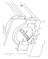
図3は実施例1のトナーディスペンサー装置の要部斜視説明図である。
図4は実施例1のトナーディスペンサー装置の要部斜視説明図であり、図3の状態から傾斜ホルダが引き出された引き出し位置に移動した状態の説明図である。
図5は実施例1のトナーディスペンサー装置の要部斜視説明図であり、図4の状態から傾斜ホルダが傾斜位置に移動した状態の説明図である。
図6は実施例1のトナーディスペンサー装置の要部斜視説明図であり、図5の状態から前端カバーが前端開放位置に移動した状態の説明図である。
図7は実施例1のトナーディスペンサー装置の要部斜視説明図であり、図6の状態からトナーカートリッジが取り出された状態の説明図である。
なお、図4では、本体側シャッタは流出口閉塞位置に移動しているはずであるが、理解の容易のために、流出口開放位置に移動した状態で図示している。
FIG. 3 is a perspective view illustrating a main part of the toner dispenser device according to the first exemplary embodiment.
FIG. 4 is an explanatory perspective view of a main part of the toner dispenser device according to the first exemplary embodiment, and is an explanatory diagram illustrating a state in which the tilt holder is moved from the state illustrated in FIG. 3 to the pulled-out position.
FIG. 5 is an explanatory perspective view of a main part of the toner dispenser device according to the first exemplary embodiment, and is an explanatory diagram illustrating a state in which the tilt holder is moved to the tilt position from the state illustrated in FIG. 4.
FIG. 6 is an explanatory perspective view of a main part of the toner dispenser device according to the first exemplary embodiment. FIG. 6 is an explanatory view showing a state where the front end cover is moved from the state shown in FIG.
FIG. 7 is an explanatory perspective view of a main part of the toner dispenser device according to the first exemplary embodiment, and is an explanatory view showing a state where the toner cartridge is taken out from the state shown in FIG.
In addition, in FIG. 4, although the main body side shutter should have moved to the outflow port obstruction | occlusion position, in order to understand easily, it has illustrated in the state which moved to the outflow port open position.
図1、図3〜図7において、K色のカートリッジホルダKHkは、画像形成装置本体U3に固定支持された引き出し支持部材の一例であって前端枠体の一例としての前側フレーム1と、リザーブタンクRTkの後端部に配置された固定部材の一例としてのホルダベース2を有する。図3〜図7において、前記前側フレーム1には、着脱されるトナーカートリッジKkが通過する円孔状の開口1aが形成されている。図3、図5〜図7において、前側フレーム1の下部には前方に突出するフレーム下部1bが形成されており、フレーム下部1bの上面には、開口1aに対応する下方に弧状に凹んだ挿入面1cが形成されている。挿入面1cには、許容移動部材の一例として、左端部に前方から後方に延びるロック解除溝1dが形成されている。回転ロック解除溝1dの右側には、規制解除部の一例として、前方から後方に行くに連れて上方に傾斜する傾斜面1eが形成されている。
図4〜図7において、ホルダベース2は、後端部に配置された板状の後端壁2aと、後端壁2aから前方に延びる半円筒状の筒壁2bとを有する。
1 and 3 to 7, the K cartridge holder KHk is an example of a drawer support member fixedly supported by the image forming apparatus main body U <b> 3 and a
4-7, the
図8は実施例1のホルダベースの要部説明図である。
図4〜図8において、前記後端壁2aには、本体側の誤装着防止部の一例として、円弧状の溝により構成されたハードキー装着溝2cが形成されており、トナーカートリッジKkの後端から後方に突出する着脱体側の誤装着防止部の一例としてのハードキーKk8が嵌ることが可能な構成となっている。したがって、現像器Gg〜Gkの色に対応する現像剤が収容されたトナーカートリッジKg〜Kkが装着された場合は、ハードキー装着溝2cとハードキーKk8との位置が一致して嵌るが、色が一致しない場合は位置がずれて嵌らないように予め設定されている。
FIG. 8 is an explanatory diagram of a main part of the holder base according to the first embodiment.
4 to 8, the
図9は流入口部分の説明図であり、図9Aはトナーカートリッジが装着位置に移動した状態の説明図、図9Bはトナーカートリッジが取り外された状態の説明図である。
図4〜図9において、後端壁2aには、駆動源2dからの駆動が伝達される駆動伝達部材の一例としてのカップリング3が支持されている。前記カップリング3は、装着されるトナーカートリッジKkの後端の被駆動伝達部材の一例としての図5に示すカップリングCPと噛み合う。図9において、実施例1の本体側のカップリング3は、トナーカートリッジKkのカップリングCPと確実に噛み合わせるために、付勢部材の一例としてのカップリングバネ3aにより前方に付勢されており、カップリング3は図示しない抜け止めにより抜け止めされた状態で、図9A、図9Bに示すように、前後方向に移動可能に支持されている。
FIG. 9 is an explanatory view of the inlet portion, FIG. 9A is an explanatory view of the state where the toner cartridge is moved to the mounting position, and FIG. 9B is an explanatory view of the state where the toner cartridge is removed.
4 to 9, a
図10は実施例1のホルダベースおよびトナーカートリッジの断面説明図であり、図10Aはトナーカートリッジが着脱可能位置に移動した状態の説明図、図10Bは本体シャッタ先端の要部説明図、図10Cはトナーカートリッジが装着位置に移動した状態の説明図である。
図3〜図8において、前記ホルダベース2の筒壁2bは、底部から左側に延びる弧状の内周面4と、内周面4の右部に形成され且つ内周面4よりも凹んだ形状に形成され、前後方向に延びる開閉部材通過路の一例としてのシャッタ通過溝6とを有する。図9、図10において、前記内周面4の後端部には、弧状内周面4よりも凹み且つシャッタ通過溝6よりも凸に形成され、筒壁2bの周方向に沿って延びる流入口形成部7が形成されており、流入口形成部7とシャッタ通過溝6との境界の段差部分により開閉部材押さえ部の一例としてのシャッタ押さえ部8が形成されている。
図8、図10Bにおいて、シャッタ押さえ部8の下方のシャッタ通過溝6には、落下現像剤収容部の一例として、前後方向に延び且つ下方に凹んだ凹部状に形成され、こぼれた現像剤を収容可能な現像剤ポケット6aが形成されている。
10A and 10B are cross-sectional explanatory views of the holder base and the toner cartridge according to the first exemplary embodiment. FIG. 10A is an explanatory view showing a state where the toner cartridge is moved to a detachable position. FIG. FIG. 4 is an explanatory diagram of a state in which the toner cartridge has moved to a mounting position.
3 to 8, the
8 and 10B, in the
図4、図9、図10において、前記流入口形成部7には、下方のリザーブタンクRTkに接続される通過口の一例としての流入口9が形成されている。前記流入口9の前後両側には、筒壁2bの内周面4に沿って円弧状に形成された遮蔽部材案内部の一例としての本体側シャッタガイド11が形成されており、本体側シャッタガイド11には、開閉部材の一例として、筒壁2bの内周面に沿った円弧状の本体側シャッタ12が周方向に移動可能に支持されている。
4, 9, and 10, the inflow
図11は実施例1の本体側シャッタの説明図である。
図8〜図11において、実施例1の本体側シャッタ12は、円弧状の板体により構成された開閉部材本体の一例としてのシャッタ本体12aを有する。シャッタ本体12aの左右方向中央部には、後方に延びる板状の後方連結部12bが形成されており、後方連結部12bには、上方に折れ曲がった形状に形成されて後端壁2aに対面する回転連動部の一例としてのハードキー連動部12cが形成されている。ハードキー連動部12cには、ハードキー装着溝2cに対応する位置に形成され且つトナーカートリッジKkのハードキーKk8が貫通可能な貫通口12dが形成されている。したがって、ハードキーKk8が貫通口12dに貫通した状態で、トナーカートリッジKkが回転すると、本体側シャッタ12が連動して移動する。よって、本体側シャッタ12は、閉塞位置の一例としての図10Aに示す流入口9を閉塞する流出口閉塞位置と、開放位置の一例としての図10Cに示す流入口9を開放する流出口開放位置との間で移動する。したがって、ハードキーKk8が貫通口12dに貫通した状態で、トナーカートリッジKkが回転すると、本体側シャッタ12が連動して移動する。よって、本体側シャッタ12は、閉塞位置の一例としての図10Aに示す流入口9を閉塞する流出口閉塞位置と、開放位置の一例としての図10Bに示す流入口9を開放する流出口開放位置との間で移動する。
FIG. 11 is an explanatory diagram of the main body side shutter according to the first embodiment.
8 to 11, the main
シャッタ本体12aの右端には、着脱対向部の一例として、シャッタ本体12aよりも厚い対向部12eが形成されている。また、シャッタ本体12aの下面には、シャッタ本体12aに沿って延びる円弧状の擦り切り抑制部の一例としての上げ底部12fが形成されており、上げ底部12fの前後両端部には、突出部の一例としてのリブ12hが前後一対形成されている。したがって、上げ底部12fと前後一対のリブ12hに囲まれた空間により、擦り切り抑制空間12gが形成されている。
図9において、実施例1の上げ底部12fの前後方向の幅は、流入口9よりも幅広に形成されており、リブ12hの下端が流入口9の縁よりも外側で流入口形成部7に接触するように形成されている。したがって、リブ12hは、現像剤が流出する幅である流出口Kk3の前後方向の端よりも外側において、流入口形成部7の上面に接触するように設定されている。
また、実施例1の上げ底部12fの左右方向の幅は、シャッタ押さえ部8から流入口9の右縁までの距離よりも短く形成されている。
At the right end of the shutter
In FIG. 9, the width in the front-rear direction of the raised
Further, the width in the left-right direction of the raised
したがって、前記本体側シャッタ12は、後方連結部12bが後端壁2aに支持された停止部材の一例としてのストッパ13に接触して停止され且つ流入口9が開放される図9A、図10Cに示す流入口9の開放位置と、流入口9が閉塞される図9B、図10Aに示す流入口9の閉塞位置との間を移動可能に支持されている。
図10Bにおいて、実施例1の本体側シャッタ12では、流入口9の閉塞位置において、対向部12eの位置が、シャッタ押さえ部8よりも手前側となり、トナーカートリッジKkとの間に、微小な空間が形成されるように設定されており、シャッタ12の右端面で押された現像剤がシャッタ通過溝6側に押されてこぼれることが低減されるように設定されている。
また、図10Bにおいて、実施例1の本体側シャッタ12では、上げ底部12fの左右方向の幅がシャッタ押さえ部8から流入口9の右縁までの距離よりも短く形成されており、本体側シャッタ12が閉塞位置に移動した状態では、シャッタ本体12aの下面が流入口9を閉塞する。
Therefore, the main
In FIG. 10B, in the main
10B, in the main
図9、図10において、流入口9の下方には、現像剤貯留部材の一例としてのリザーブタンクRTkが配置されている。リザーブタンクRTk内には、搬送部材の一例として、流入口9から流入した現像剤を前方または後方に搬送して、リザーブタンクRTk内で現像剤を循環させる左右一対の撹拌搬送部材RT1と、撹拌搬送部材RT1の左右方向中央部に形成されて、リザーブタンクRTk内を循環する現像剤を現像器Gkに搬送する補給搬送部材RT2とが配置されている。
9 and 10, a reserve tank RTk as an example of a developer storage member is disposed below the
(トナーカートリッジの説明)
図9、図10において、実施例1のホルダベース2に装着されるトナーカートリッジKkは、現像剤の収容部の一例として円筒状の容器本体Kk1を有する。容器本体Kk1の後端部には、容器本体Kk1の径方向外方に突出する流出口部Kk2が形成されている。流出口部Kk2には、容器本体Kk1の内部の現像剤が流出する通過口の一例としての流出口Kk3が形成されている。また、流出口部Kk2には容器本体Kk1の周方向に沿って移動可能な開閉部材の一例としてのカートリッジシャッタKk4が装着されており、カートリッジシャッタKkの流出口Kk3に対向する内面には、漏出防止部材の一例としてのカートリッジシールKk4aが支持されている。そして、ホルダベース2のシャッタ通過溝6の凹みの深さは、流出口Kk3を塞いだ状態のカートリッジシャッタKk4が通過可能な深さに形成されている。また、前記流入口形成部7の凹みの深さは、カートリッジシャッタKk4の厚みより浅く、且つ、流出口部Kk2の容器本体Kk1からの突出量よりも深く形成されている。
(Description of toner cartridge)
9 and 10, the toner cartridge Kk attached to the
したがって、図5〜図7、図10Aに示す流出口閉塞位置に示すように、トナーカートリッジKkが挿入されると、カートリッジシャッタKk4はシャッタ通過溝6を通過して後端まで装着可能である。なお、トナーカートリッジKkのカートリッジシャッタKk4の位置がシャッタ通過溝6に対応しない回転位置で挿入された場合、カートリッジシャッタKk4がホルダベース2の前端面と干渉して後端まで挿入不能となる。
トナーカートリッジKkが後端まで装着されると、ハードキー装着溝2cおよびハードキー連動部12cの貫通口12dを、トナーカートリッジKkの後端から突出するハードキーKk8が貫通する。なお、色の異なるトナーカートリッジKy,Km,Kc,Ko,Kgを挿入した場合、ハードキーKk8の位置が一致せず、後端まで挿入されず、誤装着が防止される。
Therefore, as shown in the outlet closing position shown in FIGS. 5 to 7 and FIG. 10A, when the toner cartridge Kk is inserted, the cartridge shutter Kk4 can pass through the
When the toner cartridge Kk is mounted to the rear end, the hard key Kk8 protruding from the rear end of the toner cartridge Kk passes through the hard
そして、トナーカートリッジKkが後端まで装着された状態で、トナーカートリッジKk前端に設けられた操作部の一例としてのカートリッジハンドルKk6を利用者が回転させると、カートリッジシャッタKk4がシャッタ押さえ部8で引っ掛かって回転せず、且つ、容器本体Kk1および流出口部Kk2が回転する。このとき、ハードキーKk8の回転に伴ってハードキーKk8が貫通する貫通口12dを介して、本体側シャッタ12も連動して回転し、本体側シャッタ12が移動する。よって、流出口Kk3が開放されると共に、流入口9も開放され、図3B、図9A、図10Cに示す流出口開放位置に示すように、流出口Kk3と流入口9とが接続される。
When the user rotates the cartridge handle Kk6 as an example of the operation unit provided at the front end of the toner cartridge Kk with the toner cartridge Kk mounted to the rear end, the cartridge shutter Kk4 is hooked by the
そして、駆動源2dから本体側のカップリング3に駆動が伝達されると、本体側のカップリング3と噛み合うトナーカートリッジKkのカップリングCPに駆動が伝達される。したがって、容器本体Kk1内に配置され且つカップリングCPに連結された現像剤搬送部材の一例としてのアジテータCP1が回転して、容器本体Kk1内の現像剤を流出口Kk3に向けて搬送し、流出口Kk3から現像剤が供給される。
When driving is transmitted from the driving
なお、図9Bにおいて、実施例1では、トナーカートリッジKkが装着された状態では、カップリング3のカップリングバネ3aの弾性力が作用しており、トナーカートリッジKkは前方に付勢され、流出口部Kk2の前端が、シャッタガイド11の前端に接触した状態で保持される。実施例1では、図9Bに示す流出口部Kk2の前端が、シャッタガイド11の前端に接触した状態において、流出口Kk3の前後方向の幅が、流入口9の前後方向の幅の内側に配置されるように設定されている。
なお、図4において、実施例1のトナーカートリッジKkの前端部には、被規制部の一例として、容器本体Kk1の径方向に突出する回転規制片Kk7が設けられている。
In FIG. 9B, in Example 1, in the state where the toner cartridge Kk is mounted, the elastic force of the
In FIG. 4, the front end portion of the toner cartridge Kk according to the first exemplary embodiment is provided with a rotation regulating piece Kk7 that protrudes in the radial direction of the container body Kk1 as an example of the regulated portion.
(引き出し体の説明)
図12は実施例1の引き出し体部分の要部説明図であり、図12Aは図4の矢印XIIA方向から見た要部説明図、図12Bは図6のXIIB−XIIB線断面図である。
図13は図5の矢印XIII方向から見た要部説明図である。
なお、図12、図13および以降の図面において、装置の説明及び理解の容易のために、外側からは見えない内部に配置された部材を実線で表示して、外側に配置された部材を破線や鎖線で示したり図示を省略したりしている。
(Description of drawer)
12 is an explanatory view of the main part of the drawer body portion of Example 1, FIG. 12A is an explanatory view of the main part viewed from the direction of arrow XIIA in FIG. 4, and FIG. 12B is a sectional view taken along the line XIIB-XIIB in FIG.
FIG. 13 is an explanatory view of a main part viewed from the direction of arrow XIII in FIG.
In FIG. 12, FIG. 13 and the subsequent drawings, for ease of explanation and understanding of the apparatus, members arranged inside that are not visible from the outside are indicated by solid lines, and members arranged outside are indicated by broken lines. It is indicated by a chain line or is not shown.
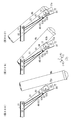
図3〜図7において、前記ホルダベース2の左右両側には、引き出し案内部材の一例として、前後方向に延びる左右一対のガイドレール16が固定支持されている。図12A、図13において、前記ガイドレール16は、重力方向下側に配置された案内部材本体の一例としてのレール本体17を有する。前記レール本体17は、上下方向に延びる側壁部17aと、側壁部17aの上端から内側に折れ曲がった形状に形成された下側案内部17bとを有する。
前記下側案内部17bの上面には、下側コロ案内面17cが形成されている。前記レール本体17の外側面には、上方に延びる上側案内部材の一例としての上側ガイドレール18が螺子19により固定支持されている。前記上側ガイドレール18は、上方に延びる閉塞部の一例としての外側カバー部18aと、外側カバー部18aの上端から内側に折曲げられた形状の上側案内部18bとを有する。前記上側案内部18bの下面には上側コロ案内面18cが形成されている。
3 to 7, a pair of left and right guide rails 16 extending in the front-rear direction are fixedly supported on the left and right sides of the
A lower
左右一対のガイドレール16の内側には、引き出し体の一例としての左右一対の被ガイドレール21,22が前後方向に移動可能に支持されている。図3、図12A、図13において、前記被ガイドレール21,22は、上下方向に延びる引き出し体本体21a,22aと、引き出し体本体21a,22aの上下両端から外側に折れ曲がった形状に形成された上側被案内部21b,22bおよび下側被案内部21c,22cとを有する。前記上側被案内部21b,22bは、下面が上側案内部18bの上面に対向して配置され、被ガイドレール21,22が、引き出し方向である前方向と、押入方向である後方向に移動可能に支持されている。
Inside the pair of left and right guide rails 16, a pair of left and right guided rails 21 and 22 as an example of a drawer body are supported so as to be movable in the front-rear direction. 3, FIG. 12A and FIG. 13, the guided
前記引き出し体本体21a,22aの後部には、前後一対の被案内部材の一例としてのコロ23が回転可能に支持されており、前記コロ23は、ガイドレール16の下側コロ案内面17cおよび上側コロ案内面18cに挟まれた状態で配置されている。したがって、被ガイドレール21,22が移動する際に、コロ23が各コロ案内面17c,18c上を回転することで、コロ23が設けられていない場合に比べて、摩擦抵抗等が少なく、弱い力で円滑に前後方向に移動可能となっている。
A
図3において、前記引き出し体本体21a,22aの後部には、外方であるガイドレール16の側壁部17a側に突出する引き出し被停止部の一例としてのストッパ24が形成されている。なお、図3において、図面の関係上、左側の被ガイドレール21のストッパ24のみ図示している。図12Bにおいて、前記ストッパ24は、前記レール本体17と上側ガイドレール18とを固定し且つ貫通して配置された引き出し停止部の一例としての前記螺子19の内端に接触、離間可能に配置されている。したがって、被ガイドレール21,22が前方に引き出されて、図4に示す引き出し位置まで引き出されると、ストッパ24と螺子19とが接触して、被ガイドレール21,22のそれ以上の前方への移動が規制される。よって、実施例1の被ガイドレール21,22は、図3に示す収容位置と、図4に示す引き出し位置との間を移動可能に支持されている。
In FIG. 3, a
図12、図13において、右側の被ガイドレール22の引き出し体本体22aの前端部には、左右方向に貫通する貫通孔26が形成されている。
前記右側の被ガイドレール22には、貫通孔26の後方の外側面に沿って、前後方向に延びる連動部材の一例としてのリンク27がリンク回転中心27aを中心として回転可能に支持されている。前記リンク27の後端には、右側のガイドレール16の前端の誤挿入停止部16aに接触、離間可能なJ字形状に折曲げられた被停止部27bが形成されている。したがって、前記リンク27は、被停止部27bが誤挿入停止部16aから離間して被ガイドレール22が収容位置と引き出し位置との間を移動可能な図12に示す停止部離間位置と、被停止部27bが誤挿入停止部16aに接触して被ガイドレール22が引き出し位置から収容位置への移動が規制される図13に示す停止部接触位置と、の間でリンク回転中心27aを中心として回転可能に支持されている。
前記リンク27の前端には、貫通孔26に対応して形成され且つ前後方向に延びる長孔状の連結孔27cが形成されている。
12 and 13, a through
A
At the front end of the
(傾斜ホルダの説明)
図14は実施例1の制動部材の説明図である。
なお、図14において、ホルダフレームの理解を容易にするために、ホルダカバーは図示が省略されている。
図3〜図13において、前記被ガイドレール21,22の前端部には、保持体の一例であって回転保持体の一例としての傾斜ホルダ31がホルダ回転軸32,33を中心として回転可能に支持されている。前記傾斜ホルダ31は、枠体の一例としてのホルダフレーム36を有する。図14において、ホルダフレーム36は、トナーカートリッジKkの軸方向に沿って延びる板状のホルダフレーム底壁36aと、ホルダフレーム底壁36aの左右両側端から上方に延びるホルダフレーム左側壁36bおよびホルダフレーム右側壁36cと、を有する。前記ホルダフレーム左側壁36bおよびホルダフレーム右側壁36cの後端部には、前記ホルダ回転軸32,33が連結されている。
(Description of tilt holder)
FIG. 14 is an explanatory diagram of the braking member of the first embodiment.
In FIG. 14, the holder cover is not shown for easy understanding of the holder frame.
3 to 13, an
図12、図13において、前記ホルダフレーム右側壁36cには、右側のホルダ回転軸33から後方に離れた位置に、右方に延びる連結体の一例としてのリンク連結ピン36dが支持されている。前記リンク連結ピン36dは、被ガイドレール22の貫通孔26を貫通し、リンク27の連結孔27cに連結されている。実施例1の連結孔27cは、長孔状に形成されており、リンク連結ピン36dは連結孔27cに沿って移動可能な状態で連結されている。図12、図13に示すように、リンク連結ピン36dは、ホルダ回転軸33に対して近傍で離れた位置に配置されている。
したがって、傾斜ホルダ31がホルダ回転軸32,33を中心として回転すると、リンク連結ピン36dにより連結されたリンク27が連動して、図12に示す停止部離間位置と、図13に示す停止部接触位置との間で回転移動する。
12 and 13, a
Therefore, when the
図14において、左側のホルダ回転軸32には、制動部材の一例であって過負荷保護装置の一例としてのワンウェイヒンジ38が組み込まれている。前記ワンウェイヒンジ38は、予め設定された設定回転力以上の回転力が作用した場合に回転力の伝達を遮断する過負荷保護装置、いわゆるトルクリミッタの機能と、一方向の回転のみ伝達し且つ他方向の回転に対して空回転させる一方向回転遮断装置、いわゆるワンウェイクラッチの機能と、を有する市販の装置である。そして、実施例1のワンウェイヒンジ38は、ホルダ回転軸32を中心として特定の回転方向に作用する回転力が、予め設定された設定回転力以上の場合に、設定回転力以上の回転力の伝達を遮断すると共に、前記特定の回転方向とは逆方向の回転力が作用した場合は回転力の伝達を遮断せずに、回転力を伝達させる。すなわち、図4に示す挿入可能位置から図5に示す着脱位置の一例としての傾斜位置に向かう回転方向である傾斜回転方向の回転力が前記設定回転力以上の場合に回転力の伝達が遮断されて、傾斜位置に回転移動する移動速度が抑制されると共に、前記傾斜位置から前記挿入可能位置に向かう回転方向である復帰回転方向の回転力を伝達させるように設定されている。そして、実施例1では、前記設定回転力は、重力によって作用する傾斜ホルダ31を回転させる自然回転力よりも小さな値に設定されている。
In FIG. 14, a one-
図15は実施例1の傾斜ホルダの要部説明図であり、図15Aは図4の挿入可能位置に移動した状態の傾斜ホルダ前部の要部説明図、図15Bは図15AのXVB−XVB線断面図である。
図16は実施例1の傾斜ホルダの要部説明図であり、図7の傾斜位置に移動した状態の傾斜ホルダ前部の説明図である。
図15、図16において、ホルダフレーム36の前部において、ホルダフレーム底壁36aには切り起こされた形状の切り起こし部39が左右一対形成されている。なお、図面の関係上、図15、図16には右側の切り起こし部39のみ図示している。
15 is an explanatory view of a main part of the tilt holder according to the first embodiment, FIG. 15A is an explanatory diagram of a main part of the front part of the tilt holder in a state where it is moved to the insertable position in FIG. 4, and FIG. 15B is XVB-XVB in FIG. It is line sectional drawing.
FIG. 16 is an explanatory diagram of a main part of the tilt holder according to the first embodiment, and is an explanatory diagram of the front part of the tilt holder in a state of being moved to the tilt position of FIG.
15 and 16, a pair of left and right cut-and-raised
図15、図16において、前記ホルダフレーム側壁36b,36cには、前記切り起こし部39に対向する位置に、左右方向に貫通する掛かり通過口の一例としてのピン通過口41が形成されている。前記切り起こし部39には、ピン通過口41を通過してホルダフレーム側壁36b,36cの外方に突出する掛かり部材の一例としてのピン42が左右方向に移動可能に支持されている。
図15Bにおいて、前記ピン42は、切り起こし部39の支持孔39aに貫通した状態で左右方向に移動可能に支持される被支持部42aを有する。前記被支持部42aの外側には、ピン通過口41を貫通し且つ被支持部42aよりも大径のピン本体42bが一体的に形成されている。ピン本体42bの外端部には、ピン本体42bよりも大径の円板状のバネ支持部42cが一体形成されている。バネ支持部42cには、バネ支持部42cから外方に突出する突起状の掛かり部42dが形成されている。
15 and 16, the holder
In FIG. 15B, the
図15、図16において、前記切り起こし部39と、バネ支持部42cとの間には、バネ支持部42cを外方に付勢する付勢部材の一例としてのピン付勢バネ43が装着されている。
また、前記ホルダフレーム側壁36b,36cの前記切り起こし部39よりもさらに前方には、回転規制部の一例として、各ホルダフレーム側壁36b,36cから外方に延びる左右一対のサポート連結スタッド44が支持されている。
15 and 16, a
Further, a pair of left and right
図17は被ガイドレールが引き出し位置に移動し且つ傾斜ホルダが挿入可能位置に保持された状態のサポートの要部説明図である。
図18は図17に示す状態から傾斜ホルダが傾斜位置に移動し且つ前端カバーが開放位置に移動した状態のサポートの要部説明図である。
図12〜図18において、前記ホルダフレーム36の各ホルダフレーム側壁36b,36cの外側には、補助回転体の一例として、前後方向に延びる板状の左側サポート46および右側サポート47が配置されている。前記サポート46,47の後端部は、ホルダ回転軸32,33の前側に離れた位置に配置された補助回転軸の一例としてのサポート回転軸48により、被ガイドレール21,22に回転可能に支持されている。図12〜図14に示すように、実施例1のサポート回転軸48は、ホルダ回転軸32,33に対して前側近傍に離れた位置、すなわち、近接して配置されている。
FIG. 17 is an explanatory view of the main part of the support in a state where the guided rail is moved to the pulling position and the tilt holder is held at the insertion position.
FIG. 18 is an explanatory view of a main part of the support in a state where the tilt holder is moved to the tilt position and the front end cover is moved to the open position from the state shown in FIG.
12 to 18, a plate-like
図12〜図18において、各サポート46,47の前後方向中央部には、傾斜ホルダ31が図17に示す挿入可能位置に移動した状態における前記掛かり部42dに対応して、被掛かり部の一例としてのラッチ孔51が形成されている。すなわち、前記ラッチ孔51は、傾斜ホルダ31が図17に示す挿入可能位置に移動した状態では、図15Bに示すように、ピン付勢バネ43の弾性力により掛かり部42dがラッチ孔51に掛かった状態、すなわち、嵌った状態で保持される。一方、傾斜ホルダ31が図18に示す傾斜位置に移動した状態では、ホルダフレーム36のホルダ回転軸32,33と、サポート回転軸48がずれており、掛かり部42dの位置とラッチ孔51の位置との間にずれが発生するため、掛かり部42dがピン付勢バネ43の弾性力に抗して内側に移動し、ラッチ孔51から離間した状態、すなわち、抜けた状態となるように構成されている。
12-18, in the center part in the front-rear direction of each
図15〜図18において、各サポート46,47の前部には、前記サポート連結スタッド44に対応して、傾斜停止溝52が形成されている。図15、図17において、前記傾斜停止溝52は、サポート46,47に沿って延びる案内溝部53と、案内溝部53の前端から上方に延びる回転規制溝部54と、を有し、サポート連結スタッド44が溝に沿って移動可能な幅の略L字状の溝により形成されている。図15〜図18において、前記案内溝部53の後端には、図17に示す挿入可能位置において前記サポート連結スタッド44に接触して、挿入可能位置よりも上方への傾斜ホルダ31の回転を規制する上回転規制部の一例としての上回転ロック面53aが形成されている。
In FIGS. 15 to 18, inclined stop
また、前記案内溝部53の前端には、図18に示す傾斜位置において前記サポート連結スタッド44に接触して、傾斜位置よりも下方への傾斜ホルダ31の回転を規制する下回転規制部の一例としての下回転ロック面53bが形成されている。すなわち、サポート連結スタッド44と下回転ロック面53bが接触する傾斜ホルダ31の回転位置が傾斜位置に設定されており、サポート連結スタッド44と下回転ロック面53bとの接触により傾斜ホルダ31が傾斜位置に保持される。
さらに、下回転ロック面53bから上方に離れた位置である前記回転規制溝部54の内周面により、開放回転規制部の一例としての回転ロック面54aが構成されている。
Further, at the front end of the
Furthermore, a
図19は実施例1の傾斜ホルダの前端部の要部説明図であり、傾斜ホルダが挿入可能位置に移動した状態の説明図である。
図20は実施例1の傾斜ホルダの前端部の要部説明図であり、傾斜ホルダが傾斜位置に移動した状態の説明図である。
図21は実施例1の傾斜ホルダの前端部の要部説明図であり、図20に示す状態から前端カバーが前端開放位置に向けて回転を開始した状態の説明図である。
図22は実施例1の傾斜ホルダの前端部の要部説明図であり、図21に示す状態から前端カバーが前端開放位置に移動した状態の説明図である。
図17〜図22において、各サポート46,47の前端には、回転被連動部の一例として、サポート46,47を左右方向に貫通するロック開口56が形成されている。
FIG. 19 is an explanatory diagram of a main part of the front end portion of the tilt holder according to the first embodiment, and is a diagram illustrating a state in which the tilt holder is moved to an insertable position.
FIG. 20 is an explanatory diagram of a main part of the front end portion of the tilt holder according to the first embodiment, and is a diagram illustrating a state in which the tilt holder is moved to the tilt position.
FIG. 21 is an explanatory diagram of a main part of the front end portion of the tilt holder according to the first embodiment, and is an explanatory diagram showing a state in which the front end cover starts rotating from the state shown in FIG. 20 toward the front end open position.
FIG. 22 is an explanatory view of a main part of the front end portion of the tilt holder according to the first embodiment, and is an explanatory view showing a state where the front end cover is moved from the state shown in FIG.
17 to 22, a
図19において、前記ロック開口56は、後端側から下に凸の弧状に延びる案内部の一例としてのカバースタッドガイド溝56aと、カバースタッドガイド溝56aの前端部に連続して形成され且つ前方に行くに連れて下方に傾斜した後、重力方向下方に延びる内側面を有する回転規制解除部の一例としてのサポートロック解除部56bと、サポートロック解除部56bに一体的に形成され且つサポートロック解除部56bの下面に対して下方に凹んだ形状の開閉移動規制部の一例としてのカバーロック部56cと、を有する。
In FIG. 19, the
図23は実施例1の傾斜ホルダおよび前端カバーの要部説明図であり、図6に対応するトナーカートリッジが装着された状態の説明図である。
図7、図15〜図18において、前記ホルダフレーム36には、保持体被覆部材の一例としてのホルダカバー61が固定支持されている。前記ホルダカバー61は、ホルダフレーム36の底壁36aの前側および左右両側に配置された上側被覆部の一例としての上側カバー62を有する。前記上側カバー62は、半円筒状の上面である着脱体保持面の一例としてのカートリッジ保持面62aを有する。
FIG. 23 is an explanatory diagram of main parts of the tilt holder and the front end cover of Example 1, and is an explanatory diagram of a state in which the toner cartridge corresponding to FIG. 6 is mounted.
7 and 15 to 18, a
図16、図23において、前記上側カバー62の前端には、前端支持部の一例としての前端壁63が一体的に形成されている。前端壁63には、装着されるトナーカートリッジKkの外径よりも小径の半円弧状の開口63aが形成されており、開口63aの左下部にはトナーカートリッジKkと略同径の回転規制装着部63a1が形成されている。したがって、前端壁63は、装着されるトナーカートリッジKkの幅方向の両端に対して、両側から内側に張り出した形状に形成されている。したがって、トナーカートリッジKkが装着された場合に、トナーカートリッジKkの前端面を前端壁63が支持可能に構成されている。したがって、前端壁63の上端の角部には、前端案内部の一例として、トナーカートリッジKkの外径よりも幅が狭い間隔で配置された左右一対のガイド角部63bが形成されている。
16 and 23, a
図24は実施例1の傾斜ホルダの前カバーが前端閉塞位置に移動した状態の要部説明図である。
図25は実施例1の回転規制機構の要部説明図である。
図26は実施例1の回転規制機構の分解説明図であり、図26Aは分解図、図26Bは図26Aの矢印XXVIB方向から見た図である。
図16、図23〜図25において、前端壁63の下端には、前端壁63に対して後方に凹み且つ下方に延びる形状に形成され、回転規制片Kk7が接触可能なリブ接触部63cが形成されている。
図26Aにおいて、前端壁63の回転規制装着部63a1の後面側には、付勢装着部の一例として、後方に突出するバネ装着突起63dが形成されている。前記バネ装着突起63dの近傍には、腕部支持体の一例として、後方に突出するアーム引っ掛け突起63eが形成されている。
FIG. 24 is an explanatory diagram of a main part in a state where the front cover of the tilt holder according to the first embodiment is moved to the front end closing position.
FIG. 25 is an explanatory diagram of a main part of the rotation restricting mechanism of the first embodiment.
FIG. 26 is an exploded explanatory view of the rotation restricting mechanism of the first embodiment, FIG. 26A is an exploded view, and FIG. 26B is a view seen from the direction of arrow XXVIB in FIG.
16 and 23 to 25, a
In FIG. 26A, on the rear surface side of the rotation restricting mounting portion 63a1 of the
図3〜図7、図15、図16、図23、図24において、前記上側カバー62の左上端縁には、前記左側壁36bおよび左側サポート46の外側を被覆する左カバー64が上側カバー62に一体的に形成されている。前記左カバー64の後端部には、左側サポート46およびワンウェイヒンジ38が外部に露出することを防止し、且つ、左側壁36bと左側の被ガイドレール21との隙間を埋めるように、前後方向中央部よりも左右方向の幅が広く形成された後端保護部64aが形成されている。
図3〜図7、図15、図16、図23、図25において、前記上側カバー62の右上端縁には、前記右側壁36cおよび右側サポート47の外側を被覆する右カバー66が上側カバー62に一体的に形成されている。
前記ホルダフレーム36およびホルダカバー61により、トナーカートリッジKkを保持する保持体本体36+61が構成されている。
3 to 7, 15, 16, 23, and 24, a
In FIGS. 3 to 7, 15, 16, 23, and 25, a
The
(回転規制機構の説明)
図27は図25の矢印XXVII方向から見た図であり、図27Aは回転規制部材が規制位置に移動し且つ移動規制位置に移動した状態の説明図、図27Bは回転規制部材が規制位置且つ移動規制解除位置に移動した状態の説明図、図27Cは回転規制部材が許容位置に移動した状態の説明図である。
図26、図27において、前記リブ接触部63cの左端には、移動規制部材の一例として、後方に延びる板状のロック部67が形成されている。前記ロック部67には、規制係合部の一例として、開口により構成されたロック口67aが形成されている。実施例1のロック口67aは、前端部の前後方向に延びる許容係合部67bと、許容係合部67bの後端に形成され且つ下方に段差状に下がった形状の許容規制部67cとを有する。
(Explanation of rotation regulation mechanism)
27 is a view as seen from the direction of arrow XXVII in FIG. 25. FIG. 27A is an explanatory diagram of a state in which the rotation restricting member has moved to the restricting position and moved to the restricting position, and FIG. FIG. 27C is an explanatory diagram of a state where the rotation restricting member has moved to an allowable position.
26 and 27, a plate-
図16、図23〜図26において、前端壁63の回転規制装着部63a1には、回転規制部材の一例としての回転ロック部材68が支持されている。図26A、図26Bにおいて、実施例1の回転ロック部材68は、前端壁63の開口63aに沿った形状を有するロック前壁68aを有する。ロック前壁68aの下端には、後方に延びる板状のロック底壁68bが一体的に形成されており、ロック底壁68bの右部上面により腕部支持体の一例としてアーム付勢面68b1が形成されている。
前記ロック底壁68bの後端には、上方に延びるロック後壁68cが形成されている。ロック後壁68cの左端には、付勢装着部の一例として、バネ装着突起63dに対応するバネ装着突起68dが形成されている。
16 and 23 to 26, a
A lock
図26B、図27において、ロック底壁68bの右端には、移動規制部の一例として、ロック口67aに対応して形成され且つロック口67aに掛かるロック爪68eが形成されている。
図26、図27において、ロック底壁68bの左部下面には、被移動部の一例として、下方に延びるスライド突起68fが形成されている。
In FIG. 26B and FIG. 27, a
26 and 27, a
図26Aにおいて、バネ装着突起63d,68dの間には、規制付勢部材の一例としてのコイルバネ69が装着されている。コイルバネ69は、圧縮バネにより構成されており、ロック部材68のバネ装着突起68dを後方に付勢する力を作用させる。また、実施例1のコイルバネ69は、前後両端に腕部の一例としてのアーム69a,69bが延びており、前側のアーム69aはアーム引っ掛け突起63eに支持される、そして、後側のアーム69bはロック部材68のアーム付勢面68b1に接触して、アーム付勢面68b1を下方に付勢する。すなわち、実施例1のコイルバネ69は、ロック部材68を後方に付勢する通常のコイルバネの機能と、ロック部材68のアーム付勢面68b1を下方に付勢するネジリバネの機能とを併せ持っている。
In FIG. 26A, a
したがって、実施例1のロック部材68は、コイルバネ69により後方に付勢され、且つ、アーム付勢面68b1が下方に付勢されている。すなわち、アーム付勢面68b1の下方への付勢に伴って、ロック部材68は、バネ装着突起63d,68dの部分を中心として、ロック部材68の右側が下方に回転する方向の力を受ける。したがって、図27において、ロック爪68eが後方且つ下方に移動する方向の力を受けており、ロック爪68eが図27Aに示すように、許容規制部67cに係合して、ロック部材68の前方への移動が規制される移動規制位置に保持される。
図25において、ロック部材68が移動規制位置に保持されると、ロック部材68のロック前壁68aが、前端壁63aの回転規制装着部63a1に接触した状態である規制位置に保持される。したがって、装着されたトナーカートリッジKkの回転規制片Kk7の左方に隣接した状態となり、トナーカートリッジKkが回転しようとしても、回転規制片Kk7と接触して、回転を規制する。
Therefore, the
In FIG. 25, when the
図28はトナーカートリッジが流出口開放位置に移動した状態の説明図である。
図3、図28において、傾斜ホルダ31にトナーカートリッジKkが収容された状態で、被ガイドレール21,22が収容位置に向かって移動する場合に、スライド突起68fがロック解除溝1dの後端面に接触する前に、ロック底壁68bの下面の右部が傾斜面1eに接触する。したがって、トナーカートリッジKkの挿入に伴って、ロック底壁68bの右部が、傾斜面1eに沿って上方に回転し、コイルバネ69のネジリバネ機能の付勢力に抗して、図27Bに示すように、ロック爪68eが移動規制位置から上方の移動規制解除位置に移動する。したがって、ロック爪68eと許容規制部67cとの係合が解除され、ロック部材68が前方に移動可能な状態となる。
FIG. 28 is an explanatory diagram of a state where the toner cartridge has moved to the outlet opening position.
3 and 28, when the guided
そして、図3、図28において、トナーカートリッジKkが収容位置まで移動すると、スライド突起68fがロック解除溝1dの後端面に接触する。このとき、ロック爪68eと許容規制部67cとの係合が解除され、ロック部材68が前方に移動可能であるため、ロック部材68が前方に移動する。したがって、図27Cに示すように、ロック爪68eが許容係合部67bに係合し、図28に示すように、ロック部材68のロック前壁68aと回転規制装着部63a1との間に隙間が空いた状態となる許容位置に移動する。したがって、ロック部材68が許容位置に移動した状態では、トナーカートリッジKkの回転規制片Kk7にロック部材68のロック前壁68aが干渉せず、トナーカートリッジKkの回転が許容される。
3 and 28, when the toner cartridge Kk moves to the accommodation position, the
(前カバーの説明)
図3〜図7、図15〜図24において、前記ホルダカバー61の前端部には、前端開閉部材の一例としての前カバー71が支持されている。図19〜図24において、前記前カバー71は、半円筒状の前カバー筒壁72と、前記前カバー筒壁72の左右両端から前記左カバー64および右カバー66に沿って延びる前カバー左壁73および前カバー右壁74と、前記前端壁63に対応して前カバー筒壁72の前端に形成された前カバー前壁76と、を有する。
(Description of front cover)
3 to 7 and 15 to 24, a
前記前カバー左壁73および前カバー右壁74には、左右方向内側に延び且つ左カバー64および右カバー66に回転可能に支持されるカバー回転軸77を有する。したがって、実施例1の前カバー71は、カバー回転軸77を中心として、図6、図7、図15、図17、図19、図20、図24に示す前端閉塞位置と、図5、図16、図18、図22、図23に示す前端開放位置との間で回転可能に支持されている。
図16、図23において、前端開放位置に移動した状態における前カバー筒壁72の前側上端には、案内部の一例として、トナーカートリッジKkの外表面に沿った形状に形成された左右一対のカートリッジガイド部72aが形成されている。
The front cover left
16 and 23, a pair of left and right cartridges formed in a shape along the outer surface of the toner cartridge Kk, as an example of a guide portion, are provided at the front upper end of the front
また、前記前カバー左壁73および前カバー右壁74には、図17、図19等に示す前端閉塞位置においてカバー回転軸77の前側下方に離れた位置であり且つ前記サポート46,47のロック開口56に対応する位置に、左右方向内側に突出する回転連動部の一例としてのロックスタッド78が形成されている。前記ロックスタッド78は、ロック開口56に嵌まっており、前カバー71の回転時やサポート46,47の回転時にロック開口56内を移動可能な状態で連結されている。
Further, the front cover left
前記カバー前壁76には、前端壁63の開口63aに対応するトナーカートリッジKkの外径よりも小径の半円弧状の開口76aが形成されている。
したがって、ホルダカバー61の前端壁63および前カバー71の前壁76とにより、傾斜ホルダ31の傾斜時に、トナーカートリッジKkの前方への移動を規制して脱落を防止する引き出し規制部材63+76が構成されている。
The
Accordingly, the
(実施例1の作用)
前記構成を備えた本発明の実施例1の前記画像形成装置Uでは、画像形成動作、いわゆる、ジョブが実行されて、前記各現像器GG〜GKで現像剤が消費されると、消費量に応じて、トナーディスペンス装置U3aが作動して、各トナーカートリッジKg〜Kkから現像剤が補給される。トナーカートリッジKg〜Kk内の現像剤が空になると、トナーカートリッジKg〜Kkが交換される。
(Operation of Example 1)
In the image forming apparatus U of
(トナーカートリッジを取り外す作業の説明)
図3において、空になったトナーカートリッジKkを交換する場合、図3に示す収容位置において、トナーカートリッジKkのカートリッジハンドルKk6を操作して、図10Cに示す流出口開放位置から図10Aに示す流出口閉塞位置まで、トナーカートリッジKkを回転させる。トナーカートリッジKkの回転に伴って、カートリッジシャッタKk4および本体側シャッタ12が回転して、流出口Kk3および流入口9が閉塞される。
トナーカートリッジKkが流入口9からカートリッジKk4の位置まで移動する間に、
流出口Kk3が流入口形成部7の上面に対向した状態で通過し、このとき、流出口Kk3から現像剤が流入口形成部7の上面に付着することがある。
(Explanation for removing the toner cartridge)
In FIG. 3, when the emptied toner cartridge Kk is replaced, the cartridge handle Kk6 of the toner cartridge Kk is operated in the accommodation position shown in FIG. 3, and the flow shown in FIG. 10A from the outlet opening position shown in FIG. 10C. The toner cartridge Kk is rotated to the outlet closing position. As the toner cartridge Kk rotates, the cartridge shutter Kk4 and the main
While the toner cartridge Kk moves from the
The outlet Kk3 passes in a state of facing the upper surface of the
図29は従来のカートリッジシャッタの説明図である。
図29において、従来の本体側シャッタ01のように、上げ底部12fが形成されていない構成では、流入口形成部7に付着した現像剤を、本体側シャッタ01の右端が擦り切りながら右方に移動する。したがって、擦り切られた現像剤は、流入口形成部7の右端からシャッタ通過溝6にこぼれ、シャッタ通過溝6が汚染される。したがって、次に装着されるトナーカートリッジKkに、こぼれた現像剤が付着し、トナーカートリッジKkが交換される度に、トナーカートリッジKkに付着した現像剤が画像形成装置Uの外部に落下したり、利用者の手が汚れる恐れがある。
これに対して、実施例1の本体側シャッタ12では、上げ底部12fが、形成されており、本体側シャッタ12が流入口9の閉塞位置に移動する際に、流入口形成部7の上面との間に擦り切り抑制空間12gが空いた状態で移動しており、流入口形成部7の上面の現像剤が擦り切られることが抑制されている。したがって、現像剤がこぼれて画像形成装置Uの内外が汚染されることが抑制される。
FIG. 29 is an explanatory diagram of a conventional cartridge shutter.
In FIG. 29, in the configuration in which the raised
On the other hand, in the main
また、実施例1では、トナーカートリッジKkの流出口Kk3の位置は、流出口部Kk2の前端が、シャッタガイド11の前端に接触した状態において、流入口9の前後方向の幅の内側に配置されるように設定されており、トナーカートリッジKkを流出口閉塞位置側に移動する間に流出口Kk3が通過する軌跡が、擦り切り抑制空間12g内になるように設定されている。したがって、本体側シャッタ12が移動する際に、上げ底部12fの前後両側の縁であるリブ12hの部分で現像剤が擦り切られることが低減されている。
また、実施例1では、現像剤ポケット6aが形成されており、現像剤がこぼれても現像剤ポケット6aに収容され、画像形成装置Uの内外の汚染が低減されている。
さらに、実施例1では、流入口9の閉塞位置において、本体側シャッタ12の対向部12eの位置が、シャッタ押さえ部8よりも手前側となり、トナーカートリッジKkとの間に微小な空間が形成されており、シャッタ12の右端面で押された現像剤がシャッタ通過溝6側に押されてこぼれることが低減されており、画像形成装置Uの内外の汚染が低減されている。
In the first exemplary embodiment, the position of the outlet Kk3 of the toner cartridge Kk is disposed inside the width of the
In the first embodiment, the
Furthermore, in the first exemplary embodiment, the position of the facing
前記流出口閉塞位置にトナーカートリッジKkが回転すると、流出口部Kk2がシャッタ通過溝6に移動し、トナーカートリッジKkおよび被ガイドレール21,22、傾斜ホルダ31が前方に引き出し可能な状態となる。トナーカートリッジKkのカートリッジハンドルKk6を操作して収容位置から前方に引き出されると、図3に示す収容位置から図4に示す引き出し位置に向けて移動する際に、ロック部材68のスライド突起68fとロック解除溝1dとの接触が解除され、ロック底壁68bの下面と傾斜面1eとの接触が解除される。したがって、コイルバネ69の弾性力が作用して、ロック部材68のロック爪68eが許容係合部67bに係合する許容位置から、許容規制部67cに係合する移動規制位置に移動する。したがって、ロック部材68が回転規制片Kk7に干渉して、トナーカートリッジKkの回転が規制される、したがって、引き出し作業中にトナーカートリッジKkが回転してしまうことが低減され、操作性が向上している。
When the toner cartridge Kk rotates to the outlet closing position, the outlet Kk2 moves to the
図3、図4において、図3に示す収容位置から前方に引き出されたトナーカートリッジKkは、被ガイドレール21,22のストッパ24がガイドレール16の螺子19に接触する図4に示す引き出し位置まで引き出し可能である。前記引き出し位置では、図15に示すように、サポート46,47のラッチ孔51に掛かり部42dが嵌っており、傾斜ホルダ31は、図4、図15に示す挿入可能位置に保持された状態となっている。
また、図17、図19において、前記引き出し位置では、前カバー71のロックスタッド78が、ロック開口56のカバーロック部56cに嵌った状態となっている。したがって、図4、図15、図17に示す挿入可能位置では、前カバー71は、図17に示す前端閉塞位置に保持され、回転不能な状態となっている。したがって、挿入可能位置で誤って前カバー71が前端開放位置に移動して開放されることが防止されている。したがって、前カバー71が回転可能な状態で傾斜ホルダ31が回転してトナーカートリッジKkが傾斜ホルダ31から前方に滑り落ちる等の不測の事故が防止されている。
3 and 4, the toner cartridge Kk pulled forward from the storage position shown in FIG. 3 reaches the drawing position shown in FIG. 4 where the
In FIGS. 17 and 19, the
利用者が挿入可能位置に保持されているトナーカートリッジKkの前端のカートリッジハンドルKk6を下方に下げると、掛かり部42dがピン付勢バネ43の弾性力に抗して、ラッチ孔51から抜け、下方の傾斜位置に向けて移動を開始する。
このとき、実施例1の傾斜ホルダ31では、ホルダ回転軸32に、ワンウェイヒンジ38が組み込まれており、自然回転力よりも小さな回転力しか伝達されない。したがって、ワンウェイヒンジ38が組み込まれていない場合には、トナーカートリッジKkや傾斜ホルダ31等の自重で下方の傾斜位置に向けて回転する際の回転速度が速くなりすぎて、急速度で回転する傾斜ホルダ31が衝突して物品が破損したり利用者が負傷したりすることや、急速度の回転でトナーカートリッジKkが飛び出す等の不測の事故が発生する恐れがあったが、実施例1ではワンウェイヒンジ38で回転速度が低減されており、事故等の発生が低減されている。
When the user lowers the cartridge handle Kk6 at the front end of the toner cartridge Kk held at the insertable position, the
At this time, in the
前記傾斜ホルダ31が傾斜位置に向けて回転すると、サポート連結スタッド44で連結されたサポート46,47は、ホルダ回転軸32とは離れた位置に配置されているサポート回転軸48を中心として回転する。前記傾斜ホルダ31およびサポート46,47が回転すると、図17、図19、図20に示すように、回転軸32,48の位置がずれている傾斜ホルダ31とサポート46,47の回転軌跡の差に応じてサポート連結スタッド44が傾斜停止溝52の案内溝部53に沿って相対的に移動する。そして、図20に示すように、サポート連結スタッド44が案内溝部53の前端の下回転ロック面53bに接触すると、傾斜ホルダ31およびサポート46,47の回転が規制され、それ以上の下方向への傾斜が規制される。すなわち、図5、図20に示す傾斜位置への傾斜ホルダ31の移動が完了し、サポート46,47が下回転位置に移動する。
When the
なお、前記傾斜ホルダ31回転時に、傾斜ホルダ31と一体的に移動する前カバー71では、ロックスタッド78は、傾斜ホルダ31と回転軌跡が異なるサポート46,47の前端のロック開口56に対して相対的に移動し、図19に示すカバーロック部56cに嵌った状態から図20に示すサポートロック解除部56bに接触した状態となる。したがって、図20に示す傾斜位置まで傾斜ホルダ31が移動すると、前カバー71がカバー回転軸77を中心として回転可能な状態となっている。
また、図12、図13において、前記傾斜ホルダ31の回転に伴って、右側のリンク連結ピン36dで連結されたリンク27が連動して回転し、図12に示す停止部離間位置から図13に示す停止部接触位置に移動する。したがって、被停止部27bが誤挿入停止部16aに接触して、被ガイドレール21,22の収容位置に向けての移動が規制される。したがって、傾斜ホルダ31の傾斜中やトナーカートリッジKkの交換中に、誤って被ガイドレール21,22や傾斜ホルダ31等が収容位置に向けて移動することが低減されている。
In the
12 and 13, as the
また、実施例1の傾斜ホルダ31では、サポート46,47のサポート回転軸48がホルダ回転軸32の近傍に配置されており、被ガイドレール21,22の前方への飛び出し量を少なくすることが可能になっている。したがって、被ガイドレール21,22が前方に飛び出している場合に比べて、実施例1のカートリッジホルダKHkでは、飛び出した被ガイドレール21,22に作業者が接触して負傷等することが低減されている。
また、サポート回転軸48とホルダ回転軸32とが近接していると、傾斜ホルダ31の回転軌跡と、サポート46,47の回転軌跡が近似する。したがって、傾斜位置に移動した状態において、傾斜ホルダ31に対してサポート46,47の相対位置のずれが少なく、傾斜ホルダ31の下面からのサポート46,47の飛び出し量が少なくなっている。よって、飛び出したサポート46,47に接触して負傷する等の不測の事故も低減されている。
Further, in the
Further, when the
前記傾斜位置に移動した状態で、前カバー71を、図5に示す前端閉塞位置から図6に示す前端開放位置に回転させると、ロックスタッド78がロック開口56のカバースタッドガイド溝56aに沿って回転する。前記ロックスタッド78がサポートロック解除部56bから離間してカバースタッドガイド溝56aに移動すると、サポート46,47が回転する。そして、図18、図21に示すように、サポート連結スタッド44が下回転ロック面53bから回転ロック面54aに嵌った回転規制位置にサポート46,47が移動する。この状態では、案内溝部53に沿った方向の移動が規制された状態となっており、この結果サポート46,47が回転不能な状態、すなわち、傾斜ホルダ31が傾斜位置から挿入可能位置に向けて回転不能な状態で保持される。したがって、前カバー71が開放された状態で、誤って傾斜ホルダ31を挿入可能位置に向けて回転されることが防止されている。
When the
前記前カバー71が、図6に示す前端開放位置に移動すると、図7に示すようにトナーカートリッジKkを傾斜ホルダ31から取り外すことが可能となる。したがって、画像形成装置Uの上部に着脱されるトナーカートリッジKg〜Kkを着脱する際に、前後方向にのみ移動し、傾斜ホルダ31のように下方に傾斜した状態とならない従来の構成に比べて、実施例1の画像形成装置Uでは、身長が低かったり、車いす等を使用する作業者でもトナーカートリッジKg〜Kkを容易に交換可能な構成となっている。
When the
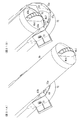
(トナーカートリッジを装着する作業の説明)
図30はトナーカートリッジを保持体に装着する作業の説明図であって、図30Aはトナーカートリッジを下方から前カバーに当てた状態の説明図、図30Bは図30Aに示す状態からトナーカートリッジを傾斜させて上方に押し上げる途中の状態の説明図、図30Cはトナーカートリッジが保持体に装着された状態の説明図である。
図7、図30、図31において、新たなトナーカートリッジKkが装着される場合、画像形成装置Uの上方から傾斜する傾斜ホルダ31に対して、作業者は、一般的に、上方に持ち上げてから乗せようとすると、持ち上げる力が必要になったり、背が低い作業者では困難であり、下方から上方に押し上げるようにして装着することが多い。したがって、トナーカートリッジKkが傾斜ホルダ31に装着される場合に、図30Aに示すように、まず、トナーカートリッジKkの外表面が前カバー71のカートリッジガイド部72aに当てられる。
(Explanation of work to install toner cartridge)
FIG. 30 is an explanatory view of the operation of mounting the toner cartridge on the holding body. FIG. 30A is an explanatory view of the state where the toner cartridge is applied to the front cover from below. FIG. FIG. 30C is an explanatory diagram of a state in which the toner cartridge is mounted on the holding body.
7, 30, and 31, when a new toner cartridge Kk is mounted, the operator generally lifts the
図31はトナーカートリッジを保持体に装着する作業の説明図であって、図31Aは図30Bに対応するトナーカートリッジを上方に押し上げる途中の状態の説明図、図31Bは図30Cに対応するトナーカートリッジが保持体に装着された状態の説明図である。
次に、トナーカートリッジKkがカートリッジガイド部72aに沿って上方に持ち上げながら回転させて、図30B、図31Aに示す状態となる。この状態では、トナーカートリッジKkの傾斜角度に応じて、カートリッジガイド部72aおよびガイド角部63bのいずれかまたは両方向に、トナーカートリッジKkの外表面が接触した状態で、上方に案内される。したがって、カートリッジガイド部72aやガイド角部63bが設けられていない構成に比べて、トナーカートリッジKkの装着が容易になる。
FIG. 31 is an explanatory view of the operation of mounting the toner cartridge on the holding body, FIG. 31A is an explanatory view of a state in which the toner cartridge corresponding to FIG. 30B is being pushed upward, and FIG. 31B is a toner cartridge corresponding to FIG. It is explanatory drawing of the state with which was mounted | worn to the holding body.
Next, the toner cartridge Kk is rotated while being lifted upward along the
また、実施例1では、トナーカートリッジKkの外表面が前端壁63の上端のガイド角部63bで支持されており、トナーカートリッジKkの回転規制片Kk7のように下方に突出する部分が、前端壁63に接触して損傷することが低減されている。
そして、トナーカートリッジKkの前端が、前端壁63より後方まで移動するとトナーカートリッジKkが傾斜ホルダ31に収容され、装着される。
したがって、新たなトナーカートリッジKkがカートリッジ保持面62aに装着され、図6に示す状態となる。図6に示すように、前カバー71が前端開放位置に移動した状態では、回転ロック面54aとサポート連結スタッド44との接触で傾斜ホルダ31が回転不能な状態となっており、且つ、リンク27の被停止部27bと挿入防止用停止部16aとの接触で挿入不能な状態となっている。したがって、前カバー71を閉め忘れた状態で傾斜ホルダ31を回転させたり、挿入することが防止されている。
In the first exemplary embodiment, the outer surface of the toner cartridge Kk is supported by the
When the front end of the toner cartridge Kk moves rearward from the
Therefore, a new toner cartridge Kk is mounted on the
図5、図6において、前カバー71を前端閉塞位置に向けて回転させると、図21に示す状態を経て図20に示す前端閉塞位置に移動する。図20に示す前端閉塞位置では、サポート連結スタッド44が下回転ロック面53bに接触した状態となり、サポート46,47の上方に向けての回転が可能な状態となる。なお、この状態でも、リンク27の被停止部27bと挿入防止用停止部16aとが接触しており、被ガイドレール21,22は挿入不能な状態で保持されている。
5 and 6, when the
前カバー71が前端閉塞位置に移動すると、ロック部材68がコイルバネ69の弾性力で移動規制位置に保持されており、トナーカートリッジKkの回転規制片Kk7が、ロック部68と前端壁63とに挟まれて、回転が規制された状態となる。したがって、カートリッジハンドルKk6を把持した操作中に、カートリッジKkが傾斜ホルダ31に対して回転して、意図した操作とは異なる操作となってしまうことが低減されている。
また、ロック部材68が移動規制位置に保持されており、ロック爪68eが許容規制部67cに係合して、前方への移動が規制されている。したがって、トナーカートリッジKkを回転させる力が作用しても、ロック部材68が前方に押されることが防止されており、許容規制部67cが設けられていない場合に比べて、トナーカートリッジKkが誤って回転することが低減されている。
When the
Further, the
図4、図5において、傾斜ホルダ31を図5に示す傾斜位置から上方に回転させると、図4に示す挿入可能位置に向けて移動する。このとき、実施例1のホルダ回転軸32に組み込まれたワンウェイヒンジ38は、傾斜位置から挿入可能位置に向かう回転方向については回転力が制限されない。したがって、回転方向の一方向だけでなく両方向の回転力を制限する制動部材を使用する場合に比べて、利用者が下方から上方に傾斜ホルダ31を回転させる際に、作業者の回転させようとする力を制限する負荷が作用せず、作業者が容易に挿入可能位置に回転させることが可能になっている。なお、挿入可能位置に上昇中に誤って手を離しても、挿入可能位置から傾斜位置に向けての回転は回転力が制限され、急速度での落下が防止され、作業者が負傷等の事故が低減されている。
また、実施例1の傾斜ホルダ31では、左カバー64の後端保護部64aが左側壁36bと左側の被ガイドレール21との隙間を埋めており、回転作業中に誤って被ガイドレール21と左カバー64との間に指を詰めてしまう等の事故も低減されている。
4 and 5, when the
Further, in the
図4に示す挿入可能位置に移動すると、図15に示すように、サポート46,47のラッチ孔51に掛かり部42dが嵌り、操作する作業者が挿入可能位置に移動したことを認識可能になっている。仮に、操作者が挿入可能位置から、更に上方に回転させようとしても、図15、図17に示すように、サポート連結スタッド44が案内溝部53の上回転ロック面53aに接触している。したがって、サポート46,47の上方への回転が規制されており、傾斜ホルダ31の挿入可能位置よりも上方への回転が規制されている。
また、前記挿入可能位置では、前カバー71のロックスタッド78がカバーロック部56cに嵌った状態となっており、誤って前カバー71が前端開放位置に開放されることが防止されている。
さらに、挿入可能位置では、リンク27が図12に示す停止部離間位置に移動しており、被停止部27bが誤挿入停止部16aから離間し、被ガイドレール21,22を後方の収容位置に向けて移動可能な状態となっている。
When moved to the insertable position shown in FIG. 4, as shown in FIG. 15, the
Further, in the insertable position, the
Further, at the insertable position, the
図3、図4において、図4に示す挿入可能位置から、利用者がカートリッジハンドルKk6を押すと、図24に示すようにトナーカートリッジKkの回転規制片Kk7が上側カバー62の回転規制装着部63a1に接触して、トナーカートリッジKkと共に傾斜ホルダ31および被ガイドレール21,22が図3に示す後方の収容位置に向けて移動する。
このとき、実施例1のトナーカートリッジKkは、回転規制片Kk7がロック部材86に干渉して回転不能な状態で保持されており、流出口部Kk2がシャッタ通過溝6に対応する位置となっている。したがって、流出口部Kk2が干渉せず、シャッタ通過溝6を通過して収容位置に向けて移動可能になっている。
3 and 4, when the user presses the cartridge handle Kk6 from the insertable position shown in FIG. 4, the rotation restricting piece Kk7 of the toner cartridge Kk is turned to the rotation restricting mounting portion 63a1 of the
At this time, in the toner cartridge Kk of Example 1, the rotation restricting piece Kk7 is held in a state where the rotation restricting piece Kk7 cannot rotate due to interference with the lock member 86, and the outflow port Kk2 becomes a position corresponding to the
図21において、傾斜ホルダ31等が挿入可能位置から収容位置に向けて移動し、ロック部材68のロック底壁68bの下面の右部が傾斜面1eに接触すると、コイルバネ69のネジリバネ機能の付勢力に抗して、図27Bに示すように、ロック爪68eが移動規制位置から上方の移動規制解除位置に移動して、ロック部材68が前方に移動可能な状態となる。さらに、傾斜ホルダ31等が挿入されて、収容位置まで移動すると、スライド突起68fがロック解除溝1dの後端面に接触して、図27Cに示すように、ロック爪68eが許容係合部67bに係合し、図28に示すように、ロック部材68のロック前壁68aと回転規制装着部63a1との間に隙間が空いた状態で保持される。
In FIG. 21, when the
したがって、カートリッジハンドルKk6を操作して、トナーカートリッジKkが傾斜ホルダ31に対して回転可能な状態となる。
図3において、収容位置に移動してトナーカートリッジKkの回転規制が解除された状態で、カートリッジハンドルKk6を回転すると、図10Aに示す流出口閉塞位置から図10Cに示す流出口開放位置に移動し、流出口Kk3および流入口9とが開放され、接続される。したがって、トナーカートリッジKkからリザーブタンクRTkに現像剤が供給可能になる。
Therefore, by operating the cartridge handle Kk6, the toner cartridge Kk can be rotated with respect to the
In FIG. 3, when the cartridge handle Kk6 is rotated in the state in which the rotation restriction of the toner cartridge Kk is released after moving to the storage position, the cartridge handle Kk6 moves from the outlet closing position shown in FIG. 10A to the outlet opening position shown in FIG. 10C. The outlet Kk3 and the
図32は実施例2の本体側シャッタの説明図であり、実施例1の図11に対応する図である。
次に本発明の実施例2の説明をするが、この実施例2の説明において、前記実施例1の構成要素に対応する構成要素には同一の符号を付して、その詳細な説明は省略する。
この実施例は下記の点で、前記実施例1と相違しているが、他の点では前記実施例1と同様に構成される。
図32において、実施例2の本体側シャッタ12′では、実施例1の本体側シャッタ12のリブ12hが省略されている。そして、リブ12hに替えて、流入口形成部7に、突出部の一例として、上げ底部12f側に向けて突出するガイドリブ7aが形成されている。実施例2における上げ底部12fの左右方向の幅やガイドリブ7aの位置および大きさは、本体側シャッタ12′の流出口開放位置と流出口閉塞位置との間の移動範囲を妨げないように設定されている。
FIG. 32 is an explanatory diagram of the main body side shutter of the second embodiment, and corresponds to FIG. 11 of the first embodiment.
Next, a second embodiment of the present invention will be described. In the description of the second embodiment, components corresponding to the components of the first embodiment are denoted by the same reference numerals, and detailed description thereof is omitted. To do.
This embodiment is different from the first embodiment in the following points, but is configured in the same manner as the first embodiment in other points.
In FIG. 32, the
(実施例2の作用)
前記構成を備えた実施例2の画像形成装置Uでは、本体側シャッタ12′の上げ底部12fと、流入口形成部7との間に擦り切り抑制空間12gが設けられた状態で本体側シャッタ12′が移動する。したがって、本体側シャッタ12′が流出口閉塞位置に移動する際に、流入口形成部7表面に付着した現像剤が本体側シャッタ12′で擦り切られることが抑制される。
(Operation of Example 2)
In the image forming apparatus U according to the second embodiment having the above-described configuration, the main
(変更例)
以上、本発明の実施例を詳述したが、本発明は、前記実施例に限定されるものではなく、特許請求の範囲に記載された本発明の要旨の範囲内で、種々の変更を行うことが可能である。本発明の変更例(H01)〜(H019)を下記に例示する。
(H01)前記実施例において、前記画像形成装置Uは、いわゆる、複合機により構成したが、これに限定されず、例えば、プリンタ、FAX等により構成することも可能である。(H02)前記実施例において、前記画像形成装置Uは、6色のトナーが使用される構成に限定されず、例えば、5色以下や、7色以上のトナーを使用する構成も可能である。
(Example of change)
As mentioned above, although the Example of this invention was explained in full detail, this invention is not limited to the said Example, A various change is performed within the range of the summary of this invention described in the claim. It is possible. Modification examples (H01) to (H019) of the present invention are exemplified below.
(H01) In the above embodiment, the image forming apparatus U is configured by a so-called multi-function machine, but is not limited thereto, and may be configured by, for example, a printer, a FAX, or the like. (H02) In the above-described embodiment, the image forming apparatus U is not limited to the configuration using six colors of toner, and may be configured to use, for example, five colors or less or seven colors or more of toner.
(H03)前記実施例において、G:グリーン、O:オレンジ、Y:イエロー、M:マゼンタ、C:シアン、K:黒の6色のトナーを使用したが、これに限定されず、例えば、G:グリーン、O:オレンジのトナーに替えて、前記6色以外の色のトナーを使用することも可能である。また、他にも、防水、保護のために画像表面をコーティングする無色トナーや、企業や団体等の組織を象徴する色、いわゆるコーポレートカラーとしたり、盗難防止等のために印刷用紙の画像内に予め設定された形状、配列、例えば、線状の磁気ワイヤを形成するための磁気トナーを使用することも可能である。なお、磁気ワイヤから発生する磁気パルスを検出する盗難防止装置については、例えば、特開2006−256124号公報等に記載されており、公知である。 (H03) In the above embodiment, toners of six colors of G: green, O: orange, Y: yellow, M: magenta, C: cyan, and K: black are used. However, the present invention is not limited to this. : It is also possible to use toners of colors other than the above six colors instead of the green and O: orange toners. In addition, colorless toner that coats the surface of the image for waterproofing and protection, colors that symbolize organizations such as companies and organizations, so-called corporate colors, and in the image of printing paper to prevent theft It is also possible to use a magnetic toner for forming a preset shape and arrangement, for example, a linear magnetic wire. An anti-theft device for detecting a magnetic pulse generated from a magnetic wire is described in, for example, Japanese Patent Application Laid-Open No. 2006-256124, and is well known.
(H04)前記実施例において、制動部材の一例としてワンウェイヒンジを使用する構成を例示したが、ワンウェイヒンジを使用することが好ましいが、例えば、正逆回転両方向に制動をするトルクリミッタを使用することも可能である。また、この他にも、速度が増加するのに応じて負荷抵抗が大きくなる緩衝装置、いわゆるダンパーを制動部材として使用することも可能である。なお、制動部材を設けることが望ましいが、省略することも可能である。
(H05)前記実施例において、引き出し体の一例としてのレール状の被ガイドレール21,22を例示したが、この構成に限定されず、いわゆるスライダ等の従来公知の引き出し方向に移動可能な構成を使用することが可能である。
(H04) In the above-described embodiment, the configuration using a one-way hinge as an example of a braking member is illustrated. However, it is preferable to use a one-way hinge, but for example, a torque limiter that performs braking in both forward and reverse rotation directions is used. Is also possible. In addition to this, it is also possible to use a shock absorber, a so-called damper, whose load resistance increases as the speed increases, as a braking member. Although it is desirable to provide a braking member, it can be omitted.
(H05) In the above-described embodiment, the rail-shaped guided
(H06)前記実施例において、トナーカートリッジKk〜Kgが傾斜ホルダ31に装着される際に、回転位置が流出口閉塞位置から流出口開放位置側にずれる可能性があるが、これに対応するために、前カバー71を閉じる際に、トナーカートリッジKk〜Kgを流出口閉塞位置に回転させる機構を組み込むことが望ましい。例えば、ハンドルロック81にトナーカートリッジKk〜Kgの前端に接触して回転させるカムを設けて、前カバー71を閉じる動作に伴って、流出口閉塞位置に移動させることも可能である。
(H07)前記実施例において、リンク27を設けて傾斜ホルダ31が挿入可能位置に移動していない状態で被ガイドレール21,22が引き出し位置で保持される構成を採用することが望ましいが、省略することも可能である。
(H06) In the above embodiment, when the toner cartridges Kk to Kg are mounted on the
(H07) In the above-described embodiment, it is desirable to adopt a configuration in which the guide rails 21 and 22 are held at the pull-out position in a state where the
(H08)前記実施例において、掛かり部42dとラッチ孔51とによる掛かりで、作業者に挿入可能位置に移動したことを知覚させたり、挿入可能位置で傾斜ホルダ31を保持する補助をしたりする構成を採用することが望ましいが、省略することも可能である。また、ピン42とラッチ孔51との組み合わせを採用したが、この構成に限定されず、例えば、かぎ爪と孔や、かぎ爪とピンといった組み合わせ等、従来公知の任意の構成とすることも可能である。また、ピン42をホルダフレーム36に設け、ラッチ孔51をサポート46,47に設けたが、ホルダフレーム36にラッチ孔を設け、サポートにピンを設けることも可能である。
(H09)前記実施例において、サポート46,47と前カバー71との回転の連動により、回転ロック面54aとサポート連結スタッド44とが嵌り、前カバー71を前端閉塞位置に移動させないと傾斜ホルダ31が回転不能な状態にロックする構成を採用することが望ましいが、省略することも可能である。
(H08) In the above-described embodiment, the hook by the
(H09) In the above-described embodiment, the
(H010)前記実施例において、回転規制片Kk7とリブ接触部62bとの接触で、カートリッジハンドルKk6を操作して引き出し位置から収容位置まで移動可能な構成を例示したが、この構成に限定されず、押し込む構成は任意の構成を採用可能である。例えば、トナーカートリッジKkの前端を前カバーで完全に覆い、前カバー71等に操作部を設けて前カバー71を押し込むことで収容位置に向けて移動可能な構成とすることも可能である。
(H011)前記実施例において、ホルダカバー61は設けることが望ましいが、省略することも可能であり、ホルダカバー61の各部位をホルダフレーム36に設けることも可能である。
(H010) In the above-described embodiment, the configuration in which the cartridge handle Kk6 can be operated by the contact between the rotation restricting piece Kk7 and the
(H011) In the above embodiment, the
(H012)前記実施例において、ロックスタッド78とロック開口56とにより、前カバー71の回転と、サポート46,47とを連動させる構成を例示したが、この構成を設けることが望ましいが、省略して、独立して移動可能な構成とすることも可能である。また、スタッド78と開口56との組み合わせに限定されず、任意の連動機構とすることも可能であり、スタッド78をサポート46,47に設け、開口を前カバーに設けることも可能である。
(H013)前記実施例において、ロック部材68の形状や構成等は、実施例に例示した構成に限定されず、設計や仕様等に応じて変更可能である。なお、ロック部材68は設けることが望ましいが、省略することも可能である。
(H012) In the above-described embodiment, the configuration in which the rotation of the
(H013) In the above embodiment, the shape and configuration of the locking
(H014)前記実施例において、ガイド角部63bや開口63aの形状は、例示した形状に限定されず、任意の形状とすることが可能である。例えば、開口の形状63aを、回転規制片Kk7が回転規制装着部63a1にガイドされるように、カートリッジハンドルKk6をガイドする縦方向や斜め方向の形状とすることも可能である。なお、ガイド角部63bは省略することも可能である。
(H015)前記実施例において、カートリッジガイド部72aの形状は、例示した形状に限定されず、任意の形状とすることが可能である。例えば、カートリッジガイド部72bの左右方向の長さを長くしたり、高さを高くしたり等、任意の構成とすることが可能である。なお、カートリッジガイド部72aは省略することも可能である。
(H014) In the above embodiment, the shape of the
(H015) In the above-described embodiment, the shape of the
(H016)前記実施例において、擦り切り抑制空間12gの大きさ、すなわち、前後方向の幅や左右方向の長さは、実施例に例示した構成に限定されず、任意の大きさとすることが可能である。例えば、本体側シャッタ12の移動方向に沿った長さは、本体側シャッタ12の全域としたり、対向部12eの近傍のみとすることも可能である。
(H017)前記実施例において、現像剤ポケット6aの形状は任意に変更可能である。また、現像剤ポケット6aを設けることが望ましいが、省略することも可能である。
(H018)前記実施例において、本体側シャッタ12が閉塞位置に移動した状態で、対向部12eの右側に微小な隙間を形成する構成を例示したが、これに限定されず、隙間の大きさは設計等に応じて任意に変更可能である。また、隙間を形成することが望ましいが、省略することも可能である。
(H016) In the embodiment described above, the size of the fraying
(H017) In the embodiment, the shape of the
(H018) In the above-described embodiment, the configuration in which the minute gap is formed on the right side of the facing
(H019)前記実施例において、トナーカートリッジKg〜Kkは、カートリッジシャッタKk4が周面に沿って周方向に移動する構成を採用しているが、この構成に限定されず、例えば、引き出し方向に沿って移動可能な構成とし、引き出し位置と収容位置との間を移動する際に開閉される構成を採用することも可能である。 (H019) In the above-described embodiment, the toner cartridges Kg to Kk adopt a configuration in which the cartridge shutter Kk4 moves in the circumferential direction along the circumferential surface. However, the configuration is not limited to this configuration. It is also possible to adopt a configuration that can be opened and closed, and that is opened and closed when moving between the drawer position and the storage position.
6a…落下現像剤収容部、
7a,12h…突出部
9…流入口,通過口、
12…開閉部材、
12f…擦り切り抑制部、
12g…擦り切り抑制空間、
Gy,Gm,Gc,Gk,Go,Gg…現像器、
Kk1…収容部、
Kk3…流出口、
Ky,Km,Kc,Kk,Ko,Kg…現像剤収容容器、
Py,Pm,Pc,Pk,Po,Pg…像保持体、
RT1,RT2…搬送部材、
U…画像形成装置、
U3a…現像剤供給装置。
6a ... Falling developer container,
7a, 12h ...
12 ... Opening / closing member,
12f ... a fraying suppression part,
12g ... a fraying suppression space,
Gy, Gm, Gc, Gk, Go, Gg ... developer,
Kk1 ... accommodating part,
Kk3 ... Outlet,
Ky, Km, Kc, Kk, Ko, Kg ... developer container,
Py, Pm, Pc, Pk, Po, Pg ... Image carrier,
RT1, RT2 ... conveying member,
U: Image forming apparatus,
U3a: developer supply device.
Claims (5)
前記流出口と接続可能に構成され、前記流出口から流出した現像剤が流入する流入口と、
前記流入口を開放する開放位置と、前記流入口を閉塞する閉塞位置との間を移動可能に支持された開閉部材であって、前記開放位置から前記閉塞位置に向かう閉塞方向の前端に対して前記流入口の縁側に向けて突出し且つ前記開放位置と前記閉塞位置との間で移動する方向に対して交差する方向の両側に設けられた突出部と、を有し、前記開放位置から前記閉塞位置に向かう閉塞方向の前記開閉部材の前端に前記流入口の縁の表面に対して離間して形成された擦り切り抑制部を備える前記開閉部材と、
前記流入口から流入した現像剤を搬送する搬送部材と、
を備えたことを特徴とする現像剤供給装置。 A developer storage container having a storage portion in which the developer is stored, and an outlet through which the developer in the storage portion flows out;
An inflow port configured to be connectable to the outflow port, and into which the developer flowing out from the outflow port flows;
An open / close member supported to be movable between an open position for opening the inlet and a closed position for closing the inlet, with respect to the front end in the closing direction from the open position toward the closed position Projecting toward the edge side of the inflow port, and projecting portions provided on both sides in a direction intersecting the direction of movement between the open position and the closed position, and from the open position to the closed position It said closing member having a leveling suppressing portion formed spaced apart with respect to the inlet edge surface of the front end of the closing direction of the closing member towards the position,
A transport member for transporting the developer flowing in from the inflow port;
A developer supply apparatus comprising:
前記流出口と接続可能に構成され、前記流出口から流出した現像剤が流入する流入口と、
前記流入口を開放する開放位置と、前記流入口を閉塞する閉塞位置との間を移動可能に支持された開閉部材と、
前記流入口の縁に設けられ、前記開放位置から前記閉塞位置に向かう閉塞方向の前端側に向けて突出して形成され且つ前記開放位置と前記閉塞位置との間で移動する方向に対して交差する方向の両側に設けられた突出部と、
前記流入口から流入した現像剤を搬送する搬送部材と、
を備え、
前記開放位置から前記閉塞位置に向かう閉塞方向の前記開閉部材の前端に、前記流入口の縁の表面に対して離間した擦り切り抑制部が形成されたことを特徴とする現像剤供給装置。 A developer storage container having a storage portion in which the developer is stored, and an outlet through which the developer in the storage portion flows out;
An inflow port configured to be connectable to the outflow port, and into which the developer flowing out from the outflow port flows;
An opening / closing member supported so as to be movable between an open position for opening the inlet and a closed position for closing the inlet;
Provided at the edge of the inflow port, projecting toward the front end side in the closing direction from the opening position toward the closing position, and intersecting the direction of movement between the opening position and the closing position Protrusions provided on both sides of the direction;
A transport member for transporting the developer flowing in from the inflow port;
With
The open front end of the opening and closing member of the closing direction toward the closed position from the position, the developer supply device, characterized in that leveling suppressing portion is separated from the surface of the edge of the inlet port is formed.
を備えたことを特徴とする請求項1または2に記載の現像剤供給装置。 A falling developer accommodating portion formed further forward of the front end of the closing direction of the opening / closing member moved to the closing position and capable of accommodating the dropped developer;
The developer supply device according to claim 1, further comprising:
前記像保持体表面の潜像を可視像に現像する現像器と、
前記現像器に補給される現像剤が収容され収容された収容部と、前記収容部の現像剤が流出する流出口と、を有する現像剤収容容器と、
前記流出口と接続可能に構成され、前記流出口から流出した現像剤が流入する流入口と、
前記流入口を開放する開放位置と、前記流入口を閉塞する閉塞位置との間を移動可能に支持された開閉部材であって、前記開放位置から前記閉塞位置に向かう閉塞方向の前端に対して前記流入口の縁側に向けて突出し且つ前記開放位置と前記閉塞位置との間で移動する方向に対して交差する方向の両側に設けられた突出部と、を有し、前記開放位置から前記閉塞位置に向かう閉塞方向の前記開閉部材の前端に前記流入口の縁の表面に対して離間して形成された擦り切り抑制部を備える前記開閉部材と、
前記流入口から流入した現像剤を前記現像器に搬送する搬送部材と、
を備えたことを特徴とする画像形成装置。 An image carrier,
A developing unit for developing the latent image on the surface of the image carrier into a visible image;
A developer container having a container in which the developer to be replenished in the developer is stored and stored; and an outlet through which the developer in the container flows out;
An inflow port configured to be connectable to the outflow port, and into which the developer flowing out from the outflow port flows;
An open / close member supported to be movable between an open position for opening the inlet and a closed position for closing the inlet, with respect to the front end in the closing direction from the open position toward the closed position Projecting toward the edge side of the inflow port, and projecting portions provided on both sides in a direction intersecting the direction of movement between the open position and the closed position, and from the open position to the closed position The opening / closing member provided with a fray-off suppressing portion formed at a front end of the opening / closing member in a closing direction toward the position and spaced from a surface of an edge of the inflow port ;
A transport member for transporting the developer flowing in from the inlet to the developer;
An image forming apparatus comprising:
前記像保持体表面の潜像を可視像に現像する現像器と、
前記現像器に補給される現像剤が収容され収容された収容部と、前記収容部の現像剤が流出する流出口と、を有する現像剤収容容器と、
前記流出口と接続可能に構成され、前記流出口から流出した現像剤が流入する流入口と、
前記流入口を開放する開放位置と、前記流入口を閉塞する閉塞位置との間を移動可能に支持された開閉部材であって、
前記流入口の縁に設けられ、前記開放位置から前記閉塞位置に向かう閉塞方向の前端側に向けて突出して形成され且つ前記開放位置と前記閉塞位置との間で移動する方向に対して交差する方向の両側に設けられた突出部と、
前記流入口から流入した現像剤を前記現像器に搬送する搬送部材と、
を備え、
前記開放位置から前記閉塞位置に向かう閉塞方向の前記開閉部材の前端に、前記流入口の縁の表面に対して離間した擦り切り抑制部が形成されたことを特徴とする画像形成装置。 An image carrier,
A developing unit for developing the latent image on the surface of the image carrier into a visible image;
A developer container having a container in which the developer to be replenished in the developer is stored and stored; and an outlet through which the developer in the container flows out;
An inflow port configured to be connectable to the outflow port, and into which the developer flowing out from the outflow port flows;
An opening / closing member supported so as to be movable between an open position for opening the inlet and a closed position for closing the inlet;
Provided at the edge of the inflow port, projecting toward the front end side in the closing direction from the opening position toward the closing position, and intersecting the direction of movement between the opening position and the closing position Protrusions provided on both sides of the direction;
A transport member for transporting the developer flowing in from the inlet to the developer;
With
An image forming apparatus , wherein a fraying suppression portion is formed at a front end of the opening / closing member in a closing direction from the open position toward the closing position, and is separated from a surface of an edge of the inflow port .
Priority Applications (2)
| Application Number | Priority Date | Filing Date | Title |
|---|---|---|---|
| JP2009236111A JP5504814B2 (en) | 2009-10-13 | 2009-10-13 | Developer supply apparatus and image forming apparatus |
| US12/857,081 US8494417B2 (en) | 2009-10-13 | 2010-08-16 | Opening/closing member, developer supplying apparatus, and image forming apparatus |
Applications Claiming Priority (1)
| Application Number | Priority Date | Filing Date | Title |
|---|---|---|---|
| JP2009236111A JP5504814B2 (en) | 2009-10-13 | 2009-10-13 | Developer supply apparatus and image forming apparatus |
Publications (3)
| Publication Number | Publication Date |
|---|---|
| JP2011085633A JP2011085633A (en) | 2011-04-28 |
| JP2011085633A5 JP2011085633A5 (en) | 2012-10-25 |
| JP5504814B2 true JP5504814B2 (en) | 2014-05-28 |
Family
ID=43854943
Family Applications (1)
| Application Number | Title | Priority Date | Filing Date |
|---|---|---|---|
| JP2009236111A Active JP5504814B2 (en) | 2009-10-13 | 2009-10-13 | Developer supply apparatus and image forming apparatus |
Country Status (2)
| Country | Link |
|---|---|
| US (1) | US8494417B2 (en) |
| JP (1) | JP5504814B2 (en) |
Families Citing this family (14)
| Publication number | Priority date | Publication date | Assignee | Title |
|---|---|---|---|---|
| JP5648598B2 (en) * | 2011-07-25 | 2015-01-07 | コニカミノルタ株式会社 | Image forming apparatus and toner bottle |
| US8873996B1 (en) | 2013-05-29 | 2014-10-28 | Lexmark International, Inc. | Toner system for an image forming device including a toner cartridge having a shutter with bypassing actuation |
| JP6366423B2 (en) * | 2014-08-20 | 2018-08-01 | キヤノン株式会社 | Developer container, process cartridge, and image forming apparatus |
| JP6586740B2 (en) * | 2015-03-06 | 2019-10-09 | 富士ゼロックス株式会社 | Image forming apparatus |
| JP1550182S (en) * | 2015-10-15 | 2016-05-30 | ||
| US9563169B1 (en) | 2015-12-14 | 2017-02-07 | Lexmark International, Inc. | Replaceable unit for an electrophotographic image forming device having a retractable electrical connector |
| JP2018012143A (en) * | 2016-07-19 | 2018-01-25 | 株式会社デンソー | Robot device |
| JP7024264B2 (en) * | 2017-09-04 | 2022-02-24 | 富士フイルムビジネスイノベーション株式会社 | Image forming device |
| US20210146691A1 (en) * | 2018-08-30 | 2021-05-20 | Hewlett-Packard Development Company, L.P. | Mating interface gaskets |
| CN111458997B (en) * | 2019-01-21 | 2023-02-14 | 江西凯利德科技有限公司 | Developer container and image forming apparatus including the same |
| US10698363B1 (en) | 2019-04-12 | 2020-06-30 | Lexmark International, Inc. | Electrical connection for an imaging unit of an electrophotographic image forming device |
| US10649389B1 (en) | 2019-04-12 | 2020-05-12 | Lexmark International, Inc. | Electrical connectors of a replaceable unit of an electrophotographic image forming device |
| US10649399B1 (en) | 2019-04-12 | 2020-05-12 | Lexmark Internatioanl, Inc. | Replaceable unit for an electrophotographic image forming device having a magnetic sensor |
| US10761476B1 (en) | 2019-04-12 | 2020-09-01 | Lexmark International, Inc. | Replaceable unit for an electrophotographic image forming device having a movable electrical connector |
Family Cites Families (18)
| Publication number | Priority date | Publication date | Assignee | Title |
|---|---|---|---|---|
| JPH071644Y2 (en) * | 1988-05-23 | 1995-01-18 | 富士ゼロックス株式会社 | Toner supply device for image forming apparatus |
| JP3468514B2 (en) | 1992-12-30 | 2003-11-17 | 株式会社リコー | Developer supply device |
| JPH10213959A (en) | 1997-01-30 | 1998-08-11 | Konica Corp | Developer replenishment device and image forming device |
| JPH11143190A (en) | 1997-11-11 | 1999-05-28 | Canon Inc | Toner replenishing vessel and electrophotographic image forming device |
| JP3437766B2 (en) * | 1998-07-01 | 2003-08-18 | 京セラミタ株式会社 | Toner supply device |
| JP2000275946A (en) | 1999-03-29 | 2000-10-06 | Ricoh Co Ltd | Toner replenishing device |
| JP3450741B2 (en) * | 1999-03-29 | 2003-09-29 | キヤノン株式会社 | Toner supply container |
| JP4289750B2 (en) * | 2000-01-13 | 2009-07-01 | キヤノン株式会社 | Toner supply container |
| JP3952705B2 (en) | 2001-05-29 | 2007-08-01 | コニカミノルタホールディングス株式会社 | Image forming apparatus |
| JP2003114568A (en) | 2001-10-05 | 2003-04-18 | Canon Inc | Electrophotographic image forming device and toner supply container |
| JP2003122114A (en) * | 2001-10-19 | 2003-04-25 | Hitachi Koki Co Ltd | Toner replenishment device |
| JP4307009B2 (en) | 2002-04-03 | 2009-08-05 | キヤノン株式会社 | Developer supply device |
| JP2003107871A (en) * | 2002-07-17 | 2003-04-09 | Canon Inc | Toner replenishing container |
| JP2004126407A (en) | 2002-10-07 | 2004-04-22 | Konica Minolta Holdings Inc | Image forming device |
| JP2005031229A (en) * | 2003-07-09 | 2005-02-03 | Fuji Xerox Co Ltd | Toner cartridge |
| JP4006426B2 (en) * | 2004-09-08 | 2007-11-14 | キヤノン株式会社 | Developer supply device and image forming apparatus |
| JP2006215239A (en) | 2005-02-03 | 2006-08-17 | Konica Minolta Business Technologies Inc | Image forming device |
| JP2007310148A (en) * | 2006-05-18 | 2007-11-29 | Toshiba Corp | Toner cartridge |
-
2009
- 2009-10-13 JP JP2009236111A patent/JP5504814B2/en active Active
-
2010
- 2010-08-16 US US12/857,081 patent/US8494417B2/en active Active
Also Published As
| Publication number | Publication date |
|---|---|
| US20110085825A1 (en) | 2011-04-14 |
| JP2011085633A (en) | 2011-04-28 |
| US8494417B2 (en) | 2013-07-23 |
Similar Documents
| Publication | Publication Date | Title |
|---|---|---|
| JP5504814B2 (en) | Developer supply apparatus and image forming apparatus | |
| US8406652B2 (en) | Removable member-holding device and image forming apparatus | |
| US7738817B2 (en) | Developer supply container and image forming apparatus | |
| US7539445B2 (en) | Developer supply container and image forming apparatus | |
| JP5609559B2 (en) | Developer transport device and image forming apparatus | |
| JP2007065066A (en) | Image forming apparatus | |
| JP5910015B2 (en) | Developer transport device and image forming apparatus | |
| US10527999B2 (en) | Cartridge unit and image forming apparatus having features to prevent erroneous cartridge unit locking | |
| JP5423082B2 (en) | Detachable body holding device and image forming apparatus | |
| JP5509780B2 (en) | Toner cartridge holding device and image forming apparatus | |
| JP5218124B2 (en) | Developer supply apparatus and image forming apparatus | |
| JP5417924B2 (en) | Detachable body holding device and image forming apparatus | |
| JP5476757B2 (en) | Detachable body holding device and image forming apparatus | |
| JP5402493B2 (en) | Detachable body holding device and image forming apparatus | |
| EP2911006B1 (en) | Toner conveying device and image forming apparatus including the same |
Legal Events
| Date | Code | Title | Description |
|---|---|---|---|
| A521 | Request for written amendment filed |
Free format text: JAPANESE INTERMEDIATE CODE: A523 Effective date: 20120911 |
|
| A621 | Written request for application examination |
Free format text: JAPANESE INTERMEDIATE CODE: A621 Effective date: 20120911 |
|
| A977 | Report on retrieval |
Free format text: JAPANESE INTERMEDIATE CODE: A971007 Effective date: 20130909 |
|
| A131 | Notification of reasons for refusal |
Free format text: JAPANESE INTERMEDIATE CODE: A131 Effective date: 20130917 |
|
| A977 | Report on retrieval |
Free format text: JAPANESE INTERMEDIATE CODE: A971007 Effective date: 20131030 |
|
| TRDD | Decision of grant or rejection written | ||
| A01 | Written decision to grant a patent or to grant a registration (utility model) |
Free format text: JAPANESE INTERMEDIATE CODE: A01 Effective date: 20140218 |
|
| A61 | First payment of annual fees (during grant procedure) |
Free format text: JAPANESE INTERMEDIATE CODE: A61 Effective date: 20140303 |
|
| R150 | Certificate of patent or registration of utility model |
Ref document number: 5504814 Country of ref document: JP Free format text: JAPANESE INTERMEDIATE CODE: R150 |
|
| S533 | Written request for registration of change of name |
Free format text: JAPANESE INTERMEDIATE CODE: R313533 |
|
| R350 | Written notification of registration of transfer |
Free format text: JAPANESE INTERMEDIATE CODE: R350 |