JP4288993B2 - Tube pump and liquid injection device - Google Patents
Tube pump and liquid injection device Download PDFInfo
- Publication number
- JP4288993B2 JP4288993B2 JP2003101868A JP2003101868A JP4288993B2 JP 4288993 B2 JP4288993 B2 JP 4288993B2 JP 2003101868 A JP2003101868 A JP 2003101868A JP 2003101868 A JP2003101868 A JP 2003101868A JP 4288993 B2 JP4288993 B2 JP 4288993B2
- Authority
- JP
- Japan
- Prior art keywords
- flexible tube
- opening
- tube
- auxiliary
- end side
- Prior art date
- Legal status (The legal status is an assumption and is not a legal conclusion. Google has not performed a legal analysis and makes no representation as to the accuracy of the status listed.)
- Expired - Fee Related
Links
Images


Classifications
-
- B—PERFORMING OPERATIONS; TRANSPORTING
- B41—PRINTING; LINING MACHINES; TYPEWRITERS; STAMPS
- B41J—TYPEWRITERS; SELECTIVE PRINTING MECHANISMS, i.e. MECHANISMS PRINTING OTHERWISE THAN FROM A FORME; CORRECTION OF TYPOGRAPHICAL ERRORS
- B41J2/00—Typewriters or selective printing mechanisms characterised by the printing or marking process for which they are designed
- B41J2/005—Typewriters or selective printing mechanisms characterised by the printing or marking process for which they are designed characterised by bringing liquid or particles selectively into contact with a printing material
- B41J2/01—Ink jet
- B41J2/17—Ink jet characterised by ink handling
- B41J2/175—Ink supply systems ; Circuit parts therefor
- B41J2/17596—Ink pumps, ink valves
Description
【0001】
【発明の属する技術分野】
本発明は、チューブポンプおよび液体噴射装置に関し、詳しくは、静かに動作することのできるものに関する。
【0002】
【従来の技術】
従来より、チューブ内に負圧を発生させて流体を一端側から吸引し他端側から吐出させるチューブポンプが知られており、このチューブポンプは、簡易かつコンパクトな構成であることから、流体を利用する多種多様な装置に搭載されている。
【0003】
例えば、チューブポンプは、インク(液状流体)を記録ヘッドのノズルから吐出(噴射)して記録紙に画像形成するインクジェット記録装置(液体噴射装置)に搭載されているものがあり、その記録ヘッドを快適に動作させるためのヘッドクリーニングのタイミングにノズル内からインクを吸引するように動作する(例えば、特許文献1、2参照。)。
【0004】
この特許文献1、2に記載のチューブポンプは、図19および図20に示すように、可撓性チューブ1を円筒形状のケース2内に収容する状態で、ローラ3がケース2の内壁面2aに向かって可撓性チューブ1を押圧して押し潰しつつ回転移動する。このチューブポンプは、ローラ3により押し潰される可撓性チューブ1の押圧箇所が上流側から下流側へと繰り返し巡廻移動することにより、その上流側に負圧を生じさせて可撓性チューブ1の上流側からインクを吸引し下流側から吐出させることができる。
【0005】
【特許文献1】
特開2001−301195号公報
【特許文献2】
特開平7−253082号公報
【0006】
【発明が解決しようとする課題】
しかしながら、この特許文献1に記載のチューブポンプ(図19に図示)および特許文献2に記載のチューブポンプ(図20に図示)のいずれも、可撓性チューブ1がケース2の内部または外部で交差して重なる部分1a、1bを有することから、その重なり方向のスペースが嵩んで薄型化を図る場合に妨げとなっていた。
【0007】
また、インクジェット記録装置のカラー化に伴って、カラーインク用とブラックインク用として2本の可撓性チューブ1を一体化する場合があり、この場合には、4本の可撓性チューブ1が重なることになって、その重なり方向のスペースがより嵩んでしまって、不都合がより顕著になる。
【0008】
このような不都合を解消するために、図21に示すように、ケース2の内壁面2aの一部に開口部2bを設けて、重なり部分が生じないようにその開口部2bから可撓性チューブ1を引き出してそのまま振り分ける構成を採用することが考えられる。
【0009】
ただし、このような構成を採用するチューブポンプにあっては、ケース2の開口部2bに対応する箇所(図21に破線で示す位置)において、ローラ3は押圧する可撓性チューブ1の周面を瞬間的に下流側から再度上流側に乗り換えることになる。このため、その乗換時に、ローラ3が可撓性チューブ1の周面の変化に追従して急激に移動したときに発生する衝突音が問題になる場合がある。また、その乗換時に、ローラ3による可撓性チューブ1の押し潰しが甘くなって、可撓性チューブ1内が瞬間的に連通して負圧が開放されてしまう場合がある。なお、このような問題は、特許文献2に記載のチューブポンプ(図20に図示)においても同様に発生する。
【0010】
そこで、本発明は、可撓性チューブの周面を押圧する部材が安定して回転移動などして、また、その可撓性チューブの押し潰しを解消しないようにすることにより、静かに、また、効率よく、動作させることのできるチューブポンプおよび液体噴射装置を提供することを目的とする。
【0011】
【課題を解決するための手段】
上記課題を解決するチューブポンプの第1の発明は、流体の流路を内部に画成されている可撓性チューブと、該可撓性チューブを内壁面に沿うように収容する収容ケースと、該収容ケースの内壁面に向かって可撓性チューブの一部を押し潰すように押圧しつつ当該押圧箇所を該可撓性チューブの一端側から他端側に繰り返し巡廻移動する押圧部材とを備えて、可撓性チューブの押圧箇所が移動することにより上流側内圧を減圧させて該可撓性チューブの流路内に流体を一端側から吸引して他端側から吐出させるチューブポンプであって、可撓性チューブが出入り可能に収容ケースの内壁面に開口する開口部と、収容ケースの開口部近傍に設けられて可撓性チューブの内壁面から離隔する周面に滑らかに連続する補助面を形成された補助部材とを有し、補助部材が収容ケースの開口部近傍を通過する押圧部材を可撓性チューブの他端側から一端側に受け渡すことを特徴とするものである。
【0012】
この発明では、可撓性チューブの収容ケースは、円形や楕円形などに限らず、異形であっても滑らかに連続する内壁面を有すればよく、可撓性チューブの出入りする(引き出し/引き入れする)開口部は1箇所に限らず、2箇所以上でもよい。この場合に、押圧部材は、収容ケースの内壁面に沿うように開口部に近接する方向に移動するとき、可撓性チューブの周面に滑らかに連続する補助部材の補助面を押圧しつつその補助面に乗り上げる。そして、その押圧部材は、収容ケースの開口部から離隔する方向にさらに移動しようとするとき、可撓性チューブの周面に滑らかに連続する補助部材の補助面からその可撓性チューブの周面に乗り換える。したがって、押圧部材は、可撓性チューブの出入りする開口部を通過する際に、乗換先の可撓性チューブの周面に衝突するように急激に追従移動することを回避することができ、可撓性チューブなどとの衝突音をなくすことができる。
【0013】
上記課題を解決するチューブポンプの第2の発明は、上記第1の発明の特定事項に加え、前記補助部材は、収容ケースの開口部における内壁面の延長面よりも内側で該延長面と略平行となるように延在する補助面を形成されて、大きく弾性変形可能な弾性材料により作製されていることを特徴とするものである。
【0014】
この発明では、押圧部材は、収容ケースの内壁面に沿うように移動して可撓性チューブを押し潰す押圧箇所を移動させる。この押圧部材は、収容ケースの開口部近傍では、押し潰す可撓性チューブの周面から内壁面の延長面に略平行な補助部材の補助面に滑らかに乗り上げて、その補助部材をも弾性変形させつつ、そのまま反対側の可撓性チューブの周面に滑らかに乗り換える。したがって、押圧部材は、可撓性チューブの出入りする開口部を通過する際に、可撓性チューブの下流側から再度上流側に滑らかに乗り換えることができ、乗換先の可撓性チューブの周面に衝突するように急激に追従移動して衝突音を発生させてしまうことがない。
【0015】
上記課題を解決するチューブポンプの第3の発明は、上記第1の発明の特定事項に加え、前記補助部材は、可撓性チューブの他端側から開口部に近接するように移動する押圧部材に当接したときに該可撓性チューブの他端側を押し潰すように回動して当該他端側周面に滑らかに連続する補助面を形成し、該補助面に押圧部材が乗り上げて回動軸を超えたときには可撓性チューブの一端側を押し潰すように回動して当該一端側周面に滑らかに連続する補助面を形成し、押圧部材が離隔したときには可撓性チューブの押し潰しを解除するように回動して復帰することを特徴とするものである。
【0016】
この発明では、押圧部材は、収容ケースの内壁面に沿うように移動して可撓性チューブを押し潰す押圧箇所を移動させる。この押圧部材は、収容ケースの開口部に近接する方向に移動するとき、当接する補助部材を回動させて滑らかに連続する補助面に乗り上げる。そして、押圧部材は、補助部材の回動軸を越えて収容ケースの開口部から離隔する方向にさらに移動しようとするとき、補助部材を反対方向に回動させてその補助面から滑らかに連続する可撓性チューブの周面に乗り換える。この乗換後には、補助部材は可撓性チューブの押し潰しを解除するように回動復帰する。したがって、押圧部材は、可撓性チューブの出入りする開口部を通過する際に、瞬間かつ微小な可撓性チューブの押し潰し解消のみで、その可撓性チューブの下流側から再度上流側に滑らかに乗り換えることができ、乗換先の可撓性チューブの周面に衝突するように急激に追従移動して衝突音を発生させてしまうことがない。
【0017】
上記課題を解決するチューブポンプの第4の発明は、上記第1の発明の特定事項に加え、前記補助部材は、収容ケースの開口部に近接するように移動する押圧部材に当接したときに可撓性チューブの一端側または他端側の一方または双方を押し潰すように該開口部に近接移動して当該可撓性チューブの周面に滑らかに連続する補助面を形成し、押圧部材が離隔したときには可撓性チューブの押し潰しを解除するように開口部から離隔移動して復帰することを特徴とするものである。
【0018】
この発明では、押圧部材は、収容ケースの内壁面に沿うように移動して可撓性チューブを押し潰す押圧箇所を移動させる。この押圧部材は、収容ケースの開口部に近接する方向に移動するとき、当接する補助部材をその開口部に向かって近接移動させて滑らかに連続する補助面に乗り上げる。そして、押圧部材は、収容ケースの開口部から離隔するまで、補助部材による可撓性チューブの押し潰しを維持しつつ、その補助面から滑らかに連続する可撓性チューブの周面に乗り換える。この乗換後には、補助部材は可撓性チューブの押し潰しを解除する方向に移動して復帰する。したがって、押圧部材は、可撓性チューブの出入りする開口部を通過する際に、可撓性チューブの押し潰しを解消することなく、その可撓性チューブの下流側から再度上流側に滑らかに乗り換えることができ、可撓性チューブの周面に衝突するように急激に追従移動して衝突音を発生させてしまうことがない。
【0019】
上記課題を解決する液体噴射装置の発明は、液体を噴射するヘッドと、該ヘッドと共に密閉空間を画成するキャップとを備える液体噴射装置であって、上記チューブポンプの可撓性チューブをヘッドおよびキャップによる密閉空間に接続して、該ヘッド内の液体を吸引することを特徴とするものである。
【0020】
この発明では、可撓性チューブ内の負圧を解放することなく、また、衝突音を繰り返すことなく、ヘッド内の液体の吸引を継続することができる。したがって、効率よくかつ静かにヘッド内の液体を吸引することができ、チューブポンプを組み込んだ機構を快適に動作させることができる。
【0021】
【発明の実施の形態】
以下、本発明を図面に基づいて説明する。図1〜図14は本発明に係るチューブポンプを搭載する液体噴射装置の第1実施形態であるインクジェット記録装置の一例を示す図である。
【0022】
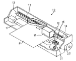
まず、構成を説明する。図1および図2において、インクジェット記録装置10は、3原色のカラー用インクおよびブラックインクを並列させたインクカートリッジ11をキャリッジ12にセットするようになっており、そのキャリッジ12は、ガイド13が主走査方向に案内しつつモータ14の駆動力がベルト15を介して伝達されて往復運動する。また、インクジェット記録装置10は、キャリッジ12下面の記録ヘッド(液体噴射装置)16に形成されている不図示のノズルからインクカートリッジ11内の各色のインク(液状流体)を吐出(噴射)させる。
【0023】
このインクジェット記録装置10は、キャリッジ12の移動する主走査方向に延在するプラテン17上に記録紙Pを給紙するとともに、印刷データに応じた各色インクを記録ヘッド16のノズルから選択的に吐出・噴射させることにより、その記録紙Pの記録面に文字などの画像を形成する。なお、この記録ヘッド16のインクの吐出方式は、限定されるものではなく、圧電(ピエゾ)素子の変位による加圧方式あるいはヒータの加熱気化による加圧方式のいずれを採用するものでも良い。
【0024】
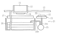
また、インクジェット記録装置10は、画像形成領域外の主走査方向片側外方(クリーニング動作位置)にヘッドクリーニング装置21を配置されている。ヘッドクリーニング装置21は、不図示の昇降手段により上昇されたときに記録ヘッド16下面のノズル形成面にキャップ22を押し当てて密閉空間を画成するキャップ機構23と、内装する可撓性チューブ24により流体の吸引・吐出動作を行うチューブポンプ25とを備えており、チューブポンプ25は、上流の吸引側(一端側)とする可撓性チューブ24aがキャップ機構23による密閉空間に接続される一方、下流の吐出側(他端側)とする可撓性チューブ24bが廃インクタンク26内に接続されている。
【0025】
そして、このヘッドクリーニング装置21は、快適な記録動作を繰り返すことを可能にするために、予め設定されているタイミングでキャップ機構23とチューブポンプ25とを動作させるようになっており、可撓性チューブ24内の流路24cを介してキャップ22により画成する密閉空間内を吸引して減圧することによって、記録ヘッド16のノズル内からインクを吸引して廃インクタンク26内に吐出するなどのヘッドクリーニングを行う。なお、キャップ22は、記録ヘッド16のノズル形成面に上縁を押し当てて密閉空間を画成するように四角の枠形状に形成されており、その底部にはシート状のスポンジ29を固着することにより記録ヘッド16のノズルから吸引するインクが飛散してしまうことを防止している。
【0026】
可撓性チューブ24は、図3に示すように、シリコンゴム等の可撓性材料を一体成形して2本のチューブ27、28を並列させるダブルのチューブ形状に作製されている。
【0027】
チューブポンプ25は、図4に示すように、上記の可撓性チューブ24と、有底の円筒形状に形成されて可撓性チューブ24の中間部分を内壁面31aに沿うように収容する収容ケース31と、この収容ケース31の内壁面31aに向かって可撓性チューブ24を押し潰すように押圧する押圧装置41とを組み立てるだけの簡易な構成に設計されている。
【0028】
収容ケース31には、内壁面31aの一部を切り欠いて可撓性チューブ24が出入り(引き出し/引き入れ)可能に開口する開口部32が形成されており、この開口部32の外方には可撓性チューブ24用の固定ブロック33を嵌合あるいはネジ止めするなどして取り付ける取付部34が形成されている。この固定ブロック33および取付部34は、収容ケース31の円筒軸方向(図中、A方向)と並行に延在するように形成された凹状溝部33aと凸状畝部34aとを嵌め合い係合させることにより、固定ブロック33の保持する可撓性チューブ24の中間部分を内壁面31aに沿わせた状態で収容ケース31内に位置決め固定することができる。
【0029】
また、収容ケース31は、開口部32に対応する位置の内側に、内壁面31aと同程度の高さの略三角柱形状に形成された補助部材101が立設されており、補助部材101は、大きく弾性変形可能な弾性材料により作製されている。この補助部材101は、図5に示すように、開口部32から出入りする可撓性チューブ24の内側の周面(内壁面から離隔する周面)に沿うように三角形状の2斜面101a、101bが湾曲面(平面でもよい)に形成されているとともにその斜面101a、101bの間の底面101cは内壁面31aの延長面と略平行になるように平面形状に形成されている。このため、補助部材101の底面101cは、収容ケース31内に出入りする可撓性チューブ24の内側周面に滑らかに連続する補助面となっている。
【0030】
ここで、固定ブロック33は、チューブ27、28を収容ケース31の円筒軸方向に並列させるように可撓性チューブ24を束ねており、流体の流通方向を転回させるように略U字形状(略円弧形状)に巻き返した状態で可撓性チューブ24を固定している。また、可撓性チューブ24は、収容ケース31内に収容されている場合には、図5に示すように、その内壁面31aに沿う状態で固定ブロック33から端部を延長させているので、その端部を振り分けたときにはΩ字形状となる。このため、収容ケース31は、円筒軸方向に可撓性チューブ24を重ねる必要がなく小型化することができる。なお、可撓性チューブ24は、チューブ27、28を一体成形しているが、これに限るものではなく、1本や3本以上としてもよく、また、一体成形することなく単に並列させたものとしてもよい。
【0031】
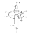
押圧装置41は、収容ケース31の底面31b中心の支軸孔31cに、回転円盤42の回転軸43が回転自在に軸支されており、その回転円盤42には、ローラ44を自由回転可能に軸支する支持部材51が収容ケース31内で略一体回転するように取り付けられている。この回転円盤42および支持部材51は、ローラ44を収容ケース31の内壁面31aの近傍に位置させるように軸支しており、回転円盤42は、回転軸43の端部に平面形状に形成された切欠き面43aに不図示のモータを係合されて回転駆動する。
【0032】
すなわち、この押圧装置41は、回転円盤42が軸心A(収容ケース31の円筒軸A)を中心に回転駆動することにより、収容ケース31の内壁面31aに沿うようにローラ44を回転移動させるようになっており、そのローラ44が収容ケース31の内壁面31aに向かって可撓性チューブ24を押し潰すように押圧しつつその押圧箇所を回転方向に移動する。
【0033】
これにより、チューブポンプ25は、キャップ機構23による密閉空間に接続した可撓性チューブ24a内を減圧して(負圧状態にして)記録ヘッド16のノズル内からインクを吸引する一方、廃インクタンク26に接続した可撓性チューブ24b内を加圧して吸引したインクを押し出して吐出する。
【0034】
詳細には、押圧装置41は、図6に示すように、回転円盤42と、ローラ44と、支持部材51と、コイルバネ61と、留め具62とを組み立てるだけの簡易な構成に設計されている。
【0035】
支持部材51は、互いに対面する上板52および下板53を連結体54で連結するように一体成形されている。上板52は、C字形状で表裏を貫通する案内溝55が形成されており、この案内溝55は、回転円盤42の軸心Aを中心とする略円周方向の半周にわたる円弧形状に形成されている。下板53には、上板52の案内溝55の内周面55aに対する円周方向の位置関係および形状の一致する外周面を有する小径部56が形成されており、この小径部56以外は大径に形成されている。
【0036】
この支持部材51の案内溝55の内周面55aおよび小径部56の外周面は、図6における矢印D1方向の始端部に位置する退避位置Tから終端部に位置する作動位置Sに進むほど、回転円盤42の軸心Aから径方向に徐々に離隔するように設定されている。
【0037】
そして、支持部材51は、上板52の案内溝55内にローラ44の一方の回転軸44bを保持・案内させるとともに下板53の小径部56の外周面にローラ44の他方の回転軸44c(図8、図10を参照)を案内させるようになっており、上板52および下板53の間にローラ44のローラ部44aを略円周方向に移動可能に挟持する。
【0038】
したがって、ローラ44は、ローラ部44aが回転円盤42の軸心Aに対して平行となる姿勢を維持しつつ自由回転可能に支持されるとともに、その軸心Aを中心とする略円周方向の一定の範囲内(図6の案内溝55における退避位置Tと作動位置Sの間)で径方向に移動することができ、その退避位置Tと作動位置Sとの間で往復回動することができる。
【0039】
すなわち、押圧装置41は、回転円盤42が図6における矢印D1方向と反対方向に回転駆動したときに、ローラ44が案内溝55の退避位置Tから作動位置Sに向かうように負荷を加えられて回転円盤42の軸心Aから径方向に徐々に離隔することになり、収容ケース31の内壁面31aに沿う可撓性チューブ24を押し潰す押圧力が増加するように設計されている。
【0040】
なお、この支持部材51は、上板52の案内溝55の外周面から径方向外方に延在する取付用溝55bが形成されており、この取付用溝55b内にローラ44の回転軸44bを差し込んで、容易に小径部56の外周面にローラ44の回転軸44cを沿わせることを可能にして組立作業を容易にしている。また、本実施形態では、ローラ44を1つのみの構成としているが、これに限るものではなく、2つ以上備えるようにしてもよいことはいうまでもない。
【0041】
また、支持部材51は、上板52、下板53および連結体54の中心に貫通孔51aが形成されるとともに、上板52および連結体54の案内溝55の反対側の一定範囲には下板53の近傍まで切り欠いた切欠き部51bが形成されている。貫通孔51aは、コイルバネ61の胴体部61a内に差し込んだ回転円盤42の回転軸43を挿通可能に形成されており、切欠き部51bは、回転円盤42の軸心Aと直交する断面形状がその軸心Aを中心する扇形状になるように形成されている。
【0042】
この切欠き部51bの案内溝55の終端部側(作動位置S側)の側面には、回転円盤42の軸心Aと平行に下板53側の底面から離隔する位置まで延在する凸状畝部57が形成されており、この凸状畝部57は、下板53側の底面との間に、回転円盤42の回転軸43が胴体部61a内に差し込まれたコイルバネ61の一方の腕部61bを係合・係止可能な凹状係止部57aを形成する。
【0043】
一方、回転円盤42は、支持部材51の切欠き部51内に位置させる突形状部46が下面42a(図7に図示)側に設けられており、この突形状部46は、図7に示すように、3つの第1〜第3ブロック46a〜46cを備えるように形成されている。
【0044】
第1ブロック46aは、回転円盤42の軸心Aを中心とする上板51と同等の厚さおよび径の扇形状に形成されており、その扇形状の内角(拡開角度)は支持部材51の切欠き部51bの断面形状よりも小さめに拡開する程度に設定されている。また、第2ブロック46bは、第1ブロック46aと同一の内角の扇形状に形成されているが、その扇形状としては支持部材51の連結体54と同等の径で、第1ブロック46aよりも厚めに形成されている。第3ブロック46cは、回転円盤42の軸心Aから離隔する第2ブロック46bの片側の角縁に立設されており、支持部材51の切欠き部51b内に位置したときに凸状畝部57から離隔する側で回転円盤42の軸心Aと平行に延在するように三角柱状に形成されている。
【0045】
このため、回転円盤42の突形状部46は、図7における第1〜第3ブロック46a〜46cの左側側面を平面形状のまま連続させることにより、支持部材51の切欠き部51b内の側面(凸状畝部57と反対側側面)に面接触して均等押圧可能に形成されている。また、この突形状部46の反対側の右側側面には、第2ブロック46bと第3ブロック46cとの間に段差部46dが形成されており、支持部材51の凹状係止部57aに腕部61bを係合・係止するコイルバネ61の他方の腕部61cをその段差部46dで受けるように組み立てられる。これにより、回転円盤42の回転軸43を胴体部61a内に挿通したコイルバネ61は、その弾性力により回転円盤42の突形状部46と支持部材51の凸状畝部57とを互いに離隔させる方向に付勢している。なお、本実施形態では、コイルバネ61を用いているが、これに限るものではなく、例えば、板バネやスプリングやゴムなどであってもよいことはいうまでもない。
【0046】
そして、留め具62は、小径の円盤形状に形成されて、回転円盤42の回転軸43を軸支する軸穴63が設けられており、この軸穴63には、回転軸43の切欠き面43aの反対側の切欠き面43bに係合する直線部63aが形成されている。このため、留め具62は、軸穴63が回転軸43に相対回転不能に係合して回転円盤42と一体回転するように連結される。
【0047】
また、この回転円盤42および留め具62には、円形の丸穴47a、67aと共に、この丸穴47a、67aを中心とする円周方向に広げた長穴47b、67bが貫通するように形成されており、支持部材51の上板52および下板53の図6における表裏の対称位置には、突起58a、58b(図6の上板52の表面側のみ図示)が形成されている。このため、回転円盤42および留め具62は、この丸穴47aおよび長穴47bに支持部材51の突起58a、58bを係合させることにより、その長穴47b、67bの範囲内での相対移動を許容しつつ支持部材51を略一体回転させることができる。
【0048】
次に、チューブポンプ25の組み立てを説明する。まず、図6に示すように、支持部材51およびローラ44を準備して、支持部材51の上板52の案内溝55の取付用溝55b内にローラ44の回転軸44bを差し込むことにより、その案内溝55の内周面55aと共に下板53の小径部56の外周面に回転軸44b、44cを沿わせてローラ44が自由回転かつ回動(円周方向への回転移動)可能に支持された状態に組み立てる。
【0049】
次いで、回転円盤42およびコイルバネ61を準備して、回転円盤42の回転軸43をコイルバネ61の胴体部61a内に挿通して、その回転軸43に外装された状態のコイルバネ61の腕部61cを突形状部46の第2、第3ブロック46b、46c間の段差部46dに係合させる。この後に、回転円盤42の回転軸43を支持部材51の貫通孔51a内に挿通して、その回転円盤42側のコイルバネ61の腕部61cを反対側の腕部61bに近接させつつ支持部材51の凸状畝部57により形成する凹状係止部57aにその腕部61bを係合・係止させる。同時に、回転円盤42の丸穴47aに支持部材51の突起58aを嵌合させるとともに、回転円盤42の長穴47bに支持部材51の突起58bを係合させて、回転円盤42および支持部材51を連結する。
【0050】
次いで、留め具62を準備して、支持部材51の下板53から突出する回転円盤42の回転軸43を留め具62の軸穴63内に嵌入してその切欠き面43bと直線部63aとを係合させる。同時に、回転円盤42と支持部材51との連結と同様に、丸穴67aに支持部材51の不図示の突起を嵌合させるとともに、長穴67bに支持部材51の不図示の突起を係合させることにより、留め具62を回転円盤42および支持部材51に連結して押圧装置41を組み立てる。
【0051】
ここで、組み立てられた押圧装置41は、回転円盤42と支持部材51とを相対回転させる力が加えられていないときには、図8に示すように、回転円盤42の突形状部46が、コイルバネ61の腕部61b、61cの互いに拡開しようとする弾性力により支持部材51の凸状畝部57から離間する方向に付勢され、その支持部材51の切欠き部51b側面を均等押圧する。このとき、支持部材51は、回転円盤42の丸穴47aに突起58aが嵌合しているので、図9に示すように、その突起58aを中心とする図9中の矢印方向にコイルバネ61の弾性力が加わっており、他の外部からの力が加えられていない場合には、突起58bが回転円盤42の長穴47b内の図9における右隅に位置している。
【0052】
一方、押圧装置41は、図10に示すように、コイルバネ61の弾性力に抗してその腕部61b、61c同士を近接させる方向の力が回転円盤42と支持部材51(ローラ44)に加えられると、回転円盤42の突形状部46と支持部材51の凸状畝部57が近接する。このとき、支持部材51は、回転円盤42の丸穴47aに突起58aが嵌合しているので、図11に示すように、その突起58aを中心とする図11中の矢印方向に回転円盤42に対して相対的に回動し、突起58bが回転円盤42の長穴47b内の図11における左隅に位置する。
【0053】
すなわち、押圧装置41は、ローラ44が支持部材51の案内溝55における作動位置S(図6参照)に位置するときに、力が加えられない場合には、そのローラ44は、図8に示すように、回転円盤42の軸心Aから最も離れた状態に位置することができる。また、押圧装置41は、同様に、ローラ44が作動位置Sに位置するときに、そのローラ44にコイルバネ61の弾性力に抗して支持部材51の突起58bを回転円盤42の長穴47b内で揺動させる力を加えられたときには、そのローラ44は、図10に示すように、回転円盤42の軸心Aに近い状態に位置することができる。
【0054】
このため、押圧装置41は、ローラ44に加えられる力に応じて支持部材51の突起58bが回転円盤42の長穴47bの範囲内程度に揺動することができ、ローラ44が加えられる力(反力)に応じて回転円盤42の軸心Aに近接・離隔することにより、後述するように、そのローラ44が可撓性チューブ24を収容ケース31の内壁面31a方向に押圧する力(押圧力)をコイルバネ61の弾性力で調整することができる。なお、この押圧装置41のローラ44は、作動位置Sから案内溝55の延長方向と反対方向の力を加えられたときには、支持部材51の案内溝55における退避位置T(図6参照)まで後退して回転円盤42の軸心Aに最も近い状態まで移動することができる。
【0055】
次いで、図4に示すように、収容ケース31の取付部34に形成されている凹状溝部33aと、可撓性チューブ24が固定されている固定ブロック33の凸状畝部34aとを嵌め合い係合させる。このとき、固定ブロック33の保持する可撓性チューブ24は、収容ケース31の開口部32の縁と補助部材101の斜面101a、101bとの間に差し込んで左右に振り分けることにより、その可撓性チューブ24の中間部分を収容ケース31の内壁面31aに沿わせた状態に準備する。
【0056】
この後に、押圧装置41を留め具62側から可撓性チューブ24内に押し込むようにして、回転円盤42の回転軸43の先端部を収容ケース31底面31bの支軸孔31cに回転自在に軸支させることにより、チューブポンプ25を組み立てる。このとき、押圧装置41のローラ44は、可撓性チューブ24の流路途中を、収容ケース31の内壁面31aに向かって軽く押し付ける程度で押圧する圧接状態になっている。
【0057】
次に、ヘッドクリーニング装置21による記録ヘッド16のクリーニング動作を説明する。まず、キャリッジ12がインクジェット記録装置10の画像形成領域外のクリーニング動作位置に移動すると、キャップ機構23のキャップ22が上昇して記録ヘッド16のノズル面に密着することにより密閉空間を画成する。この後に、押圧装置41が、回転円盤42の回転軸43に不図示のモータの駆動力を伝達されて、図12中に示す反時計回りの矢印D2方向(ローラ44を可撓性チューブ24の記録ヘッド16側から廃インクタンク26側に向かわせる正転動作方向)への回転を開始する。
【0058】
このとき、ローラ44は、可撓性チューブ24に圧接していることから、時計回りの摩擦力を加えられることになって、回転円盤42の案内溝55により案内されつつ可撓性チューブ24の相対回転に連れ回されて、その案内溝55の終端部の作動位置Sまで回転・回動(転動)する。
【0059】
この後には、ローラ44は、回転円盤42の案内溝55の終端部からさらに回動することを制限されていることから、その作動位置Sに位置しつつ時計回りに回転することになり、可撓性チューブ24の流路途中を収容ケース31の内壁面31aとの間で押し潰すように押圧しつつ、その押圧位置を図12中の矢印D2方向の正転動作(反時計回り)方向に移動する。このとき、ローラ44は、作動位置Sに位置して、圧接する可撓性チューブ24からの反力が大きくなる方向に変化した場合には、コイルバネ61の弾性力により吸収するように回転円盤42の軸心Aに近接する方向に揺動移動して安定した押圧力でその可撓性チューブ24を押圧することができる。
【0060】
このようにして、チューブポンプ25は、可撓性チューブ24内に体積変化を生じさせてローラ44の記録ヘッド16側(吸引上流側の可撓性チューブ24a)を減圧することにより、キャップ22の画成する密閉空間内を負圧にして記録ヘッド16のノズル内からインクや気泡を吸引する。このとき、チューブポンプ25は、同時に、ローラ44の廃インクタンク26側(吐出下流側の可撓性チューブ24b)内を加圧して記録ヘッド16のノズル内から吸引したインクや気泡を押し出すようにして廃インクタンク26内に吐出する。
【0061】
この正転動作中には、チューブポンプ25は、図13に示すように、開口部32近傍の可撓性チューブ24の束ねられている箇所を繰り返し通過することになる。
【0062】
このとき、ローラ44は、可撓性チューブ24の周面が回転円盤42の軸心Aから遠くなって、その可撓性チューブ24からの反力が小さくなった場合には、その反力の変化をコイルバネ61の弾性力により吸収するように回転円盤42の軸心Aから離隔する方向に揺動移動して効果的にその可撓性チューブ24を押圧する。
【0063】
また、同時に、収容ケース31には、開口部32から出入りする可撓性チューブ24の周面に、底面(補助面)101cを滑らかに連続させる補助部材101が設けられているので、ローラ44は、開口部32の近傍を通過する際には、下流側可撓性チューブ24bの周面からその補助部材101の底面101cに乗り上げた後に、その補助部材101の底面101cから上流側可撓性チューブ24aの周面に乗り換える。これにより、ローラ44は、可撓性チューブ24の周面の変化に追従移動して、反対側の上流側可撓性チューブ24aの周面に衝突するように急激に揺動してしまうことがなく、また、この補助部材101と共に収容ケース31内に出入りする可撓性チューブ24の上流側および下流側の双方を開口部32の両側の内壁面31aとの間で同時に押し潰して、その可撓性チューブ24内の減圧が開放されることを防止している。
【0064】
したがって、チューブポンプ25は、押圧装置41を正転動作方向に回転駆動させるときに、ローラ44が可撓性チューブ24に繰り返し衝突する衝突音を発生させることなく、ローラ44が収容ケース31内のどの位置を回動していても、常に可撓性チューブ24の流路途中を押し潰した状態を維持することができる。すなわち、このチューブポンプ25は、記録ヘッド16と廃インクタンク26との間の可撓性チューブ24内の減圧を開放することなく、静かにローラ44を繰り返し巡廻移動させて徐々にその可撓性チューブ24内の減圧を累積することができ、快適にヘッドクリーニング装置21によるクリーニング動作を実行することができる。
【0065】
なお、このヘッドクリーニング装置21は、このクリーニング動作を終了すると、図14に示すように、チューブポンプ25の押圧装置41を図14中に示す矢印D3方向(逆転動作方向)に回転駆動させて、ローラ44を回転円盤42の案内溝55により案内させつつ可撓性チューブ24との摩擦力により反時計回りに回転させてその始端部の退避位置Tまで回動させる。これにより、ローラ44は、この回転円盤42の軸心Aからも最も離隔する退避位置Tで可撓性チューブ24の押圧力を解放し、非クリーニング動作期間以外のときの加圧・変形などによって可撓性チューブ24や補助部材101が劣化等してしまうことを回避している。
【0066】
このように本実施形態においては、可撓性チューブ24を収容ケース31の内壁面31aに押圧して押し潰す押圧装置41のローラ44は、その可撓性チューブ24の出入りする収容ケース31の開口部42付近では、可撓性チューブ24の周面に滑らかに連続する補助部材101の底面(補助面)101に乗り上げて、可撓性チューブ24と補助部材101の双方を変形させつつ回転移動することができる。
【0067】
したがって、ローラ44は、収容ケース31の開口部32付近での可撓性チューブ24の周面の変化に急激かつ大きく追従移動して乗換先(上流側)の可撓性チューブ24に衝突することによる衝突音を繰り返し発生させることがなく、また、可撓性チューブ24内の減圧を維持しつつ、下流側から再度上流側の可撓性チューブ24へと繰り返し乗り換えて収容ケース31の開口部32を通過することができる。
【0068】
このことから、チューブポンプ25は、衝突音などの騒音を発生させずに、記録ヘッド16内のインクを効果的に吸引することができ、インクジェット記録装置10のクリーニング動作を効率よくかつ静かに行うことができる。
【0069】
次に、図15および図16は本発明に係るチューブポンプを搭載する液体噴射装置の第2実施形態であるインクジェット記録装置の一例を示す図である。なお、本実施形態は、上述実施形態と略同様に構成されているので、同様な構成には同一の符号を付して特徴部分を説明する(次の実施形態においても同様)。
【0070】
図15において、インクジェット記録装置10は、ヘッドクリーニング装置21のチューブポンプ25を構成する収容ケース31には、上述実施形態における補助部材101に代えて、補助部材111が設けられている。
【0071】
補助部材111は、その補助部材101と同様に、収容ケース31の内壁面31aと同程度の高さの略三角柱形状に形成されているが、その補助部材101とは異なって、大きく変形しない程度の硬さを有する弾性材料により作製されている。
【0072】
この補助部材111は、上述実施形態の補助部材101と略同様に、収容ケース31の開口部32から出入りする可撓性チューブ24の内側の周面に沿うように形成された三角形状の2斜面111a、111bと、その斜面111a、111bの間の底面101cとを備えている。
【0073】
すなわち、補助部材111は、2斜面111a、111bを平面に形成されるとともに、底面111cを収容ケース31の開口部32における内壁面31aの延長面と略平行な平面形状に形成されており、収容ケース31内にその開口部32から出入りさせる可撓性チューブ24の内側周面にその底面111cを補助面として滑らかに連続させている。なお、補助部材111の2斜面111a、111bは、上述実施形態のように湾曲面としてもよいが、後述する回動時の強度を確保するために平面形状としている。また、この補助部材111を備えるチューブポンプ25においても、上述実施形態と同様に組み立てることができる。
【0074】
そして、この補助部材111は、斜面111a、111bの間の頂部近傍を、収容ケース31の開口部32に対応する位置の内側に立設されている回動軸112に回動自在に軸支されている。
【0075】
このことから、チューブポンプ25の正転動作(ヘッドクリーニング装置21のクリーニング動作)中に、収容ケース31の開口部32に近接したときのローラ44は、図16に実線で示すように、当接した補助部材111を図中の時計回り方向に回動させて、下流側可撓性チューブ24bの周面に滑らかに連続するその底面111cに乗り上げる。この後に、収容ケース31の開口部32から離隔する方向にさらに移動して回動軸112を越えたときに、ローラ44は、補助部材111を図中の反時計回り方向に瞬間的に回動させて、滑らかに連続するその底面111cから上流側可撓性チューブ24aの周面に乗り換える。
【0076】
すなわち、補助部材111は、ローラ44により回動されることにより、そのローラ44が収容ケース31の内壁面31aに押し潰すように押圧する下流側の可撓性チューブ24を、斜面111bがそのまま開口部32の片側縁部の内壁面31aとの間で押し潰しつつ、ローラ44を底面111cに乗り上げさせる。
【0077】
そして、この補助部材111は、ローラ44が収容ケース31の開口部32から離隔する方向にさらに移動する際には、瞬間的に逆向きになるように回動して上流側の可撓性チューブ24を斜面111aと収容ケース31の開口部32の反対側縁部の内壁面31aとの間で押し潰しつつ、そのローラ44を再度上流側可撓性チューブ24に受け渡す。
【0078】
したがって、補助部材111は、ローラ44が収容ケース31の開口部32を通過する際に、可撓性チューブ24の押し潰しを解除する時間をできるだけ短くして、可撓性チューブ24内の減圧が開放されることを防止している。
【0079】
なお、このときに、ローラ44は、上述実施形態と同様に、補助部材111の底面111cに乗り上げて反対側の可撓性チューブ24に乗り換えるので、可撓性チューブ24の周面の変化に追従移動して、乗換先の可撓性チューブ24の周面に衝突するように急激に揺動することはない。また、補助部材111は、ローラ44が上流側可撓性チューブ24の周面に乗り換えた後には、可撓性チューブ24の弾性復帰力を上流側と下流側との双方から受けて中立の姿勢になるように回動復帰して、可撓性チューブ24の押し潰しを解除する。
【0080】
これにより、チューブポンプ25は、記録ヘッド16と廃インクタンク26との間の可撓性チューブ24内の減圧を開放することなく、静かにローラ44を繰り返し巡廻移動させて徐々にその可撓性チューブ24内の減圧を累積することができ、快適にヘッドクリーニング装置21によるクリーニング動作を実行することができる。
【0081】
このように本実施形態においては、上述実施形態と同様の作用効果を得て、チューブポンプ25はインクジェット記録装置10のクリーニング動作を効率よくかつ静かに行うことができる。これに加えて、補助部材111は、上述実施形態の補助部材101よりも硬いので、繰り返し弾性変形されることによる損傷を少なくすることができ、耐久性に優れる。
【0082】
次に、図17および図18は本発明に係るチューブポンプを搭載する液体噴射装置の第3実施形態であるインクジェット記録装置の一例を示す図である。
【0083】
図17において、インクジェット記録装置10は、ヘッドクリーニング装置21のチューブポンプ25を構成する収容ケース31には、上述実施形態における補助部材111に代えて、補助部材111が設けられている。
【0084】
補助部材121は、その補助部材111と同様に、収容ケース31の内壁面31aと同程度の高さの略三角柱形状に形成されて、大きく変形しない程度の硬さを有する弾性材料により形成されている。
【0085】
この補助部材121は、上述実施形態の補助部材111と略同様に、収容ケース31の開口部32から出入りする可撓性チューブ24の内側の周面に沿うように三角形状の2斜面121a、121bと、その斜面121a、121bの間の底面121cとを備えている。
【0086】
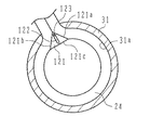
すなわち、補助部材121は、2斜面121a、121bを平面に形成されるとともに、底面121cを収容ケース31の開口部32における内壁面31aの延長面と略平行な平面形状に形成されており、収容ケース31内にその開口部32から出入りさせる可撓性チューブ24の内側周面にその底面121cを補助面として滑らかに連続させている。なお、補助部材121の2斜面121a、121bは、上述第1実施形態のように湾曲面としてもよいが、後述するスライド時の強度を確保するために平面形状としている。また、この補助部材121を備えるチューブポンプ25においても、上述実施形態と同様に組み立てることができる。
【0087】
そして、この補助部材121は、斜面121a、121bの間の頂部付近から底面121cに対する鉛直方向の近傍まで延在するスライド溝122が形成されており、収容ケース31の開口部32の対応する位置の内側に立設されているスライド軸123をそのスライド溝122内に位置させている。すなわち、補助部材121は、底面121cが収容ケース31の開口部32における内壁面31aの延長面と略平行になる姿勢を維持しつつ、その底面121cと共に斜面121a、121bを収容ケース31の開口部32に近接・離隔する方向にスライド可能に取り付けられている。なお、本実施形態では、補助部材121を一方向のみにスライドさせる場合を説明するが、上述実施形態の補助部材111と同様に回動可能に支持させてもよい。
【0088】
このことから、チューブポンプ25の正転動作(ヘッドクリーニング装置21のクリーニング動作)中に、収容ケース31の開口部32に近接したときのローラ44は、図18に実線で示すように、当接した補助部材121をその開口部32に近接させる方向にスライドさせて、下流側可撓性チューブ24bの周面に滑らかに連続するその底面121cに乗り上げる。この後に、ローラ44は、収容ケース31の開口部32から離隔する方向にさらに移動したときに、収容ケース31の開口部32に近接させたままの状態の補助部材121の底面121cから滑らかに連続する上流側可撓性チューブ24aの周面に乗り換える。
【0089】
すなわち、補助部材121は、ローラ44によりスライドされることにより、そのローラ44が収容ケース31の内壁面31aに押し潰すように押圧する可撓性チューブ24を、斜面121b、121cの双方がそのまま開口部32の両側縁部の内壁面31aとの間で押し潰しつつ、ローラ44を底面111cに乗り上げさせる。
【0090】
そして、この補助部材121は、ローラ44が収容ケース31の開口部32から離隔する方向にさらに移動する際には、斜面121b、121cの双方が開口部32の両側縁部の内壁面31aとの間で可撓性チューブ24を押し潰したまま、そのローラ44を再度上流側可撓性チューブ24に受け渡す。
【0091】
したがって、ローラ44が収容ケース31の開口部32を通過する際に、可撓性チューブ24の押し潰しを解除することがなく、可撓性チューブ24内の減圧が開放されることを防止している。
【0092】
なお、このときに、ローラ44は、上述実施形態と同様に、補助部材121の底面121cに乗り上げて反対側の可撓性チューブ24に乗り換えるので、可撓性チューブ24の周面の変化に追従移動して、乗換先の可撓性チューブ24の周面に衝突するように急激に揺動することはない。また、補助部材121は、ローラ44が上流側可撓性チューブ24の周面に乗り換えた後には、可撓性チューブ24の弾性復帰力を上流側と下流側との双方から受けて開口部32の近傍から離隔する位置まで後退復帰して、可撓性チューブ24の押し潰しを解除する。
【0093】
これにより、チューブポンプ25は、記録ヘッド16と廃インクタンク26との間の可撓性チューブ24内の減圧を開放することなく、静かにローラ44を繰り返し巡廻移動させて徐々にその可撓性チューブ24内の減圧を累積することができ、快適にヘッドクリーニング装置21によるクリーニング動作を実行することができる。
【0094】
このように本実施形態においては、上述実施形態と同様の作用効果を得て、チューブポンプ25はインクジェット記録装置10のクリーニング動作を効率よくかつ静かに行うことができ、また、補助部材121は上述実施形態の補助部材101よりも硬く耐久性に優れる。これに加えて、補助部材121は、ローラ44が収容ケース31の開口部32を通過する際には確実に可撓性チューブ24を押し潰す状態を維持することができ、その可撓性チューブ24内の減圧を累積させて快適にヘッドクリーニング装置21によるクリーニング動作を実行することができる。
【0095】
なお、上述実施形態においては、液体噴射装置を搭載するインクジェット記録装置の一例を説明するが、これに限るものではなく、例えば、液晶ディスプレイやELディスプレイなどを製造する電極材や色材の噴射装置などにも適用することもできる。
【0096】
【発明の効果】
本発明によれば、可撓性チューブを収容ケースの内壁面に押圧して押し潰す押圧部材は、その可撓性チューブの周面に滑らかに連続する補助部材の補助面に乗り上げて、可撓性チューブを出入りさせる開口部を通過することができ、急激に追従移動して乗換先の可撓性チューブとの衝突音を発生させてしまうことがなく、下流側から再度上流側へと繰り返し乗り換えることができる。
【0097】
この補助部材は、移動する押圧部材により弾性変形あるいは回動またはスライドさせて、可撓性チューブを押し潰すようにすることにより、押圧部材が可撓性チューブの出入りする開口部を通過する際に、可撓性チューブ内の負圧をできるだけ維持することができる。
【0098】
したがって、可撓性チューブ内の負圧を解放することなく、また、衝突音などの騒音を発生させずに、流体を効果的に吸引することができ、例えば、液体噴射装置では、ヘッド内の液体を効率よくかつ静かに吸引することができる。この結果、快適に動作することのできるチューブポンプおよび液体噴射装置を提供することができる。
【図面の簡単な説明】
【図1】本発明に係るチューブポンプを搭載する液体噴射装置の第1実施形態であるインクジェット記録装置の一例を示す図であり、その動作部を示す斜視図である。
【図2】その要部機構を示す概念立面図である。
【図3】その要部部品を示す斜視図である。
【図4】その要部構成を示す分解斜視図である。
【図5】その要部構成を示す一部断面平面図である。
【図6】その要部構成を示す分解斜視図である。
【図7】その要部部品を示す斜視図である。
【図8】その要部構成の機能を説明する立面状態図である。
【図9】その要部構成の機能を説明する平面状態図である。
【図10】その要部構成の機能を説明する立面状態図である。
【図11】その要部構成の機能を説明する平面状態図である。
【図12】その要部構成の動作を説明する一部切欠平面図である。
【図13】その要部構成の動作を説明する一部切欠平面図である。
【図14】その要部構成の動作を説明する一部切欠平面図である。
【図15】本発明に係るチューブポンプを搭載する液体噴射装置の第2実施形態であるインクジェット記録装置の一例を示す図であり、その要部構成を示す一部断面平面図である。
【図16】その要部構成の動作を説明する一部断面平面図である。
【図17】本発明に係るチューブポンプを搭載する液体噴射装置の第3実施形態であるインクジェット記録装置の一例を示す図であり、その要部構成を示す一部断面平面図である。
【図18】その要部構成の動作を説明する一部断面平面図である。
【図19】その従来技術を示す一部断面平面図である。
【図20】その従来技術を示す平面図である。
【図21】その改良技術を示す一部断面平面図である。
【符号の説明】
10 インクジェット記録装置
11 インクカートリッジ
16 記録ヘッド
21 ヘッドクリーニング装置
22 キャップ
24 可撓性チューブ
25 チューブポンプ
26 廃インクタンク
31 収容ケース
31a 内壁面
32 開口部
41 押圧装置
42 回転円盤
43 回転軸
44 ローラ
51 支持部材
55 案内溝
56 小径部
61 コイルバネ
101a、101b、111a、111b、121a、121b 斜面
101c、111c、121c 底面
101、111、121 補助部材
112 回動軸
122 スライド溝
123 スライド軸[0001]
BACKGROUND OF THE INVENTION
The present invention relates to a tube pump and a liquid ejecting apparatus, and more particularly to an apparatus that can operate silently.
[0002]
[Prior art]
Conventionally, a tube pump that generates a negative pressure in a tube and sucks fluid from one end side and discharges the fluid from the other end side is known. Since this tube pump has a simple and compact configuration, It is mounted on a wide variety of devices.
[0003]
For example, there is a tube pump mounted on an ink jet recording apparatus (liquid ejecting apparatus) that forms an image on recording paper by ejecting (jetting) ink (liquid fluid) from a nozzle of the recording head. It operates to suck ink from the nozzles at the timing of head cleaning for comfortable operation (see, for example,
[0004]
In the tube pumps described in
[0005]
[Patent Document 1]
JP 2001-301195 A [Patent Document 2]
Japanese Patent Laid-Open No. 7-253082
[Problems to be solved by the invention]
However, in both the tube pump described in Patent Document 1 (shown in FIG. 19) and the tube pump described in Patent Document 2 (shown in FIG. 20), the
[0007]
In addition, with the colorization of the ink jet recording apparatus, two
[0008]
In order to eliminate such inconvenience, as shown in FIG. 21, an opening 2b is provided in a part of the inner wall surface 2a of the
[0009]
However, in the tube pump that employs such a configuration, the
[0010]
In view of this, the present invention provides a quieter, moreover, by preventing the member that presses the peripheral surface of the flexible tube from rotating and moving stably, and preventing the flexible tube from being crushed. An object of the present invention is to provide a tube pump and a liquid ejecting apparatus that can be operated efficiently.
[0011]
[Means for Solving the Problems]
A first invention of a tube pump that solves the above problems includes a flexible tube having a fluid flow path defined therein, a housing case that houses the flexible tube along an inner wall surface, A pressing member that repeatedly moves from one end side to the other end side of the flexible tube while pressing so as to crush a part of the flexible tube toward the inner wall surface of the housing case. A tube pump that reduces the internal pressure on the upstream side by moving the pressing portion of the flexible tube, sucks the fluid into the flow path of the flexible tube from one end, and discharges the fluid from the other end. An opening that opens to the inner wall surface of the housing case so that the flexible tube can enter and exit, and an auxiliary that is provided in the vicinity of the opening of the housing case and smoothly continues to the peripheral surface that is separated from the inner wall surface of the flexible tube. An auxiliary member formed with a surface; A, it is characterized in that the passing on one end side pressing member assisting member passes through the vicinity of the opening of the accommodating case from the second end of the flexible tube.
[0012]
In this invention, the flexible tube storage case is not limited to a circular shape or an oval shape, but may have an inner wall surface that is smoothly continuous even if it is irregularly shaped. The number of openings is not limited to one, but may be two or more. In this case, when the pressing member moves in the direction of approaching the opening along the inner wall surface of the housing case, the pressing member presses the auxiliary surface of the auxiliary member smoothly continuing to the peripheral surface of the flexible tube. Get on the auxiliary surface. Then, when the pressing member further moves in the direction away from the opening of the housing case, the pressing member moves from the auxiliary surface of the auxiliary member smoothly continuing to the peripheral surface of the flexible tube to the peripheral surface of the flexible tube. Change to. Therefore, the pressing member can avoid abrupt following movement so as to collide with the peripheral surface of the flexible tube as the transfer destination when passing through the opening where the flexible tube enters and exits. The collision sound with a flexible tube etc. can be eliminated.
[0013]
According to a second invention of the tube pump for solving the above problem, in addition to the specific matter of the first invention, the auxiliary member is substantially the same as the extension surface inside the extension surface of the inner wall surface in the opening of the housing case. An auxiliary surface extending so as to be parallel to each other is formed, and the auxiliary surface is made of an elastic material that can be greatly elastically deformed.
[0014]
In this invention, a press member moves along the inner wall face of a storage case, and moves the press location which crushes a flexible tube. In the vicinity of the opening of the housing case, the pressing member smoothly runs on the auxiliary surface of the auxiliary member substantially parallel to the extended surface of the inner wall surface from the circumferential surface of the flexible tube to be crushed, and the auxiliary member is also elastically deformed. As it is, it is smoothly switched to the peripheral surface of the flexible tube on the opposite side. Therefore, the pressing member can smoothly transfer from the downstream side of the flexible tube to the upstream side again when passing through the opening where the flexible tube enters and exits. It does not cause a collision sound by suddenly following and moving so as to collide with.
[0015]
A third invention of a tube pump that solves the above-mentioned problems is that, in addition to the specific matters of the first invention, the auxiliary member is a pressing member that moves so as to approach the opening from the other end side of the flexible tube. The other end side of the flexible tube is rotated so as to be crushed when it comes into contact with the outer peripheral surface to form an auxiliary surface that is smoothly continuous with the peripheral surface of the other end, and a pressing member rides on the auxiliary surface. When the rotation axis is exceeded, the flexible tube rotates so as to crush one end of the flexible tube to form a smooth continuous auxiliary surface on the one end side peripheral surface, and when the pressing member is separated, the flexible tube It is characterized by being rotated and returned to release the crushing.
[0016]
In this invention, a press member moves along the inner wall face of a storage case, and moves the press location which crushes a flexible tube. When the pressing member moves in a direction close to the opening of the housing case, the pressing member rotates on the auxiliary member that comes into contact with the pressing member and runs smoothly on the auxiliary surface. When the pressing member tries to move further in the direction away from the opening of the housing case beyond the rotation axis of the auxiliary member, the auxiliary member is rotated in the opposite direction to smoothly continue from the auxiliary surface. Change to the circumference of the flexible tube. After this transfer, the auxiliary member returns to rotate so as to release the crushing of the flexible tube. Therefore, when the pressing member passes through the opening where the flexible tube enters and exits, the pressing member can be smoothed from the downstream side of the flexible tube to the upstream side only at the moment and by eliminating the crushing of the minute flexible tube. There is no possibility of suddenly following movement so as to collide with the peripheral surface of the flexible tube to which the transfer is made, and generating a collision sound.
[0017]
According to a fourth invention of the tube pump for solving the above problems, in addition to the specific matter of the first invention, the auxiliary member is in contact with a pressing member that moves so as to be close to the opening of the housing case. An auxiliary surface that smoothly moves on the peripheral surface of the flexible tube is formed so as to move close to the opening so as to crush one or both of the one end side and the other end side of the flexible tube. When separated, the flexible tube is moved away from the opening so as to release the crushing of the flexible tube and returned.
[0018]
In this invention, a press member moves along the inner wall face of a storage case, and moves the press location which crushes a flexible tube. When the pressing member moves in a direction close to the opening of the housing case, the pressing member moves close to the opening by moving the contacting auxiliary member close to the opening. The pressing member changes from the auxiliary surface to the peripheral surface of the flexible tube smoothly while maintaining the crushing of the flexible tube by the auxiliary member until the pressing member is separated from the opening of the housing case. After this transfer, the auxiliary member moves back in the direction to release the crushing of the flexible tube. Therefore, the pressing member smoothly changes from the downstream side of the flexible tube to the upstream side again without eliminating the crushing of the flexible tube when passing through the opening where the flexible tube enters and exits. It does not generate a collision sound by suddenly following and moving so as to collide with the peripheral surface of the flexible tube.
[0019]
An invention of a liquid ejecting apparatus that solves the above-described problem is a liquid ejecting apparatus that includes a head that ejects liquid and a cap that defines a sealed space together with the head, and the flexible tube of the tube pump includes the head and The liquid in the head is sucked by being connected to a sealed space by a cap.
[0020]
According to the present invention, the suction of the liquid in the head can be continued without releasing the negative pressure in the flexible tube and without repeating the collision sound. Therefore, the liquid in the head can be sucked efficiently and silently, and the mechanism incorporating the tube pump can be operated comfortably.
[0021]
DETAILED DESCRIPTION OF THE INVENTION
Hereinafter, the present invention will be described with reference to the drawings. 1 to 14 are views showing an example of an ink jet recording apparatus which is a first embodiment of a liquid ejecting apparatus equipped with a tube pump according to the present invention.
[0022]
First, the configuration will be described. 1 and 2, the ink
[0023]
The ink
[0024]
Further, in the
[0025]
The
[0026]
As shown in FIG. 3, the
[0027]
As shown in FIG. 4, the
[0028]
An
[0029]
Further, the
[0030]
Here, the fixed
[0031]
In the
[0032]
That is, the
[0033]
As a result, the
[0034]
Specifically, as shown in FIG. 6, the
[0035]
The
[0036]
As the inner
[0037]
The
[0038]
Accordingly, the
[0039]
That is, the
[0040]
The
[0041]
In addition, the
[0042]
On the side surface of the
[0043]
On the other hand, the
[0044]
The first block 46 a is formed in a fan shape having the same thickness and diameter as the
[0045]
For this reason, the protrusion-shaped
[0046]
The
[0047]
Further, the
[0048]
Next, the assembly of the
[0049]
Next, the
[0050]
Next, the
[0051]
Here, in the assembled pressing
[0052]
On the other hand, as shown in FIG. 10, the
[0053]
That is, when the
[0054]
For this reason, in the
[0055]
Next, as shown in FIG. 4, the concave groove portion 33 a formed in the
[0056]
Thereafter, the
[0057]
Next, the cleaning operation of the
[0058]
At this time, since the
[0059]
After this, since the
[0060]
In this way, the
[0061]
During this forward rotation operation, the
[0062]
At this time, when the peripheral surface of the
[0063]
At the same time, the
[0064]
Therefore, when the
[0065]
When this cleaning operation is completed, the
[0066]
As described above, in this embodiment, the
[0067]
Therefore, the
[0068]
Therefore, the
[0069]
Next, FIGS. 15 and 16 are views showing an example of an ink jet recording apparatus which is a second embodiment of a liquid ejecting apparatus equipped with a tube pump according to the present invention. In addition, since this embodiment is comprised in the substantially the same way as the above-mentioned embodiment, the same code | symbol is attached | subjected to the same structure and a characteristic part is demonstrated (same also in following embodiment).
[0070]
In FIG. 15, in the ink
[0071]
Like the
[0072]
The
[0073]
That is, the
[0074]
The
[0075]
Therefore, during the forward rotation operation of the tube pump 25 (the cleaning operation of the head cleaning device 21), the
[0076]
That is, the
[0077]
Then, when the
[0078]
Therefore, when the
[0079]
At this time, the
[0080]
As a result, the
[0081]
As described above, in the present embodiment, the same effect as the above-described embodiment can be obtained, and the
[0082]
Next, FIGS. 17 and 18 are views showing an example of an ink jet recording apparatus which is a third embodiment of a liquid ejecting apparatus equipped with a tube pump according to the present invention.
[0083]
In FIG. 17, in the ink
[0084]
Like the
[0085]
The
[0086]
That is, the
[0087]
The
[0088]
From this, during the forward rotation operation of the tube pump 25 (the cleaning operation of the head cleaning device 21), the
[0089]
That is, when the
[0090]
When the
[0091]
Therefore, when the
[0092]
At this time, the
[0093]
As a result, the
[0094]
As described above, in the present embodiment, the
[0095]
In the above-described embodiment, an example of an ink jet recording apparatus equipped with a liquid ejecting apparatus will be described. However, the present invention is not limited to this. For example, an ejecting apparatus for an electrode material or a color material for manufacturing a liquid crystal display, an EL display, or the like. It can also be applied to.
[0096]
【The invention's effect】
According to the present invention, the pressing member that presses and crushes the flexible tube against the inner wall surface of the housing case rides on the auxiliary surface of the auxiliary member smoothly continuing to the peripheral surface of the flexible tube, and is flexible. It can pass through the opening that allows the tube to enter and exit, and does not generate a collision sound with the flexible tube that is the destination of transfer by suddenly following movement, and repeatedly transfers from the downstream side to the upstream side again be able to.
[0097]
The auxiliary member is elastically deformed, rotated, or slid by the moving pressing member so as to crush the flexible tube, so that the pressing member passes through the opening / exiting portion of the flexible tube. The negative pressure in the flexible tube can be maintained as much as possible.
[0098]
Therefore, the fluid can be sucked effectively without releasing the negative pressure in the flexible tube and without generating a noise such as a collision sound. For example, in a liquid ejecting apparatus, The liquid can be sucked efficiently and gently. As a result, a tube pump and a liquid ejecting apparatus that can operate comfortably can be provided.
[Brief description of the drawings]
FIG. 1 is a diagram showing an example of an ink jet recording apparatus which is a first embodiment of a liquid ejecting apparatus equipped with a tube pump according to the present invention, and is a perspective view showing an operation part thereof.
FIG. 2 is a conceptual elevation view showing the principal part mechanism.
FIG. 3 is a perspective view showing the main components.
FIG. 4 is an exploded perspective view showing the configuration of the main part.
FIG. 5 is a partial cross-sectional plan view showing the configuration of the main part.
FIG. 6 is an exploded perspective view showing the configuration of the main part.
FIG. 7 is a perspective view showing the main parts.
FIG. 8 is an elevational state diagram for explaining the function of the main part configuration;
FIG. 9 is a plan view illustrating the function of the main part configuration.
FIG. 10 is an elevational state diagram for explaining the function of the main part configuration.
FIG. 11 is a plan view illustrating the function of the main part configuration.
FIG. 12 is a partially cutaway plan view for explaining the operation of the main configuration.
FIG. 13 is a partially cutaway plan view for explaining the operation of the main configuration.
FIG. 14 is a partially cutaway plan view for explaining the operation of the main configuration.
FIG. 15 is a diagram illustrating an example of an ink jet recording apparatus which is a second embodiment of a liquid ejecting apparatus equipped with a tube pump according to the present invention, and is a partial cross-sectional plan view illustrating a configuration of a main part thereof.
FIG. 16 is a partial cross-sectional plan view for explaining the operation of the main part configuration.
FIG. 17 is a diagram illustrating an example of an ink jet recording apparatus that is a third embodiment of a liquid ejecting apparatus equipped with a tube pump according to the present invention, and is a partial cross-sectional plan view illustrating a configuration of main parts thereof.
FIG. 18 is a partial cross-sectional plan view for explaining the operation of the main configuration.
FIG. 19 is a partial cross-sectional plan view showing the prior art.
FIG. 20 is a plan view showing the prior art.
FIG. 21 is a partial sectional plan view showing the improved technique.
[Explanation of symbols]
DESCRIPTION OF
Claims (6)
該可撓性チューブを内壁面に沿うように収容する収容ケースと、
該収容ケースの内壁面に向かって前記可撓性チューブの一部を押し潰すように押圧しつつ当該押圧箇所を該可撓性チューブの一端側から他端側に繰り返し巡廻移動する押圧部材と、
を備えて、
前記可撓性チューブの前記押圧箇所が移動することにより上流側内圧を減圧させて
前記可撓性チューブの流路内に流体を一端側から吸引して他端側から吐出させるチューブポンプであって、
前記可撓性チューブが出入り可能に前記収容ケースの内壁面に開口する開口部と、
前記収容ケースの該開口部近傍に設けられて前記可撓性チューブの内壁面から離隔する周面に沿って滑らかに連続する三角形状の2斜面からなる補助面が形成され前記開口部に対応する位置に立設されて回転軸に回転自在に軸支される補助部材と、
を有し、
該補助部材は前記収容ケースの開口部近傍を通過する前記押圧部材を前記可撓性チューブの他端側から一端側に受け渡される、
を特徴とするチューブポンプ。 A flexible tube bundled in an Ω-shape that defines a fluid flow path;
A housing case for housing the flexible tube along the inner wall surface;
A pressing member that repeatedly moves the pressing portion from one end side to the other end side of the flexible tube while pressing the inner casing toward the inner wall surface so as to crush a part of the flexible tube; ,
With
A tube pump that reduces the internal pressure on the upstream side by moving the pressing portion of the flexible tube, sucks fluid from one end side into the flow path of the flexible tube, and discharges the fluid from the other end side. ,
An opening that opens to the inner wall surface of the housing case so that the flexible tube can enter and exit;
Corresponding to the opening auxiliary surface made of triangular 2 slopes smoothly continuous along the circumferential surface of separating is formed from the inner wall surface of the flexible tube provided in the opening vicinity of the housing case An auxiliary member that is erected at a position and is rotatably supported on a rotation shaft;
Have
The auxiliary member is transferred to the one end of the pressing member which passes through the vicinity of the opening of the accommodating case from the other end of said flexible tube,
A tube pump characterized by
前記収容ケースの底面中心の支軸孔に対し回転軸により回転自在に軸支される回転円盤に構成された案内溝により支持され、
該案内溝は、
前記可撓性チューブの流路内に流体を一端側から吸引して他端側から吐出させる際に前記押圧部材が位置される作動位置と、
前記可撓性チューブに対する押圧力を解放させるように前記押圧部材が位置される待避位置と、
を備えることを特徴とする請求項1記載のチューブポンプ。The pressing member is
Supported by a guide groove configured in a rotating disk that is rotatably supported by a rotating shaft with respect to a supporting shaft hole at the bottom center of the housing case,
The guide groove is
An operating position where the pressing member is positioned when the fluid is sucked into the flow path of the flexible tube from one end side and discharged from the other end side;
A retracted position where the pressing member is positioned so as to release the pressing force on the flexible tube;
The tube pump according to claim 1, comprising:
前記収容ケースの開口部における内壁面の延長面よりも内側で該延長面と略平行となるように延在する補助面を形成されて、
大きく弾性変形可能な弾性材料により作製されていること、
を特徴とする請求項1または2に記載のチューブポンプ。The auxiliary member is
An auxiliary surface extending so as to be substantially parallel to the extended surface inside the extended surface of the inner wall surface in the opening of the housing case is formed,
Made of elastic material that can be elastically deformed greatly,
The tube pump according to claim 1, wherein:
前記可撓性チューブの他端側から前記開口部に近接するように移動する前記押圧部材に当接したときに該可撓性チューブの他端側を押し潰すように回動して当該他端側周面に滑らかに連続する補助面を形成し、
該補助面に前記押圧部材が乗り上げて回動軸を超えたときには可撓性チューブの一端側を押し潰すように回動して当該一端側周面に滑らかに連続する前記補助面を形成し、
前記押圧部材が離隔したときには前記可撓性チューブの押し潰しを解除するように回動して復帰すること、
を特徴とする請求項1または2に記載にチューブポンプ。The auxiliary member is
The other end of the flexible tube is rotated so as to crush the other end side of the flexible tube when it comes into contact with the pressing member moving so as to approach the opening from the other end side of the flexible tube. Form an auxiliary surface that is smoothly continuous on the side surface,
When the pressing member rides on the auxiliary surface and exceeds the rotation axis, the auxiliary surface is rotated so as to crush one end side of the flexible tube to form the auxiliary surface smoothly continuing to the peripheral surface of the one end side,
When the pressing member is separated, the flexible tube is rotated and returned to release the crushing of the flexible tube,
The tube pump according to claim 1 or 2, characterized in that.
前記収容ケースの前記開口部に近接するように移動する前記押圧部材に当接したときに前記可撓性チューブの一端側または他端側の一方または双方を押し潰すように該開口部に近接移動して当該可撓性チューブの周面に滑らかに連続する補助面を形成し、
前記押圧部材が離隔したときには前記可撓性チューブの押し潰しを解除するように前記開口部から離隔移動して復帰すること、
を特徴とする請求項1または2に記載にチューブポンプ。The auxiliary member is
Proximity movement to the opening so as to crush one or both of the one end side and the other end side of the flexible tube when contacting the pressing member moving so as to be close to the opening portion of the housing case Then, an auxiliary surface that smoothly continues on the peripheral surface of the flexible tube is formed,
When the pressing member is separated, the flexible tube is moved away from the opening so as to release the crushing and returned.
The tube pump according to claim 1 or 2, characterized in that.
該ヘッドと共に密閉空間を画成するキャップと、
を備える液体噴射装置であって、
前記請求項1乃至5のいずれか一項に記載の前記チューブポンプの前記可撓性チューブを前記ヘッドおよび前記キャップによる密閉空間に接続して、該ヘッド内の液体を吸引すること、
を特徴とする液体噴射装置。A head for ejecting liquid;
A cap that defines a sealed space with the head;
A liquid ejecting apparatus comprising:
Connecting the flexible tube of the tube pump according to any one of claims 1 to 5 to a sealed space by the head and the cap, and sucking the liquid in the head;
A liquid ejecting apparatus.
Priority Applications (4)
| Application Number | Priority Date | Filing Date | Title |
|---|---|---|---|
| JP2003101868A JP4288993B2 (en) | 2003-04-04 | 2003-04-04 | Tube pump and liquid injection device |
| US10/817,429 US7241119B2 (en) | 2003-04-04 | 2004-04-05 | Tube pump and liquid injection apparatus |
| US11/109,731 US7654803B2 (en) | 2003-04-04 | 2005-04-20 | Tube pump and liquid ejection apparatus |
| US12/507,176 US8147223B2 (en) | 2003-04-04 | 2009-07-22 | Tube pump and liquid ejection apparatus |
Applications Claiming Priority (1)
| Application Number | Priority Date | Filing Date | Title |
|---|---|---|---|
| JP2003101868A JP4288993B2 (en) | 2003-04-04 | 2003-04-04 | Tube pump and liquid injection device |
Related Child Applications (1)
| Application Number | Title | Priority Date | Filing Date |
|---|---|---|---|
| JP2009008481A Division JP4807416B2 (en) | 2009-01-19 | 2009-01-19 | Tube pump and liquid injection device |
Publications (2)
| Publication Number | Publication Date |
|---|---|
| JP2004308523A JP2004308523A (en) | 2004-11-04 |
| JP4288993B2 true JP4288993B2 (en) | 2009-07-01 |
Family
ID=33465520
Family Applications (1)
| Application Number | Title | Priority Date | Filing Date |
|---|---|---|---|
| JP2003101868A Expired - Fee Related JP4288993B2 (en) | 2003-04-04 | 2003-04-04 | Tube pump and liquid injection device |
Country Status (2)
| Country | Link |
|---|---|
| US (1) | US7241119B2 (en) |
| JP (1) | JP4288993B2 (en) |
Families Citing this family (20)
| Publication number | Priority date | Publication date | Assignee | Title |
|---|---|---|---|---|
| US7654803B2 (en) * | 2003-04-04 | 2010-02-02 | Seiko Epson Corporation | Tube pump and liquid ejection apparatus |
| JP4617707B2 (en) * | 2004-04-22 | 2011-01-26 | セイコーエプソン株式会社 | Tube pump and liquid injection device |
| FR2872554B1 (en) * | 2004-06-30 | 2008-09-19 | Millipore Corp | PERISTALTIC PUMP COMPRISING TUBE POSITIONING BODIES |
| JP4609266B2 (en) * | 2005-09-29 | 2011-01-12 | セイコーエプソン株式会社 | Tube pump and liquid injection device |
| JP2007205177A (en) * | 2006-01-31 | 2007-08-16 | Seiko Epson Corp | Tube pump and liquid jetting device |
| JP2007205176A (en) * | 2006-01-31 | 2007-08-16 | Seiko Epson Corp | Tube pump and liquid jetting device |
| JP2007205178A (en) * | 2006-01-31 | 2007-08-16 | Seiko Epson Corp | Tube pump and liquid jetting device |
| US20080056918A1 (en) * | 2006-08-31 | 2008-03-06 | Seiko Epson Corporation | Tube pump and liquid ejection apparatus |
| JP4131285B2 (en) * | 2006-08-31 | 2008-08-13 | セイコーエプソン株式会社 | Tube pump and liquid injection device |
| US8292604B2 (en) * | 2009-05-01 | 2012-10-23 | Xerox Corporation | Peristaltic pump |
| JP5155247B2 (en) * | 2009-05-12 | 2013-03-06 | ツカサ電工株式会社 | Tube pump |
| US11578716B2 (en) | 2010-01-22 | 2023-02-14 | Blue-White Industries, Ltd. | Overmolded tubing assembly and adapter for a positive displacement pump |
| US9909579B2 (en) | 2014-06-09 | 2018-03-06 | Blue-White Industries, Ltd. | Overmolded tubing assembly and adapter for a positive displacement pump |
| US20110180172A1 (en) * | 2010-01-22 | 2011-07-28 | Blu-White Industries, Inc. | High pressure, high flow rate tubing assembly for a positive displacement pump |
| JP5633179B2 (en) | 2010-04-30 | 2014-12-03 | ブラザー工業株式会社 | Cap device |
| US9777720B2 (en) | 2013-03-14 | 2017-10-03 | Blue-White Industries, Ltd. | High pressure, high flow rate tubing assembly and adapter for a positive displacement pump |
| JP6173108B2 (en) * | 2013-08-08 | 2017-08-02 | キヤノン株式会社 | Inkjet recording device |
| JP6300200B2 (en) * | 2014-04-18 | 2018-03-28 | パナソニックIpマネジメント株式会社 | Tube pump and fluid delivery method |
| JP6859692B2 (en) * | 2016-12-13 | 2021-04-14 | セイコーエプソン株式会社 | Liquid injection device |
| CN108839442B (en) * | 2018-07-27 | 2024-02-23 | 新会江裕信息产业有限公司 | Ink supply pump driving structure of ink-jet printer |
Family Cites Families (7)
| Publication number | Priority date | Publication date | Assignee | Title |
|---|---|---|---|---|
| US2899905A (en) * | 1959-08-18 | becher | ||
| US2102523A (en) * | 1936-03-23 | 1937-12-14 | Samuel J Ferrara | Blood transfusion machine |
| US2988001A (en) * | 1956-04-30 | 1961-06-13 | United Shoe Machinery Corp | Apparatus for use in the extractorporeal circulation of blood |
| US5340290A (en) * | 1992-12-21 | 1994-08-23 | Scilog, Inc. | Double feed peristaltic pump |
| JP3424697B2 (en) | 1994-03-14 | 2003-07-07 | セイコーエプソン株式会社 | Tube pump for inkjet recording device |
| US5630711A (en) * | 1995-09-08 | 1997-05-20 | Graymills Corporation | Peristaltic pump having a loop-shaped tube path |
| JP2001301195A (en) | 2000-04-21 | 2001-10-30 | Seiko Epson Corp | Ink jet recorder |
-
2003
- 2003-04-04 JP JP2003101868A patent/JP4288993B2/en not_active Expired - Fee Related
-
2004
- 2004-04-05 US US10/817,429 patent/US7241119B2/en active Active
Also Published As
| Publication number | Publication date |
|---|---|
| US7241119B2 (en) | 2007-07-10 |
| JP2004308523A (en) | 2004-11-04 |
| US20050030354A1 (en) | 2005-02-10 |
Similar Documents
| Publication | Publication Date | Title |
|---|---|---|
| JP4288993B2 (en) | Tube pump and liquid injection device | |
| JP3658287B2 (en) | Recovery unit and ink jet recording apparatus using the recovery unit | |
| US8529229B2 (en) | Ink jet printing apparatus | |
| JP3285074B2 (en) | Ink jet recording device | |
| JP4334687B2 (en) | Inkjet recording device | |
| JP4807416B2 (en) | Tube pump and liquid injection device | |
| JP2840409B2 (en) | Ink jet recording head and ink jet recording apparatus | |
| JP4062865B2 (en) | Tube pump and ink jet recording apparatus using the same | |
| JP3664213B2 (en) | Tube pump and ink jet recording apparatus using the same | |
| JP4315188B2 (en) | Liquid ejector | |
| JP2001193670A (en) | Tube pump and ink jet type recording device using the same | |
| JPH03101979A (en) | Carrying roller for ink-jet recording device | |
| JP4032336B2 (en) | Tube pump and ink jet recording apparatus using the same | |
| JP4780071B2 (en) | Tube pump and ink jet recording apparatus using the same | |
| JP2005240765A (en) | Tube pump and liquid jetting device | |
| JP4609266B2 (en) | Tube pump and liquid injection device | |
| JP2001304131A (en) | Tube pump and inkjet recording device using the same | |
| JP4285159B2 (en) | Tube pump and liquid injection device | |
| JP5252057B2 (en) | Tube pump and ink jet recording apparatus using the same | |
| JP5073422B2 (en) | Tube pump and image forming apparatus | |
| JP2000127450A (en) | Ink jet recorder | |
| JP4232805B2 (en) | Tube pump and liquid injection device | |
| JP4618272B2 (en) | Tube pump and ink jet recording apparatus using the same | |
| JPH068473A (en) | Device and method for ink suction for ink jet recording device | |
| JPH09131883A (en) | Ink-jet recording apparatus |
Legal Events
| Date | Code | Title | Description |
|---|---|---|---|
| A621 | Written request for application examination |
Free format text: JAPANESE INTERMEDIATE CODE: A621 Effective date: 20060302 |
|
| RD04 | Notification of resignation of power of attorney |
Free format text: JAPANESE INTERMEDIATE CODE: A7424 Effective date: 20070403 |
|
| A977 | Report on retrieval |
Free format text: JAPANESE INTERMEDIATE CODE: A971007 Effective date: 20080815 |
|
| A131 | Notification of reasons for refusal |
Free format text: JAPANESE INTERMEDIATE CODE: A131 Effective date: 20080902 |
|
| A521 | Written amendment |
Free format text: JAPANESE INTERMEDIATE CODE: A523 Effective date: 20081028 |
|
| A02 | Decision of refusal |
Free format text: JAPANESE INTERMEDIATE CODE: A02 Effective date: 20081125 |
|
| A521 | Written amendment |
Free format text: JAPANESE INTERMEDIATE CODE: A523 Effective date: 20090107 |
|
| A911 | Transfer to examiner for re-examination before appeal (zenchi) |
Free format text: JAPANESE INTERMEDIATE CODE: A911 Effective date: 20090126 |
|
| TRDD | Decision of grant or rejection written | ||
| A01 | Written decision to grant a patent or to grant a registration (utility model) |
Free format text: JAPANESE INTERMEDIATE CODE: A01 Effective date: 20090310 |
|
| A01 | Written decision to grant a patent or to grant a registration (utility model) |
Free format text: JAPANESE INTERMEDIATE CODE: A01 |
|
| A61 | First payment of annual fees (during grant procedure) |
Free format text: JAPANESE INTERMEDIATE CODE: A61 Effective date: 20090323 |
|
| R150 | Certificate of patent or registration of utility model |
Free format text: JAPANESE INTERMEDIATE CODE: R150 |
|
| FPAY | Renewal fee payment (event date is renewal date of database) |
Free format text: PAYMENT UNTIL: 20120410 Year of fee payment: 3 |
|
| FPAY | Renewal fee payment (event date is renewal date of database) |
Free format text: PAYMENT UNTIL: 20120410 Year of fee payment: 3 |
|
| FPAY | Renewal fee payment (event date is renewal date of database) |
Free format text: PAYMENT UNTIL: 20130410 Year of fee payment: 4 |
|
| FPAY | Renewal fee payment (event date is renewal date of database) |
Free format text: PAYMENT UNTIL: 20130410 Year of fee payment: 4 |
|
| FPAY | Renewal fee payment (event date is renewal date of database) |
Free format text: PAYMENT UNTIL: 20140410 Year of fee payment: 5 |
|
| S531 | Written request for registration of change of domicile |
Free format text: JAPANESE INTERMEDIATE CODE: R313531 |
|
| R350 | Written notification of registration of transfer |
Free format text: JAPANESE INTERMEDIATE CODE: R350 |
|
| LAPS | Cancellation because of no payment of annual fees |