JP4281862B2 - Banding material joining method and apparatus - Google Patents
Banding material joining method and apparatus Download PDFInfo
- Publication number
- JP4281862B2 JP4281862B2 JP2003063839A JP2003063839A JP4281862B2 JP 4281862 B2 JP4281862 B2 JP 4281862B2 JP 2003063839 A JP2003063839 A JP 2003063839A JP 2003063839 A JP2003063839 A JP 2003063839A JP 4281862 B2 JP4281862 B2 JP 4281862B2
- Authority
- JP
- Japan
- Prior art keywords
- conveyor
- cut
- take
- strip
- cut piece
- Prior art date
- Legal status (The legal status is an assumption and is not a legal conclusion. Google has not performed a legal analysis and makes no representation as to the accuracy of the status listed.)
- Expired - Fee Related
Links
Images


Description
【0001】
【発明の属する技術分野】
この発明は、帯状材料の継合わせ方法及びその装置に係わり、更に詳しくは補強コードをゴム被覆した細幅の帯状材料をタイヤ成形幅に対応する長さに切断し、この切断した帯状材料の切断片を、成形ドラムと直結する引取コンベヤ及び搬送コンベヤ上において非切断端縁部を順次継合わせてタイヤ一本分の長さに成形する帯状材料の継合わせ方法及びその装置に関するものである。
【0002】
【従来の技術】
従来、平行に配設した補強コードをゴム材料により被覆して成る長尺状の帯状材料を、搬送コンベヤ上で所定の長さに切断し、この切断片の非切断端縁を貼合わせ装置により互いに継ぎ合わせてタイヤ一本分の帯状材料を成形するタイヤ成形装置が知られている(例えば、特許文献1参照)。
【0003】
【特許文献1】
特開2000−141510号公報(第2〜3頁、図1)
【0004】
【発明が解決しようとする課題】
然しながら、このような従来の成形装置では、切断片の非切断端縁を互いに継ぎ合わせる場合に、切断片の継ぎ合わせ部の上下面から一対の継ぎ合わせローラを圧着させながら作業を行う必要があり、従ってこの貼合わせ装置を配置するためには搬送コンベヤを2分割する必要があった。
【0005】
しかし、搬送コンベヤを2分割すると、この分割したコンベヤ間の部分に隙間が発生し、この隙間に長手方向に剛性を持たない切断片の非切断端縁が脱落し、非切断端縁の貼合わせにトラブルを生じたり、帯状材料の継合わせを自動化させることが難しいと言う問題があった。
【0006】
この発明はかかる従来の問題点に着目し、帯状材料から所定の長さに切断した切断片を搬送コンベヤと引取コンベヤとの接続部において確実に継合わせを行うことが出来、成形サイクルに同期して、成形ドラムに供給する帯状材料の継合わせを自動化させることが出来る帯状材料の継合わせ方法及びその装置を提供することを目的とするものである。
【0007】
【課題を解決するための手段】
この発明は上記目的を達成するため、この発明の帯状材料の継合わせ方法は、帯状材料の供給手段から送り出された帯状材料を送りコンベヤ上においてタイヤ成形幅に対応する長さに切断し、この切断した帯状材料の切断片を、搬送手段を介して成形ドラムと直結する引取コンベヤ及び搬送コンベヤ上の所定位置に移載させながら非切断端縁部を順次貼合わせてタイヤ一本分の長さに成形する帯状材料の継合わせ方法であって、最初に切断した帯状材料の切断片を、搬送手段を介して成形ドラムと直結する引取コンベヤ上の所定位置に移載させた後、この引取コンベヤを逆転駆動させて切断片の非切断端縁部を貼合わせ位置まで後退させ、次に切断した帯状材料の第2の切断片を搬送手段を介して搬送コンベヤ上の所定位置に移載させ、この搬送コンベヤを正転駆動させて第2の切断片の非切断端縁部を貼合わせ位置まで搬送し、最初に切断した切断片と第2の切断片との非切断端縁部を貼合わせ装置により継合わせ、第3番目以降の切断片は、前記継合わせた帯状材料を引取コンベヤにより成形ドラム側に所定距離搬送すると共に、第2切断片と同様に搬送手段を介して切断片を搬送コンベヤ上の所定位置に順次移載させ、前記貼合わせ装置により切断片の非切断端縁部同士を順次継合わせてタイヤ一本分の長さまで成形することを要旨とするものである。
【0008】
ここで、前記帯状材料とは、平行に配設した補強コードの表裏面にゴム材料を被覆したタイヤカーカス材等を使用するものである。
【0009】
このように、最初に切断した帯状材料の切断片の非切断端縁を貼合わせ位置まで後退させ、次に切断した帯状材料の非切断端縁と突き合わせて貼合わせ装置により継合わせることで、搬送コンベヤと引取コンベヤとの隙間に切断片の非切断端縁が脱落することなく、切断した切断片を搬送コンベヤと引取コンベヤとの接続部において確実に継合わせを行うことが出来るため、継合わせ工程におけるトラブルを回避させることが出来、帯状材料の継合わせを自動化させることが可能である。
【0010】
また、この発明の帯状材料の継合わせ装置は、平行に配設した補強コードの表裏面にゴム材料を被覆した帯状材料の供給手段とタイヤ成形ドラムとの間に、前記帯状材料を所定の長さに切断する切断装置を備えた送りコンベヤと、この送りコンベヤの搬送方向と直交する向きに、搬送コンベヤと成形ドラムに直結する正転または逆転可能な引取コンベヤとを直列に配設し、搬送コンベヤと引取コンベヤとの接続部に、帯状材料の切断片の非切断端縁部を継合わせるための貼合わせ装置を設置し、前記送りコンベヤと搬送コンベヤとの間、及び送りコンベヤと引取コンベヤとの間に、切断した帯状材料の切断片を吸着保持して移載させる搬送手段をそれぞれ設置したことを要旨とするものである。
【0011】
ここで、前記貼合わせ装置としては、搬送コンベヤと引取コンベヤとの接続部に帯状材料の搬送方向と直交する向きに往復移動する上下一対の回転自在な引き寄せローラにより構成したものである。
【0012】
このように、送りコンベヤと直交する向きに、搬送コンベヤと成形ドラムに直結する正転または逆転可能な引取コンベヤとを直列に配設し、更に搬送コンベヤと引取コンベヤとの接続部に、帯状材料の切断片の非切断端縁部を継合わせるための貼合わせ装置を設置し、前記送りコンベヤと搬送コンベヤとの間、及び送りコンベヤと引取コンベヤとの間に、切断した帯状材料の切断片を吸着保持して移載させる搬送手段をそれぞれ設置した構成により、切断した切断片の非切断端縁部を搬送コンベヤと引取コンベヤとの接続部において確実に継合わせを行うことが出来、成形サイクルに同期して、簡素で安価な機構により帯状材料の継合わせを自動化させることが出来るものである。
【0013】
【発明の実施の形態】
以下、添付図面に基づき、この発明の実施形態を説明する。
【0014】
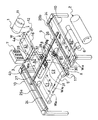
図1は、この発明にかかる帯状材料の継合わせ方法を実施するための継合わせ装置全体の概略構成図を示し、この継合わせ装置は、帯状材料Wの供給手段1とタイヤの成形ドラム2との間に、前記帯状材料Wを所定の長さに切断する切断装置3を備えたエンドレス状のベルトから構成される送りコンベヤ4a,4bと、この送りコンベヤ4a,4bの搬送方向と直交する向きにエンドレス状のベルトから構成される搬送コンベヤ5と、成形ドラム2に直結する正転または逆転可能なエンドレス状のベルトから構成される引取コンベヤ6とを直列に配設し、これらの送りコンベヤ4a,4b、搬送コンベヤ5、引取コンベヤ6は、制御装置7からの信号に基づき図示しないパルスモータの回転駆動により搬送速度や正転または逆転駆動が制御されるようになっている。
【0015】
また、搬送コンベヤ5と引取コンベヤ6との接続部Xには、帯状材料Wの切断片Waの非切断端縁部Wx1 ,Wx2 を継合わせるための貼合わせ装置8が設置してあり、更に、前記送りコンベヤ4bと搬送コンベヤ5との間、及び送りコンベヤ4bと引取コンベヤ6との間には、切断した帯状材料Wの切断片Waを切断状態の向きで吸着保持し、送りコンベヤ4b上から引取コンベヤ6及び搬送コンベヤ5上の所定位置に移載させる二軸組合せ用の搬送手段9が支持フレーム10を介して設置されている。
【0016】
前記供給手段1の巻出しロール11から巻出される帯状材料Wとしては、この実施形態では、平行に配設した図示しない補強コードの表裏面にゴム材料を被覆した長尺状のタイヤ用のカーカス材料であるが、他の帯状材料を使用することも可能であり、巻出しロール11に巻付けられている帯状材料Wは、フェスツーナ等の張力調整装置12を介して帯状材料Wが前記送りコンベヤ4a上に所定の張力を保持した状態で送り出されるように構成されている。
【0017】
前記送りコンベヤ4a,4b間に設置される切断装置3は、図2〜図4に示すように、モータ13により回転駆動される丸刃14が送りコンベヤ4a,4b間の幅方向に設置された切断ガイド15に沿って走行し、送りコンベヤ4a上を搬送されて来た帯状材料Wを押え手段16により押さえた状態で所定の長さに切断するものである。
【0018】
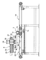
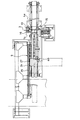
次に、前記搬送コンベヤ5と引取コンベヤ6との接続部Xに設置した貼合わせ装置8は、図1及び図5,図6に示すように、搬送方向と直交する向きにガイド部材17に沿って往復移動する上下一対の回転自在な2個の引き寄せローラ18a,18bと、切断片Waの非切断端縁部Wx1 ,Wx2 の近傍を押さえる押さえ装置19a,19bとにより構成され、上下一対の引き寄せローラ18a,18bは、円錐台状に形成されて非切断端縁部Wx1 ,Wx2 の継合わせ中心に向かって傾斜して取付けられている。
【0019】
この上下一対の引き寄せローラ18a,18bは、シリンダー等の昇降装置20により昇降し、切断片Waの非切断端縁部Wx1 ,Wx2 を上下から挟み込んで互いに圧着させながらガイド部材17に沿って走行するもので、ガイド部材17の下方には、引き寄せローラ18a,18bをガイドレール17aに沿って走行させるための駆動モータM及び駆動チェーンSから成る駆動手段21が設けられている。
【0020】
また前記押さえ装置19a,19bは、支持ブラケット22に鉛直向きに取付けられた押さえシリンダー23a,23bのロッドの先端に取付けられ、前後の非切断端縁部Wx1 ,Wx2 の近傍をガイド部材17上に押し付けて固定し、この状態で前記引き寄せローラ18a,18bにより非切断端縁部Wx1 ,Wx2 を引き寄せながら貼合わせて圧着させるものである。
【0021】
また、前記送りコンベヤ4bと搬送コンベヤ5との間に設置された二軸組合せ用の搬送手段9は、送りコンベヤ4a,4bと平行に立設された支持フレーム10にガイドレール24を備えたガイドフレーム25a,25bが取付けられ、このガイドフレーム25a,25bのガイドレール24には、送りコンベヤ4a,4bの搬送方向と平行に往復移動する走行フレーム26が架設されている。
【0022】
この走行フレーム26は、前記ガイドフレーム25a,25bに組み込まれた図示しないロッドレスシリンダーにより往復移動し、また走行フレーム26に敷設されたガイドレール27には、バキューム手段28が図示しないロッドレスシリンダーを介して移動可能に吊設されている。
【0023】
このバキューム手段28は、前記走行フレーム26のガイドレール27に昇降シリンダー29を介して支持プレート30が水平に吊設され、この支持プレート30の底面の数箇所には、シリンダー31を介して昇降するバキュームパッド32が取付けられている。
【0024】
従って、上記バキューム手段28は、走行フレーム26により送りコンベヤ4a,4bの搬送方向と平行に移動可能で、かつ走行フレーム26のガイドレール27に沿って引取コンベヤ6及び搬送コンベヤ5の搬送方向と平行に移動することが可能であり、前記切断装置3により定尺切断された切断片Waを送りコンベヤ4b上から吸着保持して、引取コンベヤ6及び搬送コンベヤ5の所定位置まで搬送して移載させることが可能である。
【0025】
次に、上記のような構成から成る帯状材料Wの継合わせ装置による継合わせ方法を、図1及び図9を参照しながらについて説明する。
【0026】
帯状材料Wの継合わせ装置による継合わせ方法の第1実施形態としては、最初に切断された帯状材料Wの切断片Waの搬送経路を変えたもので、この実施形態では、最初に切断された帯状材料Wの切断片Waは、送りコンベヤ4b上のA2の位置から図9の(1) に待機する二軸組合せ用の搬送手段9のバキューム手段28が下降してバキュームパッド32により吸着保持すると共に上昇し、この状態で走行フレーム26は、その位置で停止し、搬送手段9のバキューム手段28が走行フレーム26のガイドレール27に沿って引取コンベヤ6の移載位置ラインY−Y上の図9の(4) の位置まで移動する。
【0027】
次いで、走行フレーム26は、ガイドフレーム25a,25bに沿って引取コンベヤ6のセンター位置Z−Zにおける貼合わせ装置8の近傍位置、即ち、図9の(3) 位置まで移動して、バキュームパッド32により吸着保持されていた最初に切断された帯状材料Wの切断片Waを引取コンベヤ6のB1位置の図9の(3) に移載する。
【0028】
引取コンベヤ6の図9の(3) 位置に切断片Waが移載され、切断片Waを開放すると、引取コンベヤ6は制御装置7からの出力信号によりパルスモータを介して逆転駆動し、切断片Waの非切断端縁部Wx1 を搬送コンベヤ5と引取コンベヤ6との接続部Xにおける貼合わせ位置まで後退移動させる。
【0029】
次に、切断片Waを開放した搬送手段9のバキューム手段28は、走行フレーム26がガイドフレーム25a,25bに沿って引取コンベヤ6の移載位置ラインY−Y上の図9の(4) の位置まで後退移動した後、走行フレーム26のガイドレール27に沿って送りコンベヤ4b上の図9の(1) に待機位置に戻る。
【0030】
そして、帯状材料Wから切断された第2の切断片Waについては、上記第1実施形態と同様に、送りコンベヤ4bから図9の(1) に待機する二軸組合せ用の搬送手段9のバキューム手段28が下降してバキュームパッド32により吸着保持すると共に上昇し、この状態で走行フレーム26は、ガイドフレーム25a,25bに沿って引取コンベヤ6及び搬送コンベヤ5のセンター位置Z−Zの(2) の位置まで移動し、バキュームパッド32により吸着保持されていた第2の切断片Waをそのままの向きで搬送コンベヤ5のセンター位置Z−Zに載置させる。
【0031】
第2の切断片Waが搬送コンベヤ5のセンター位置Z−Zの(2) 位置に移載されると、搬送コンベヤ5は制御装置7からの出力信号によりパルスモータを介して正転駆動により、切断片Waの非切断端縁部Wxを搬送コンベヤ5のC2上、即ち、引取コンベヤ6との接続部Xにおける貼合わせ位置まで移動させる。
【0032】
そして、最初に切断した切断片Waの非切断端縁部Wx1 と、第2の切断片Waの非切断端縁部Wx2 とが接続部Xにおいて突き合わされた後、貼合わせ装置8の上下一対の回転自在な2個の引き寄せローラ18a,18bにより非切断端縁部Wx1 ,Wx2 を引き寄せながら貼合わせて圧着させるものである。
【0033】
このようにして、最初に切断した切断片Waの非切断端縁部Wx1 と、第2の切断片Waの非切断端縁部Wx2 とが貼合わされたら、引取コンベヤ6をパルスモータを介して正転駆動し、第2の切断片Waの先ほど接続した非切断端縁部Wx2 と反対側の非切断端縁部Wx1 の端末部が搬送コンベヤ5と引取コンベヤ6との接続部Xにおける貼合わせ位置まで移動させる。
【0034】
そして、第3以降の切断片Waは、上記第1実施形態と同様の操作により順次搬送させて継合わせることでタイヤ一本分の長さまで成形し、その後は引取コンベヤ6のB2位置からタイヤ成形ドラム2上に供給してタイヤの成形を行うものである。
【0035】
このように、送りコンベヤ4a,4bと直交する向きに、搬送コンベヤ5とタイヤ成形ドラム2に直結する正転または逆転可能な引取コンベヤ6とを直列に配設し、更に搬送コンベヤ5と引取コンベヤ6との接続部Xに、帯状材料Wの切断片Waの非切断端縁部Wx1,Wx2 を継合わせるための貼合わせ装置8を設置し、更に前記送りコンベヤ4bと搬送コンベヤ5との間、及び送りコンベヤ4bと引取コンベヤ6との間に、切断した帯状材料Wの切断片Waを吸着保持して移載させる搬送手段9,10をそれぞれ設置した構成により、切断した切断片Waの非切断端縁部Wx1,Wx2 を搬送コンベヤ5と引取コンベヤ6との接続部Xにおいて確実に継合わせを行うことが出来るものである。
【0036】
次に、帯状材料Wの継合わせ装置による継合わせ方法の第2実施形態としては、先ず供給手段1の巻出しロール11から巻出された帯状材料Wの幅は、タイヤ一本分の長さ(成形ドラム2の周長)の1/nの幅に切断されたものであり、この帯状材料Wをn枚接続させることによりタイヤ一本の長さに形成するものである。
【0037】
即ち、巻出しロール11から巻出された帯状材料Wは、図1に示す張力調整装置12を介して送りコンベヤ4aのA1上に送り出され、送りコンベヤ4a,4bの回転駆動により送りコンベヤ4b上に1回でタイヤ成形幅Hだけ乗るように搬送され、その後に切断する。
【0038】
切断位置から切断幅(タイヤ成形幅H)分だけ出た帯状材料Wは、押え手段16により切断時に帯状材料Wが移動しないように押えられた状態で、切断装置3によりタイヤ成形幅Hの長さに切断される。切断された帯状材料Wの切断片Waは、送りコンベヤ4bによってA2上の所定位置まで搬送される。
【0039】
そして、最初に切断された帯状材料Wの切断片Waは、図1における送りコンベヤ4b上のA2の位置から図9の(1) に待機する二軸組合せ用の搬送手段9のバキューム手段28が下降し、バキュームパッド32により吸着保持すると共に上昇し、この状態で走行フレーム26は、ガイドフレーム25a,25bに沿って引取コンベヤ6及び搬送コンベヤ5のセンター位置Z−Zの(2) の位置まで移動し、バキュームパッド32により吸着保持されていた切断片Waをそのままの向きで搬送コンベヤ5のセンター位置Z−Zに載置させる。
【0040】
なお、この実施形態は、継合わせ方法において、最初に切断した切断片Waの非切断端縁部Wx1 と、第2の切断片Waの非切断端縁部Wx2 とが逆になり、最初に切断した切断片Waの非切断端縁部Wx2 、第2の切断片Waの非切断端縁部Wx1 となる。
【0041】
次に、上記と同様にして帯状材料Wから切断された第2の切断片Waは、前記搬送コンベヤ5のセンター位置Z−Zから図9の(1) に戻った搬送手段9のバキューム手段28が送りコンベヤ4bからバキューム手段28が下降してバキュームパッド32により吸着保持され、バキューム手段28が上昇後、走行フレーム26のガイドレール27に沿って図9の(4) の位置まで移動し、走行フレーム26は引取コンベヤ6の貼合わせ装置8の近傍位置、即ち、図9の(3) 位置まで移動して図1に示す引取コンベヤ6のB1位置に第2の切断片Waを移載する。
【0042】
引取コンベヤ6の(3) 位置に切断片Waが移載されると、引取コンベヤ6は制御装置7からの出力信号によりパルスモータを介して逆転駆動し、切断片Waの非切断端縁部Wx2 を搬送コンベヤ5と引取コンベヤ6との接続部Xにおける貼合わせ位置まで後退移動させる。
【0043】
この状態で、搬送コンベヤ5は制御装置7からの出力信号によりパルスモータを介して正転駆動により、最初の切断片Waの非切断端縁部Wx1 を搬送コンベヤ5のC2上、即ち、引取コンベヤ6との接続部Xにおける貼合わせ位置まで移動させる。そして、最初に切断した切断片Waの非切断端縁部Wx1 と、第2の切断片Waの非切断端縁部Wx2 とが接続部Xにおいて突き合わされた後、切断片Waの非切断端縁部Wx1 ,Wx2 の近傍をそれぞれ押さえ装置19a,19bにより動かないように押圧する。
【0044】
このような状態から貼合わせ装置8の上下一対の回転自在な2個の引き寄せローラ18a,18bが搬送方向と直交する向きに配設されたガイド部材17に沿って移動すると共に、上下一対の回転自在な2個の引き寄せローラ18a,18bにより非切断端縁部Wx1 ,Wx2 を引き寄せながら貼合わせて圧着させる。
【0045】
このようにして、最初に切断した切断片Waの非切断端縁部Wx1 と、第2の切断片Waの非切断端縁部Wx2 とが貼合わされ、継合わされら、引取コンベヤ6をパルスモータを介して正転駆動し、第2の切断片Waの非切断端縁部Wx2 の端末部が搬送コンベヤ5と引取コンベヤ6との接続部Xにおける貼合わせ位置まで移動させる。
【0046】
そして第3番目以降の切断片Waは、第1の切断片Waと同様に、送りコンベヤ4bのA2の(1) 位置から二軸組合せ用の搬送手段9のバキューム手段28が下降してバキュームパッド32により吸着保持すると共に上昇し、この状態で走行フレーム26は、ガイドフレーム25a,25bに沿って引取コンベヤ6及び搬送コンベヤ5のセンター位置Z−Zの(2) の位置まで移動し、バキュームパッド32により吸着保持されていた第3の切断片Waをそのままの向きで搬送コンベヤ5のセンター位置Z−Zに載置させ、更に搬送コンベヤ5を正転駆動させて第3の切断片Waの非切断端縁部Wx2 の端末部が搬送コンベヤ5と引取コンベヤ6との接続部Xにおける貼合わせ位置まで移動させる。
【0047】
この後は、上記と同様に貼合わせ装置8により最初の切断片Waの非切断端縁部Wx1 と第3の切断片Waの非切断端縁部Wx2 の端末部とが貼合わされる。
【0048】
このような操作を繰返し行い、切断片Waの非切断端縁部Wx1 ,Wx2 を順次継合わせてタイヤ一本分の長さまで成形した後は、引取コンベヤ6のB2位置からタイヤ成形ドラム2上に供給してタイヤの成形を行うものである。
【0049】
以上のように、供給手段1の巻出しロール11から巻出されたタイヤ一本分の長さ(成形ドラム2の周長)の1/nの幅に形成された帯状材料Wをタイヤ成形幅Hに切断し、この帯状材料Wをn枚接続させることによりタイヤ一本の長さに形成するもので、切断枚数n枚は、タイヤユニフォミティーを考慮した場合、素数枚切断して継合わせるのが好ましい。
【0050】
【発明の効果】
この発明は、上記のように最初に切断した帯状材料の切断片を、搬送手段を介して成形ドラムと直結する引取コンベヤ上の所定位置に移載させた後、この引取コンベヤを逆転駆動させて切断片の非切断端縁部を貼合わせ位置まで後退させ、次に切断した帯状材料の第2の切断片を搬送手段を介して搬送コンベヤ上の所定位置に移載させ、この搬送コンベヤを正転駆動させて第2の切断片の非切断端縁部を貼合わせ位置まで搬送し、最初に切断した切断片と第2の切断片との非切断端縁部を貼合わせ装置により継合わせ、第3番目以降の切断片は、前記継合わせた帯状材料を引取コンベヤにより成形ドラム側に所定距離搬送すると共に、第2切断片と同様に搬送手段を介して切断片を搬送コンベヤ上の所定位置に順次移載させ、前記貼合わせ装置により切断片の非切断端縁部同士を順次継合わせてタイヤ一本分の長さまで成形するので、搬送コンベヤと引取コンベヤとの隙間に切断片の非切断端縁が脱落することなく、切断した切断片を搬送コンベヤと引取コンベヤとの接続部において確実に継合わせを行うことが出来、帯状材料の継合わせを自動化させることが出来る。
【0051】
また、この発明の帯状材料の継合わせ装置は、平行に配設した補強コードの表裏面にゴム材料を被覆した帯状材料の供給手段とタイヤ成形ドラムとの間に、前記帯状材料を所定の長さに切断する切断装置を備えた送りコンベヤと、この送りコンベヤの搬送方向と直交する向きに、搬送コンベヤと成形ドラムに直結する正転または逆転可能な引取コンベヤとを直列に配設し、搬送コンベヤと引取コンベヤとの接続部に、帯状材料の切断片の非切断端縁部を継合わせるための貼合わせ装置を設置し、前記送りコンベヤと搬送コンベヤとの間、及び送りコンベヤと引取コンベヤとの間に、切断した帯状材料の切断片を吸着保持して移載させる搬送手段をそれぞれ設置したので、切断した切断片の非切断端縁部を搬送コンベヤと引取コンベヤとの接続部において確実に継合わせを行うことが出来、成形サイクルに同期して、簡素な安価な機構により帯状材料の継合わせを自動化させることが出来る効果がある。
【図面の簡単な説明】
【図1】この発明にかかる帯状材料の継合わせ方法を実施するための継合わせ装置全体の概略構成図である。
【図2】送りコンベヤと切断した帯状材料の切断片を吸着保持して移載させる搬送手段との一部拡大正面図である。
【図3】図2の平面図である。
【図4】切断装置の一部拡大側面図である。
【図5】貼合わせ装置の一部拡大側面図である。
【図6】図5の貼合わせ装置の概略側面図である。
【図7】搬送手段のバキューム手段の一部拡大正面図である。
【図8】バキューム手段の要部拡大正面図である。
【図9】帯状材料の切断片の搬送経路を示す説明図である。
【符号の説明】
1 帯状材料の供給手段 2 成形ドラム
3 切断装置 4a,4b 送りコンベヤ
5 搬送コンベヤ 6 引取コンベヤ
7 制御装置 8 貼合わせ装置
9 二軸組合せ用の搬送手段 10 支持フレーム
11 巻出しロール 12 張力調整装置
13 モータ 14 丸刃
15 切断ガイド 16 押え手段
17 ガイド部材 17a ガイドレール
M 駆動モータ S 駆動チェーンS
18a,18b 引き寄せローラ
19a,19b 押さえ装置 20 昇降装置
21 駆動手段 22 支持ブラケット
23a,23b 押さえシリンダー 24 ガイドレール
25a,25b ガイドフレーム
26 走行フレーム 27 ガイドレール
28 バキューム手段 29 昇降シリンダー
30 支持プレート 31 シリンダー
32 バキュームパッド W 帯状材料
Wa 切断片 Wx1,Wx2 非切断端縁部
X 接続部[0001]
BACKGROUND OF THE INVENTION
The present invention relates to a band material joining method and apparatus, and more specifically, a narrow band material having a reinforcing cord covered with rubber is cut into a length corresponding to a tire molding width, and the cut band material is cut. The present invention relates to a strip-like material joining method and apparatus for forming pieces into a length corresponding to one tire by successively joining non-cut end edges on a take-up conveyor and a transport conveyor directly connected to a forming drum.
[0002]
[Prior art]
Conventionally, a long band-shaped material formed by coating reinforcing cords arranged in parallel with a rubber material is cut into a predetermined length on a conveyor, and the non-cut edge of the cut piece is bonded by a laminating device. There is known a tire forming apparatus that forms a belt-shaped material for one tire by joining them together (see, for example, Patent Document 1).
[0003]
[Patent Document 1]
Japanese Unexamined Patent Publication No. 2000-141510 (
[0004]
[Problems to be solved by the invention]
However, in such a conventional molding apparatus, when the non-cut edges of the cut pieces are spliced together, it is necessary to perform the work while pressing the pair of splicing rollers from the upper and lower surfaces of the spliced portion of the cut pieces. Therefore, in order to arrange this laminating apparatus, it was necessary to divide the conveyor into two parts.
[0005]
However, when the conveyor is divided into two, a gap is generated between the divided conveyors, and the non-cutting edge of the cut piece that does not have rigidity in the longitudinal direction falls off in this gap, and the non-cutting edge is bonded. There are problems that it is difficult to automate the joining of belt-like materials.
[0006]
The present invention pays attention to such a conventional problem, and can cut pieces cut from a strip-like material to a predetermined length reliably at the connecting portion between the conveyor and the take-up conveyor, and is synchronized with the molding cycle. Thus, it is an object of the present invention to provide a method and an apparatus for joining belt-shaped materials that can automate the joining of the belt-shaped materials supplied to the forming drum.
[0007]
[Means for Solving the Problems]
In order to achieve the above object, according to the present invention, a band material joining method according to the present invention cuts a band material fed from a belt material supply means into a length corresponding to a tire forming width on a feed conveyor. The cut piece of the strip-shaped material is transferred to a predetermined position on the take-up conveyor and the transfer conveyor, which are directly connected to the forming drum via the transfer means, and the non-cut end edges are sequentially bonded to each other to obtain the length of one tire. A method for joining band-shaped materials to be molded into a workpiece, wherein a first cut piece of the band-shaped material is transferred to a predetermined position on a take-up conveyor directly connected to a forming drum via a conveying means, and then the take-up conveyor To reversely drive the non-cut edge of the cut piece to the bonding position, and then transfer the second cut piece of the strip-shaped material cut to a predetermined position on the transfer conveyor via the transfer means, this The feed conveyor is driven to rotate forward to convey the non-cut end edge portion of the second cut piece to the bonding position, and the non-cut end edge portion of the first cut piece and the second cut piece is bonded. The third and subsequent cut pieces convey the joined strip-like material to the forming drum side by a take-up conveyor for a predetermined distance, and convey the cut pieces via the conveying means in the same manner as the second cut pieces. is sequentially transferred to a predetermined position of the upper, it is an gist be molded to fit sequentially joining the uncut edges the Judges of cut pieces to a length of one minute tire by the laminating device.
[0008]
Here, the belt-like material uses a tire carcass material or the like in which a rubber material is coated on the front and back surfaces of reinforcing cords arranged in parallel.
[0009]
In this way, the non-cut edge of the first cut piece of the strip-shaped material is retracted to the bonding position, and then the non-cut edge of the cut strip-shaped material is brought into contact with the bonding device, and then conveyed Since the non-cut edge of the cut piece does not drop into the gap between the conveyor and the take-up conveyor, the cut piece can be reliably joined at the connection between the transport conveyor and the take-up conveyor. It is possible to avoid troubles in the process, and it is possible to automate the joining of the strip materials.
[0010]
In the belt material joining device of the present invention, the belt-shaped material is placed between the front and back surfaces of the reinforcing cords arranged in parallel with the rubber material and the tire molding drum between the belt material and the tire molding drum. A feed conveyor equipped with a cutting device that cuts into a length and a transfer conveyor and a take-up conveyor that can be rotated in a normal or reverse direction directly connected to the forming drum are arranged in series in a direction perpendicular to the transport direction of the feed conveyor. At the connection between the conveyor and the take-up conveyor, a laminating device is installed for joining the non-cut edges of the strips of the strip-shaped material, and between the feed conveyor and the transport conveyor, and between the feed conveyor and the take-up conveyor, The gist of the present invention is that a conveying means for adsorbing, holding, and transferring the cut pieces of the strip-shaped material cut between them is installed.
[0011]
Here, the laminating apparatus is constituted by a pair of upper and lower rotatable pulling rollers that reciprocate in a direction orthogonal to the conveying direction of the belt-like material at the connection portion between the conveying conveyor and the take-up conveyor.
[0012]
In this way, the conveying conveyor and the take-up conveyor that can be rotated in the normal or reverse direction directly connected to the forming drum are arranged in series in a direction orthogonal to the feed conveyor, and a strip-shaped material is further connected to the connection portion between the conveying conveyor and the take-up conveyor. A laminating device is installed to join the non-cutting edges of the cut pieces of the material, and the cut pieces of the strip-shaped material cut between the feed conveyor and the transport conveyor and between the feed conveyor and the take-up conveyor. Conveying means for holding and transferring by suction are installed, so that the uncut end edge of the cut piece can be reliably joined at the connecting part between the conveyor and take-up conveyor. Synchronously, the joining of the strip materials can be automated by a simple and inexpensive mechanism.
[0013]
DETAILED DESCRIPTION OF THE INVENTION
Embodiments of the present invention will be described below with reference to the accompanying drawings.
[0014]
FIG. 1 shows a schematic configuration diagram of the entire joining device for carrying out the joining method of the strip material according to the present invention. The joining device comprises a feeding means 1 for the strip material W, a
[0015]
In addition, a
[0016]
In this embodiment, the belt-like material W to be unwound from the
[0017]
As shown in FIGS. 2 to 4, the
[0018]
Next, as shown in FIGS. 1, 5, and 6, the
[0019]
The upper and lower pair of drawn
[0020]
The holding
[0021]
Further, the transport means 9 for the two-axis combination installed between the
[0022]
The traveling
[0023]
In the vacuum means 28, a
[0024]
Accordingly, the vacuum means 28 can be moved by the traveling
[0025]
Next, a joining method using the joining device for the strip-shaped material W having the above-described configuration will be described with reference to FIGS. 1 and 9.
[0026]
As a first embodiment of the joining method by the joining device of the strip-shaped material W, the transport path of the cut piece Wa of the strip-shaped material W cut first is changed. In this embodiment, the first cut is performed first. The cut piece Wa of the belt-like material W is sucked and held by the
[0027]
Next, the traveling
[0028]
When the cut piece Wa is transferred to the position (3) in FIG. 9 of the take-up conveyor 6 and the cut piece Wa is opened, the take-up conveyor 6 is driven in reverse via a pulse motor by an output signal from the control device 7, and the cut piece The non-cut edge Wx 1 of Wa is moved backward to the bonding position at the connection portion X between the
[0029]
Next, the vacuum means 28 of the conveying
[0030]
And about the 2nd cut piece Wa cut | disconnected from the strip | belt-shaped material W, similarly to the said 1st Embodiment, the vacuum of the conveyance means 9 for the biaxial combination which waits in (1) of FIG. 9 from the
[0031]
When the second cut piece Wa is transferred to the position (2) of the center position ZZ of the
[0032]
Then, the non-cutting edges Wx 1 of the cut piece Wa that cut first, after which the non-cutting edge portion Wx 2 of the second cut piece Wa is butted at connection X, the upper and
[0033]
In this way, when the non-cut end edge Wx 1 of the first cut piece Wa and the non-cut end edge Wx 2 of the second cut piece Wa are bonded together, the take-up conveyor 6 is moved via a pulse motor. The end portion of the non-cut end edge portion Wx 1 opposite to the non-cut end edge portion Wx 2 connected in the forward direction to the second cut piece Wa is connected to the connection portion X between the
[0034]
Then, the third and subsequent cut pieces Wa are formed to the length of one tire by being sequentially conveyed and joined by the same operation as in the first embodiment, and thereafter the tire is formed from the position B2 of the take-up conveyor 6. A tire is molded by supplying it onto the
[0035]
In this way, the
[0036]
Next, as a second embodiment of the joining method by the joining device for the strip material W, first, the width of the strip material W unwound from the unwinding
[0037]
That is, the strip-shaped material W unwound from the unwinding
[0038]
The strip-shaped material W that has been cut out from the cutting position by the cutting width (tire molding width H) is pressed by the
[0039]
Then, the cut piece Wa of the strip-shaped material W that has been cut first is obtained by the vacuum means 28 of the conveying
[0040]
In this embodiment, in the joining method, the non-cut end edge Wx 1 of the first cut piece Wa and the non-cut end edge Wx 2 of the second cut piece Wa are reversed. The non-cut end edge portion Wx 2 of the cut piece Wa cut into two and the non-cut end edge portion Wx 1 of the second cut piece Wa are obtained.
[0041]
Next, the second cut piece Wa cut from the belt-like material W in the same manner as described above is the vacuum means 28 of the transport means 9 returned from the center position ZZ of the
[0042]
When the cut piece Wa is transferred to the position (3) of the take-up conveyor 6, the take-up conveyor 6 is driven in reverse via a pulse motor by an output signal from the control device 7, and the non-cut edge Wx of the cut piece Wa. 2 is moved backward to the bonding position at the connection X between the
[0043]
In this state, the forward rotation driven through the pulse motor by the output signal from the
[0044]
From such a state, a pair of upper and lower
[0045]
In this way, the uncut end edge Wx 1 of the first cut piece Wa and the non-cut end edge Wx 2 of the second cut piece Wa are bonded and joined together, and the take-up conveyor 6 is pulsed. The forward rotation drive is performed via the motor, and the terminal portion of the non-cut end edge portion Wx 2 of the second cut piece Wa is moved to the bonding position at the connection portion X between the
[0046]
Then, the third and subsequent cut pieces Wa are, like the first cut pieces Wa, the vacuum means 28 of the conveying
[0047]
After this, the non-cutting edges Wx 1 of the first cut piece Wa and the third terminal of the non-cutting edges Wx 2 cut piece Wa is stuck by laminating
[0048]
After repeating such an operation and joining the non-cutting edge portions Wx 1 and Wx 2 of the cut piece Wa one by one to form the length of one tire, the
[0049]
As described above, the band-shaped material W formed to have a width of 1 / n of the length of one tire unrolled from the unwinding
[0050]
【The invention's effect】
In the present invention, after the strip of the band-shaped material first cut as described above is transferred to a predetermined position on the take-up conveyor directly connected to the forming drum via the conveying means, the take-up conveyor is driven in reverse. The non-cut edge of the cut piece is moved back to the bonding position, and then the second cut piece of the strip-shaped material cut is transferred to a predetermined position on the transfer conveyor via the transfer means, and the transfer conveyor is moved to the correct position. The non-cut end edge of the second cut piece is conveyed to the bonding position by rolling, and the non-cut end edge of the first cut piece and the second cut piece are joined together by the bonding device, The third and subsequent cut pieces convey the joined strip-shaped material to the forming drum side by a take-up conveyor for a predetermined distance, and in the same way as the second cut pieces, the cut pieces are transferred to a predetermined position on the conveyor. To the laminating device The so combined sequentially joining the uncut edges the Judges of cut pieces molded to a length of one minute tires without non-cutting edge of the cut pieces into the gap between the conveyor and the take-off conveyor fall off, cut The cut pieces can be reliably joined at the connecting portion between the conveyor and the take-up conveyor, and the joining of the strip-like materials can be automated.
[0051]
In the belt material joining device of the present invention, the belt-shaped material is placed between the front and back surfaces of the reinforcing cords arranged in parallel with the rubber material and the tire molding drum between the belt material and the tire molding drum. A feed conveyor equipped with a cutting device that cuts into a length and a transfer conveyor and a take-up conveyor that can be rotated in a normal or reverse direction directly connected to the forming drum are arranged in series in a direction perpendicular to the transport direction of the feed conveyor. At the connection between the conveyor and the take-up conveyor, a laminating device is installed for joining the non-cut edges of the strips of the strip-shaped material, and between the feed conveyor and the transport conveyor, and between the feed conveyor and the take-up conveyor, In the meantime, since the conveyor means to suck and hold the cut pieces of the strip-shaped material is installed, the uncut edge of the cut pieces is connected to the conveyor and take-up conveyor. In reliably can perform seaming, in synchronism with the molding cycle, there is an effect that it is possible to automate the seaming of the belt-like material by a simple inexpensive mechanism.
[Brief description of the drawings]
BRIEF DESCRIPTION OF DRAWINGS FIG. 1 is a schematic configuration diagram of an entire joining apparatus for carrying out a method for joining strip-shaped materials according to the present invention.
FIG. 2 is a partially enlarged front view of a feed conveyor and a conveying unit that sucks, holds, and transfers a cut piece of strip-shaped material.
FIG. 3 is a plan view of FIG. 2;
FIG. 4 is a partially enlarged side view of the cutting device.
FIG. 5 is a partially enlarged side view of the laminating apparatus.
6 is a schematic side view of the bonding apparatus in FIG. 5. FIG.
FIG. 7 is a partially enlarged front view of the vacuum means of the transport means.
FIG. 8 is an enlarged front view of a main part of the vacuum means.
FIG. 9 is an explanatory diagram showing a transport path for a strip of strip-shaped material.
[Explanation of symbols]
DESCRIPTION OF
18a,
Claims (4)
最初に切断した帯状材料の切断片を、搬送手段を介して成形ドラムと直結する引取コンベヤ上の所定位置に移載させた後、この引取コンベヤを逆転駆動させて切断片の非切断端縁部を貼合わせ位置まで後退させ、次に切断した帯状材料の第2の切断片を搬送手段を介して搬送コンベヤ上の所定位置に移載させ、この搬送コンベヤを正転駆動させて第2の切断片の非切断端縁部を貼合わせ位置まで搬送し、最初に切断した切断片と第2の切断片との非切断端縁部を貼合わせ装置により継合わせ、第3番目以降の切断片は、前記継合わせた帯状材料を引取コンベヤにより成形ドラム側に所定距離搬送すると共に、第2切断片と同様に搬送手段を介して切断片を搬送コンベヤ上の所定位置に順次移載させ、前記貼合わせ装置により切断片の非切断端縁部同士を順次継合わせてタイヤ一本分の長さまで成形することを特徴とする帯状材料の継合わせ方法。A take-up conveyor which cuts the strip-shaped material fed from the feeding means of the strip-shaped material into a length corresponding to the tire forming width on the feed conveyor, and directly connects the cut piece of the strip-shaped material to the molding drum via the conveying means. And a method for joining strip-shaped materials that are formed in a length corresponding to one tire by sequentially laminating uncut end edges while being transferred to a predetermined position on a conveyor,
The first cut piece of the band-shaped material is transferred to a predetermined position on the take-up conveyor directly connected to the forming drum via the conveying means, and then the take-up conveyor is driven in reverse so that the non-cut edge of the cut piece Is moved back to the laminating position, and then the second cut piece of the strip-shaped material cut is transferred to a predetermined position on the transport conveyor via the transport means, and the transport conveyor is driven to rotate forward to perform the second cutting. The uncut end edge of the piece is transported to the bonding position, the uncut end edge of the first cut piece and the second cut piece are joined together by the bonding device, and the third and subsequent cut pieces are The joined strip-like material is conveyed to the forming drum side by a take-up conveyor for a predetermined distance, and similarly to the second cut piece, the cut pieces are sequentially transferred to a predetermined position on the transfer conveyor via the conveying means, and the pasting material is transferred. Non-cut end of the cut piece by the aligning device Seaming method of the strip material characterized in that parts combined sequentially joining the same Judges molding to a length of one minute tire.
Priority Applications (1)
| Application Number | Priority Date | Filing Date | Title |
|---|---|---|---|
| JP2003063839A JP4281862B2 (en) | 2003-03-10 | 2003-03-10 | Banding material joining method and apparatus |
Applications Claiming Priority (1)
| Application Number | Priority Date | Filing Date | Title |
|---|---|---|---|
| JP2003063839A JP4281862B2 (en) | 2003-03-10 | 2003-03-10 | Banding material joining method and apparatus |
Publications (2)
| Publication Number | Publication Date |
|---|---|
| JP2004268457A JP2004268457A (en) | 2004-09-30 |
| JP4281862B2 true JP4281862B2 (en) | 2009-06-17 |
Family
ID=33125320
Family Applications (1)
| Application Number | Title | Priority Date | Filing Date |
|---|---|---|---|
| JP2003063839A Expired - Fee Related JP4281862B2 (en) | 2003-03-10 | 2003-03-10 | Banding material joining method and apparatus |
Country Status (1)
| Country | Link |
|---|---|
| JP (1) | JP4281862B2 (en) |
Families Citing this family (6)
| Publication number | Priority date | Publication date | Assignee | Title |
|---|---|---|---|---|
| JP4600937B2 (en) * | 2005-07-13 | 2010-12-22 | 東洋ゴム工業株式会社 | Carcass ply material production equipment |
| DE102005034782A1 (en) * | 2005-07-21 | 2007-01-25 | Karl Eugen Fischer Gmbh Maschinenfabrik | Device for cutting and splicing tape sections of a sticky tape, in particular a cord, preferably a textile cord |
| JPWO2008099473A1 (en) | 2007-02-14 | 2010-05-27 | 東洋ゴム工業株式会社 | Drilling device for tire component |
| JP5576992B2 (en) * | 2011-11-08 | 2014-08-20 | 株式会社ブリヂストン | Sheet-like member butt joint device and method of using the same |
| JP6002019B2 (en) * | 2012-12-13 | 2016-10-05 | 住友ゴム工業株式会社 | Tire ply manufacturing equipment |
| CN115206838B (en) * | 2022-06-15 | 2023-08-15 | 广东华奕激光技术有限公司 | Automatic cutting patch equipment |
-
2003
- 2003-03-10 JP JP2003063839A patent/JP4281862B2/en not_active Expired - Fee Related
Also Published As
| Publication number | Publication date |
|---|---|
| JP2004268457A (en) | 2004-09-30 |
Similar Documents
| Publication | Publication Date | Title |
|---|---|---|
| JP4499782B2 (en) | Manufacturing method and apparatus for tire belt | |
| JP3625483B2 (en) | Strip material alignment splicing apparatus and method | |
| JP4600937B2 (en) | Carcass ply material production equipment | |
| CN1085607C (en) | Apparatus and method for forming joint on marching web | |
| US2962083A (en) | Apparatus for transferring bias cut stock from a vertical bias cutter to a horizontal conveyor | |
| JP3439877B2 (en) | Belt material supply method and apparatus | |
| JP2013082173A (en) | Method and apparatus for molding tire component | |
| JP4281862B2 (en) | Banding material joining method and apparatus | |
| JP3494269B2 (en) | Method and apparatus for attaching band-shaped material | |
| JP2001009929A (en) | Method for removing odd of belt member and device therefor | |
| JP3662375B2 (en) | Method and apparatus for feeding strip material | |
| JPH11192664A (en) | Method and device for laminating film | |
| JP6151748B2 (en) | Web splicing method | |
| JPH10156965A (en) | Method and apparatus for laminating unvulcanized rubber sheet | |
| JP2002348004A (en) | Paper splicing preparation method in paper splicing device | |
| JP3439878B2 (en) | End processing method and apparatus for strip-shaped sheet material | |
| JPH08156129A (en) | Method of feeding and adhering belt-like material | |
| JP2014213569A (en) | Method and device for joining belt-like rubber members | |
| CN112810200B (en) | Cord fabric processing device and cord fabric processing method | |
| JP2639761B2 (en) | Method and apparatus for supplying strip material for tire construction | |
| KR200277619Y1 (en) | Horizontal cutting device of automatic preparing machine for paper rolls | |
| JPS6351856B2 (en) | ||
| JPH11227044A (en) | Sheet-like member suction device and laminator for temporary adhesion | |
| JPH0857979A (en) | Method and apparatus for taking up soft strip | |
| JPS6118999Y2 (en) |
Legal Events
| Date | Code | Title | Description |
|---|---|---|---|
| A621 | Written request for application examination |
Free format text: JAPANESE INTERMEDIATE CODE: A621 Effective date: 20051221 |
|
| A977 | Report on retrieval |
Free format text: JAPANESE INTERMEDIATE CODE: A971007 Effective date: 20081201 |
|
| A131 | Notification of reasons for refusal |
Free format text: JAPANESE INTERMEDIATE CODE: A131 Effective date: 20081209 |
|
| A521 | Written amendment |
Free format text: JAPANESE INTERMEDIATE CODE: A523 Effective date: 20090113 |
|
| TRDD | Decision of grant or rejection written | ||
| A01 | Written decision to grant a patent or to grant a registration (utility model) |
Free format text: JAPANESE INTERMEDIATE CODE: A01 Effective date: 20090303 |
|
| A01 | Written decision to grant a patent or to grant a registration (utility model) |
Free format text: JAPANESE INTERMEDIATE CODE: A01 |
|
| A61 | First payment of annual fees (during grant procedure) |
Free format text: JAPANESE INTERMEDIATE CODE: A61 Effective date: 20090310 |
|
| R150 | Certificate of patent or registration of utility model |
Free format text: JAPANESE INTERMEDIATE CODE: R150 |
|
| FPAY | Renewal fee payment (event date is renewal date of database) |
Free format text: PAYMENT UNTIL: 20120327 Year of fee payment: 3 |
|
| FPAY | Renewal fee payment (event date is renewal date of database) |
Free format text: PAYMENT UNTIL: 20120327 Year of fee payment: 3 |
|
| FPAY | Renewal fee payment (event date is renewal date of database) |
Free format text: PAYMENT UNTIL: 20120327 Year of fee payment: 3 |
|
| FPAY | Renewal fee payment (event date is renewal date of database) |
Free format text: PAYMENT UNTIL: 20130327 Year of fee payment: 4 |
|
| FPAY | Renewal fee payment (event date is renewal date of database) |
Free format text: PAYMENT UNTIL: 20130327 Year of fee payment: 4 |
|
| FPAY | Renewal fee payment (event date is renewal date of database) |
Free format text: PAYMENT UNTIL: 20130327 Year of fee payment: 4 |
|
| FPAY | Renewal fee payment (event date is renewal date of database) |
Free format text: PAYMENT UNTIL: 20140327 Year of fee payment: 5 |
|
| R250 | Receipt of annual fees |
Free format text: JAPANESE INTERMEDIATE CODE: R250 |
|
| R250 | Receipt of annual fees |
Free format text: JAPANESE INTERMEDIATE CODE: R250 |
|
| LAPS | Cancellation because of no payment of annual fees |