JP4278754B2 - Wall through structure of wall through pipe and wall through tool of wall through pipe - Google Patents
Wall through structure of wall through pipe and wall through tool of wall through pipe Download PDFInfo
- Publication number
- JP4278754B2 JP4278754B2 JP02241399A JP2241399A JP4278754B2 JP 4278754 B2 JP4278754 B2 JP 4278754B2 JP 02241399 A JP02241399 A JP 02241399A JP 2241399 A JP2241399 A JP 2241399A JP 4278754 B2 JP4278754 B2 JP 4278754B2
- Authority
- JP
- Japan
- Prior art keywords
- wall
- pipe
- sheath
- sheath tube
- guide
- Prior art date
- Legal status (The legal status is an assumption and is not a legal conclusion. Google has not performed a legal analysis and makes no representation as to the accuracy of the status listed.)
- Expired - Lifetime
Links
Images


Classifications
-
- F—MECHANICAL ENGINEERING; LIGHTING; HEATING; WEAPONS; BLASTING
- F16—ENGINEERING ELEMENTS AND UNITS; GENERAL MEASURES FOR PRODUCING AND MAINTAINING EFFECTIVE FUNCTIONING OF MACHINES OR INSTALLATIONS; THERMAL INSULATION IN GENERAL
- F16L—PIPES; JOINTS OR FITTINGS FOR PIPES; SUPPORTS FOR PIPES, CABLES OR PROTECTIVE TUBING; MEANS FOR THERMAL INSULATION IN GENERAL
- F16L5/00—Devices for use where pipes, cables or protective tubing pass through walls or partitions
Description
【0001】
【発明の属する技術分野】
本発明は、例えば一戸建住宅等の屋外に設置される給湯器等の屋外機器から延びる送液用の配管等を、屋外と屋内とを仕切る外壁を貫通して配設するための壁貫通配管の壁貫通構造及び壁貫通配管の壁通し具に関する。
【0002】
【従来の技術】
住宅の屋外に設置される給湯器に接続される配管を屋内へ引き込む技術として、特開平9−105482号公報の図3等に記載の技術が知られている。
【0003】
この従来技術は、壁に通孔(設置穴)を設け、この通孔に屋外側から固定具を取付け、鞘管と、この鞘管の中に通される配管とからなる給湯管の一端を室内側の分配器(ヘッダー)に取付け、配管のみを固定具に通して屋外側の給湯器に取付けるものである。
【0004】
この際、壁に固定具を取付け、分配器(ヘッダー)から固定具までは配管と鞘管とからなる給湯管を配設し、固定具の位置で鞘管を切断し、この切断された端部を固定具に当接させ、固定具の屋外側に斜め上向きに突出する止水部材に配管を通すことによって、この配管のみを壁に貫通させ、この配管の中間部を固定具に固定しており、屋外側に引き出された配管は給湯器に取付けられている。
【0005】
【発明が解決しようとする課題】
前記従来技術は壁に対して配管を斜めに貫通させるので、この配管を壁の内外面に沿わす場合に配管への負荷が少なく、且つ、屋外側から配管を挿脱して更新できる点で優れている。
【0006】
しかし、壁に対して屋外側に突出する斜状の止水部材とこれとは別の鞘管とは結合されていないので、これら止水部材と鞘管とに配管を通すときに鞘管又は止水部材の端部に配管の先端が当たって通しづらいと共に、屋外側から配管を通すときに鞘管が配管によって押し動かされ易いので、配管を通す作業性がよくないという問題がある。
【0007】
本発明が解決しようとする課題は、外壁に鞘管を無理に曲げることなく沿わせて配設できると共に、配管を容易に通すことができる壁貫通配管の壁貫通構造及び壁貫通配管の壁通し具を得ることにある。
【0008】
【課題を解決するための手段】
本発明の壁貫通配管の壁通し具は、外壁に対して直交する方向に沿って貫通する設置穴に嵌め込まれる筒部と、屋外に露出する前記筒部の一端部にこの筒部の内側を閉じて一体に設けられた閉塞部と、この閉塞部と一体に形成されるとともに前記筒部の外側に位置して前記閉塞部の上部から斜め上方に突出して、前記外壁を貫通する鞘管が挿入される筒状の鞘管ガイドと、前記設置穴から屋内側に突出される前記筒部の他端部に形成されたフランジ取付け部の外周に取付けられて、前記外壁の屋内側の面に接して固定されるフランジ部材と、を具備し、前記設置穴に嵌め込まれた前記筒部の他端部の下部側の縁部が前記設置穴内に位置されるとともに、前記筒部内で前記鞘管が座屈変形を起こさないで曲げられるように前記筒部の鉛直方向に沿う幅が前記鞘管の外径より大きく形成されていることを特徴とする。
【0009】
本発明の壁貫通配管の壁通し具では、前記筒部の他端部の縁部が上方から下方に向かうにしたがって徐々に前記外壁の外面側に近づくように傾斜していることが好ましい。
【0010】
本発明の壁貫通配管の壁通し具では、前記筒部の一端部の外周にねじ溝が設けられ、このねじ溝に螺合して前記一端部に取付けられるとともに、前記外壁を前記フランジ部材との間に挟んで前記外壁に固定される他のフランジ部材を備えることが好ましい。
【0011】
本発明の壁貫通配管の壁通し具では、前記フランジ取付け部は、その外周に前記閉塞部からの距離が互いに異なる複数の凹溝を備え、前記外壁の厚みに応じて選択された前記凹溝に前記フランジ部材が係合されることが好ましい。
【0012】
本発明の壁貫通配管の壁通し具では、前記凹溝が前記筒部の周方向に沿って形成されているとともに、前記フランジ部材が馬蹄形に形成されていることが好ましい。
【0013】
本発明の壁貫通配管の壁通し具では、前記筒部の外周面と前記設置穴の内面と間を埋める止水パッキン又はコーキング材を備えることが好ましい。
【0014】
本発明の壁貫通配管の壁通し具では、前記鞘管ガイドの先端部に屋外の配管と前記鞘管ガイドから突出された前記配管とを連結する継手部を備え、この継手部が、前記鞘管ガイドの先端面に当接する鍔部を有しかつ前記両配管が連結される継手と、前記鞘管ガイドの先端部に螺合されて前記鍔部を前記鞘管ガイドの先端面に押圧する継手固定部材とを備えていることが好ましい。
【0015】
本発明の壁貫通配管の壁貫通構造は、既述の壁通し具を使用し、その筒部を外壁に対して直交する方向に沿って貫通する設置孔内に配置し、前記壁通し具の屋外側に突出した鞘管ガイド内に挿入された鞘管が、前記鞘管ガイドを起点として前記筒部内で座屈変形しないように曲げられているとともに、この鞘管内に前記外壁を貫通する配管が通されていることを特徴とする。
【0016】
【発明の実施の形態】
以下、図1〜図4を参照して本発明の参考例に係る壁貫通配管の壁通し具を説明する。
【0017】
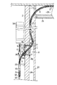
図1は参考例の壁貫通配管の壁通し具1を一戸建の建屋の外壁2の設置穴3に取付けて、配管4及び鞘管5を貫通させた状態を示す断面図である。
【0018】
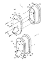
図2(a)及び(b)に示すように、この壁通し具1は第1壁通し部材6と第2壁通し部材7と連結手段とからなる。
【0019】
合成樹脂製の第1壁通し部材6は、住宅の壁としての外壁2の厚み方向両面に夫々開放されていると共に上下方向に長い小判形をなして設けられた設置穴3に、屋外側から嵌め込む第1筒部8と、この第1筒部8と一体に形成されて外側に張り出し、設置穴3の屋外側縁部と引掛かり合う第1フランジ部10と、第1筒部8の例えば屋外側端部に一体に形成されて第1筒部8の内側を閉じる閉塞部12と、この閉塞部12の下部に一体に形成されて屋内側から屋外側にかけて斜めに貫通する円筒形をなした鞘管ガイド13とから構成される。なお、前記設置穴3は、外壁2に対して直交する方向に沿って、前記外壁2を貫通している。
【0020】
鞘管ガイド13はその屋内側端部が屋外側端部よりも上側に位置するように斜めに設けられ、したがって閉塞部12の一端部から斜め下向きに突設されている。さらに、鞘管ガイド13は後述する鞘管5を挿通できるように鞘管5よりやや大径となっている。使用状態において鞘管ガイド13の屋内側端部は図3に示されるように設置穴3内に位置される。
【0021】
周方向に連続すると共に例えば閉塞部12と面一に連続した第1フランジ部10の外壁2側には、第1壁通し部材6を設置穴3に設置したときに、第1フランジ部10と外壁2との隙間を埋めて挟み込まれ雨水等の設置穴3への浸入を防止するための止水パッキン14aが設けられている。なお、前記隙間をコーキング処理する場合には止水パッキン14aは省略できる。
【0022】
閉塞部12には、この第1壁通し部材6と後述の第2壁通し部材7とを連結するための連結手段としてのねじ15をねじ込むためのねじ通孔16が第1筒部8の内側と貫通して設けられている。
【0023】
合成樹脂製の第2壁通し部材7は、外壁2に設けられた設置穴3に、屋内側から嵌め込む第2筒部17と、この第2筒部17と一体に形成されて外側に張り出し、設置穴3の屋内側縁部と引掛かり合う第2フランジ部19とからなる。周方向に連続する第2フランジ部19の外壁2側には、第2壁通し部材7を設置穴3に設置したときに、第2フランジ部19と外壁2との隙間を埋めて挟み込まれる止水パッキン14bが設けられている。この止水パッキン14bは省略してもよい。又、第2筒部17の屋外側端部の内側には、連結手段としてのねじ15を受け止めるためのねじ孔を有した螺合部21が第1壁通し部材6のねじ通孔16と対向する位置に設けられている。
【0024】
壁通し具1が設置穴3に嵌め込まれるなどして取り付けられた際に、住宅の鉛直方向に沿う第1筒部8及び第2筒部17の幅Dは、鞘管5の外径dの約2から3倍以上の寸法に形成されている。このように、第1筒部8及び第2筒部17の幅Dは、鞘管5の外径dより十分大きく形成されている。
【0025】
前記壁通し具1の具体的な寸法例を挙げると、呼び径が直径13mmの配管4を呼び径が直径28mmの鞘管5に通して、厚さ75mmの外壁2を貫通させる場合、外壁2を通る配管4及び鞘管5の外壁2に対する挿入角度が45°となるように鞘管ガイド13を閉塞部12に対して設ける。又、このとき、設置穴3の口径の最も長い方向は長さ150mm以上が望ましい。又、図3に示すように、鞘管ガイド13は鞘管5が貫通する際に接触する方向にのみ開口部があれば良く、正面から見て開口部は楕円形状でも構わない。この場合、配設に必要な壁裏空間24は幅70mm以上とする。
【0026】
次に、外壁2への壁貫通配管の壁通し具1の取付け作業を説明する。
【0027】
外壁2には予め前記第1、第2筒部8、17の大きさに合わせて設置穴3が、屋外側と屋内側とを連通して外壁2に対して直交する方向に沿って貫通して開けられている。まず、第1壁通し部材6を取付ける。第1壁通し部材6の第1筒部8を設置穴3の屋外側から屋内側へ向かって、第1フランジ部10が設置穴3の屋外側縁部に引掛かって止まるまで嵌め込む。このとき、第1フランジ部10と外壁2の屋外側との隙間は、第1フランジ部10の壁側に設けられた止水パッキン14aによって隙間無く塞がれる。
【0028】
次に、第2壁通し部材7を取付ける。第1壁通し部材6の場合とは反対に、第2壁通し部材7の第2筒部17を設置穴3の屋内側から屋外側へ向かって、第2フランジ部19が設置穴3の屋内側縁部に引掛かって止まるまで嵌め込む。このとき、前述の第1壁通し部材6の場合と同様に、第2フランジ部19と外壁2の屋内側との隙間は、第2フランジ部19の壁側に設けられた止水パッキン14bによって隙間無く塞がれる。それにより、設置穴3内で第1筒部8の屋内側端部と第2筒部17の屋外側端部とが接近する。
【0029】
この後、第1壁通し部材6の閉塞部12のねじ通孔16を通して、屋外側からねじ15を第2壁通し部材7の螺合部21にねじ込むことで、第1壁通し部材6と第2壁通し部材7とを連結すると共に、止水パッキン14a、14bが外壁2の内外両壁面に夫々圧接される。以上で外壁2の設置穴3への壁貫通配管の壁通し具1の取付けが終了する。
【0030】
この参考例の壁貫通配管の壁通し具1は第1壁通し部材6と第2壁通し部材7とをねじ15により連結しているだけなので、将来この壁貫通配管の壁通し具1を取り外す必要が生じたときには、ねじ15を緩めて外すだけで、外壁2の設置穴3からこの壁貫通配管の壁通し具1を取り外すことができる。
【0031】
次に、例えば給湯又は給水のための送液用の配管4及び鞘管5を、前述のようにして外壁2の設置穴3に取付けた壁貫通配管の壁通し具1に通す配設作業を説明する。配管4は架橋ポリエチレン管であって可撓性を有し、この配管4が通される鞘管5は配管4よりも硬質な合成樹脂製ではあるが、可撓性に優れた波付け管が採用されている。
【0032】
鞘管5は、例えば屋外から屋内へと通される。すなわち、鞘管5の一端を第1壁通し部材6の鞘管ガイド13に屋外側から斜め上向きに通していく。図3及び図4(a)、(b)に示されるように、鞘管ガイド13はこの屋内側端部が屋外側端部よりも上側に在るように閉塞部12を斜めに貫通して設けられているため、鞘管ガイド13を通して屋外から屋内へと通された鞘管5は、壁通し具1をその第2壁通し部材16に引掛かることなく斜め上向きに通り抜けて外壁2の屋内側壁面に沿って上方へと押し込まれるから、図1に示されるように、外壁2と部屋の内装板23とによって作られる幅の狭い壁裏空間24や、部屋の天井25の上の屋根裏空間26にも無理に折り曲げられて座屈変形を起こすことなく配設できる。配設し終わった鞘管5は、外壁2等に適当な間隔に取付けられるU字形をなしたサドル27等を用いてずれ落ちないように固定される。
【0033】
次に、壁通し具1を斜めに貫通して鞘管ガイド13に中間部が支持された鞘管5に対して、屋外より配管4を斜め上向きに挿入することによって、この配管4を鞘管5に沿わせて配設する。鞘管5は無理に折り曲げられることなく既に必要とされる所定の位置まで配設されているので、配管4は、無理に折り曲げられて座屈変形を起こすことなく鞘管5の内部を通って所定の位置まで案内される。鞘管5の配設及び固定作業の終了後に、図3に示すように、鞘管ガイド13の屋外側の開口部において、コーキング材28による止水処理を施して鞘管5と開口部との隙間を塞ぐ。この止水処理によって、鞘管ガイド13を通して屋外から屋内へ雨水等が浸入するおそれを極めて低くできる。なお、コーキング処理に代えて鞘管ガイド13と鞘管5との間にOリングを挟んでもよく、又、これら両止水処理を兼用してもよい。
【0034】
又、屋外側の鞘管5の他端は外壁2の屋外側に設置されたシステムアジャスタ支え29によって支持されたシステムアジャスタ30に接続される。配管4が通るシステムアジャスタ30は伸縮自在の蛇腹部31を有しており、鞘管5の屋外に露出している部分の長さに適合した高さに伸び縮みできる。又、システムアジャスタ30の下端を受けるピン付オスアダプタ33には継手32を介して配管4が接続されている。このアダプタ33は屋外に設置された給湯器34に連結されていて、給湯器34の温水等が導かれる。
【0035】
以上、説明した壁貫通配管の壁通し具1を用いた配管4及び鞘管5の配設作業によれば、外壁2に対して斜めに設けられた鞘管ガイド13に鞘管5を通すことで、外壁2の壁面に沿うように鞘管5を屋内へと配設する。第1筒部8及び第2筒部17の鉛直方向に沿った幅Dが、鞘管5の外径dより十分大きく形成されているので、鞘管5が無理に折り曲げられて座屈変形を起さない十分に広い空間Sを、第1筒部8及び第2筒部17内に確保できる。また、外壁2に対して斜めに設けられた鞘管ガイド13に鞘管5を通すことで、外壁2の壁面に沿うように鞘管5を屋内へと配設できる。
【0036】
したがって、外壁2の屋内側の狭い壁裏空間内においても鞘管5を無理に折り曲げて座屈変形を起こさせることがない。このため、鞘管5の内部に通して屋外から屋内へと配設する配管4も無理に折り曲げて座屈変形を起こさせることなく、容易に配設できる。さらに、屋外側より配管4を斜め下方に引っ張ることにより、挿入時と同様に鞘管5をガイドとして少ない抵抗で容易に配管4を引き出せるので、こうした配管4の出し入れ操作によって、将来において配管4が老朽化した場合の配管4の更新作業も簡単に行うことができる。
【0037】
又、壁貫通配管の壁通し具1の位置において鞘管5は途切れることなく屋外から屋内へと連続して配設されている。このため、屋内で配管4から水が漏れ出しても鞘管5の内部を伝わって屋外へと排出されるので、屋内への浸水のおそれが低い。しかも、鞘管5及び配管4が外壁2を貫通しており、配管4に対する継手部分は外壁2の屋外側にあるので、漏水し易い継手部分からの漏水があっても屋内への浸水のおそれがない。
【0038】
又、鞘管ガイド13はこの屋内側が屋外側よりも上側に位置するように閉塞部12を斜めに貫通して設けられているので、雨水等が斜め下向きの鞘管ガイド13を通って屋外から屋内へと浸入するおそれが殆どない。加えて、この鞘管ガイド13の屋外側の開口部にコーキング材28等による止水処理を施して鞘管5と開口部との隙間を塞いだので、より一層のこと浸水のおそれがない。
【0039】
又、第1、第2フランジ部10、19及びそれらに夫々設けられた止水パッキン14a、14bによって、外壁2の両側から設置穴3を隙間なく挟み込むサンドイッチ構造をとっているので、簡単に止水処理ができると共に、設置穴3と壁通し具1との間の埋め戻し作業等の閉栓処理も不要にでき、施工性がよい。
【0040】
又、設置穴3への壁通し具1の取付け作業と、屋内における配管4及び鞘管5の配設作業の順序はどちらが先でも構わない。又、プレハブ住宅の場合には壁通し具1を外壁2に予め取付けておくことができるから、その場合には建築現場での壁通し具1の取付けが不要であり、容易に配設作業を行うことができる。
【0041】
又、壁通し具1は正面から見た形状が上下方向に沿って長い小判形となっていて小型であるため、外壁2に設けられた設置穴3も正面から見た形状を同様の小判形とできるので、大きな円形の穴を外壁2に設ける必要がなく、設置穴3を設けることによる外壁2の強度の低下を抑制できる。
【0042】
次に、図5から図7を参照して本発明の第1の実施の形態に係る壁貫通配管の壁通し具1を説明する。なお、前述した参考例に係る壁貫通配管の壁通し具1と同一構成部分には、同一符号を付して説明を省略する。
【0043】
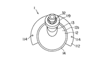
本実施の形態の壁通し具1が取付けられる設置穴3は、外壁2に対し直交する方向に沿って、この外壁2を貫通している。設置穴3は丸形に形成されている。また、本実施形態の壁通し具1は、屋外Oから屋内Iに向うにしたがって上方から下方に向って給湯器などから供給される湯を導くために用いられる。
【0044】
図5から図7に示すように、本実施形態の壁貫通配管の壁通し具1は、第1壁通し部材6だけで構成されている。本実施形態の第1壁通し部材6は、その第1筒部8が円筒状に形成されている。第1筒部8はその軸線Pが、壁通し具1が設置穴3に取付けられた際に、外壁2に対し直交する方向に沿う。
【0045】
壁通し具1が設置穴3に取付けられた際に、第1筒部8の鉛直方向に沿った幅Dは、鞘管5の外径dの約2から3倍以上の寸法に形成されている。第1筒部8の鉛直方向に沿った幅Dは、鞘管5の外径dより十分大きく形成されている。また、第1壁通し部材6は、壁通し具1が設置穴3に取付けられた際に、第1筒部8の屋外O側に露出する一端部8aに閉塞部12を設けている。
【0046】
鞘管ガイド13は、前記閉塞部12から屋外O側でかつ斜め上方に向って突出して形成されている。鞘管ガイド13は、前記軸線Pより上方に位置する閉塞部12の端部から突出している。第1筒部8の内側において鞘管ガイド13と閉塞部12との接合部には、滑らかに湾曲した湾曲面110が形成されている。鞘管ガイド13は閉塞部12の内面12aより第1筒部8の内側には突出していない。
【0047】
第1筒部8の外周面には、全周に亘って止水パッキン14が設けられている。この止水パッキン14は、第1筒部8と設置穴3の内面との間の隙間Gを埋めて、この隙間Gを通る雨水などの屋内Iへの浸入を防止する。止水パッキン14の代わりに周知のコーキング材を用いて前記隙間Gを埋めるようにしても良い。
【0048】
鞘管ガイド13の屋内I側に位置する他端部8bには、フランジ取付け部111が形成されている。このフランジ取付け部111には、設置穴3の穴縁に引掛るフランジ部材112が取付けられるようになっている。
【0049】
フランジ取付け部111は、第1筒部8の外周面に形成されかつこの外周面から凹に形成された凹溝113を複数備えている。図示例において、フランジ取付け部111は、凹溝113を二つ備えている。それぞれの凹溝113は、前記他端部8bのうち少なくとも前記軸線Pより鞘管ガイド13が設けられた側の外周面に、第1筒部8の周方向に沿って形成されている。それぞれの凹溝113は、壁通し具1が設置穴3に取付けられた際に、外壁2に沿うように形成されている。
【0050】
それぞれの凹溝113は、前記閉塞部12の表面12bからの距離が壁通し具1が取付けられる外壁2の厚みに応じた位置に形成されるのが望ましい。凹溝113は、前記閉塞部12の表面12bからの距離が互いに異なる位置に形成されている。また、それぞれの凹溝113は、前記他端部8bのうち軸線Pより鞘管ガイド13が配置されていない側の外周面には形成されていない。
【0051】
フランジ部材112は、馬蹄形に形成されているとともに、凹溝113に係合するようになっている。フランジ部材112は、壁通し具1が設置穴3内に嵌め込まれた際に、上方から凹溝113に係合する。フランジ部材112は、凹溝113に係合すると、その端面が設置穴3の穴縁に引っ掛る。
【0052】
フランジ部材112には、複数の貫通穴114が形成されている。これらの貫通穴114には、それぞれ、フランジ部材112を外壁2に固定するねじ115が通るようになっている。
【0053】
第1筒部8は、その他端部8bの縁部8cが上方から下方に向うにしたがって即ち鞘管ガイド13から離れるのにしたがって、徐々に外壁2の外面側に近づく方向に傾斜するように形成されている。この他端部8bにおいて、前記軸線Pより鞘管ガイド13が設けられた側の縁部8cは、外壁2から屋内I側に突出しているとともに、軸線Pより鞘管ガイド13が配置されていない側の縁部8cは、設置穴3の穴縁より設置穴3内に位置するように形成されている。
【0054】
前記壁通し具1の具体的な寸法例を示す。前記設置穴3は外壁2の機械的な強度を極力低下させないため、その直径を極力小さく形成するのが望ましい。呼び径が直径13mmの配管4を呼び径が直径28mmの鞘管5に通して、厚さ75mmから100mmの外壁2を貫通させる場合、外壁2を通る配管4及び鞘管5の前記軸線Pに対する挿入角度θ´が23°となるように鞘管ガイド13を閉塞部12に対して設ける。又、このとき、設置穴3の口径は、直径100mmに形成されるのが望ましい。
【0055】
次に、この第1の実施の形態の壁通し具1の外壁2の設置穴3への取付け作業を説明する。
【0056】
まず、第1壁通し部材6を、閉塞部12が屋外Oに露出するように、屋外O側から設置穴3内に嵌め込む。外壁2の厚みに応じた凹溝113にフランジ部材112を上方から係合させる。ねじ115を貫通穴114内に通して外壁2にねじ込んで、フランジ部材112とともに第1壁通し部材6を外壁2に固定する。このとき、第1筒部8と設置穴3との間の隙間Gは、止水パッキン14によって全周に亘って隙間なく埋められる。以上で外壁2の設置穴3への第1の実施の形態の壁貫通配管の壁通し具1の取付けが終了する。
【0057】
壁通し具1を外壁2に固定した後、屋内I側から鞘管5及び配管4を順次、鞘管ガイド13内に挿入する。鞘管ガイド13の先端部13aから突出した配管4の端部に、継手32を介して、2階などの上方に設置された給湯器に連結した配管116を連結する。この連結を行なう際に、図示例では以下に示す継手部117を用いる。
【0058】
継手部117は、前記継手32と、鞘管ガイド13の先端部13aの外周に形成されたねじ溝118と、このねじ溝118に螺合する継手固定部材119などを備えている。前記継手32は、金属からなりかつ鞘管ガイド13の開口縁13bと当接する鍔部120を一体に備えている。鍔部120は、継手32の全周に亘って設けられている。
【0059】
継手固定部材119は、合成樹脂などからなりかつその内周に継手32が通ることが可能な円環状に形成されている。継手固定部材119は、円筒状に形成されかつ鞘管ガイド13のねじ溝118に螺合するねじ部121と、このねじ部121の一端から内周側に向って延びた円環状の円環部122と、を一体に備えている。この円環部122は、ねじ部121がねじ溝118に螺合すると継手32の鍔部120を鞘管ガイド13の開口縁13bに向かって押圧する。
【0060】
このように、継手部117は、継手固定部材119が鞘管ガイド13のねじ溝118に螺合して、継手32の鍔部120を鞘管ガイド13の開口縁13bに向かって押圧することによって、鞘管ガイド13の開口部を雨水が入らないように閉じている。
【0061】
本実施形態によれば、設置穴3内に嵌め込まれた際に第1筒部8の鉛直方向に沿った幅Dが、鞘管5の外径dより十分大きく形成されているので、鞘管5が無理に折り曲げられて座屈変形を起さない十分に広い空間Sを第1筒部8内に確保できる。さらに、第1筒部8の屋内I側に位置する他端部8bのうち軸線Pより鞘管ガイド13が配置されていない側の縁部8cが設置穴3の穴縁より設置穴3内に位置している。
【0062】
このため、外壁2の裏側空間が狭い場合でも、鞘管5が無理に曲げることなく外壁2を貫通させてこの外壁2に沿って配設されることとなる。また、鞘管5が無理に曲げられることがないため、この鞘管5内に容易に配管4を通すことができる。
【0063】
また、この壁貫通配管の壁通し具1が取り付けられる設置穴3が、外壁2に対して直交する方向に沿って貫通しているので、雨水などが第1筒部8の外表面などを伝わって屋内に侵入することを防止できる。本実施形態において、前記設置穴3は、屋外Oから屋内Iに向かうにしたがって、徐々に上方に向かうように外壁2を貫通するように形成されても良い。この場合、雨水の浸入をより一層防止できる。なお、このとき、第1筒部8は、その軸線Pが屋外Oから屋内Iに向かうにしたがって徐々に下方に向かうように傾いて、形成されるのが望ましい。
【0064】
さらに、配管4と、給湯器などに連結した配管116とを互いに連結する継手32が、屋外Oに位置することとなる。また、鞘管5は、鞘管ガイド13の中ほどまで挿入されている。このため、たとえ、この継手32に水漏れが生じても屋内Iへの浸水を防止できる。
【0065】
また、フランジ部材112が外壁2にねじ115などによって固定されている。このため、鞘管ガイド13に新規に鞘管5及び配管4を通すときは勿論のこと、老朽化した配管4などを新品と交換するときにおいても、配管4や鞘管5を鞘管ガイド13内に通す際等に加わる操作力を、フランジ部材112に波及させて外壁2で分散して支持できる。
【0066】
このため、壁通し具1が外壁2などから不用意に外れることを防止できる。したがって、配管4の出し入れに拘わらず外壁2への鞘管5の設置状況を確実に保持することができる。
【0067】
さらに、フランジ取付け部111が、閉塞部12の表面12bからの距離が互いに異なる凹溝113を複数備えている。このため、外壁2の厚みに応じて、フランジ部材112を係合させる凹溝113を任意に選択することによって、互いに異なる厚みの外壁2に形成された設置穴3へも、容易に取付けることができる。
【0068】
なお、この例では、鞘管ガイド13の内面中ほどに突設したストッパ13dまで鞘管5を挿入するようになっているが、鞘管5は鞘管ガイド13の外まで引出されても良い。この場合、配管4も鞘管ガイド13の外に引出される。このようにすれば、配管4と配管116との接続部から水漏れが生じたときの屋内Iへの浸水をより高度に防止できる。
【0069】
次に、図8を参照して本発明の第2の実施の形態に係る壁貫通配管の壁通し具1を説明する。なお、前述した第1の実施の形態に係る壁貫通配管の壁通し具1と同一構成部分には、同一符号を付して説明を省略する。
【0070】
第2実施形態の壁通し具1の第1筒部8の一端部8aに、第2のフランジ部材130が着脱自在となっている。第2実施形態の壁通し具1の第1筒部8の一端部8aの外周には、全周に亘ってねじ溝131が形成されている。第2のフランジ部材130は、円環状に形成されており、その内周面に前記ねじ溝131に螺合するねじ溝132が全周に亘って形成されている。
【0071】
第2実施形態の壁通し具1を設置穴3に取付ける際には、予め、第2のフランジ部材130を第1筒部8に取付けておく。この第2のフランジ部材130が取付けられた第1筒部8を設置穴3内に嵌め込む。そして、前述した第9の実施の形態の壁通し具1と同様の方法で、外壁2に固定するとともに、配管4と、給湯器などと連結した配管116と、を互いに連結する。
【0072】
第2実施形態によれば、前述した第1の実施の形態の壁通し具1の効果にくわえ、外壁2をフランジ部材112と第2のフランジ部材130とによって挟み込んだ状態で取付けられている。このため、配管4や鞘管5を鞘管ガイド13内に通す際等に加わる操作力を、フランジ部材112及び第2のフランジ部材130に波及させて外壁2でより分散して支持できる。
【0073】
このため、壁通し具1が外壁2などから不用意に外れることをより確実に防止できる。したがって、配管4の出し入れに拘わらず外壁2への鞘管5の設置状況をより確実に保持できる。
【0074】
さらに、第2のフランジ部材130の第1筒部8へのねじ込み量を調整することによって、互いに異なる厚みの外壁2に形成された設置穴3へも、より容易に取付けることができる。したがって、互いに異なる厚みの外壁2への設置性がより向上する。
【0075】
又、本発明の壁貫通配管の壁通し具を用いて住宅の外壁を貫通させて屋外と屋内とにわたって配設するものは、給湯器等から延ばされる送液管に限らず、例えば、電話線などの通信系ケーブル、電線などの電力系ケーブル等であってもよい。この場合、鞘管を作る材料もこの内部に通して配設する管や線に合わせて、防電磁波能力に優れたもの等、様々な材料を使い分けることが望ましい。
【0076】
【発明の効果】
請求項1から8に記載の発明に係る壁貫通配管の壁通し具及び壁貫通構造によれば、鉛直方向に沿う筒部の幅が鞘管の外径より大きく形成されており、鞘管が無理に折り曲げられて座屈変形を起さない広い空間を筒部内に確保できることに加え、筒部の屋内側に位置する他端部のうち鞘管ガイドが配されていない側の縁部が設置穴内に位置しているので、鞘管を無理に曲げることなく外壁に沿わせて配設することができる。また、鞘管が無理に曲げられることがないため、この鞘管内に容易に配管を通すことができる。
【0077】
さらに、鞘管ガイドから屋外に露出した鞘管及び配管の先端部に周知の継手などを介して給湯器を接続することができるので、たとえ、この継手に水漏れが生じても屋内への浸水を防止できる。
【0078】
しかも、フランジ部材が設置穴の穴縁に引掛かりかつこのフランジ部材を外壁にねじ等で止めることによって、外壁に取付けることができる。このため、鞘管及び配管を鞘管ガイドに通す際等に加わる操作力を、フランジ部材に波及させて外壁で分散して支持できる。したがって、壁通し具が外壁から不用意に外れることが防止されるとともに、配管の出し入れに拘わらず外壁への鞘管の設置状況を確実に保持することができる。
【図面の簡単な説明】
【図1】 本発明の参考例に係る壁貫通配管の壁通し具を外壁に取付けて配設した状態を示す断面図。
【図2】 (a)は本発明の参考例に係る壁通し具を分解して示す斜視図。
(b)は本発明の参考例に係る壁通し具を組み立てた状態を示す斜視図。
【図3】 図1に示した状態の壁貫通配管のA部を拡大した断面図。
【図4】 (a)は鞘管が通された参考例の壁通し具を示す正面図。
(b)は鞘管が通された参考例の壁通し具を示す裏面図。
【図5】 本発明の第1の実施の形態に係る壁貫通配管用の壁通し具の使用状態を示す断面図。
【図6】 第1の実施の形態の壁通し具を示す正面図。
【図7】 第1の実施の形態の壁通し具を示す側面図。
【図8】 本発明の第2の実施の形態に係る壁貫通配管用の壁通し具の使用状態を示す断面図。
【符号の説明】
1…壁貫通配管の壁通し具、
2…外壁、
3…設置穴、
4…配管、
5…鞘管、
6…壁通し部材、
8…筒部、
8a…筒部の一端部、
8b…筒部の他端部、
8c…筒部他端部の縁部、
12…閉塞部、
13…鞘管ガイド、
13a…鞘管ガイドの先端部、
14…止水パッキン、
111…フランジ取付け部、
112…フランジ部材、
113…凹溝、
115…ねじ、
117…継手部、
32…継手、
119…継手固定部材、
120…鍔部。[0001]
BACKGROUND OF THE INVENTION
The present invention, for example, separates a pipe for feeding liquid extending from an outdoor device such as a water heater installed outdoors such as a detached house, from the outdoors.The outer wallThe present invention relates to a wall through structure of a wall through pipe and a wall through tool of the wall through pipe to be disposed through.
[0002]
[Prior art]
As a technique for drawing a pipe connected to a water heater installed outdoors in a house into the room, a technique described in FIG. 3 of JP-A-9-105482 is known.
[0003]
In this prior art, a through-hole (installation hole) is provided in a wall, a fixture is attached to the through-hole from the outdoor side, and one end of a hot water supply pipe comprising a sheath pipe and a pipe passed through the sheath pipe is provided. It is attached to the indoor distributor (header), and only the piping is passed through the fixture and attached to the outdoor water heater.
[0004]
At this time, a fixing tool is attached to the wall, a hot water supply pipe composed of a pipe and a sheath pipe is provided from the distributor (header) to the fixing tool, and the sheath pipe is cut at the position of the fixing tool. The part is brought into contact with the fixture, and the pipe is passed through a water-stopping member that projects obliquely upward to the outdoor side of the fixture, so that only this pipe passes through the wall, and the intermediate part of this pipe is fixed to the fixture. The piping drawn to the outdoor side is attached to the water heater.
[0005]
[Problems to be solved by the invention]
Since the above-mentioned conventional technology penetrates the pipe diagonally with respect to the wall, it is excellent in that the load on the pipe is small when the pipe runs along the inner and outer surfaces of the wall and that the pipe can be inserted and removed from the outdoor side for renewal. ing.
[0006]
However, since the oblique water-stopping member projecting to the outdoor side with respect to the wall is not connected to another sheath pipe, the sheath pipe or the pipe is passed through the water-stopping member and the sheath pipe. There is a problem that the tip of the pipe hits the end of the water stop member and it is difficult to pass the pipe, and the sheath pipe is easily pushed by the pipe when passing the pipe from the outdoor side, so that the workability through the pipe is not good.
[0007]
The problem to be solved by the present invention is to forcibly bend the sheath tube to the outer wall.Keep it alongThe object is to obtain a wall through structure of a wall through pipe and a wall through tool of the wall through pipe that can be disposed and can easily pass through the pipe.
[0008]
[Means for Solving the Problems]
The wall threading tool of the wall through pipe of the present invention has a cylindrical portion fitted in an installation hole penetrating along a direction orthogonal to the outer wall, and an inner side of the cylindrical portion at one end portion of the cylindrical portion exposed to the outside. A closed portion provided integrally with the closed portion, and a sheath tube that is formed integrally with the closed portion and that protrudes obliquely upward from the upper portion of the closed portion and that penetrates the outer wall. A cylindrical sheath tube guide to be inserted and attached to the outer periphery of a flange mounting portion formed at the other end of the cylindrical portion protruding from the installation hole to the indoor side, on the indoor side surface of the outer wall A flange member fixed in contact therewith, and an edge on the lower side of the other end of the tube portion fitted in the installation hole is positioned in the installation hole, and the sheath tube is formed in the tube portion. In the vertical direction of the tube so that it can be bent without buckling deformation It is characterized in that the cormorants width is formed larger than the outer diameter of the sheath tubeThe
[0009]
In the wall threading tool of the wall through pipe according to the present invention, it is preferable that the edge portion of the other end portion of the cylindrical portion is inclined so as to gradually approach the outer surface side of the outer wall as it goes downward from above.
[0010]
In the wall threading tool of the wall through pipe of the present invention, a screw groove is provided on the outer periphery of the one end portion of the cylindrical portion, and is screwed into the screw groove and attached to the one end portion, and the outer wall is connected to the flange member. It is preferable to provide another flange member that is fixed to the outer wall with the gap between the two.
[0011]
In the wall threading tool of the wall through pipe according to the present invention, the flange mounting portion includes a plurality of concave grooves having different distances from the closing portion on an outer periphery thereof, and the concave grooves selected according to the thickness of the outer wall. Preferably, the flange member is engaged with.
[0012]
In the wall threading tool of the wall through pipe of the present invention, it is preferable that the concave groove is formed along the circumferential direction of the cylindrical portion and the flange member is formed in a horseshoe shape.
[0013]
In the wall threading tool of the wall through pipe of the present invention, it is preferable to include a water-stopping packing or a caulking material that fills a space between the outer peripheral surface of the cylindrical portion and the inner surface of the installation hole.
[0014]
In the wall threading tool of the wall through pipe according to the present invention, the sheath pipe guide includes a joint portion connecting an outdoor pipe and the pipe projecting from the sheath pipe guide at a distal end portion of the sheath pipe guide. A joint having a flange portion that abuts on the distal end surface of the tube guide and the pipes are connected to each other, and screwed into the distal end portion of the sheath tube guide to press the flange portion against the distal end surface of the sheath tube guide. It is preferable to provide a joint fixing member.
[0015]
The wall penetration structure of the wall penetration pipe of the present invention uses the above-mentioned wall threading tool, and arranges the cylindrical portion in an installation hole penetrating along the direction orthogonal to the outer wall. A pipe that is inserted into a sheath pipe guide that protrudes to the outdoor side is bent so as not to buckle and deform in the cylindrical portion starting from the sheath pipe guide, and a pipe that penetrates the outer wall in the sheath pipe It is characterized by being passed.
[0016]
DETAILED DESCRIPTION OF THE INVENTION
Hereinafter, the present invention will be described with reference to FIGS.Reference exampleThe wall threading tool of the wall through pipe according to the above will be described.
[0017]
Figure 1Reference exampleIt is sectional drawing which shows the state which attached the wall through
[0018]
As shown in FIGS. 2A and 2B, the
[0019]
The first wall-passing
[0020]
The
[0021]
When the first
[0022]
The closing
[0023]
The second wall-passing
[0024]
When the
[0025]
As a specific example of the dimensions of the
[0026]
Next, an operation of attaching the
[0027]
The
[0028]
Next, the second
[0029]
Thereafter, the
[0030]
thisReference exampleSince the
[0031]
Next, for example, an arrangement operation is performed in which the
[0032]
The
[0033]
Next, it penetrates through the
[0034]
The other end of the
[0035]
As described above, according to the arrangement work of the
[0036]
Therefore, even in the narrow wall space on the indoor side of the
[0037]
Further, the
[0038]
Further, since the
[0039]
In addition, since the first and
[0040]
Further, the order of the work of attaching the
[0041]
Further, since the shape of the
[0042]
next,5 to 7Refer to the present inventionFirst embodimentThe
[0043]
The
[0044]
5 to 7As shown in FIG. 1, the
[0045]
When the
[0046]
The
[0047]
A water-stop packing 14 is provided on the outer peripheral surface of the
[0048]
A flange mounting portion 111 is formed on the
[0049]
The flange mounting portion 111 includes a plurality of
[0050]
Each of the
[0051]
The
[0052]
A plurality of through
[0053]
The
[0054]
The example of a specific dimension of the said
[0055]
Then thisFirst embodimentAn operation of attaching the
[0056]
First, the first
[0057]
After fixing the
[0058]
The
[0059]
The
[0060]
As described above, the
[0061]
According to the present embodiment, the width D along the vertical direction of the
[0062]
For this reason, even when the back side space of the
[0063]
Moreover, since the
[0064]
Further, the joint 32 that connects the
[0065]
Further, the
[0066]
For this reason, it can prevent that the
[0067]
Further, the flange mounting portion 111 includes a plurality of
[0068]
In this example, the
[0069]
next,FIG.Refer to the present inventionSecond embodimentThe
[0070]
Second embodimentA
[0071]
Second embodimentWhen attaching the
[0072]
Second embodimentAccording to the previously mentionedFirst embodimentIn addition to the effect of the
[0073]
For this reason, it can prevent more reliably that the
[0074]
Furthermore, by adjusting the screwing amount of the
[0075]
Moreover, the thing which penetrates the outer wall of a house using the wall threading tool of the wall penetration piping of this invention and is arrange | positioned over the outdoors and indoors is not restricted to the liquid feeding pipe extended from a water heater etc., for example, a telephone line It may be a communication system cable such as a power system cable such as an electric wire. In this case, it is desirable to use various materials such as those having excellent anti-electromagnetic wave capability in accordance with the pipes and wires arranged through the interior of the sheath pipe.
[0076]
【The invention's effect】
According to the wall threading tool and the wall penetrating structure of the wall through pipe according to the invention described in
[0077]
Furthermore, since a water heater can be connected to the tip of the sheath pipe and piping exposed from the sheath pipe guide to the outside through a well-known joint, etc., even if water leaks in this joint, Can be prevented.
[0078]
Moreover, the flange member can be attached to the outer wall by catching on the hole edge of the installation hole and fastening the flange member to the outer wall with a screw or the like. For this reason, the operating force applied when the sheath tube and the pipe are passed through the sheath tube guide can be dispersed and supported by the outer wall by spreading to the flange member. Accordingly, it is possible to prevent the wall threading tool from being inadvertently detached from the outer wall, and to reliably maintain the installation state of the sheath tube on the outer wall regardless of the insertion and removal of the pipe.
[Brief description of the drawings]
FIG. 1 of the present inventionReference exampleSectional drawing which shows the state which attached and arrange | positioned the wall threading tool of the wall penetration piping which concerns on an outer wall.
FIG. 2 (a) shows the present invention.Reference exampleThe perspective view which decomposes | disassembles and shows the wall threading tool which concerns on.
(B) of the present invention.Reference exampleThe perspective view which shows the state which assembled the wall threading tool which concerns on.
3 is an enlarged cross-sectional view of a portion A of the wall through pipe in the state shown in FIG.
[Fig. 4] (a) is a sheath tube passedReference exampleThe front view which shows the wall threading tool.
(B) A sheath tube was passedReference exampleThe back view which shows a wall threading tool.
[Figure 5]Sectional drawing which shows the use condition of the wall threading tool for wall penetration piping which concerns on the 1st Embodiment of this invention.
[Fig. 6]The front view which shows the wall threading tool of 1st Embodiment.
[Fig. 7]The side view which shows the wall threading tool of 1st Embodiment.
[Fig. 8]Sectional drawing which shows the use condition of the wall threading tool for wall penetration piping which concerns on the 2nd Embodiment of this invention.
[Explanation of symbols]
1 ... Wall threading tool for through-wall piping,
2 ... Outer wall,
3 ... Installation hole,
4 ... Piping,
5 ... sheath tube,
6 ... Wall-passing member,
8 ... Cylinder part,
8a: one end of the cylinder,
8b ... the other end of the cylinder,
8c ... the edge of the other end of the tube,
12 ... Occlusion part,
13 ... Sheath tube guide,
13a ... the tip of the sheath guide,
14 ... Water stop packing,
111 ... Flange mounting part,
112 ... Flange member,
113 ... concave groove,
115 ... screw,
117 ... joint part,
32 ... Fitting,
119 ... Joint fixing member,
120 ... Buttocks.
Claims (8)
屋外に露出する前記筒部の一端部にこの筒部の内側を閉じて一体に設けられた閉塞部と、
この閉塞部と一体に形成されるとともに前記筒部の外側に位置して前記閉塞部の上部から斜め上方に突出して、前記外壁を貫通する鞘管が挿入される筒状の鞘管ガイドと、
前記設置穴から屋内側に突出される前記筒部の他端部に形成されたフランジ取付け部の外周に取付けられて、前記外壁の屋内側の面に接して固定されるフランジ部材と、
を具備し、
前記設置穴に嵌め込まれた前記筒部の他端部の下部側の縁部が前記設置穴内に位置されるとともに、前記筒部内で前記鞘管が座屈変形を起こさないで曲げられるように前記筒部の鉛直方向に沿う幅が前記鞘管の外径より大きく形成されていることを特徴とする壁貫通配管の壁通し具。 A cylinder part fitted in an installation hole penetrating along a direction orthogonal to the outer wall;
A closing part integrally provided by closing the inside of the cylindrical part at one end of the cylindrical part exposed outdoors;
A cylindrical sheath guide that is formed integrally with the closed portion and is located outside the cylindrical portion and protrudes obliquely upward from the upper portion of the closed portion, into which a sheath tube penetrating the outer wall is inserted,
A flange member that is attached to the outer periphery of the flange mounting portion formed at the other end portion of the cylindrical portion that protrudes indoors from the installation hole, and is fixed in contact with the indoor side surface of the outer wall;
Comprising
The lower edge of the other end of the cylindrical portion fitted in the installation hole is positioned in the installation hole, and the sheath tube is bent without causing buckling deformation in the cylindrical portion. A wall threading tool for a through-wall pipe, wherein a width along a vertical direction of the cylindrical portion is formed larger than an outer diameter of the sheath pipe .
Priority Applications (1)
| Application Number | Priority Date | Filing Date | Title |
|---|---|---|---|
| JP02241399A JP4278754B2 (en) | 1998-09-22 | 1999-01-29 | Wall through structure of wall through pipe and wall through tool of wall through pipe |
Applications Claiming Priority (7)
| Application Number | Priority Date | Filing Date | Title |
|---|---|---|---|
| JP26844898 | 1998-09-22 | ||
| JP29380798 | 1998-10-15 | ||
| JP10-305670 | 1998-10-27 | ||
| JP10-268448 | 1998-10-27 | ||
| JP10-293807 | 1998-10-27 | ||
| JP30567098 | 1998-10-27 | ||
| JP02241399A JP4278754B2 (en) | 1998-09-22 | 1999-01-29 | Wall through structure of wall through pipe and wall through tool of wall through pipe |
Related Child Applications (2)
| Application Number | Title | Priority Date | Filing Date |
|---|---|---|---|
| JP2005276713A Division JP4279278B2 (en) | 1998-09-22 | 2005-09-22 | Wall through structure of wall through pipe and wall through tool of wall through pipe |
| JP2005276714A Division JP4369913B2 (en) | 1998-09-22 | 2005-09-22 | Wall through structure of wall through pipe and wall through tool of wall through pipe |
Publications (3)
| Publication Number | Publication Date |
|---|---|
| JP2000199584A JP2000199584A (en) | 2000-07-18 |
| JP2000199584A5 JP2000199584A5 (en) | 2005-11-10 |
| JP4278754B2 true JP4278754B2 (en) | 2009-06-17 |
Family
ID=27457763
Family Applications (1)
| Application Number | Title | Priority Date | Filing Date |
|---|---|---|---|
| JP02241399A Expired - Lifetime JP4278754B2 (en) | 1998-09-22 | 1999-01-29 | Wall through structure of wall through pipe and wall through tool of wall through pipe |
Country Status (1)
| Country | Link |
|---|---|
| JP (1) | JP4278754B2 (en) |
Families Citing this family (10)
| Publication number | Priority date | Publication date | Assignee | Title |
|---|---|---|---|---|
| JP2002181245A (en) * | 2000-12-15 | 2002-06-26 | Sekisui Chem Co Ltd | Drawing out tool of liquid feeding pipe and its piping structure |
| JP4541587B2 (en) * | 2001-05-09 | 2010-09-08 | 未来工業株式会社 | Piping material drawing tool and piping material drawing structure |
| JP2008116054A (en) * | 2007-12-14 | 2008-05-22 | Mirai Ind Co Ltd | Piping cover device |
| JP5224406B2 (en) * | 2010-07-22 | 2013-07-03 | 古河電気工業株式会社 | Pipe wall through structure, pipe wall through member, and through pipe fixing method to wall |
| FR2971035B1 (en) * | 2011-01-27 | 2014-01-10 | Cg Distrib | DEVICE FOR EXITING ENHANCED FLUID CIRCULATION TUBES |
| JP5850635B2 (en) * | 2011-04-25 | 2016-02-03 | 旭化成ホームズ株式会社 | Hot water pipe arrangement structure |
| JP2013031270A (en) * | 2011-07-27 | 2013-02-07 | Toyota Home Kk | Wiring structure of charging power source and dwelling |
| JP5841003B2 (en) * | 2012-05-07 | 2016-01-06 | ミサワホーム株式会社 | Piping cover and piping cover mounting structure |
| JP2018028346A (en) * | 2016-08-17 | 2018-02-22 | 株式会社カクダイ | Pipe support tool |
| JP6916517B2 (en) * | 2017-07-14 | 2021-08-11 | 株式会社イトーヨーギョー | Protective tube fixtures for wire containment equipment |
-
1999
- 1999-01-29 JP JP02241399A patent/JP4278754B2/en not_active Expired - Lifetime
Also Published As
| Publication number | Publication date |
|---|---|
| JP2000199584A (en) | 2000-07-18 |
Similar Documents
| Publication | Publication Date | Title |
|---|---|---|
| US20210310224A1 (en) | Flexible drainage trap | |
| US5971444A (en) | Through wall connector | |
| JP4278754B2 (en) | Wall through structure of wall through pipe and wall through tool of wall through pipe | |
| US5347767A (en) | Fire retardant sleeve | |
| RU2210018C2 (en) | Preassembled pipe fitting for use with corrugated pipeline (versions) | |
| US7810847B1 (en) | Sleeve coupling | |
| US5195784A (en) | Method and means for absorbing movement in pipelines | |
| JP4369913B2 (en) | Wall through structure of wall through pipe and wall through tool of wall through pipe | |
| CA2118898A1 (en) | Passthrough Device with Firestop | |
| WO2010112851A2 (en) | Pipe coupler | |
| JP2000199584A5 (en) | ||
| JP4279278B2 (en) | Wall through structure of wall through pipe and wall through tool of wall through pipe | |
| EP3232109B1 (en) | Use of a piping system with protection against fire | |
| KR200299546Y1 (en) | Pipe connect box structure of broadcasting speaker of building | |
| KR200387795Y1 (en) | A Connection Tap | |
| EP1881576A1 (en) | Cable gland assemblies | |
| US4973014A (en) | Conduit bracket lock system | |
| JPH08209786A (en) | Connection structure of toilet bowl and discharge water pipe | |
| JP2009236317A (en) | Connecting joint and piping method using the same | |
| DE19509399A1 (en) | Noise reduction housing for heating and sanitation ducts | |
| JP4541587B2 (en) | Piping material drawing tool and piping material drawing structure | |
| CN210441298U (en) | Ground heating installation structure without damaging waterproof layer of toilet | |
| KR100929796B1 (en) | Pipe line waterproofing device for transmission and distribution | |
| CN215981285U (en) | Air duct | |
| KR102228980B1 (en) | Supporting apparatus of freezing protection heating cable inside the vertical pipe |
Legal Events
| Date | Code | Title | Description |
|---|---|---|---|
| A521 | Written amendment |
Free format text: JAPANESE INTERMEDIATE CODE: A523 Effective date: 20050922 |
|
| A621 | Written request for application examination |
Free format text: JAPANESE INTERMEDIATE CODE: A621 Effective date: 20050922 |
|
| A977 | Report on retrieval |
Free format text: JAPANESE INTERMEDIATE CODE: A971007 Effective date: 20080707 |
|
| A131 | Notification of reasons for refusal |
Free format text: JAPANESE INTERMEDIATE CODE: A131 Effective date: 20080715 |
|
| A521 | Written amendment |
Free format text: JAPANESE INTERMEDIATE CODE: A523 Effective date: 20080916 |
|
| TRDD | Decision of grant or rejection written | ||
| A01 | Written decision to grant a patent or to grant a registration (utility model) |
Free format text: JAPANESE INTERMEDIATE CODE: A01 Effective date: 20090224 |
|
| A01 | Written decision to grant a patent or to grant a registration (utility model) |
Free format text: JAPANESE INTERMEDIATE CODE: A01 |
|
| A61 | First payment of annual fees (during grant procedure) |
Free format text: JAPANESE INTERMEDIATE CODE: A61 Effective date: 20090311 |
|
| FPAY | Renewal fee payment (event date is renewal date of database) |
Free format text: PAYMENT UNTIL: 20120319 Year of fee payment: 3 |
|
| FPAY | Renewal fee payment (event date is renewal date of database) |
Free format text: PAYMENT UNTIL: 20120319 Year of fee payment: 3 |
|
| FPAY | Renewal fee payment (event date is renewal date of database) |
Free format text: PAYMENT UNTIL: 20120319 Year of fee payment: 3 |
|
| FPAY | Renewal fee payment (event date is renewal date of database) |
Free format text: PAYMENT UNTIL: 20130319 Year of fee payment: 4 |
|
| FPAY | Renewal fee payment (event date is renewal date of database) |
Free format text: PAYMENT UNTIL: 20130319 Year of fee payment: 4 |
|
| FPAY | Renewal fee payment (event date is renewal date of database) |
Free format text: PAYMENT UNTIL: 20140319 Year of fee payment: 5 |
|
| EXPY | Cancellation because of completion of term |