JP4277459B2 - Ink jet printer and ink particle ejection method - Google Patents
Ink jet printer and ink particle ejection method Download PDFInfo
- Publication number
- JP4277459B2 JP4277459B2 JP2001091494A JP2001091494A JP4277459B2 JP 4277459 B2 JP4277459 B2 JP 4277459B2 JP 2001091494 A JP2001091494 A JP 2001091494A JP 2001091494 A JP2001091494 A JP 2001091494A JP 4277459 B2 JP4277459 B2 JP 4277459B2
- Authority
- JP
- Japan
- Prior art keywords
- nozzle
- image data
- nozzles
- ink particles
- Prior art date
- Legal status (The legal status is an assumption and is not a legal conclusion. Google has not performed a legal analysis and makes no representation as to the accuracy of the status listed.)
- Expired - Fee Related
Links
Images


Landscapes
- Ink Jet (AREA)
Description
【0001】
【発明の属する技術分野】
本発明は、インクジェットプリンタにおいてヘッドの駆動のために用いられる電圧波形を生成する際の技術に関し、特にディジタルデータからアナログの波形を生成する回路周辺の技術に関する。
【0002】
【従来の技術】
一般にホストコンピュータと接続して用いられるプリンタでは、ホストコンピュータから印刷命令を受信し、その命令を解釈して、そこに含まれるイメージデータをイメージバッファメモリに対して一旦展開しておく。インクジェット方式のプリンタにおいて、このイメージバッファメモリに展開されるデータは、ヘッドを1回主走査させる間に描き出されるドット数、すなわち1バンド分のデータを基本単位とするのが通常である。
【0003】
最近のインクジェットヘッドにおいては、印刷品質及び印刷速度を向上させるために、例えば1色につき96ものノズルが副走査方向に列をなして並べられる。そしてプリンタの画像処理部が、このノズルの各々に1対1の対応関係をもって、イメージバッファの各ビットにデータを展開していく。ビットの立ったところではインク粒の吐出をオンとし、ビットの立っていないところでは吐出をオフとする。
【0004】
インク粒を吐出する場面にあっては、より高画質の印刷物を得るために吐出するインク粒の大きさを打ち分けられるようにしている。以下に、それを実現するための代表的技術の概要について説明する。
【0005】
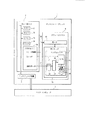
図1は、インクジェットプリンタのハードウエア構成を表す。図1においてコントローラ2は、プリンタ内に実装される制御基板であって、インタフェース装置4から入力されるデータに従った印刷動作を、プリントエンジン3に実行させる。CPU(Central Processing Unit:中央演算処理装置)23は、ROM(Read Only Memory:読出し専用記憶素子)21に格納されたプログラムを実行することにより、コントローラ2内の各部を制御する。コントローラ2のメインバスには、CPU23の主記憶装置として働くRAM(Random Access Memory:読み書き可能記憶素子)22や各種設定項目を記録しておくためのPROM(Programable Read Only Memory:再書き込み可能読出し専用記憶素子)24が接続されている。
【0006】
コントローラ2内のカスタムICチップ26は、CPU23によって解釈された印刷命令に従い、実際にプリントエンジン3に対して各種信号を送出し、これを動作させる。すなわちカスタムICチップ26は、プリンタの印字駆動に関する部分の統轄制御を行なうエンジン制御部としての役割を果たす。
【0007】
カスタムICチップ26から信号線28を介して送出されるモータ駆動信号は、モータ29に印刷用紙の紙送りをおこなわせたり、キャリッジ30に搭載されるヘッドユニット31を移動させたりする。
【0008】
信号線32は、印字ヘッドに搭載されるノズル数に対応するビット幅を有するバスラインであって、RAM22に展開されるイメージバッファデータに基づいて、各ノズル毎のインクの吐出又は吐出停止の信号を、印字ヘッドに対して送出する。この際、印字ヘッドの駆動電圧は、D/AコンバータICチップ33によって生成されるアナログの電圧波形に従う。
【0009】
インク粒の大きさを決定するためのアナログ信号は、ディジタルのベクトルデータの集まりの形式で、一旦、ディジタル/アナログコンバータ33に送られる。ここでディジタル信号は、図2において一例を示すようなアナログの台形波に変換されてから、インクノズル駆動用スイッチング半導体素子35に送られる。このアナログの電圧を生成するために用いられるのが、図3に表すような外観を呈するトランジスタ34である。
【0010】
図4は、代表的なインクジェットプリンタの例として、圧電振動子の伸長作用を利用することによりノズルからインクを吐出させる方式の場合における、ヘッド駆動回路の構成を表している。
【0011】
図4において、各スイッチング回路35(35の1〜35のn)はディジタルとアナログの2つの入力を持ち、これら入力に従ったアナログの駆動信号を圧電振動子37(37の1〜37のn)に対して出力する。各スイッチング回路35の入力信号線のうち、一方は、そのノズルにおけるインクの吐出及び吐出停止の状態を表すディジタル入力信号線32である。このディジタル信号線32は、カスタムICチップ26(図1)からの入力に接続されている。カスタムICチップ26から直列で入力されたデータは、各シフトレジスタ41(41の1〜41のn)に連続して転送され、所定のタイミングでラッチされてスイッチング回路35に入力される。
【0012】
各スイッチング回路35の入力信号線のうちの、もう一方の入力信号線は、前述のトランジスタ34から入力され、吐出すべきインク粒の大きさ等を決定させるためのアナログ波形入力信号線36である。
【0013】
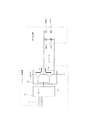
図5は、上記のD/AコンバータICチップ33によりアナログ変換された電圧波形が、アナログスイッチ(35の1〜35のn)を介して圧電振動子(37の1〜37のn)に印加される際の実際の様子について説明するための回路図である。図5においては、アナログ信号線についてのみ表記している。
【0014】
例えば、電圧波形を構成する線分が上向きの勾配を持つものであるとき(図2におけるT1からT2の区間、及びT5からT6の区間)、電源からNPNトランジスタを介して、矢印A1方向に電流が流され充電される。逆に、電圧波形を構成する線分が下向きの勾配を持つものであるときには(図2におけるT3からT4の区間、及びT7からT8の区間)、PNPトランジスタを介してグラウンドに向かって矢印A2の方向に電流が放電される。
【0015】
これら充電及び放電時に各トランジスタに流れる電流は、短時間に大きな電圧変位があったときに、より大きな値となる。図2に表す例を用いて説明すれば、時刻T3からT4にかけての時間tの間に、変位量デルタVの電圧変化があったときが、PNPトランジスタに最も電流が流れるときであって、その値は電圧変位量デルタVに比例し、時間tに反比例する。このように、短時間に大きな電圧変位を圧電振動子37に対して与えれば、振動子37は大きな形状変化を起こすことから、インク溜まり38を強く押し下げることとなって、概して大きなインク粒を吐出させることとなる。
【0016】
上記のように2つのトランジスタによって圧電振動子35が駆動される際には、トランジスタの発熱が避けられない。従って、図3に表したようにトランジスタ34にはかなり大型のヒートシンクが取り付けられている。
【0017】
インクジェットプリンタの実際の標準的組立工程では、例えばブラック、イエロー、シアン、マゼンダ、ライトシアン、ライトマゼンダ及びダークイエローの合計7つのノズル群で1ヘッドを構成する。そして、各ノズル群に対して、各々インクノズル駆動用スイッチング半導体素子が取り付けられる。例えば、各色につき96個(n=96)のノズルで構成されるインクヘッドを搭載するプリンタの場合、1チップで構成されるこのインクノズル駆動用スイッチング半導体素子には、前述のようなスイッチング回路が96個組み含まれる。そして、インクジェットプリンタの組立てに際しては、各チップが、各ノズル群に対して取り付けられる。
【0018】
その各々を1つのトランジスタで駆動しようとするときは、合計672の圧電振動子に対して電圧を印加することになる。ここでは、1色についてのノズル数(96ノズル)について全てを吐出した場合を、ノズル稼働率100%として説明する。すなわち、7色インクについて全672ノズルからインクの吐出を行なわせる場合は、ノズル稼働率700%となる。
【0019】
【発明が解決しようとする課題】
上述のようなカラーインクジェットプリンタを用いて通常の印刷動作を実行する場合において、全ての色のヘッドにおける全ノズルから同時にインクを吐出させるようなこと、すなわちノズル稼働率700%となることは考えられない。例えば、印刷見本としてよく用いられることがあるようなトゥルーカラーのビットマップデータを印刷するような場合であっても、通常、ノズル稼働率が130%を超えるようなことは殆どない。
【0020】
しかし、従来における実装部品選定の段階では、これら全てのノズルが同時に駆動した場合に備えて、ノズル稼働率700%にも耐え得るようなトランジスタを採用することとしていた。例えばノズルクリーニングを行なうときには、目詰まり解消のため、全てのノズルからインク粒を吐出させる。従って、従来はこのような例外的動作にも対処させなければならなかったのである。
【0021】
また、ホストコンピュータから送られてくる印刷命令に含まれるイメージデータにおけるノズル稼働率は、一般に予測不可能であった。すなわち、もし全てのカラーインクを用いての黒ベタの印刷を行なうようなことがあれば、容易にノズル稼働率は200%を超えるような値になってしまうかもしれない。
【0022】
従来のインクジェトプリンタでは、上記のような例外的動作に対処するための特別な機能は備えていなかった。そのため、今後益々ノズル数が増加するに従って、台形波の増幅用に非常に大電流を流し得るトランジスタを用意しなければならなくなる。また、それに伴ってトランジスタ冷却用に、非常に巨大なヒートシンクをも実装させなければならなくなる事態ともなり得る。さらには、この台形波増幅用のトランジスタ及び周辺回路を、複数組用意して対処しなければならなくなることも考えられる。
【0023】
本発明は、上記のような事情に鑑みなされたものである。本発明では、特別に余裕を持たせたトランジスタ部品を選定したり、あるいは特別に巨大なヒートシンクを実装させたりすることなく、上記のような異常事態にも対処可能な技術を提供するものである。
【0024】
【課題を解決するための手段】
上記課題を解決するため、本発明の印刷命令生成部では、予め設定されたノズル稼働率を超えるようなプリントヘッドの駆動を行なわせない。すなわち本発明は、イメージデータを含む印刷命令を送信する印刷命令生成部と、前記印刷命令を受信して、当該印刷命令に従った処理を実行するインクジェットプリンタのプリントコントローラとからなる画像処理装置に適用される。
【0025】
上記構成の画像処理装置において、前記印刷命令生成部は、前記印刷命令中に、前記インクジェットプリンタのヘッドにおける全ノズル中、所定の数以上のノズルを同時に稼働させることとなるイメージデータを含ませないよう構成されている。
【0026】
また、上記の画像処理装置において、前記所定の数は、前記インクジェットプリンタのヘッド駆動回路において、ヘッド駆動用電圧波形を増幅するためのトランジスタが消費する電流の値が、当該トランジスタの最大許容電流値に相当する値となるときの駆動ノズル数である。このように構成すれば、台形波増幅用のトランジスタに、その能力を超える過大な電流が流されることがない。
【0027】
一方、本発明のインクジェットプリンタは、以下のような構成を採る。すなわち本発明は、印刷命令生成部から印刷命令を受信して、当該命令に含まれるイメージデータを、列をなすノズルに対してマッピングする形式でイメージバッファメモリに展開する画像処理部と、当該イメージバッファメモリにマッピングされたデータに従って、前記ノズルを駆動するための素子に対して電圧を印加することによりインク粒の吐出を行わせる駆動制御部とを有するインクジェットプリンタに適用される。
【0028】
上記構成のインクジェットプリンタにおいて、前記駆動制御部が吐出させるインク粒の大きさを決定させるための電圧波形信号を増幅するトランジスタの消費電流値が、当該トランジスタの最大許容電流値以上となるような数のノズルに対して、前記画像処理部が、マッピングを行なう場合に、前記駆動制御部は、前記イメージバッファメモリにマッピングされたデータに基づくインク粒の吐出を、二以上の走査回数に分散して実行させるよう構成されている。
【0029】
これにより、前記トランジスタの消費電流値が、当該トランジスタの最大許容電流値以下となるようにすることができる。
【0030】
上記課題を解決するためのプログラムは、特定の記録媒体に格納して保持させることが可能である。本発明のプログラムを格納した記録媒体は、以下のような制御内容を実現するプログラムを格納するものである。すなわち、このプログラムは、中央演算処理装置(CPU)に、プリンタを制御させるための印刷命令を生成させるためのプログラムであって、前記印刷命令中に、制御対象たるプリンタのヘッドにおける全ノズル中、所定の数以上のノズルを同時に稼働させることとなるイメージデータを含ませないことを特徴とする。
また、上記課題を解決するための印刷命令生成部における画像処理方法は、イメージデータを含む印刷命令を送信する印刷命令生成部と、前記印刷命令を受信して、当該印刷命令に従った処理を実行するインクジェットプリンタのプリントコントローラとからなる画像処理装置の画像処理方法であって、前記印刷命令生成部は、前記印刷命令中に、前記インクジェットプリンタのヘッドにおける全ノズル中、所定の数以上のノズルを同時に稼働させることとなるイメージデータを検出し、前記イメージデータを分割し、分割されたイメージデータ各々をプリントコントローラに別個に送信することを特徴とする。
更に、上記課題を解決するための駆動制御部における画像処理方法は、印刷命令生成部から印刷命令を受信して、当該命令に含まれるイメージデータを、列をなすノズルに対してマッピングする形式でイメージバッファメモリに展開する画像処理部と、当該イメージバッファメモリにマッピングされたデータに従って、前記ノズルを駆動するための素子に対して電圧を印加することによりインク粒の吐出を行わせる駆動制御部とを有するインクジェットプリンタの画像処理方法において、
前記駆動制御部が吐出させるインク粒の大きさを決定させるための電圧波形信号を増幅するトランジスタの消費電流値が、当該トランジスタの最大許容電流値以上となるような数のノズルに対して、前記画像処理部がマッピングを行うことを検出し場合に、
前記駆動制御部は、前記イメージバッファメモリにマッピングされたデータに基づくインク粒の吐出を、二以上の走査回数に分散して実行させることを特徴とする。
【0031】
【発明の実施形態】
以下、本発明の1実施形態について図面を参照して説明する。本発明は、従来技術の説明において既に述べたようなインクジェットプリンタについて適用される。実施形態において特徴的な点は、ホストコンピュータ5が有する機能、及びインクジェットプリンタ1におけるプリントコントローラ2が有する機能にある。
【0032】
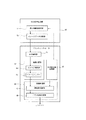
図6は、本発明の印刷システムにおける上記機能の内容を表すブロック図である。図6において、印刷命令生成部50は、ホストコンピュータ5側においてプリンタドライバ等のソフトウエアにより提供される機能ブロックである。これらソフトウエアは、ハードディスクドライブ等の記録媒体に格納されて、ホストコンピュータ5によって実行可能に保持される。
【0033】
印刷命令生成部50は、アプリケーションプログラムが発行する印刷要求に基づいて、イメージデータを生成し、必要なコマンドを付加してプリンタに対して送出する。実施形態の印刷命令生成部50におおいて特徴的な点は、最大稼働率設定部51が、プリンタ側のハードウエア(トランジスタ34)の能力に従って、プリントヘッドに搭載される全ノズルのうち、所定の数以上のノズルを同時に稼働させることがないようにノズルの稼働率を設定するところにある。さらに、イメージデータ分割部52は、前記稼働率を上回るようなイメージデータについては、これを分割してプリンタ側に送出するようにしている。
【0034】
例えば、従来技術の説明において例示したような、各色につき96ノズルを有し、7色のインクで構成されるようなプリントヘッドを搭載するプリンタ1がホストコンピュータ5と双方向通信可能に接続されているとする。プリンタ1側には、台形波増幅のためのトランジスタにおける許容電流の値が、例えばPROM24に記録され、許容電流値記憶部62として管理されている。
【0035】
ホストコンピュータ5の最大稼働率設定部51は許容電流値記憶部62から、例えば最大でノズル稼働率200%(全672ノズルのうちの7分の2)との情報を取得する。すなわち、プリンタ1の組立て時においては、最大で192ノズルを同時に駆動させることができるだけの電流許容量を有するトランジスタが実装されていて、その事実が許容電流値記憶部によって管理されている訳である。
【0036】
ここで、ホストコンピュータ5において、アプリケーションプログラムがもし上記の200%を超えるような数のノズルの稼働を(1バンド分のデータ中における何れかのタイミングにおいてでも)同時に求めるときには、イメージデータ分割部52に命じて、印刷命令に含まれるイメージデータを2バンドに分割させる。すなわち、本来1回の主走査で印刷されるべきデータは、2回の走査に分けて印刷される。
【0037】
上記の手順においてプリンタ1側では、ノズル稼働率と台形波増幅用トランジスタの容量との関係を一切意識することなく、通常の印刷を実行すればよい。なお、ホストコンピュータ5とプリンタ1とが双方向に通信可能に接続されていないようなときには、ホストコンピュータ5側の最大稼働率設定部51は、プリンタ1側の許容電流値記憶部62から情報を取得することができない。そのようなときには、ホストコンピュータ5に対するプリンタドライバ組み込み時に、プリンタ側ハードウエア(トランジスタ34)の性能に合わせたノズル稼働率を最大稼働率設定部51に設定してやればよい。
【0038】
次に、プリントコントローラの有する機能により、上記同様に許容範囲以上のノズルを同時に駆動させないようにするための構成について説明する。
【0039】
ホストコンピュータ5において用いられるプリンタドライバの設計や、オペレーティングシステムそのもの構造によっては、上記のようなホストコンピュータ5側でのイメージデータの分割を行なえない場合もある。また、通常の印刷命令においては、不都合なくデータ分割が行なわれたとしても、コマンドに基づくノズルの駆動に対しては、別途対処しなければならないような場合も存在する。例えば、ノズル目詰まりを解消するためのクリーニング動作がコマンドにより命じられたときには、全ノズルに対してインク粒吐出のための制御が行なわれる。前述のように、ノズル稼働率200%に設定されたトランジスタ34が実装されているような場合、もし、全ノズルからインク粒を吐出させてしまったら、トランジスタ34に過大な電流が流されることとなる。このような場合にも有効な本実施形態の構成は、以下に説明するようなものである。
【0040】
CPU23等により構成される命令解釈部61は、通常の印刷データを画像処理部63に渡す。この画像処理部63では、イメージデータ展開部64が、イメージバッファ65に対してビットマップ展開を行なう。実際にはカスタムICチップ26に作り込まれて存在する駆動制御部66の稼働率計算部67は、許容電流値記憶部62から、前述の最大ノズル稼働率200%という値を取得する。稼働率計算部67は、イメージバッファ65に展開されたビットデータをカウントする機能を有しており、そのカウント値が上記稼働率200%を超える値となることが計算により求められた場合には、ノズル駆動分散部68に命じてイメージバッファ65にあるビットデータを複数回の走査に分散させてインク吐出を実行させる。
【0041】
例えば、ノズル稼働率210%となるようなイメージデータがイメージバッファ65に展開されたときには、2回の走査に分けて、イメージデータの印刷を実行する。また、前述のようにノズル目詰まりを解消するためのクリーニング動作を行なうときには、イメージバッファに展開されるビットデータとしては、全672ノズルがオンとされるデータとなるのであるが、この場合には、2色ずつのノズル列に対して、同時にインク粒の吐出を行なわせるようにする。
【0042】
上記のような駆動制御を行なうことにより、トランジスタ34の許容電流値が最大ノズル稼働率200%という値であっても、安全に印刷やクリーニング動作を実行させることができる。
【0043】
本実施形態は以上のとおりであるが、上述した各機能は、どのようなハードウエアに担わせたとしても構わない。稼働率計算部67が有するデータ数カウント機能は、例えば、既存のインク消費量計測用のカウンタ機能を用いるようなものであってもよい。
【0044】
実施形態の説明において用いた図6では、本発明の機能が、ホストコンピュータ側にもプリンタ側にもある構成を例示しているが、これら機能は、各々独立したものであって、どちらか一方に機能が存在していれば、本発明の条件を満たすものである。
【0045】
【発明の効果】
本発明の印刷システムによれば、ホストコンピュータ側の機能により、予め設定したノズル稼働率、例えば200%を超えるようなイメージデータを含む印刷命令を送信することがない。従って、プリンタに実装するトランジスタの許容電流値や、放熱用のヒートシンクは、ノズル稼働率200%を前提にしたものを用いることができる。
【0046】
また、本発明のインクジェットプリンタでは、ホストコンピュータが通常のノズル稼働率、例えば200%を超えるようなイメージデータを送ってきたとしても、イメージバッファから2回以上の走査に分散して印刷を実行させることができるから、実装するトランジスタの許容電流値を超えた電流が流されることがない。
【図面の簡単な説明】
【図1】実施形態における印刷システムのハードウエア構成を表す図。
【図2】ヘッド駆動用台形波形の一例をグラフの形式でで表す図。
【図3】駆動制御の対象たるトランジスタの外観を表す斜視図。
【図4】ディジタル信号とアナログ信号との双方によって、図2に示す波形を生成する様子を説明するための図。
【図5】図3に示すトランジスタが図2に示す波形を作る際の様子を説明するための図。
【図6】実施形態の印刷システムが有する機能のブロックを表す図。
【符号の説明】
1 プリンタ
2 プリンタコントローラ
21 ROM
22 RAM
23 CPU
24 PROM
26 カスタムICチップ
27,28,32,36 信号線
3 プリントエンジン
30 キャリッジ
31 ヘッドユニット
33 D/AコンバータICチップ
34 台形波増幅用トランジスタ
35の1〜35のn スイッチング素子
37の1〜37のn 圧電振動子[0001]
BACKGROUND OF THE INVENTION
The present invention relates to a technique for generating a voltage waveform used for driving a head in an ink jet printer, and more particularly to a technique around a circuit for generating an analog waveform from digital data.
[0002]
[Prior art]
In general, a printer used in connection with a host computer receives a print command from the host computer, interprets the command, and temporarily develops image data included therein in an image buffer memory. In an ink jet printer, the data developed in the image buffer memory is generally based on the number of dots drawn during one main scanning of the head, that is, data for one band as a basic unit.
[0003]
In recent ink jet heads, for example, 96 nozzles per color are arranged in a row in the sub-scanning direction in order to improve printing quality and printing speed. Then, the image processing unit of the printer develops data in each bit of the image buffer with a one-to-one correspondence with each of the nozzles. When the bit is standing, the ejection of the ink particles is turned on, and when the bit is not standing, the ejection is turned off.
[0004]
In a scene where ink particles are ejected, the size of the ink particles ejected can be determined in order to obtain a higher quality printed matter. Below, the outline | summary of the typical technique for implement | achieving it is demonstrated.
[0005]
FIG. 1 shows the hardware configuration of an inkjet printer. In FIG. 1, the
[0006]
The
[0007]
The motor drive signal sent from the
[0008]
The
[0009]
The analog signal for determining the size of the ink particles is once sent to the digital /
[0010]
FIG. 4 shows the configuration of the head drive circuit in the case of a system in which ink is ejected from the nozzles by utilizing the expansion action of the piezoelectric vibrator as an example of a typical ink jet printer.
[0011]
In FIG. 4, each switching circuit 35 (35 to 1 to 35 n) has two inputs, digital and analog, and an analog drive signal according to these inputs is supplied to the piezoelectric vibrator 37 (37 to 37 n). ). One of the input signal lines of each
[0012]
The other input signal line among the input signal lines of each
[0013]
In FIG. 5, the voltage waveform analog-converted by the D / A
[0014]
For example, when the line segment constituting the voltage waveform has an upward gradient (the period from T1 to T2 and the period from T5 to T6 in FIG. 2), the current flows from the power source in the direction of arrow A1 through the NPN transistor. Will be charged and charged. On the other hand, when the line segment constituting the voltage waveform has a downward slope (the period from T3 to T4 and the period from T7 to T8 in FIG. 2), the arrow A2 moves toward the ground via the PNP transistor. Current is discharged in the direction.
[0015]
The current flowing through each transistor during charging and discharging takes a larger value when there is a large voltage displacement in a short time. 2, when the voltage change of the displacement amount delta V occurs during the time t from time T3 to T4, the most current flows through the PNP transistor. The value is proportional to the voltage displacement amount delta V and inversely proportional to the time t. In this way, if a large voltage displacement is applied to the
[0016]
As described above, when the
[0017]
In an actual standard assembly process of an ink jet printer, for example, one head is composed of a total of seven nozzle groups of black, yellow, cyan, magenta, light cyan, light magenta and dark yellow. Then, an ink nozzle driving switching semiconductor element is attached to each nozzle group. For example, in the case of a printer equipped with an ink head composed of 96 nozzles (n = 96) for each color, the switching circuit as described above is included in this ink nozzle driving switching semiconductor element composed of one chip. 96 sets are included. When the ink jet printer is assembled, each chip is attached to each nozzle group.
[0018]
When each of them is driven by one transistor, a voltage is applied to a total of 672 piezoelectric vibrators. Here, the case where all the nozzles for one color (96 nozzles) are discharged will be described as the nozzle operation rate of 100%. That is, when ink is ejected from all 672 nozzles for seven color inks, the nozzle operation rate is 700%.
[0019]
[Problems to be solved by the invention]
When a normal printing operation is performed using the color ink jet printer as described above, it is conceivable that ink is ejected simultaneously from all nozzles in all color heads, that is, the nozzle operation rate is 700%. Absent. For example, even when true color bitmap data, which is often used as a printing sample, is printed, the nozzle operation rate rarely exceeds 130%.
[0020]
However, in the conventional mounting component selection stage, a transistor that can withstand a nozzle operating rate of 700% is employed in case all these nozzles are driven simultaneously. For example, when nozzle cleaning is performed, ink particles are ejected from all nozzles in order to eliminate clogging. Therefore, conventionally, it has been necessary to deal with such exceptional operations.
[0021]
Also, the nozzle operation rate in the image data included in the print command sent from the host computer is generally unpredictable. That is, if black solid printing is performed using all color inks, the nozzle operation rate may easily exceed 200%.
[0022]
Conventional inkjet printers do not have a special function for dealing with such exceptional operations. Therefore, as the number of nozzles increases in the future, it becomes necessary to prepare a transistor capable of passing a very large current for amplifying a trapezoidal wave. Along with this, a very large heat sink must be mounted for transistor cooling. Furthermore, it is conceivable that a plurality of pairs of trapezoidal wave amplification transistors and peripheral circuits must be prepared and dealt with.
[0023]
The present invention has been made in view of the above circumstances. The present invention provides a technique capable of dealing with the above abnormal situation without selecting a transistor component having a special margin or mounting a particularly large heat sink. .
[0024]
[Means for Solving the Problems]
In order to solve the above problems, the print command generation unit of the present invention does not drive the print head to exceed a preset nozzle operating rate. That is, the present invention provides an image processing apparatus including a print command generation unit that transmits a print command including image data, and a print controller of an inkjet printer that receives the print command and executes processing according to the print command. Applied.
[0025]
In the image processing apparatus having the above configuration, the print command generation unit does not include image data that causes a predetermined number or more of the nozzles in the head of the inkjet printer to operate simultaneously in the print command. It is configured as follows.
[0026]
Further, in the above image processing apparatus , the predetermined number is a value of a current consumed by a transistor for amplifying a head driving voltage waveform in a head driving circuit of the ink jet printer. This is the number of drive nozzles when the value corresponds to. According to this configuration, an excessive current exceeding the capacity is not passed through the trapezoidal wave amplification transistor.
[0027]
On the other hand, the ink jet printer of the present invention adopts the following configuration. That is, the present invention includes an image processing unit that receives a print command from a print command generation unit and develops image data included in the command in an image buffer memory in a format in which the image data is mapped to nozzles forming a column, and the image The present invention is applied to an ink jet printer having a drive control unit that discharges ink particles by applying a voltage to an element for driving the nozzle according to data mapped in a buffer memory.
[0028]
In the ink jet printer having the above-described configuration, the current consumption value of the transistor that amplifies the voltage waveform signal for determining the size of the ink particles ejected by the drive control unit is equal to or greater than the maximum allowable current value of the transistor. When the image processing unit performs mapping for the nozzles, the drive control unit distributes the ejection of ink particles based on the data mapped in the image buffer memory to two or more scanning times. It is configured to run.
[0029]
Thereby, the current consumption value of the transistor can be made equal to or less than the maximum allowable current value of the transistor.
[0030]
A program for solving the above problem can be stored and held in a specific recording medium. The recording medium storing the program of the present invention stores a program for realizing the following control contents. That is, this program is a program for causing a central processing unit (CPU) to generate a print command for controlling the printer, and during the print command, during all the nozzles in the head of the printer to be controlled, It is characterized in that it does not include image data for simultaneously operating a predetermined number of nozzles or more.
Further, an image processing method in a print command generation unit for solving the above problems includes a print command generation unit that transmits a print command including image data, and receives the print command and performs processing according to the print command. An image processing method for an image processing apparatus including a print controller of an inkjet printer to execute, wherein the print command generation unit includes a predetermined number or more of all nozzles in the head of the inkjet printer during the print command. Are detected at the same time, the image data is divided, and each of the divided image data is separately transmitted to the print controller.
Further, an image processing method in the drive control unit for solving the above-described problem is a format in which a print command is received from a print command generation unit, and image data included in the command is mapped to nozzles forming a row. An image processing unit developed in the image buffer memory, and a drive control unit that discharges ink particles by applying a voltage to an element for driving the nozzles according to data mapped in the image buffer memory; In an inkjet printer image processing method having
For the number of nozzles such that the current consumption value of the transistor that amplifies the voltage waveform signal for determining the size of the ink particles ejected by the drive control unit is equal to or greater than the maximum allowable current value of the transistor, When detecting that the image processing unit performs mapping,
The drive control unit may perform ejection of ink particles based on data mapped in the image buffer memory in a distributed manner over two or more scans.
[0031]
DETAILED DESCRIPTION OF THE INVENTION
Hereinafter, an embodiment of the present invention will be described with reference to the drawings. The invention applies to ink jet printers as already mentioned in the description of the prior art. A characteristic point in the embodiment is a function of the
[0032]
FIG. 6 is a block diagram showing the contents of the above functions in the printing system of the present invention. In FIG. 6, a print
[0033]
The print
[0034]
For example, as illustrated in the description of the prior art, a
[0035]
The maximum operating
[0036]
Here, in the
[0037]
In the above procedure, on the
[0038]
Next, a configuration for preventing the nozzles exceeding the allowable range from being simultaneously driven by the function of the print controller will be described.
[0039]
Depending on the design of the printer driver used in the
[0040]
The command interpretation unit 61 configured by the
[0041]
For example, when image data having a nozzle operating rate of 210% is developed in the image buffer 65, the image data is printed in two scans. Further, as described above, when performing a cleaning operation for eliminating nozzle clogging, the bit data developed in the image buffer is data for turning on all 672 nozzles. In this case, Ink droplets are simultaneously ejected to nozzle rows of two colors.
[0042]
By performing the drive control as described above, even if the allowable current value of the
[0043]
Although the present embodiment is as described above, any hardware may be used for each function described above. The data number counting function of the operating rate calculation unit 67 may be, for example, a function that uses an existing counter function for measuring ink consumption.
[0044]
FIG. 6 used in the description of the embodiment exemplifies a configuration in which the functions of the present invention are provided on both the host computer side and the printer side. However, these functions are independent of each other. If the function exists in the above, the condition of the present invention is satisfied.
[0045]
【The invention's effect】
According to the printing system of the present invention, a print command including image data exceeding a preset nozzle operating rate, for example, 200%, is not transmitted by a function on the host computer side. Accordingly, an allowable current value of a transistor mounted on the printer and a heat sink for heat dissipation can be used on the premise of a nozzle operating rate of 200%.
[0046]
In the inkjet printer of the present invention, even if the host computer sends image data that exceeds a normal nozzle operation rate, for example, 200%, printing is performed by being distributed from the image buffer to two or more scans. Therefore, a current exceeding the allowable current value of the mounted transistor is not passed.
[Brief description of the drawings]
FIG. 1 is a diagram illustrating a hardware configuration of a printing system according to an embodiment.
FIG. 2 is a diagram illustrating an example of a trapezoidal waveform for head driving in the form of a graph.
FIG. 3 is a perspective view illustrating an appearance of a transistor that is an object of drive control.
FIG. 4 is a diagram for explaining how the waveform shown in FIG. 2 is generated by both a digital signal and an analog signal.
5 is a diagram for explaining how the transistor shown in FIG. 3 produces the waveform shown in FIG. 2;
FIG. 6 is a block diagram illustrating functions of the printing system according to the embodiment.
[Explanation of symbols]
1
22 RAM
23 CPU
24 PROM
26 Custom IC chips 27, 28, 32, 36
Claims (2)
前記印刷命令生成部から印刷命令を受信して、当該命令に含まれるイメージデータを、列をなすノズルに対してマッピングする形式でイメージバッファメモリに展開する画像処理部と、当該イメージバッファメモリにマッピングされたデータに従って、前記ノズルを駆動するための素子に対して電圧を印加することによりインク粒の吐出を行なわせる駆動制御部とを有するプリントコントローラーと、
を有するインクジェットプリンタであって、
前記駆動制御部が吐出させる前記インク粒の大きさを決定させるための電圧波形信号を増幅するトランジスタの消費電流値が、当該トランジスタの最大許容電流値を越えるような所定数のノズルに対して同時に駆動させて前記インク粒の吐出をおこなうような前記イメージデータである場合に、前記印刷命令生成部は、前記イメージデータを二以上の走査回数に分割して前記プリントコントローラーへ送信し、前記インクジェットプリンタは、当該イメージデータに基づいて、当該イメージデータに基づく前記インク粒の吐出を、前記所定数のノズルが同時に駆動されないように、二以上の走査回数に分散して実行させるよう構成されて成り、
前記印刷命令生成部は、前記ノズルのクリーニング動作を行なう時に、前記プリントコントローラーに、クリーニング動作のコマンドを送信し、
前記プリントコントローラーは、前記コマンドにより前記クリーニング動作を命じられたときには、前記イメージバッファメモリに、全ノズルがオンとされるデータを展開し、当該データを2回以上に分けてインク粒の吐出を行なわせることによって、前記インクジェットプリンタは、前記ノズルの前記クリーニング動作を行なう時に、前記所定数のノズルが同時に駆動されないように、前記ノズルを2回以上に分けてインク粒の吐出を行なう、
ことを特徴とするインクジェットプリンタ。 A print command generation unit;
The print command receiving a print command from the generation unit, mapping the image data included in the instruction, and an image processing unit to deploy the image buffer memory in a format that maps to the nozzle of a row, to the image buffer memory A print controller having a drive control unit that discharges ink particles by applying a voltage to an element for driving the nozzle according to the recorded data ;
An inkjet printer comprising:
The current consumption value of the transistor that amplifies the voltage waveform signal for determining the size of the ink particles ejected by the drive control unit is simultaneously applied to a predetermined number of nozzles that exceed the maximum allowable current value of the transistor. When the image data is driven to eject the ink particles, the print command generation unit divides the image data into two or more scans and transmits the divided image data to the print controller. Is based on the image data, and is configured to execute the ejection of the ink particles based on the image data distributed in two or more scanning times so that the predetermined number of nozzles are not driven simultaneously,
The print command generation unit transmits a cleaning operation command to the print controller when the nozzle cleaning operation is performed,
When the print controller is instructed to perform the cleaning operation by the command, the print controller develops data in which all the nozzles are turned on in the image buffer memory, and divides the data into two or more times to eject ink particles. by the inkjet printer, when performing the cleaning operation of the nozzle, so that the predetermined number of nozzles are not driven simultaneously, performing ejection of ink particles divides the nozzle into two or more times,
An inkjet printer characterized by the above.
前記印刷命令生成部から印刷命令を受信して、当該命令に含まれるイメージデータを、列をなすノズルに対してマッピングする形式でイメージバッファメモリに展開する画像処理部と、当該イメージバッファメモリにマッピングされたデータに従って、前記ノズルを駆動するための素子に対して電圧を印加することによりインク粒の吐出を行なわせる駆動制御部とを有するプリントコントローラーと、
を有するインクジェットプリンタのインク粒吐出方法であって、
前記駆動制御部が吐出させる前記インク粒の大きさを決定させるための電圧波形信号を増幅するトランジスタの消費電流値が、当該トランジスタの最大許容電流値を越えるような所定数のノズルに対して同時に駆動させて前記インク粒の吐出をおこなうような前記イメージデータである場合に、前記印刷命令生成部は、前記イメージデータを二以上の走査回数に分割して前記プリントコントローラーへ送信し、前記インクジェットプリンタは、当該イメージデータに基づいて、当該イメージデータに基づく前記インク粒の吐出を、前記所定数のノズルが同時に駆動されないように、二以上の走査回数に分散して実行させ、
前記印刷命令生成部は、前記ノズルのクリーニング動作を行なう時に、前記プリントコントローラーに、クリーニング動作のコマンドを送信し、
前記プリントコントローラーは、前記コマンドにより前記クリーニング動作を命じられたときには、前記イメージバッファメモリに、全ノズルがオンとされるデータを展開し、当該データを2回以上に分けてインク粒の吐出を行なわせることによって、前記インクジェットプリンタは、前記ノズルの前記クリーニング動作を行なう時に、前記所定数のノズルが同時に駆動されないように、前記ノズルを2回以上に分けてインク粒の吐出を行なう、
ことを特徴とするインク粒吐出方法。 A print command generation unit;
The print command receiving a print command from the generation unit, mapping the image data included in the instruction, and an image processing unit to deploy the image buffer memory in a format that maps to the nozzle of a row, to the image buffer memory following a data, a print controller and a drive controller to I rows ejection of ink particles by applying a voltage to the element for driving the nozzle,
An ink particle ejection method for an inkjet printer having
The current consumption value of the transistor that amplifies the voltage waveform signal for determining the size of the ink particles ejected by the drive control unit is simultaneously applied to a predetermined number of nozzles that exceed the maximum allowable current value of the transistor. When the image data is driven to eject the ink particles, the print command generation unit divides the image data into two or more scans and transmits the divided image data to the print controller. Is based on the image data, and causes the ejection of the ink particles based on the image data to be distributed and executed in two or more scans so that the predetermined number of nozzles are not driven simultaneously,
The print command generation unit transmits a cleaning operation command to the print controller when the nozzle cleaning operation is performed,
When the print controller is instructed to perform the cleaning operation by the command, the print controller develops data in which all the nozzles are turned on in the image buffer memory, and divides the data into two or more times to eject ink particles. by the inkjet printer, when performing the cleaning operation of the nozzle, so that the predetermined number of nozzles are not driven simultaneously, performing ejection of ink particles divides the nozzle into two or more times,
An ink particle ejection method characterized by the above.
Priority Applications (1)
| Application Number | Priority Date | Filing Date | Title |
|---|---|---|---|
| JP2001091494A JP4277459B2 (en) | 2001-03-27 | 2001-03-27 | Ink jet printer and ink particle ejection method |
Applications Claiming Priority (1)
| Application Number | Priority Date | Filing Date | Title |
|---|---|---|---|
| JP2001091494A JP4277459B2 (en) | 2001-03-27 | 2001-03-27 | Ink jet printer and ink particle ejection method |
Publications (3)
| Publication Number | Publication Date |
|---|---|
| JP2002283556A JP2002283556A (en) | 2002-10-03 |
| JP2002283556A5 JP2002283556A5 (en) | 2005-10-20 |
| JP4277459B2 true JP4277459B2 (en) | 2009-06-10 |
Family
ID=18946094
Family Applications (1)
| Application Number | Title | Priority Date | Filing Date |
|---|---|---|---|
| JP2001091494A Expired - Fee Related JP4277459B2 (en) | 2001-03-27 | 2001-03-27 | Ink jet printer and ink particle ejection method |
Country Status (1)
| Country | Link |
|---|---|
| JP (1) | JP4277459B2 (en) |
Families Citing this family (2)
| Publication number | Priority date | Publication date | Assignee | Title |
|---|---|---|---|---|
| US7441853B2 (en) | 2004-08-27 | 2008-10-28 | Fujifilm Corporation | Image forming apparatus and drive control method for liquid ejection head |
| JP4784335B2 (en) | 2006-02-23 | 2011-10-05 | セイコーエプソン株式会社 | Head controller |
-
2001
- 2001-03-27 JP JP2001091494A patent/JP4277459B2/en not_active Expired - Fee Related
Also Published As
| Publication number | Publication date |
|---|---|
| JP2002283556A (en) | 2002-10-03 |
Similar Documents
| Publication | Publication Date | Title |
|---|---|---|
| JP4764690B2 (en) | Image forming apparatus | |
| US7441853B2 (en) | Image forming apparatus and drive control method for liquid ejection head | |
| US20080238964A1 (en) | Drive signal generating apparatus, liquid ejecting apparatus, and drive signal generating method | |
| JP3965700B2 (en) | Image forming apparatus and liquid discharge head drive control method | |
| EP0608105B1 (en) | Colour ink-jet recording apparatus | |
| US7726759B2 (en) | Image forming apparatus | |
| CN103722908A (en) | Printing apparatus and printing method | |
| JP5213328B2 (en) | Recording head, head cartridge, and recording apparatus | |
| JP3667118B2 (en) | Recording apparatus and recording method | |
| EP2529933B1 (en) | Image forming apparatus and drive-voltage generating circuit | |
| US20040246509A1 (en) | Recording apparatus and electronic apparatus | |
| JP4277459B2 (en) | Ink jet printer and ink particle ejection method | |
| JPH08187854A (en) | Recorder | |
| US5724077A (en) | Driving method for an ink jet recording device having a plurality of recording heads | |
| JP2004262057A (en) | Driver of inkjet print head, control method of driver, and liquid drop ejector | |
| US6830303B2 (en) | Head driving apparatus of liquid jet device | |
| JP2004090502A (en) | Head drive unit of ink jet printer | |
| JP2001113695A (en) | Driving apparatus for ink-jet recording head and printing apparatus | |
| JP2729842B2 (en) | Liquid jet recording device | |
| JPH09174847A (en) | Recorder | |
| JP2003103780A (en) | Head driving unit for ink-jet printer, and driving method | |
| EP0865921A2 (en) | Piezoelectric element driving circuit and ink jet recording apparatus | |
| JP2002283556A5 (en) | ||
| JP2009220304A (en) | Inkjet recording device and method | |
| JP3785993B2 (en) | Multi-value dot printer |
Legal Events
| Date | Code | Title | Description |
|---|---|---|---|
| A521 | Written amendment |
Free format text: JAPANESE INTERMEDIATE CODE: A523 Effective date: 20050622 |
|
| A621 | Written request for application examination |
Free format text: JAPANESE INTERMEDIATE CODE: A621 Effective date: 20050622 |
|
| A977 | Report on retrieval |
Free format text: JAPANESE INTERMEDIATE CODE: A971007 Effective date: 20071115 |
|
| RD03 | Notification of appointment of power of attorney |
Free format text: JAPANESE INTERMEDIATE CODE: A7423 Effective date: 20071228 |
|
| A131 | Notification of reasons for refusal |
Free format text: JAPANESE INTERMEDIATE CODE: A131 Effective date: 20080110 |
|
| A521 | Written amendment |
Free format text: JAPANESE INTERMEDIATE CODE: A523 Effective date: 20080306 |
|
| A131 | Notification of reasons for refusal |
Free format text: JAPANESE INTERMEDIATE CODE: A131 Effective date: 20080715 |
|
| A521 | Written amendment |
Free format text: JAPANESE INTERMEDIATE CODE: A523 Effective date: 20080910 |
|
| TRDD | Decision of grant or rejection written | ||
| A01 | Written decision to grant a patent or to grant a registration (utility model) |
Free format text: JAPANESE INTERMEDIATE CODE: A01 Effective date: 20090217 |
|
| A01 | Written decision to grant a patent or to grant a registration (utility model) |
Free format text: JAPANESE INTERMEDIATE CODE: A01 |
|
| A61 | First payment of annual fees (during grant procedure) |
Free format text: JAPANESE INTERMEDIATE CODE: A61 Effective date: 20090302 |
|
| FPAY | Renewal fee payment (event date is renewal date of database) |
Free format text: PAYMENT UNTIL: 20120319 Year of fee payment: 3 |
|
| R150 | Certificate of patent or registration of utility model |
Ref document number: 4277459 Country of ref document: JP Free format text: JAPANESE INTERMEDIATE CODE: R150 Free format text: JAPANESE INTERMEDIATE CODE: R150 |
|
| FPAY | Renewal fee payment (event date is renewal date of database) |
Free format text: PAYMENT UNTIL: 20120319 Year of fee payment: 3 |
|
| FPAY | Renewal fee payment (event date is renewal date of database) |
Free format text: PAYMENT UNTIL: 20130319 Year of fee payment: 4 |
|
| FPAY | Renewal fee payment (event date is renewal date of database) |
Free format text: PAYMENT UNTIL: 20140319 Year of fee payment: 5 |
|
| S531 | Written request for registration of change of domicile |
Free format text: JAPANESE INTERMEDIATE CODE: R313531 |
|
| R350 | Written notification of registration of transfer |
Free format text: JAPANESE INTERMEDIATE CODE: R350 |
|
| LAPS | Cancellation because of no payment of annual fees |